EP1987752A1 - Foldable bath seat - Google Patents
Foldable bath seat Download PDFInfo
- Publication number
- EP1987752A1 EP1987752A1 EP07016359A EP07016359A EP1987752A1 EP 1987752 A1 EP1987752 A1 EP 1987752A1 EP 07016359 A EP07016359 A EP 07016359A EP 07016359 A EP07016359 A EP 07016359A EP 1987752 A1 EP1987752 A1 EP 1987752A1
- Authority
- EP
- European Patent Office
- Prior art keywords
- seat
- backrest
- foldable bath
- seat member
- foldable
- Prior art date
- Legal status (The legal status is an assumption and is not a legal conclusion. Google has not performed a legal analysis and makes no representation as to the accuracy of the status listed.)
- Granted
Links
Images



Classifications
-
- A—HUMAN NECESSITIES
- A47—FURNITURE; DOMESTIC ARTICLES OR APPLIANCES; COFFEE MILLS; SPICE MILLS; SUCTION CLEANERS IN GENERAL
- A47K—SANITARY EQUIPMENT; ACCESSORIES THEREFOR, e.g. TOILET ACCESSORIES
- A47K3/00—Baths; Showers; Appurtenances therefor
- A47K3/12—Separate seats or body supports
- A47K3/122—Seats
Definitions
- the present invention relates to a seat, and more particularly to a foldable bath seat which can be folded into a compact state for storage or carrying.
- Bath seats are generally used for assisting people in taking a bath or shower.
- the conventional bath seats were developed with specific applications in mind and it is usually necessary to select a different bath seat design for each application where the bath seat is needed.
- bath seats may be used in the nursing field to allow a caregiver to put a patient who is unable to move by himself/herself on a bath seat and give the patient a bath.
- Bath seats may also be used to permit safely sitting in a bath tub while showering or bathing themselves by those with stability/balance challenges, those at risk of falling such as the elderly, post-surgery patients, people with injuries to the lower body region or pregnant women, etc.
- Those who require the use of a bath seat usually have to try to find one that addresses their specific disability.
- a conventional - bath seat is generally large and usually has to be stored somewhere other than in the bathroom. Even those with conventional adjustable legs and/or foldable or collapsible configurations, still have a relatively large dimension, particularly the height dimension, even when in a retracted or folded condition for storage.
- a foldable bath seat which comprises a seat member integrally having a top seat portion and a bottom seat portion, extending longitudinally between a front and a rear and extending transversely between opposed sides of the seat member; and first and second leg assemblies pivotally mounted to the seat member at the respective front and rear of the seat member, each leg assembly including two legs connected by a transverse crossbar to form a U-shaped component, the transverse crossbar being pivotally mounted to the bottom seat portion of the seat member in order to allow the legs to pivot about a transverse pivoting axis extending through the seat member, between a folded position and an downwardly extended position
- a foldable bath seat which comprises a seat member integrally having a top seat portion and a bottom seat portion, extending longitudinally between a front and a rear and extending transversely between opposed sides of the seat member; first and second leg assemblies pivotally mounted to the seat member at the respective front and rear of the seat member, each leg assembly including two legs pivotable about a transverse pivoting axis between a folded position and an downwardly extended position; and a backrest having a front portion and a rear portion, the backrest being pivotally mounted to the rear of the seat member to pivot between an upwardly extended position and a folded position.
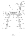
- Fig. 1 is a side elevational view of a foldable bath seat according to one embodiment of the present invention, showing the foldable bath seat in both a fully extended position for use and a fully folded position for storage and carrying;
- Fig. 2 is a front elevational view of the foldable bath seat of Fig. 1 , showing a top seat portion of the seat member having a central area configured in a concave profile;
- Fig. 3 is a top plane view of the foldable bath seat of Fig. 1 , showing the top seat portion of the seat member;
- Fig. 4 is a bottom plane view of the foldable bath seat of Fig. 1 , with leg extensions removed, showing the pivotal attachment of the leg assemblies to the seat member;
- Fig. 5 is a longitudinal cross-sectional view of the seat member of the foldable bath seat of Fig. 1 , showing bearing seats integrated with the bottom seat portion, for receiving U-shaped components of the respective leg assemblies;
- Fig. 6 is a partial longitudinally cross-sectional view of the seat member of Fig. 5 , showing the bearing seat in an enlarged scale for receiving a U-shaped component of a rear leg assembly;
- Fig. 7 is a side elevational view of a bearing bracket for use in combination with the bearing seats shown in Figs. 5 and 6 to pivotally connect the leg assemblies to the seat member;
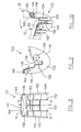
- Fig. 8 is a front elevational view of a backrest support used for pivotally connecting the backrest to the seat member of the foldable bath seat of Fig. 1 ;
- Fig. 9 is a cross-sectional view of the backrest support of Fig. 8 , taken along line 9-9;
- Fig. 10 is a cross-sectional view of the backrest support of Fig. 8 , taken along line 10-10, showing the reinforcing ribs thereof;
- Fig. 11 is a partial longitudinally cross-sectional view of the foldable bath seat of Fig. 2 , taken along line 11-11, showing the locking mechanism for locking the backrest in the upwardly extended position;
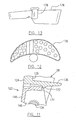
- Fig. 12 is a top plane view of a soap dish for selective attachment to the foldable bath seat of Fig. 1 ;
- Fig. 13 is a side elevational view of the soap dish of Fig. 12 ;
- Fig. 14 is a side elevational view of an arm rest for selective attachment to the foldable bath seat of Fig. 1 ;
- Fig. 15 is a cross-sectional view of a leg tip for attachment to a bottom end of the leg extension.
- Fig. 16 is a partial transversely cross-sectional view of the foldable bath seat of Fig. 4 , taken along line 16-16, showing a pair of hand grips concealed beneath the top seat portion and incorporated with the bottom seat portion of the seat member.
- a foldable bath seat according to one embodiment of the present invention, generally indicated by numeral 20, includes a seat member 22, a front leg assembly 24 and a rear leg assembly 26.
- a backrest 28 is also provided.
- the seat member 22 integrally has a top seat portion 30 and a bottom seat portion 32, both extending longitudinally between a front 34 and a rear 36 and extending transversely between opposed sides 38, 40 of the seat member 22.
- a longitudinal axis of the foldable bath seat 20 is indicated by numeral 42 and a transverse axis of the foldable bath seat 20 is indicated by numeral 44 (see Figs. 3-4 ).
- the seat member 22 is optionally configured with at least a central area 46 of the top seat portion 30, having a convex profile in a longitudinal side view (see Fig. 1 ) and having a concave profile in a front elevational view (see Fig. 2 ), in order to provide a comfortable seating for a user.
- the seat member 22 generally has a curved periphery along which a skirt 48 extending downwardly from the top seat portion 30, may be provided to increase the rigidity and strength of the seat member 22, as well as the aesthetic presentation.
- a plurality of ribs 50 may also be provided within the skirt 48, integrated with and formed as a part of the bottom seat portion 32.
- a plurality of draining holes 52 are optionally defined in the seat member 22, extending through the top seat portion 30'and the bottom seat portion 32.
- the edges of the draining holes 52 at the top seat portion 30 may be beveled and the draining holes 52 may also be reinforced by circular ribs 54 therearound which are integrated to the bottom seat portion 32 (see Fig. 4 ).
- bearing seats which may be integrated with the bottom seat portion 32 of the seat member 22, for pivotally receiving the respective front and rear leg assemblies 24, 26.
- four bearing seats 56 are provided, two located at the front 34 and two located at the rear 36 of the seat member 22, as shown in Figs. 4 and 5 .
- the bearing seats 56 and other features of the seat member 22 will be further described below.
- the front leg assembly 24 and the rear leg assembly 26 are substantially in a similar configuration except that the rear leg assembly 26 has a relatively smaller dimension in the transverse direction of the foldable bath seat 20. Therefore, as an example of those leg assemblies and for simplicity of description, only the front leg assembly 24 will be described in detail. It should be noted that the same reference numerals are used to indicate similar components in both front and rear assemblies 24, 26.
- the front leg assembly 24 includes two legs 58 connected by a transverse crossbar 60 (see Fig. 4 ), to form a U-shaped leg component (not indicated).
- the legs 58 and the crossbar 60 may be made of an integral tube.
- the transverse crossbar 60 is pivotally received in the respective two bearing seats 56 located at the front 34 of the seat member 22 and is secured in position by a pair of bearing brackets 62 which are removably attached to the respective bearing seats 56, to thereby form respective bearing supports to the U-shaped leg component. Therefore, the front leg assembly 24 is enabled to pivot about a transverse pivoting axis 64 (see Figs.
- each of the leg assemblies 24, 26 extend slightly outwardly from the connected transverse crossbar 60, such that each of the U-shaped leg components is slightly wider between opposed free ends than the length of the crossbar 60 (see Fig. 4 ), in order to provide a more stable support to the foldable bath seat 20 (see Fig. 2 ).
- each of the leg assemblies 24, 26 are slightly pivoted over a vertical position such that the respective front and rear legs 58 with the extensions 66 are in an inclined orientation to provide an elongated support area to the foldable bath seat 20 (see Fig. 1 ).
- Each of the legs 58 may be provided with a slidable leg extension 66.
- the slidable leg extension 66 is optionally made of a section of a tube in a telescoping connection with the leg 58.
- the leg extension 66 may have a plurality of positioning holes 68 (see Fig. 2 ) for selectively receiving a spring-biased pin/button (not shown) mounted to the leg 58 such that the leg extension 66 can be conveniently locked in a selected position with respect to the leg 58, for height adjustment of the foldable bath seat 20.
- Each of the leg extensions 60 may include a leg end tip 70 to prevent slippage of the foldable bath seat 20 when supported on a wet bottom surface of a bath tub, shower, or the like (not shown).
- the leg end tips shown in broken lines in Fig. 1 illustrate an adjusted position of the leg extension 66 such that the front and rear leg assemblies 24, 26 are in a shortest length.
- the leg end tip 70 is optionally made of a soft material such as rubber or other elastomer materials.
- the leg end tip 70 has a substantially cylindrical upper portion 72 and an enlarged lower portion 74 shaped like a shoe.
- the cylindrical upper portion 72 defines a central axis 76 slightly off from a position perpendicular to a bottom end 78 of the shoe-shaped lower portion 74, in order to correspond with the inclined orientation of the leg assemblies 24, 26 when in the fully extended position (see Fig. 1 ).
- the leg end tip 70 further defines a cylindrical hole 80 in the cylindrical upper portion 72 for receiving a bottom end of the leg extension 66.
- a recess 82 is defined at the bottom end 78 of the shoe-shaped lower portion 74.
- a water draining hole 84 extends through the leg end tip 70 from the hole 80 to the recess 82 such that water collected within the front and rear leg assemblies 24, 26 can be discharged.
- the bearing seats 56 which are substantially similar, are illustrated in different views.
- the bearing seat 56 near the front 34 of the seat member 22 is shown in a cross-sectional view cutting through a central plane thereof about which the bearing seat 56 is symmetric.
- the bearing seat 56 near the rear 36 of the seat member 22 is located closer to the longitudinal axis 42 (see Fig. 4 ) than the bearing seat 56 near the front 34, and thus a side other than a cross-section of the bearing seat 56 near the rear 36 is viewed in the cross-sectional view of the seat member 22 in Fig. 5 .
- Each of the bearing seats 56 includes two parallel side walls 86 having a transverse orientation and extending downwardly from a body of the seat member 22 and defining a semicircular bearing surface 88 therebetween.
- the two side walls 86 are spaced apart from respective screw bosses 90 which in turn are integrated with a reinforcing rib 50.
- the space between each side wall 86 and each screw boss 90 is indicated by numeral 92. Openings 94 are defined in the respective side walls 86.
- the bearing seat 56 is configured and positioned such that the center of the semicircular bearing surface 88 which forms the pivoting axis 64 (see Fig. 2 ), extends through the bearing seat member 22, thereby resulting in a relatively compact configuration of the foldable bath seat 20 when in a fully folded condition.
- the bearing seat 56 is optionally integrated with the bottom seat portion 32 as illustrated in this embodiment.
- the bearing bracket 62 When the crossbar 60 is placed within the bearing seat 56 as shown in Fig. 4 , the bearing bracket 62 is removably attached to each bearing seat 56 to thereby form a complete bearing support in order to pivotally connect the crossbar 60 to the seat member 22 as illustrated in Fig. 4 .
- the bearing bracket 62 has a body 96 defining a complimentary semicircular bearing surface 98, and two parallel insertion plates 100 extending from the body 96 of the bearing bracket 62.
- a groove 102 is provided between each insertion plate 100 and the body 96 of the bearing bracket 62.
- Two side extensions 104 extend laterally outside of the body 96 of the bearing bracket 62.
- a lock tongue 106 projects inwardly from a free end of each insertion plate 100.
- the bearing bracket 62 When the bearing bracket 62 is attached to a bearing seat 56, the two insertion plates 100 are inserted into the respective spaces 92 outside of the side walls 86 of the bearing seat 56 while the side walls 86 are received in the respective grooves 102 of the bearing bracket 62.
- the bearing bracket 62 When the bearing bracket 62 is placed in a position such that the semicircular bearing surface 88 of the bearing seat 56 and the semicircular bearing surface 98 of the bearing bracket 62 in combination form a complete bearing track, the lock tongue 106 of each insertion plate 100 engages the opening 94 in the side walls 86 of the bearing seat 56. Therefore, the bearing bracket 62 is removably secured in position.
- a side guide plate 110 is provided to restrain the transverse position of the leg 58 in the pivoting motion.
- the guide plates 110 may be optionally integrated with the reinforcing ribs 50 as illustrated in Fig. 4 according to this embodiment.
- a stopper 112 is further provided at each of the side guide plates 110 to position each of the legs 58 in the fully extended position as shown in Fig. 1 and to prevent the leg 58 from over-pivoting.
- the stopper 112 may be optionally integrated with the skirt 48 of the seat member 22 and may extend from the skirt 48 further downwardly to a level of the side guide plate 110.
- a recess 114 see Fig.
- a locking mechanism for example, a spring-biased pin/button (not shown), mounted on each leg 58 such that the spring-biased pin/button is pressed by the side guide plate 110 into the leg 58 unless the leg is pivoted to the fully extended position as shown in Fig. 1 , in which position the spring-biased pin/button projects and is received by the recess 114.
- a locking mechanism for example, a spring-biased pin/button (not shown) mounted on each leg 58 such that the spring-biased pin/button is pressed by the side guide plate 110 into the leg 58 unless the leg is pivoted to the fully extended position as shown in Fig. 1 , in which position the spring-biased pin/button projects and is received by the recess 114.
- two hand grips 116 are provided at opposed sides 38, 40 of the seat member 22 to allow a user to grip same for safely entering and exiting a bath tub.
- the hand grips 116 are optionally located beneath the top seat portion 30 and are integrated with the bottom seat portion 32, to thereby form a "concealed" hand grip in this embodiment.
- the concealed hand grips will not cause any inconvenience to and/or interference with the user's entering and exiting actions.
- a plurality of parallel ribs 118 having a smoothly curved profile are provided between a section of the skirt 48 and a supporting rim 120 which has a curvature similar to the section of the skirt 48 (see Fig. 4 ). Therefore, the combination of the skirt 48, the supporting rim 120 and the parallel extending ribs 118, forms the hand grip 116 to allow a very comfortable and secure grip by the user.
- the backrest 28 may be pivotally mounted to the rear 36 of the seat member 22, with an optional backrest support 122 between an upwardly extended position and a fully folded position (as shown in broken lines in Fig. 1 ) for storage and carrying.
- the backrest 28 includes a front portion 124 and a rear portion 126 defined, for example, within a substantially balloon-profiled periphery.
- the backrest 28 includes a skirt 128 along the balloon-profiled periphery, extending rearwardly from the front portion 124 to enhance the rigidity and strength of the backrest 28.
- a plurality of ribs 130 are provided within the peripheral skirt 128, and are integrated with the rear portion 126 (see Fig. 4 ).
- the ribs 130 form part of the rear portion 126 of the backrest 28.
- a U-shaped recess 132 (see Fig. 2 ) is defined in the backrest 28, extending upwardly and inwardly from a bottom portion of the balloon-profiled periphery, for receiving the backrest support 122.
- a pivoting pin 134 (see Fig. 1 ) which is received in a pair of aligned holes (not indicated) defined in the rear portion 126 of the backrest 28, extends across the U-shaped recess 132 to provide a pivotal connection between the backrest 28 and the backrest support 122 which is in turn, removably mounted to the rear 36 of the seat member 22.
- An elastically deformable lock mechanism 136 is provided at a top of the outwardly and inwardly extending U-shaped recess 132.
- An opening 138 may be optionally defined through the backrest 28 at a top peripheral area thereof, thereby forming a hand grip 140 (see Figs. 2 and 3 ) between the opening 138 and a top portion of the skirt 128, for convenience of folding and carrying the foldable bath seat 20.
- a plurality of ribs 142 may also be provided in the rear portion 126 of the back rest 28 between the top section of the skirt 128 and the opening 138.
- the backrest support 122 generally has a hook-like side profile including a base portion 144 attached to the bottom seat portion 32 of the seat member 22, and a rear portion 146 integrated with the base portion 144 and extending upwardly at the rear 36 of the seat member 22.
- the backrest support 122 including the integral base and rear portions 144, 146 may be made in a hollow configuration having a profiled top body 148 and outer and inner side plates 150, 152 with reinforcing ribs 154 extending between the respective outer and inner side plates 150, 152.
- a transverse groove 156 is defined by the profiled top body 148, for receiving a rear section of the skirt of the seat member 22 (shown in broken lines in Fig. 10 ) while the profiled top body 148 at the base portion 144 may abut an undersurface of the bottom seat portion of the seat member 22.
- Mounting screws (not shown) may be provided to fasten the backrest support 122 to the seat member 22.
- Numeral 158 indicates a selected location, for example, to mount the screws.
- Aligned holes 160 may be defined in the respective outer and inner side plates 150, 152 for receiving the transverse crossbar 60 of the rear leg assembly extended therethrough.
- the crossbar 60 is separated into left-hand and right-hand halves which are inserted oppositely inwardly from the respective outer side plates 150 into the holes 160 and are then connected together to form the U-shaped leg component.
- the U-shaped leg component including the transverse crossbar 60 with the rear legs 58 is so attached to the backrest support 122, the combination is then attached to the seat member 22 with the respective backrest support 122 and the crossbar 60 in position.
- the U-shaped component of the rear leg assembly need not be separated into two pieces and the one-piece U-shaped leg component may be placed in position after the backrest support 122 is attached to the seat member 22.
- a center groove 162 may be provided in the profiled top body 148 of the base portion 144 to allow a reinforcing rib 50 of the seat member 22 to extend therethrough.
- Holes 164 are defined in the respective outer and inner side plates 150, 152 at the rear portion 146 of the backrest support 122.
- the pivoting pin 134 is pivotally extended therethrough when the backrest 28 is attached to the backrest support 122 and the top of the rear portion 146 of the backrest support 122 is received within the U-shaped recess 132 of the backrest 28.
- Two stop shoulders 166 are provided at opposite sides of the top of the rear portion 146, to abut a ridge 168 of the backrest 28 defined in the U-shaped recess 132 (shown in broken lines in Fig. 10 ), in order to prevent the backrest 28 from over-pivoting when the backrest 28 reaches the upwardly extended position.
- a space 170 (see Fig. 8 ) between the two shoulders 166 allows the plastically deformable lock mechanism 136 to pass therethrough when the backrest 28 is pivoted towards the upwardly extended position.
- the elastically deformable lock mechanism 136 has a projecting member 172 (see Fig. 11 ) which abuts a rear end 174 of the top of the profiled top body 148 of the rear portion 146 of the backrest support 122, in order to lock the backrest 28 in the upwardly extended position.
- the resiliency of the elastically deformable lock mechanism 136 allows the elastically deformable lock mechanism 136 to disengage the projecting member 172 from the rear end 174 of the profiled top body 148 when being pulled upwardly to allow the backrest 28 to be pivoted towards the fully folded position.
- a pair of soap dishes 176 may be provided for selective attachment to the seat member 22.
- the soap dishes 176 illustrated in Figs. 12, 13 are an example only and may be configured in different shapes or styles.
- the soap dish 176 may optionally have a substantially cylindrical or slightly tapered conical attaching member 178 with an enlarged head to be removably inserted into and held in the respective recesses 180 defined in the respective sides 38, 40 of the seat member 22.
- the soap dish 176 may also include a plurality of water draining holes (not indicated) in the bottom thereof.
- a pair of armrests 182, for example, as illustrated in Fig. 14 may be optionally provided.
- Each of the armrests 182 has an attaching member 184 similar to the attaching member 178 of the soap dish in Fig. 13 , such that the armrest 182 may be received in the respective recesses 180 of the seat member 22, alternative to the soap dish 178.
- the recesses 180 of the seat member 22 may receive other accessories such as a shower nozzle head, etc.
- the seat member 22, backrest 28 and backrest support 122 may be made of any suitable materials, such as plastics, etc. When plastic material is used, these components may be made in a molding process.
- the legs 58 and leg extensions 66 may be made of any suitable materials such as metal materials, etc. When a metal material is selected, stainless steel tubes, aluminium tubes or other tubular materials may be chosen.
- the foldable bath seat according to the described embodiment of the present invention advantageously provides comfortable and secure seating for a user when bathing or showering in a bathtub and convenience and safety when entering and exiting the bathtub.
- the foldable bath seat according to the described embodiment of the invention also advantageously allows a very compact fully folded condition in which a height dimension H, as indicated in Fig. 1 , can be equal to or even smaller than 20 cm.
- the foldable bath seat according to the described embodiment of the present invention can be fully assembled and shipped in the folded condition. Therefore, it is convenient for user to use the foldable bath seat without any assembling procedure after unpacking this product.
Landscapes
- Health & Medical Sciences (AREA)
- Public Health (AREA)
- Epidemiology (AREA)
- General Health & Medical Sciences (AREA)
- Special Chairs (AREA)
- Vehicle Waterproofing, Decoration, And Sanitation Devices (AREA)
- Bathtubs, Showers, And Their Attachments (AREA)
Abstract
Description
- The present invention relates to a seat, and more particularly to a foldable bath seat which can be folded into a compact state for storage or carrying.
- Bath seats are generally used for assisting people in taking a bath or shower. However, the conventional bath seats were developed with specific applications in mind and it is usually necessary to select a different bath seat design for each application where the bath seat is needed. For example, bath seats may be used in the nursing field to allow a caregiver to put a patient who is unable to move by himself/herself on a bath seat and give the patient a bath. Bath seats may also be used to permit safely sitting in a bath tub while showering or bathing themselves by those with stability/balance challenges, those at risk of falling such as the elderly, post-surgery patients, people with injuries to the lower body region or pregnant women, etc. Those who require the use of a bath seat, usually have to try to find one that addresses their specific disability.
- A conventional - bath seat is generally large and usually has to be stored somewhere other than in the bathroom. Even those with conventional adjustable legs and/or foldable or collapsible configurations, still have a relatively large dimension, particularly the height dimension, even when in a retracted or folded condition for storage.
- Therefore, there is a need for a generally comfortable and stable bath seat for use in many application conditions, which allows for a relatively compact dimension when in a folded condition for storage and carrying.
- In accordance with one aspect of the present invention, there is a foldable bath seat which comprises a seat member integrally having a top seat portion and a bottom seat portion, extending longitudinally between a front and a rear and extending transversely between opposed sides of the seat member; and first and second leg assemblies pivotally mounted to the seat member at the respective front and rear of the seat member, each leg assembly including two legs connected by a transverse crossbar to form a U-shaped component, the transverse crossbar being pivotally mounted to the bottom seat portion of the seat member in order to allow the legs to pivot about a transverse pivoting axis extending through the seat member, between a folded position and an downwardly extended position
- In accordance with another aspect of the present invention, there is a foldable bath seat which comprises a seat member integrally having a top seat portion and a bottom seat portion, extending longitudinally between a front and a rear and extending transversely between opposed sides of the seat member; first and second leg assemblies pivotally mounted to the seat member at the respective front and rear of the seat member, each leg assembly including two legs pivotable about a transverse pivoting axis between a folded position and an downwardly extended position; and a backrest having a front portion and a rear portion, the backrest being pivotally mounted to the rear of the seat member to pivot between an upwardly extended position and a folded position.
- Further features and advantages of the present invention will become apparent from the following detailed description, taken in combination with the appended drawings, in which:
-
Fig. 1 is a side elevational view of a foldable bath seat according to one embodiment of the present invention, showing the foldable bath seat in both a fully extended position for use and a fully folded position for storage and carrying; -
Fig. 2 is a front elevational view of the foldable bath seat ofFig. 1 , showing a top seat portion of the seat member having a central area configured in a concave profile; -
Fig. 3 is a top plane view of the foldable bath seat ofFig. 1 , showing the top seat portion of the seat member; -
Fig. 4 is a bottom plane view of the foldable bath seat ofFig. 1 , with leg extensions removed, showing the pivotal attachment of the leg assemblies to the seat member; -
Fig. 5 is a longitudinal cross-sectional view of the seat member of the foldable bath seat ofFig. 1 , showing bearing seats integrated with the bottom seat portion, for receiving U-shaped components of the respective leg assemblies; -
Fig. 6 is a partial longitudinally cross-sectional view of the seat member ofFig. 5 , showing the bearing seat in an enlarged scale for receiving a U-shaped component of a rear leg assembly; -
Fig. 7 is a side elevational view of a bearing bracket for use in combination with the bearing seats shown inFigs. 5 and6 to pivotally connect the leg assemblies to the seat member; -
Fig. 8 is a front elevational view of a backrest support used for pivotally connecting the backrest to the seat member of the foldable bath seat ofFig. 1 ; -
Fig. 9 is a cross-sectional view of the backrest support ofFig. 8 , taken along line 9-9; -
Fig. 10 is a cross-sectional view of the backrest support ofFig. 8 , taken along line 10-10, showing the reinforcing ribs thereof; -
Fig. 11 is a partial longitudinally cross-sectional view of the foldable bath seat ofFig. 2 , taken along line 11-11, showing the locking mechanism for locking the backrest in the upwardly extended position; -
Fig. 12 is a top plane view of a soap dish for selective attachment to the foldable bath seat ofFig. 1 ; -
Fig. 13 is a side elevational view of the soap dish ofFig. 12 ; -
Fig. 14 is a side elevational view of an arm rest for selective attachment to the foldable bath seat ofFig. 1 ; -
Fig. 15 is a cross-sectional view of a leg tip for attachment to a bottom end of the leg extension; and -
Fig. 16 is a partial transversely cross-sectional view of the foldable bath seat ofFig. 4 , taken along line 16-16, showing a pair of hand grips concealed beneath the top seat portion and incorporated with the bottom seat portion of the seat member. - Referring to
Figs. 1-4 , a foldable bath seat according to one embodiment of the present invention, generally indicated bynumeral 20, includes aseat member 22, afront leg assembly 24 and arear leg assembly 26. Optionally, abackrest 28 is also provided. - Further reference is made to
Figs. 1-5 . Theseat member 22 integrally has atop seat portion 30 and abottom seat portion 32, both extending longitudinally between afront 34 and a rear 36 and extending transversely betweenopposed sides seat member 22. A longitudinal axis of thefoldable bath seat 20 is indicated bynumeral 42 and a transverse axis of thefoldable bath seat 20 is indicated by numeral 44 (seeFigs. 3-4 ). - The
seat member 22 is optionally configured with at least acentral area 46 of thetop seat portion 30, having a convex profile in a longitudinal side view (seeFig. 1 ) and having a concave profile in a front elevational view (seeFig. 2 ), in order to provide a comfortable seating for a user. Theseat member 22 generally has a curved periphery along which askirt 48 extending downwardly from thetop seat portion 30, may be provided to increase the rigidity and strength of theseat member 22, as well as the aesthetic presentation. A plurality of ribs 50 (seeFigs. 4 and5 ) may also be provided within theskirt 48, integrated with and formed as a part of thebottom seat portion 32. A plurality of drainingholes 52 are optionally defined in theseat member 22, extending through the top seat portion 30'and thebottom seat portion 32. The edges of the drainingholes 52 at thetop seat portion 30 may be beveled and the drainingholes 52 may also be reinforced by circular ribs 54 therearound which are integrated to the bottom seat portion 32 (seeFig. 4 ). - Further provided are a plurality of bearing seats which may be integrated with the
bottom seat portion 32 of theseat member 22, for pivotally receiving the respective front andrear leg assemblies seats 56 are provided, two located at thefront 34 and two located at the rear 36 of theseat member 22, as shown inFigs. 4 and5 . Thebearing seats 56 and other features of theseat member 22 will be further described below. - The
front leg assembly 24 and therear leg assembly 26 are substantially in a similar configuration except that therear leg assembly 26 has a relatively smaller dimension in the transverse direction of thefoldable bath seat 20. Therefore, as an example of those leg assemblies and for simplicity of description, only thefront leg assembly 24 will be described in detail. It should be noted that the same reference numerals are used to indicate similar components in both front andrear assemblies - The
front leg assembly 24 includes twolegs 58 connected by a transverse crossbar 60 (seeFig. 4 ), to form a U-shaped leg component (not indicated). Thelegs 58 and thecrossbar 60 may be made of an integral tube. Thetransverse crossbar 60 is pivotally received in the respective two bearingseats 56 located at thefront 34 of theseat member 22 and is secured in position by a pair ofbearing brackets 62 which are removably attached to the respective bearingseats 56, to thereby form respective bearing supports to the U-shaped leg component. Therefore, thefront leg assembly 24 is enabled to pivot about a transverse pivoting axis 64 (seeFigs. 2 and4 ) extending through thebottom seat portion 32 of theseat member 22, between a folded position (as illustrated by the leg assemblies shown in broken lines inFig. 1 ) and a downwardly extended position. Thelegs 58 of each of the leg assemblies 24, 26 extend slightly outwardly from the connectedtransverse crossbar 60, such that each of the U-shaped leg components is slightly wider between opposed free ends than the length of the crossbar 60 (seeFig. 4 ), in order to provide a more stable support to the foldable bath seat 20 (seeFig. 2 ). In the fully downwardly extended position, each of the leg assemblies 24, 26 are slightly pivoted over a vertical position such that the respective front andrear legs 58 with theextensions 66 are in an inclined orientation to provide an elongated support area to the foldable bath seat 20 (seeFig. 1 ). - Each of the
legs 58 may be provided with aslidable leg extension 66. In this embodiment, theslidable leg extension 66 is optionally made of a section of a tube in a telescoping connection with theleg 58. Theleg extension 66 may have a plurality of positioning holes 68 (seeFig. 2 ) for selectively receiving a spring-biased pin/button (not shown) mounted to theleg 58 such that theleg extension 66 can be conveniently locked in a selected position with respect to theleg 58, for height adjustment of thefoldable bath seat 20. Each of theleg extensions 60 may include aleg end tip 70 to prevent slippage of thefoldable bath seat 20 when supported on a wet bottom surface of a bath tub, shower, or the like (not shown). The leg end tips shown in broken lines inFig. 1 , illustrate an adjusted position of theleg extension 66 such that the front and rear leg assemblies 24, 26 are in a shortest length. - As illustrated in
Fig. 15 , theleg end tip 70 is optionally made of a soft material such as rubber or other elastomer materials. Theleg end tip 70 has a substantially cylindricalupper portion 72 and an enlargedlower portion 74 shaped like a shoe. The cylindricalupper portion 72 defines acentral axis 76 slightly off from a position perpendicular to abottom end 78 of the shoe-shapedlower portion 74, in order to correspond with the inclined orientation of theleg assemblies Fig. 1 ). Theleg end tip 70 further defines acylindrical hole 80 in the cylindricalupper portion 72 for receiving a bottom end of theleg extension 66. Arecess 82 is defined at thebottom end 78 of the shoe-shapedlower portion 74. Awater draining hole 84 extends through theleg end tip 70 from thehole 80 to therecess 82 such that water collected within the front andrear leg assemblies - With reference to
Figs. 4-7 , the bearingseats 56 which are substantially similar, are illustrated in different views. InFig. 5 , the bearingseat 56 near thefront 34 of theseat member 22 is shown in a cross-sectional view cutting through a central plane thereof about which the bearingseat 56 is symmetric. The bearingseat 56 near the rear 36 of theseat member 22 is located closer to the longitudinal axis 42 (seeFig. 4 ) than the bearingseat 56 near the front 34, and thus a side other than a cross-section of the bearingseat 56 near the rear 36 is viewed in the cross-sectional view of theseat member 22 inFig. 5 . Bearingseat 56 inFig. 6 is shown in a upside-down cross-sectional view which is cut through a plane slightly off a central symmetrical plane of the bearingseat 56, presenting differently from the central cross-sectional view of the bearingseat 56 near thefront 34 of theseat member 22 inFig. 5 . Each of the bearing seats 56 includes twoparallel side walls 86 having a transverse orientation and extending downwardly from a body of theseat member 22 and defining asemicircular bearing surface 88 therebetween. The twoside walls 86 are spaced apart fromrespective screw bosses 90 which in turn are integrated with a reinforcingrib 50. The space between eachside wall 86 and eachscrew boss 90 is indicated bynumeral 92.Openings 94 are defined in therespective side walls 86. It should be noted that the bearingseat 56 is configured and positioned such that the center of thesemicircular bearing surface 88 which forms the pivoting axis 64 (seeFig. 2 ), extends through the bearingseat member 22, thereby resulting in a relatively compact configuration of thefoldable bath seat 20 when in a fully folded condition. The bearingseat 56 is optionally integrated with thebottom seat portion 32 as illustrated in this embodiment. - When the
crossbar 60 is placed within the bearingseat 56 as shown inFig. 4 , the bearingbracket 62 is removably attached to each bearingseat 56 to thereby form a complete bearing support in order to pivotally connect thecrossbar 60 to theseat member 22 as illustrated inFig. 4 . The bearingbracket 62 has abody 96 defining a complimentarysemicircular bearing surface 98, and twoparallel insertion plates 100 extending from thebody 96 of the bearingbracket 62. Agroove 102 is provided between eachinsertion plate 100 and thebody 96 of the bearingbracket 62. Twoside extensions 104 extend laterally outside of thebody 96 of the bearingbracket 62. Alock tongue 106 projects inwardly from a free end of eachinsertion plate 100. When the bearingbracket 62 is attached to a bearingseat 56, the twoinsertion plates 100 are inserted into therespective spaces 92 outside of theside walls 86 of the bearingseat 56 while theside walls 86 are received in therespective grooves 102 of the bearingbracket 62. When the bearingbracket 62 is placed in a position such that thesemicircular bearing surface 88 of the bearingseat 56 and thesemicircular bearing surface 98 of the bearingbracket 62 in combination form a complete bearing track, thelock tongue 106 of eachinsertion plate 100 engages theopening 94 in theside walls 86 of the bearingseat 56. Therefore, the bearingbracket 62 is removably secured in position. Because of the resiliency and the flexibility of theinsertion plate 100 and the beveled front end of thelock tongue 106, it is relatively easy to elastically deform theinsertion plates 100 when plugged into the bearingbracket 62. The bearingbracket 96 can also be removed with a little effort. Mounting screws (not shown) may also be provided to secure thebearing bracket 62 to the bearingseat 56, extending through mounting holes (not shown) in theside extension 104 of the mountingbracket 62 to be engaged within threadedholes 108 in thescrew bosses 90 of the seat member 22 (seeFig. 5 ). - In
Figs. 4 and5 , aside guide plate 110 is provided to restrain the transverse position of theleg 58 in the pivoting motion. Theguide plates 110 may be optionally integrated with the reinforcingribs 50 as illustrated inFig. 4 according to this embodiment. Astopper 112 is further provided at each of theside guide plates 110 to position each of thelegs 58 in the fully extended position as shown inFig. 1 and to prevent theleg 58 from over-pivoting. Thestopper 112 may be optionally integrated with theskirt 48 of theseat member 22 and may extend from theskirt 48 further downwardly to a level of theside guide plate 110. A recess 114 (seeFig. 5 ) may be optionally defined in a location of theside guide plate 110 adjacent to thestopper 112, for selectively receiving a locking mechanism, for example, a spring-biased pin/button (not shown), mounted on eachleg 58 such that the spring-biased pin/button is pressed by theside guide plate 110 into theleg 58 unless the leg is pivoted to the fully extended position as shown inFig. 1 , in which position the spring-biased pin/button projects and is received by therecess 114. - With reference to
Figs. 4 and16 , twohand grips 116 are provided atopposed sides seat member 22 to allow a user to grip same for safely entering and exiting a bath tub. The hand grips 116 are optionally located beneath thetop seat portion 30 and are integrated with thebottom seat portion 32, to thereby form a "concealed" hand grip in this embodiment. The concealed hand grips will not cause any inconvenience to and/or interference with the user's entering and exiting actions. A plurality ofparallel ribs 118 having a smoothly curved profile are provided between a section of theskirt 48 and a supportingrim 120 which has a curvature similar to the section of the skirt 48 (seeFig. 4 ). Therefore, the combination of theskirt 48, the supportingrim 120 and the parallel extendingribs 118, forms thehand grip 116 to allow a very comfortable and secure grip by the user. - In
Figs. 1-4 , thebackrest 28 may be pivotally mounted to the rear 36 of theseat member 22, with anoptional backrest support 122 between an upwardly extended position and a fully folded position (as shown in broken lines inFig. 1 ) for storage and carrying. Thebackrest 28 includes afront portion 124 and arear portion 126 defined, for example, within a substantially balloon-profiled periphery. Similarly to theseat member 22, thebackrest 28 includes askirt 128 along the balloon-profiled periphery, extending rearwardly from thefront portion 124 to enhance the rigidity and strength of thebackrest 28. Optionally, a plurality ofribs 130 are provided within theperipheral skirt 128, and are integrated with the rear portion 126 (seeFig. 4 ). Theribs 130 form part of therear portion 126 of thebackrest 28. A U-shaped recess 132 (seeFig. 2 ) is defined in thebackrest 28, extending upwardly and inwardly from a bottom portion of the balloon-profiled periphery, for receiving thebackrest support 122. A pivoting pin 134 (seeFig. 1 ) which is received in a pair of aligned holes (not indicated) defined in therear portion 126 of thebackrest 28, extends across theU-shaped recess 132 to provide a pivotal connection between thebackrest 28 and thebackrest support 122 which is in turn, removably mounted to the rear 36 of theseat member 22. An elasticallydeformable lock mechanism 136 is provided at a top of the outwardly and inwardly extendingU-shaped recess 132. Anopening 138 may be optionally defined through thebackrest 28 at a top peripheral area thereof, thereby forming a hand grip 140 (seeFigs. 2 and3 ) between theopening 138 and a top portion of theskirt 128, for convenience of folding and carrying thefoldable bath seat 20. Similar to theribs 118 of the hand grips 116 shown inFig. 16 , a plurality of ribs 142 (seeFig. 4 ) may also be provided in therear portion 126 of theback rest 28 between the top section of theskirt 128 and theopening 138. - Referring to
Figs. 1-4 and8-11 , thebackrest support 122 generally has a hook-like side profile including abase portion 144 attached to thebottom seat portion 32 of theseat member 22, and arear portion 146 integrated with thebase portion 144 and extending upwardly at the rear 36 of theseat member 22. Thebackrest support 122 including the integral base andrear portions top body 148 and outer andinner side plates ribs 154 extending between the respective outer andinner side plates base portion 144, atransverse groove 156 is defined by the profiledtop body 148, for receiving a rear section of the skirt of the seat member 22 (shown in broken lines inFig. 10 ) while the profiledtop body 148 at thebase portion 144 may abut an undersurface of the bottom seat portion of theseat member 22. Mounting screws (not shown) may be provided to fasten thebackrest support 122 to theseat member 22.Numeral 158 indicates a selected location, for example, to mount the screws. Alignedholes 160 may be defined in the respective outer andinner side plates transverse crossbar 60 of the rear leg assembly extended therethrough. In order to assemble the rear leg assembly to theseat member 22, thecrossbar 60 is separated into left-hand and right-hand halves which are inserted oppositely inwardly from the respectiveouter side plates 150 into theholes 160 and are then connected together to form the U-shaped leg component. When the U-shaped leg component including thetransverse crossbar 60 with therear legs 58, is so attached to thebackrest support 122, the combination is then attached to theseat member 22 with therespective backrest support 122 and thecrossbar 60 in position. Alternatively, if theholes 160 in the respective outer andinner side plates backrest support 122 are replaced by open recesses, the U-shaped component of the rear leg assembly need not be separated into two pieces and the one-piece U-shaped leg component may be placed in position after thebackrest support 122 is attached to theseat member 22. Acenter groove 162 may be provided in the profiledtop body 148 of thebase portion 144 to allow a reinforcingrib 50 of theseat member 22 to extend therethrough. -
Holes 164 are defined in the respective outer andinner side plates rear portion 146 of thebackrest support 122. The pivotingpin 134 is pivotally extended therethrough when thebackrest 28 is attached to thebackrest support 122 and the top of therear portion 146 of thebackrest support 122 is received within theU-shaped recess 132 of thebackrest 28. Two stopshoulders 166 are provided at opposite sides of the top of therear portion 146, to abut aridge 168 of thebackrest 28 defined in the U-shaped recess 132 (shown in broken lines inFig. 10 ), in order to prevent thebackrest 28 from over-pivoting when thebackrest 28 reaches the upwardly extended position. - A space 170 (see
Fig. 8 ) between the twoshoulders 166 allows the plasticallydeformable lock mechanism 136 to pass therethrough when thebackrest 28 is pivoted towards the upwardly extended position. The elasticallydeformable lock mechanism 136 has a projecting member 172 (seeFig. 11 ) which abuts arear end 174 of the top of the profiledtop body 148 of therear portion 146 of thebackrest support 122, in order to lock thebackrest 28 in the upwardly extended position. The resiliency of the elasticallydeformable lock mechanism 136 allows the elasticallydeformable lock mechanism 136 to disengage the projectingmember 172 from therear end 174 of the profiledtop body 148 when being pulled upwardly to allow thebackrest 28 to be pivoted towards the fully folded position. - Referring to
Figs. 2-3 and12-13 , a pair ofsoap dishes 176 may be provided for selective attachment to theseat member 22. Thesoap dishes 176 illustrated inFigs. 12, 13 are an example only and may be configured in different shapes or styles. Thesoap dish 176 may optionally have a substantially cylindrical or slightly taperedconical attaching member 178 with an enlarged head to be removably inserted into and held in therespective recesses 180 defined in therespective sides seat member 22. Thesoap dish 176 may also include a plurality of water draining holes (not indicated) in the bottom thereof. - A pair of
armrests 182, for example, as illustrated inFig. 14 , may be optionally provided. Each of thearmrests 182 has an attachingmember 184 similar to the attachingmember 178 of the soap dish inFig. 13 , such that thearmrest 182 may be received in therespective recesses 180 of theseat member 22, alternative to thesoap dish 178. Furthermore, therecesses 180 of theseat member 22 may receive other accessories such as a shower nozzle head, etc. - The
seat member 22,backrest 28 andbackrest support 122 may be made of any suitable materials, such as plastics, etc. When plastic material is used, these components may be made in a molding process. Thelegs 58 andleg extensions 66 may be made of any suitable materials such as metal materials, etc. When a metal material is selected, stainless steel tubes, aluminium tubes or other tubular materials may be chosen. - The foldable bath seat according to the described embodiment of the present invention, advantageously provides comfortable and secure seating for a user when bathing or showering in a bathtub and convenience and safety when entering and exiting the bathtub. The foldable bath seat according to the described embodiment of the invention also advantageously allows a very compact fully folded condition in which a height dimension H, as indicated in
Fig. 1 , can be equal to or even smaller than 20 cm. The foldable bath seat according to the described embodiment of the present invention can be fully assembled and shipped in the folded condition. Therefore, it is convenient for user to use the foldable bath seat without any assembling procedure after unpacking this product. - The above description is meant to be exemplary only and one skilled in the art will recognize that changes may be made to the embodiment described without departing from the scope of the invention disclosed. Modifications which fall within the scope of the present invention will be apparent to those skilled in the art in light of a review of this disclosure, and such modifications are intended to fall within the appended claims.
Claims (19)
- A foldable bath seat comprising:a seat member integrally having a top seat portion and a bottom seat portion, extending longitudinally between a front and a rear and extending transversely between opposed sides of the seat member; andfirst and second leg assemblies pivotally mounted to the seat member at the respective front and rear of the seat member, each leg assembly including two legs connected by a transverse crossbar to form a U-shaped component, the transverse crossbar being pivotally mounted to the bottom seat portion of the seat member in order to allow the legs to pivot about a transverse pivoting axis extending through the seat member, between a folded position and an downwardly extended position.
- The foldable bath seat as defined in claim 1 wherein the bottom seat portion comprises at least one bearing seat for receiving each of the transverse crossbars pivotally positioned therein, and wherein each of the leg assemblies comprises at least one bearing bracket to be removably attached to the at least one bearing seat to thereby form a bearing support to each of the U-shaped components.
- The foldable bath seat as defined in claim 2 wherein each of the bearing brackets comprises an elastically deformable locking member for locking the bearing bracket together with the bearing seat.
- The foldable bath seat as defined in claim 1 wherein each of the legs comprises a slidable extension for height adjustment of the foldable bath seat.
- The foldable bath seat as defined in claim 1 wherein the seat member comprises a pair of hand grips concealed beneath the top seat portion and integrated with the bottom seat portion of the seat member.
- The foldable bath seat as defined in claim 1 wherein the seat member is configured with at least a central area of the top seat portion having a convex profile in a longitudinal side view of the bath seat and having a concave profile in a front elevational view of the bath seat.
- The foldable bath seat as defined in claim 1 further comprising:a backrest having a front portion and a rear portion; anda backrest support removably attached to the seat member and pivotally connected to the backrest to allow the backrest to pivot between a folded position and an upwardly extended position.
- The foldable bath seat as defined in claim 7 wherein the backrest support comprises a base portion attached to the bottom seat portion and a rear portion integrated with the base portion and extending upwardly at the rear of the seat member, the rear portion being pivotally connected with the backrest by a pivotal pin.
- The foldable bath seat as defined in claim 8 wherein the base portion of the backrest support defines at least one opening for receiving the transverse crossbar of one leg assembly mounted to the seat member at the rear, extending therethrough.
- The foldable bath seat as defined in claim 8 wherein the backrest comprises an elastically deformable lock mechanism for releaseably engaging the rear portion of the backrest support, thereby locking the backrest in the upwardly extended position.
- The foldable bath seat as defined in claim 7 wherein the backrest comprises an integrated hand grip.
- A foldable bath seat comprising:a seat member integrally having a top seat portion and a bottom seat portion, extending longitudinally between a front and a rear and extending transversely between opposed sides of the seat member;first and second leg assemblies pivotally mounted to the seat member at the respective front and rear of the seat member, each leg assembly including two legs pivotable about a transverse pivoting axis, between a folded position and an downwardly extended position; anda backrest having a front portion and a rear portion, the backrest being pivotally mounted to the rear of the seat member to pivot between an upwardly extended position and a folded position.
- The foldable bath seat as defined in claim 12 wherein the bottom seat portion is integrated with a plurality of reinforcing ribs.
- The foldable bath seat as defined in claim 13 wherein rear portion of the backrest is integrated with a plurality of reinforcing ribs.
- The foldable bath seat as defined in claim 13 wherein each of the legs of the respective leg assemblies comprises a slidable leg extension.
- The foldable bath seat as defined in claim 13 comprising a height dimension in a fully folded condition equal to or less than 20 cm.
- The foldable bath seat as defined in claim 13 wherein the seat member comprises a pair of hand grips at the respective opposed sides of the seat member concealed beneath the top seat portion and integrated with the bottom seat portion.
- The foldable bath seat as defined in claim 13 further comprising a soap dish selectively attached to the seat member.
- The foldable bath seat as defined in claim 13 further comprising a pair of armrests selectively attached to the seat member.
Applications Claiming Priority (1)
| Application Number | Priority Date | Filing Date | Title |
|---|---|---|---|
| US11/741,869 US7549702B2 (en) | 2007-04-30 | 2007-04-30 | Foldable bath seat |
Publications (2)
| Publication Number | Publication Date |
|---|---|
| EP1987752A1 true EP1987752A1 (en) | 2008-11-05 |
| EP1987752B1 EP1987752B1 (en) | 2010-03-31 |
Family
ID=38537698
Family Applications (1)
| Application Number | Title | Priority Date | Filing Date |
|---|---|---|---|
| EP07016359A Not-in-force EP1987752B1 (en) | 2007-04-30 | 2007-08-21 | Foldable bath seat |
Country Status (6)
| Country | Link |
|---|---|
| US (1) | US7549702B2 (en) |
| EP (1) | EP1987752B1 (en) |
| CN (1) | CN101297723B (en) |
| AT (1) | ATE462336T1 (en) |
| CA (1) | CA2594142C (en) |
| DE (1) | DE602007005614D1 (en) |
Cited By (6)
| Publication number | Priority date | Publication date | Assignee | Title |
|---|---|---|---|---|
| WO2010144422A3 (en) * | 2009-06-08 | 2011-02-24 | George Allen Mccabe | A perineal self-cleansing system and method of use |
| EP2338397A1 (en) * | 2009-12-22 | 2011-06-29 | Invacare International Sàrl | Shower chair |
| EP2486834A1 (en) * | 2011-02-02 | 2012-08-15 | Invacare International Sàrl | Shower chair |
| EP2557977A4 (en) * | 2011-03-17 | 2014-05-28 | Evolution Technologies Inc | Bath chair |
| GB2525861A (en) * | 2014-05-05 | 2015-11-11 | David Chung | A seating device |
| US9763545B2 (en) | 2011-03-17 | 2017-09-19 | Evolution Technologies Inc. | Bath chair |
Families Citing this family (34)
| Publication number | Priority date | Publication date | Assignee | Title |
|---|---|---|---|---|
| US8166584B2 (en) | 2000-06-13 | 2012-05-01 | Wcm Industries, Inc. | Overflow assembly for bathtubs and the like |
| US9045886B2 (en) | 2000-06-13 | 2015-06-02 | WCW Industries, Inc. | Device for concealing a plate associated with overflow plumbing |
| US8769736B2 (en) * | 2010-10-01 | 2014-07-08 | Wcm Industries, Inc. | Device for concealing a plate associated with overflow plumbing |
| GB2446575B (en) * | 2007-02-17 | 2011-04-13 | Dlp Ltd | Improvements in or relating to padded shower seats |
| US8262160B2 (en) * | 2008-11-14 | 2012-09-11 | Mehri Mafi | Adjustable padded chair |
| US20100295350A1 (en) * | 2008-12-18 | 2010-11-25 | Daniel Seth Barman | Ergonomic musician's stool |
| CN102028366B (en) * | 2009-09-30 | 2012-11-07 | 明门香港股份有限公司 | child seat |
| US8636319B1 (en) * | 2009-10-13 | 2014-01-28 | Don Parker, Jr. | Cup holder support apparatus |
| US8182031B1 (en) * | 2010-01-27 | 2012-05-22 | Mackenzie Eric K | Poker kit with chairs and table |
| US20110198902A1 (en) * | 2010-02-15 | 2011-08-18 | Phillip Renbarger | Collapsible massage stool systems |
| USD645679S1 (en) | 2010-07-29 | 2011-09-27 | Moen Incorporated | Seat |
| USD645680S1 (en) | 2010-07-29 | 2011-09-27 | Moen Incorporated | Seat |
| US8474916B2 (en) * | 2011-01-14 | 2013-07-02 | Smithworks, Inc. | Selectively configurable chair system |
| CN202269691U (en) | 2011-04-25 | 2012-06-13 | 克斯克管理公司 | Foldable seat |
| US8979184B2 (en) * | 2011-08-23 | 2015-03-17 | Todd W. Stafford | Swivel camp chair |
| DE102016106236B4 (en) * | 2015-04-16 | 2025-03-20 | Sico Incorporated | TABLE AND SEATING DEVICE |
| US9756935B2 (en) * | 2015-05-24 | 2017-09-12 | David Demichael | Convertible, integral, dining table, coffee table, serving table, desk, bed, bench and beach lounger utilizing a unique hinging system |
| US10563385B1 (en) | 2016-05-17 | 2020-02-18 | Wcm Industries, Inc. | Overflow cover interconnection system |
| US10595684B2 (en) | 2016-07-07 | 2020-03-24 | Marjory McCaffery | Bathing apparatuses and methods of making and using the same |
| US10443220B2 (en) | 2016-08-12 | 2019-10-15 | Wcm Industries, Inc. | Device for providing improved drainage |
| CN107826001B (en) * | 2016-09-16 | 2020-05-22 | 明门瑞士股份有限公司 | Supporting leg and child safety seat assembly thereof |
| CN106923548A (en) * | 2017-02-27 | 2017-07-07 | 上海理工大学 | A kind of Portable stool |
| US10722046B1 (en) * | 2017-05-11 | 2020-07-28 | Foundations Worldwide, Inc. | Adjustable height child seat |
| US11089909B2 (en) | 2018-04-23 | 2021-08-17 | Bryce Dickinson | Bidet for use in tub or shower |
| US11795676B2 (en) | 2018-04-23 | 2023-10-24 | Bryce A Dickinson | Bidet and dispenser for use in tub or shower |
| US11019924B2 (en) * | 2019-02-13 | 2021-06-01 | Grady-White Boats, Inc. | Fishing rod storage system |
| CA3140720A1 (en) | 2019-06-04 | 2020-12-10 | Yeti Coolers, Llc | Portable chair |
| US10881211B1 (en) | 2020-01-29 | 2021-01-05 | Hamad M. A. H. Al-Salloom | Collapsible chair |
| USD1003406S1 (en) | 2020-03-13 | 2023-10-31 | Wcm Industries, Inc. | Cover for a bathtub overflow system |
| US11814832B2 (en) | 2020-03-13 | 2023-11-14 | Wcm Industries, Inc. | Overflow covers and overflow systems for bathtubs |
| CN114073380B (en) * | 2020-08-17 | 2024-10-18 | Cvs药局有限公司 | Shower Chairs and Shower Chair Kits |
| US11324339B1 (en) * | 2020-10-28 | 2022-05-10 | Frank Ciaramitaro | Photographing seat assembly |
| US11950735B1 (en) | 2021-03-15 | 2024-04-09 | Faith A. Griffin | Shaving assistance platform |
| CN115299800A (en) * | 2022-09-05 | 2022-11-08 | 同济人工智能研究院(苏州)有限公司 | Multifunctional bath chair |
Citations (4)
| Publication number | Priority date | Publication date | Assignee | Title |
|---|---|---|---|---|
| US5845962A (en) * | 1997-03-24 | 1998-12-08 | Forever Young Enterprise Co., Ltd. | Foldable chair |
| WO1999007256A2 (en) | 1997-08-05 | 1999-02-18 | Tubular Fabricators Industry, Inc. | Foldable seating device |
| US20030102700A1 (en) * | 2001-12-04 | 2003-06-05 | Fang-Sheng Lin | Combination type bath chair |
| US7121620B1 (en) * | 2005-08-12 | 2006-10-17 | Hui Zhou Andon Industries Co., Ltd. | Foldable bath bench |
Family Cites Families (42)
| Publication number | Priority date | Publication date | Assignee | Title |
|---|---|---|---|---|
| US1922418A (en) * | 1930-09-09 | 1933-08-15 | Ko Rect Posture Chair Company | Posture regulating chair |
| US2849054A (en) * | 1956-10-29 | 1958-08-26 | J E Meacham | Folding furniture structure |
| US2966204A (en) * | 1958-06-26 | 1960-12-27 | Caravias Nicoletta | Folding chair |
| US2978012A (en) * | 1958-09-19 | 1961-04-04 | Dale G Norseen | Foldable utility chair |
| US3765718A (en) * | 1972-01-10 | 1973-10-16 | C Chen | Folding chair |
| US4253203A (en) * | 1979-09-04 | 1981-03-03 | Temco Products, Inc. | Folding transfer bench |
| US4359791A (en) * | 1979-09-04 | 1982-11-23 | Temco Products, Inc. | Folding transfer bench with improved roller and arm assembly |
| US4472844A (en) * | 1982-09-13 | 1984-09-25 | Mace Ronald L | Tub shower seat |
| US4520515A (en) * | 1983-03-21 | 1985-06-04 | Temco Home Health Care Products, Inc. | Three point clamping means for a shower bench |
| US4475256A (en) * | 1983-03-21 | 1984-10-09 | Temco Home Health Care Products, Inc. | Shower transfer bench |
| US5048132A (en) | 1990-01-30 | 1991-09-17 | Phyllis Rizzo | Bath/shower seat assembly and enclosure |
| USD347526S (en) * | 1991-08-12 | 1994-06-07 | Hamilton Robert H | Transfer bench |
| US5335377A (en) * | 1993-09-23 | 1994-08-09 | Masyada Frank G | Handicap bath chair |
| CN2181855Y (en) * | 1993-10-25 | 1994-11-09 | 中国有色金属工业总公司西北铝加工厂 | Portable Folding Travel Stool |
| US5388286A (en) | 1993-12-08 | 1995-02-14 | Davenport; Sharon G. | Infant bath seat device |
| US5806110A (en) | 1994-07-11 | 1998-09-15 | Kunz; Richard Don | Handicap bath assist device |
| US6105183A (en) * | 1995-10-06 | 2000-08-22 | Invacare Corporation | Reversible transfer bench |
| US5848822A (en) * | 1997-04-01 | 1998-12-15 | Wu; Tien Tzu | Folding collapsible chair |
| US5887297A (en) * | 1997-05-09 | 1999-03-30 | Sutor; Sebastian | Bath tub shower adjustable seat |
| US5822809A (en) * | 1997-08-29 | 1998-10-20 | Gallo; Thomas S. | Transfer seat apparatus |
| US6039403A (en) * | 1998-04-16 | 2000-03-21 | Hargroder; Todd | Shower/tub transfer chair |
| USD411054S (en) * | 1998-09-25 | 1999-06-15 | Russell G Williams | Bathing chair |
| US6056353A (en) * | 1998-11-16 | 2000-05-02 | Meara; Laura | Folding adjustable chair to accommodate joint dysfunction |
| US5937454A (en) * | 1998-11-18 | 1999-08-17 | Drew; Kathleen | Bathing chair |
| US6015185A (en) * | 1999-03-11 | 2000-01-18 | Meco Corporation | Gate-fold chair |
| US6122776A (en) * | 1999-09-03 | 2000-09-26 | Cheng; Yu Wen | Bathing chair |
| US6195813B1 (en) | 1999-10-01 | 2001-03-06 | Mario G. Orcini | Collapsible shower chair |
| US6182304B1 (en) * | 2000-02-11 | 2001-02-06 | Frans V. Freeberg | Bathing transfer apparatus |
| USD439429S1 (en) | 2000-05-03 | 2001-03-27 | Higgs Medical Products, Llc | Bath bench |
| US6702384B1 (en) * | 2001-10-12 | 2004-03-09 | Christopher D. Brown | Support device |
| US6676208B2 (en) * | 2002-05-29 | 2004-01-13 | Kun-Chung Lu | Combined chair and object support |
| US20040051365A1 (en) * | 2002-05-31 | 2004-03-18 | Rubbermaid Commercial Products Llc | Transfer bench |
| US6921135B2 (en) * | 2002-09-04 | 2005-07-26 | Craig Ellis | Child's adjustable chair |
| USD479068S1 (en) * | 2002-12-10 | 2003-09-02 | Moen Incorporated | Transfer bench seat back |
| US6698830B1 (en) * | 2002-12-31 | 2004-03-02 | Ronald K. Gaines | Portable seat and storage apparatus |
| US6969112B1 (en) * | 2003-01-29 | 2005-11-29 | Milton Sherrill | Collapsible chair assembly |
| USD519291S1 (en) * | 2003-10-08 | 2006-04-25 | Higgs Paul E | Bath chair |
| CN2667971Y (en) * | 2003-12-12 | 2005-01-05 | 际诺思(厦门)轻工制品有限公司 | Foldable chair |
| US6974191B2 (en) * | 2004-02-04 | 2005-12-13 | Medical Depot, Inc. | Shower chair with interlocking arms |
| US6957865B1 (en) * | 2004-04-14 | 2005-10-25 | Invacare Corporation | Adjustable chair |
| USD526517S1 (en) | 2004-04-26 | 2006-08-15 | Invacare Corporation | Chair |
| CN2776253Y (en) * | 2005-01-13 | 2006-05-03 | 佛山市南海建泰铝制品有限公司 | Spout type folding bath chair |
-
2007
- 2007-04-30 US US11/741,869 patent/US7549702B2/en active Active
- 2007-07-19 CA CA2594142A patent/CA2594142C/en active Active
- 2007-08-21 EP EP07016359A patent/EP1987752B1/en not_active Not-in-force
- 2007-08-21 DE DE602007005614T patent/DE602007005614D1/en active Active
- 2007-08-21 AT AT07016359T patent/ATE462336T1/en not_active IP Right Cessation
- 2007-08-24 CN CN2007101469168A patent/CN101297723B/en not_active Expired - Fee Related
Patent Citations (4)
| Publication number | Priority date | Publication date | Assignee | Title |
|---|---|---|---|---|
| US5845962A (en) * | 1997-03-24 | 1998-12-08 | Forever Young Enterprise Co., Ltd. | Foldable chair |
| WO1999007256A2 (en) | 1997-08-05 | 1999-02-18 | Tubular Fabricators Industry, Inc. | Foldable seating device |
| US20030102700A1 (en) * | 2001-12-04 | 2003-06-05 | Fang-Sheng Lin | Combination type bath chair |
| US7121620B1 (en) * | 2005-08-12 | 2006-10-17 | Hui Zhou Andon Industries Co., Ltd. | Foldable bath bench |
Cited By (9)
| Publication number | Priority date | Publication date | Assignee | Title |
|---|---|---|---|---|
| WO2010144422A3 (en) * | 2009-06-08 | 2011-02-24 | George Allen Mccabe | A perineal self-cleansing system and method of use |
| EP2338397A1 (en) * | 2009-12-22 | 2011-06-29 | Invacare International Sàrl | Shower chair |
| WO2011077357A1 (en) | 2009-12-22 | 2011-06-30 | Invacare International Sàrl | Shower chair |
| EP2486834A1 (en) * | 2011-02-02 | 2012-08-15 | Invacare International Sàrl | Shower chair |
| EP2557977A4 (en) * | 2011-03-17 | 2014-05-28 | Evolution Technologies Inc | Bath chair |
| US9149160B2 (en) | 2011-03-17 | 2015-10-06 | Evolution Technologies Inc. | Bath chair |
| US9307868B2 (en) | 2011-03-17 | 2016-04-12 | Evolution Technolgies Inc. | Bath chair |
| US9763545B2 (en) | 2011-03-17 | 2017-09-19 | Evolution Technologies Inc. | Bath chair |
| GB2525861A (en) * | 2014-05-05 | 2015-11-11 | David Chung | A seating device |
Also Published As
| Publication number | Publication date |
|---|---|
| DE602007005614D1 (en) | 2010-05-12 |
| CN101297723B (en) | 2012-01-04 |
| US20080263760A1 (en) | 2008-10-30 |
| CN101297723A (en) | 2008-11-05 |
| CA2594142A1 (en) | 2008-10-30 |
| US7549702B2 (en) | 2009-06-23 |
| EP1987752B1 (en) | 2010-03-31 |
| ATE462336T1 (en) | 2010-04-15 |
| CA2594142C (en) | 2011-03-15 |
Similar Documents
| Publication | Publication Date | Title |
|---|---|---|
| CA2594142C (en) | Foldable bath seat | |
| US5940905A (en) | Bathing chair positioning system | |
| US20090145340A1 (en) | Portable and adjustable multipurpose toilet training device | |
| US8141184B2 (en) | Portable personal hygiene apparatus | |
| US6340205B1 (en) | Foldable seating device | |
| KR101908213B1 (en) | Bath chair with shower supporting stand for the handicapped | |
| US11439222B2 (en) | Shampoo assisting device | |
| US4034425A (en) | Bathtube slide device | |
| US5778460A (en) | Auxiliary toilet seat | |
| KR20100031032A (en) | A multi-functional chair | |
| US20240306855A1 (en) | Height adjustable bathtub | |
| WO2001070088A1 (en) | Tub transfer apparatus | |
| US20070046077A1 (en) | Detachable bath bench | |
| CN223169644U (en) | Folding handrail and multi-purpose folding chair with same | |
| KR200374452Y1 (en) | Shampoo chair for infant | |
| US20030116998A1 (en) | Seat having readily accessible basket | |
| US8776283B2 (en) | Movable seat for shower stall | |
| CN113331632A (en) | Children dining chair | |
| US12276095B1 (en) | Standalone adjustable showerhead support system | |
| JP3013759U (en) | Sitting chair | |
| KR102518356B1 (en) | Foldable bath chair | |
| CN112167792A (en) | Hair washing auxiliary device | |
| WO2019156871A1 (en) | Apparatus for assisting individuals taking showers | |
| CN211270456U (en) | Adjustable toilet chair | |
| JP2005253564A (en) | Handrail attached to washstand |
Legal Events
| Date | Code | Title | Description |
|---|---|---|---|
| PUAI | Public reference made under article 153(3) epc to a published international application that has entered the european phase |
Free format text: ORIGINAL CODE: 0009012 |
|
| AK | Designated contracting states |
Kind code of ref document: A1 Designated state(s): AT BE BG CH CY CZ DE DK EE ES FI FR GB GR HU IE IS IT LI LT LU LV MC MT NL PL PT RO SE SI SK TR |
|
| AX | Request for extension of the european patent |
Extension state: AL BA HR MK RS |
|
| 17P | Request for examination filed |
Effective date: 20090409 |
|
| AKX | Designation fees paid |
Designated state(s): AT BE BG CH CY CZ DE DK EE ES FI FR GB GR HU IE IS IT LI LT LU LV MC MT NL PL PT RO SE SI SK TR |
|
| 17Q | First examination report despatched |
Effective date: 20090612 |
|
| R17C | First examination report despatched (corrected) |
Effective date: 20090812 |
|
| GRAP | Despatch of communication of intention to grant a patent |
Free format text: ORIGINAL CODE: EPIDOSNIGR1 |
|
| R17C | First examination report despatched (corrected) |
Effective date: 20090810 |
|
| GRAS | Grant fee paid |
Free format text: ORIGINAL CODE: EPIDOSNIGR3 |
|
| GRAA | (expected) grant |
Free format text: ORIGINAL CODE: 0009210 |
|
| AK | Designated contracting states |
Kind code of ref document: B1 Designated state(s): AT BE BG CH CY CZ DE DK EE ES FI FR GB GR HU IE IS IT LI LT LU LV MC MT NL PL PT RO SE SI SK TR |
|
| REG | Reference to a national code |
Ref country code: CH Ref legal event code: EP Ref country code: GB Ref legal event code: FG4D |
|
| REG | Reference to a national code |
Ref country code: IE Ref legal event code: FG4D |
|
| REF | Corresponds to: |
Ref document number: 602007005614 Country of ref document: DE Date of ref document: 20100512 Kind code of ref document: P |
|
| REG | Reference to a national code |
Ref country code: NL Ref legal event code: T3 |
|
| PG25 | Lapsed in a contracting state [announced via postgrant information from national office to epo] |
Ref country code: LT Free format text: LAPSE BECAUSE OF FAILURE TO SUBMIT A TRANSLATION OF THE DESCRIPTION OR TO PAY THE FEE WITHIN THE PRESCRIBED TIME-LIMIT Effective date: 20100331 |
|
| LTIE | Lt: invalidation of european patent or patent extension |
Effective date: 20100331 |
|
| PG25 | Lapsed in a contracting state [announced via postgrant information from national office to epo] |
Ref country code: PL Free format text: LAPSE BECAUSE OF FAILURE TO SUBMIT A TRANSLATION OF THE DESCRIPTION OR TO PAY THE FEE WITHIN THE PRESCRIBED TIME-LIMIT Effective date: 20100331 Ref country code: SI Free format text: LAPSE BECAUSE OF FAILURE TO SUBMIT A TRANSLATION OF THE DESCRIPTION OR TO PAY THE FEE WITHIN THE PRESCRIBED TIME-LIMIT Effective date: 20100331 Ref country code: LV Free format text: LAPSE BECAUSE OF FAILURE TO SUBMIT A TRANSLATION OF THE DESCRIPTION OR TO PAY THE FEE WITHIN THE PRESCRIBED TIME-LIMIT Effective date: 20100331 Ref country code: FI Free format text: LAPSE BECAUSE OF FAILURE TO SUBMIT A TRANSLATION OF THE DESCRIPTION OR TO PAY THE FEE WITHIN THE PRESCRIBED TIME-LIMIT Effective date: 20100331 Ref country code: AT Free format text: LAPSE BECAUSE OF FAILURE TO SUBMIT A TRANSLATION OF THE DESCRIPTION OR TO PAY THE FEE WITHIN THE PRESCRIBED TIME-LIMIT Effective date: 20100331 |
|
| PG25 | Lapsed in a contracting state [announced via postgrant information from national office to epo] |
Ref country code: BE Free format text: LAPSE BECAUSE OF FAILURE TO SUBMIT A TRANSLATION OF THE DESCRIPTION OR TO PAY THE FEE WITHIN THE PRESCRIBED TIME-LIMIT Effective date: 20100331 Ref country code: SE Free format text: LAPSE BECAUSE OF FAILURE TO SUBMIT A TRANSLATION OF THE DESCRIPTION OR TO PAY THE FEE WITHIN THE PRESCRIBED TIME-LIMIT Effective date: 20100331 Ref country code: RO Free format text: LAPSE BECAUSE OF FAILURE TO SUBMIT A TRANSLATION OF THE DESCRIPTION OR TO PAY THE FEE WITHIN THE PRESCRIBED TIME-LIMIT Effective date: 20100331 Ref country code: ES Free format text: LAPSE BECAUSE OF FAILURE TO SUBMIT A TRANSLATION OF THE DESCRIPTION OR TO PAY THE FEE WITHIN THE PRESCRIBED TIME-LIMIT Effective date: 20100712 Ref country code: EE Free format text: LAPSE BECAUSE OF FAILURE TO SUBMIT A TRANSLATION OF THE DESCRIPTION OR TO PAY THE FEE WITHIN THE PRESCRIBED TIME-LIMIT Effective date: 20100331 Ref country code: CY Free format text: LAPSE BECAUSE OF FAILURE TO SUBMIT A TRANSLATION OF THE DESCRIPTION OR TO PAY THE FEE WITHIN THE PRESCRIBED TIME-LIMIT Effective date: 20100331 |
|
| PG25 | Lapsed in a contracting state [announced via postgrant information from national office to epo] |
Ref country code: SK Free format text: LAPSE BECAUSE OF FAILURE TO SUBMIT A TRANSLATION OF THE DESCRIPTION OR TO PAY THE FEE WITHIN THE PRESCRIBED TIME-LIMIT Effective date: 20100331 Ref country code: IS Free format text: LAPSE BECAUSE OF FAILURE TO SUBMIT A TRANSLATION OF THE DESCRIPTION OR TO PAY THE FEE WITHIN THE PRESCRIBED TIME-LIMIT Effective date: 20100731 Ref country code: CZ Free format text: LAPSE BECAUSE OF FAILURE TO SUBMIT A TRANSLATION OF THE DESCRIPTION OR TO PAY THE FEE WITHIN THE PRESCRIBED TIME-LIMIT Effective date: 20100331 |
|
| PG25 | Lapsed in a contracting state [announced via postgrant information from national office to epo] |
Ref country code: DK Free format text: LAPSE BECAUSE OF FAILURE TO SUBMIT A TRANSLATION OF THE DESCRIPTION OR TO PAY THE FEE WITHIN THE PRESCRIBED TIME-LIMIT Effective date: 20100331 Ref country code: PT Free format text: LAPSE BECAUSE OF FAILURE TO SUBMIT A TRANSLATION OF THE DESCRIPTION OR TO PAY THE FEE WITHIN THE PRESCRIBED TIME-LIMIT Effective date: 20100802 |
|
| PLBE | No opposition filed within time limit |
Free format text: ORIGINAL CODE: 0009261 |
|
| STAA | Information on the status of an ep patent application or granted ep patent |
Free format text: STATUS: NO OPPOSITION FILED WITHIN TIME LIMIT |
|
| 26N | No opposition filed |
Effective date: 20110104 |
|
| PG25 | Lapsed in a contracting state [announced via postgrant information from national office to epo] |
Ref country code: IT Free format text: LAPSE BECAUSE OF FAILURE TO SUBMIT A TRANSLATION OF THE DESCRIPTION OR TO PAY THE FEE WITHIN THE PRESCRIBED TIME-LIMIT Effective date: 20100331 Ref country code: MC Free format text: LAPSE BECAUSE OF NON-PAYMENT OF DUE FEES Effective date: 20100831 |
|
| PG25 | Lapsed in a contracting state [announced via postgrant information from national office to epo] |
Ref country code: IE Free format text: LAPSE BECAUSE OF NON-PAYMENT OF DUE FEES Effective date: 20100821 |
|
| PG25 | Lapsed in a contracting state [announced via postgrant information from national office to epo] |
Ref country code: MT Free format text: LAPSE BECAUSE OF FAILURE TO SUBMIT A TRANSLATION OF THE DESCRIPTION OR TO PAY THE FEE WITHIN THE PRESCRIBED TIME-LIMIT Effective date: 20100331 |
|
| REG | Reference to a national code |
Ref country code: CH Ref legal event code: PL |
|
| PG25 | Lapsed in a contracting state [announced via postgrant information from national office to epo] |
Ref country code: CH Free format text: LAPSE BECAUSE OF NON-PAYMENT OF DUE FEES Effective date: 20110831 Ref country code: LI Free format text: LAPSE BECAUSE OF NON-PAYMENT OF DUE FEES Effective date: 20110831 |
|
| PG25 | Lapsed in a contracting state [announced via postgrant information from national office to epo] |
Ref country code: HU Free format text: LAPSE BECAUSE OF FAILURE TO SUBMIT A TRANSLATION OF THE DESCRIPTION OR TO PAY THE FEE WITHIN THE PRESCRIBED TIME-LIMIT Effective date: 20101001 Ref country code: BG Free format text: LAPSE BECAUSE OF FAILURE TO SUBMIT A TRANSLATION OF THE DESCRIPTION OR TO PAY THE FEE WITHIN THE PRESCRIBED TIME-LIMIT Effective date: 20100331 Ref country code: LU Free format text: LAPSE BECAUSE OF NON-PAYMENT OF DUE FEES Effective date: 20100821 |
|
| PG25 | Lapsed in a contracting state [announced via postgrant information from national office to epo] |
Ref country code: TR Free format text: LAPSE BECAUSE OF FAILURE TO SUBMIT A TRANSLATION OF THE DESCRIPTION OR TO PAY THE FEE WITHIN THE PRESCRIBED TIME-LIMIT Effective date: 20100331 |
|
| PG25 | Lapsed in a contracting state [announced via postgrant information from national office to epo] |
Ref country code: BG Free format text: LAPSE BECAUSE OF FAILURE TO SUBMIT A TRANSLATION OF THE DESCRIPTION OR TO PAY THE FEE WITHIN THE PRESCRIBED TIME-LIMIT Effective date: 20100630 |
|
| PG25 | Lapsed in a contracting state [announced via postgrant information from national office to epo] |
Ref country code: GR Free format text: LAPSE BECAUSE OF FAILURE TO SUBMIT A TRANSLATION OF THE DESCRIPTION OR TO PAY THE FEE WITHIN THE PRESCRIBED TIME-LIMIT Effective date: 20100331 |
|
| REG | Reference to a national code |
Ref country code: FR Ref legal event code: PLFP Year of fee payment: 10 |
|
| PGFP | Annual fee paid to national office [announced via postgrant information from national office to epo] |
Ref country code: NL Payment date: 20160812 Year of fee payment: 10 |
|
| PGFP | Annual fee paid to national office [announced via postgrant information from national office to epo] |
Ref country code: GB Payment date: 20160916 Year of fee payment: 10 Ref country code: DE Payment date: 20160829 Year of fee payment: 10 |
|
| PGFP | Annual fee paid to national office [announced via postgrant information from national office to epo] |
Ref country code: FR Payment date: 20160831 Year of fee payment: 10 |
|
| REG | Reference to a national code |
Ref country code: DE Ref legal event code: R081 Ref document number: 602007005614 Country of ref document: DE Owner name: A.M.G. MEDICAL INC., CA Free format text: FORMER OWNER: AMG MEDICAL INC., MONTREAL, CA Ref country code: DE Ref legal event code: R082 Ref document number: 602007005614 Country of ref document: DE Representative=s name: CASALONGA & PARTNERS, DE |
|
| REG | Reference to a national code |
Ref country code: NL Ref legal event code: HC Owner name: A.M.G. MEDICAL INC.; CA Free format text: DETAILS ASSIGNMENT: CHANGE OF OWNER(S), CHANGE OF OWNER(S) NAME; FORMER OWNER NAME: AMG MEDICAL INC. Effective date: 20161222 |
|
| REG | Reference to a national code |
Ref country code: FR Ref legal event code: RM Effective date: 20161213 |
|
| REG | Reference to a national code |
Ref country code: GB Ref legal event code: S117 Free format text: REQUEST FILED; REQUEST FOR CORRECTION UNDER SECTION 117 FILED ON 8 DECEMBER 2016 Ref country code: GB Ref legal event code: S117 Free format text: CORRECTIONS ALLOWED; REQUEST FOR CORRECTION UNDER SECTION 117 FILED ON 8 DECEMBER 2016 ALLOWED ON 13 MARCH 2017 |
|
| REG | Reference to a national code |
Ref country code: DE Ref legal event code: R119 Ref document number: 602007005614 Country of ref document: DE |
|
| REG | Reference to a national code |
Ref country code: NL Ref legal event code: MM Effective date: 20170901 |
|
| GBPC | Gb: european patent ceased through non-payment of renewal fee |
Effective date: 20170821 |
|
| REG | Reference to a national code |
Ref country code: FR Ref legal event code: ST Effective date: 20180430 |
|
| PG25 | Lapsed in a contracting state [announced via postgrant information from national office to epo] |
Ref country code: NL Free format text: LAPSE BECAUSE OF NON-PAYMENT OF DUE FEES Effective date: 20170901 |
|
| PG25 | Lapsed in a contracting state [announced via postgrant information from national office to epo] |
Ref country code: DE Free format text: LAPSE BECAUSE OF NON-PAYMENT OF DUE FEES Effective date: 20180301 Ref country code: GB Free format text: LAPSE BECAUSE OF NON-PAYMENT OF DUE FEES Effective date: 20170821 |
|
| PG25 | Lapsed in a contracting state [announced via postgrant information from national office to epo] |
Ref country code: FR Free format text: LAPSE BECAUSE OF NON-PAYMENT OF DUE FEES Effective date: 20170831 |