EP1987598B1 - System and method for transmitting fec packets - Google Patents
System and method for transmitting fec packets Download PDFInfo
- Publication number
- EP1987598B1 EP1987598B1 EP07750662.4A EP07750662A EP1987598B1 EP 1987598 B1 EP1987598 B1 EP 1987598B1 EP 07750662 A EP07750662 A EP 07750662A EP 1987598 B1 EP1987598 B1 EP 1987598B1
- Authority
- EP
- European Patent Office
- Prior art keywords
- fec
- packet
- fec packet
- location
- partial
- Prior art date
- Legal status (The legal status is an assumption and is not a legal conclusion. Google has not performed a legal analysis and makes no representation as to the accuracy of the status listed.)
- Active
Links
Images


Classifications
-
- H—ELECTRICITY
- H03—ELECTRONIC CIRCUITRY
- H03M—CODING; DECODING; CODE CONVERSION IN GENERAL
- H03M13/00—Coding, decoding or code conversion, for error detection or error correction; Coding theory basic assumptions; Coding bounds; Error probability evaluation methods; Channel models; Simulation or testing of codes
- H03M13/27—Coding, decoding or code conversion, for error detection or error correction; Coding theory basic assumptions; Coding bounds; Error probability evaluation methods; Channel models; Simulation or testing of codes using interleaving techniques
- H03M13/2703—Coding, decoding or code conversion, for error detection or error correction; Coding theory basic assumptions; Coding bounds; Error probability evaluation methods; Channel models; Simulation or testing of codes using interleaving techniques the interleaver involving at least two directions
-
- H—ELECTRICITY
- H03—ELECTRONIC CIRCUITRY
- H03M—CODING; DECODING; CODE CONVERSION IN GENERAL
- H03M13/00—Coding, decoding or code conversion, for error detection or error correction; Coding theory basic assumptions; Coding bounds; Error probability evaluation methods; Channel models; Simulation or testing of codes
- H03M13/37—Decoding methods or techniques, not specific to the particular type of coding provided for in groups H03M13/03 - H03M13/35
- H03M13/373—Decoding methods or techniques, not specific to the particular type of coding provided for in groups H03M13/03 - H03M13/35 with erasure correction and erasure determination, e.g. for packet loss recovery or setting of erasures for the decoding of Reed-Solomon codes
-
- H—ELECTRICITY
- H04—ELECTRIC COMMUNICATION TECHNIQUE
- H04L—TRANSMISSION OF DIGITAL INFORMATION, e.g. TELEGRAPHIC COMMUNICATION
- H04L1/00—Arrangements for detecting or preventing errors in the information received
- H04L1/004—Arrangements for detecting or preventing errors in the information received by using forward error control
- H04L1/0041—Arrangements at the transmitter end
-
- H—ELECTRICITY
- H04—ELECTRIC COMMUNICATION TECHNIQUE
- H04L—TRANSMISSION OF DIGITAL INFORMATION, e.g. TELEGRAPHIC COMMUNICATION
- H04L1/00—Arrangements for detecting or preventing errors in the information received
- H04L1/004—Arrangements for detecting or preventing errors in the information received by using forward error control
- H04L1/0056—Systems characterized by the type of code used
- H04L1/0071—Use of interleaving
Definitions
- the present invention relates generally to video transmission and, more particularly, to a system and method for transmitting compressed video over IP networks using Forward Error Correction (FEC) packets to provide robust operation.
- FEC Forward Error Correction
- an RTP payload format for Generic Forward Error Correction Packets has been defined in the RFC 2733 to enable error correction of real time media.
- This standard allows the use of traditional error correcting codes and can be used with any video format standards (e.g., MPEG, SDI, SDTI, etc.) as long as it is encapsulated in an RTP packet.
- the same traditional error correcting codes can be applied to non-consecutive media packets that can be spaced among many packets.
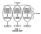
- Each FEC packet is associated to packets periodically selected. Therefore, consecutive RTP packets can be recovered from consecutive FEC packets as shown in Fig. 1 .
- the encoding scheme is schematized for L*D media packets.
- the period chosen is L.
- the payload of the kth FEC packet is computed based on the D packets numbered nL+k (0 ⁇ n ⁇ D-1).
- the main advantage of this scheme is the burst error correction capacity.
- the error correcting function chosen is XOR, which has the ability to recover anyone lost packet.
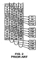
- the FEC packet FI protects data packets [1, 5, 9, 13, 17]
- FEC packet F6 protects data packets [6, 10, 14, 18, 22].
- Each FEC packet is transmitted L packet times after the last data packet it pertains to, creating a highly time-linear packet flow on the FEC stream.
- each individual column-FEC packet to indicate the base sequence number (SN-base), the offset (L) and a number of data packets (NA).
- Receivers can refer to these transmitted values in each FEC packet to correctly associated the FEC packet with the original data-stream packet group regardless of how the packets are staggered.
- WO 2005/0107123 discloses a method for transmitting digital data packets protected by error correction packets and more precisely the manner of inserting these correction packets into the data packet stream so as to increase the correction effectiveness of the error correction method while limiting the latency introduced into the transmission.
- the packets are set out in matrix form, error packets are computed on lines and columns and are inserted regularly into the stream at a sufficient distance from the data packets that they protest.
- the present invention is defined in claim 1.
- a system and method for transmitting an IP packet arranged in an LxD matrix comprising data packets and FEC packets, L corresponding to a number of columns in the matrix, and D corresponding to a number rows in the matrix includes assigning a first location in the matrix as an FEC packet location, skipping D number of locations in the matrix from the most recently assigned FEC packet location to a new location, and determining if the new location is positioned in the same column as an existing FEC packet location.
- the new location is assigned as an FEC packet location if it is determined that the new location is not positioned in the same column as an existing FEC packet location.
- the location is moved back in the matrix until the moved-back location is not positioned in the same column as an existing FEC packet location, and the moved-back location is assigned as an FEC packet location.
- the skipping, determining, assigning, and moving back are repeatedly performed until the number of FEC packet locations is equal to L.
- the FEC packets of the IP packet stream are transmitted in accordance with the identified FEC packet locations.
- FEC can be configured to work in accordance with "Period” columns (L) and “Order” rows (D).
- the data packets can be organized on a (Period x Order) grid with data packets transmitted in order from left-to-right, top-to-bottom.
- FEC packets are computed and transmitted as a block. These schemes transmit the grid's data as a block of (Period x Order) packets, and then they transmit Period number of FEC packets as a second block. This block-by-block transmission contributes to "bursty" data and timing difficulties with video. Interleaving the FEC packets with the data packets results in a more uniform distribution and improves the timing properties of MPEG video. However, simply spreading out the FEC packets results in increased latency and buffering required at the receiver. Thus, in addition, the blocks of data packets over which the FEC is computed are preferably staggered to match the distribution of the FEC packets.
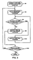
- Fig. 3 is a flow chart of an FEC staggering process consistent with the present invention. Using the process described by the flow chart shown in Fig. 3 , FEC packets are interspersed within the data packet stream but still transmitted immediately after the block of data they protect.
- the data grid packets are assigned sequential indexes, from 0 to (L*D-1), and an array can be built that specifies when to send an FEC packet.
- Fig. 3 the first FEC packet is placed in the first cell of the matrix (step S2).
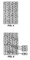
- An asterisk indicates where an FEC packet is to be inserted or interleaved. Accordingly, using the process of Fig. 3 , an asterisk is placed in cell al, which is the first cell of the matrix.
- step S4 a number of cells equal to D are skipped.
- the cells are skipped in the same order in which the packets are transmitted, i.e., from left to right and top to bottom. It is then checked if the cell resulting from skipping D cells is positioned in the same column as an existing FEC packet location (step S6). If not, the FEC packet is placed in the identified location (step S8).
- the number of FEC packet locations in an LxD matrix is equal to the period L. In the example of Fig. 4 , the period L is equal to four. Since at this point, only two FEC packet locations have been determined, D cells are again skipped to identify the location of the next FEC packet (step S4), and a check is repeated to determine if the identified location is positioned in the same column as an existing FEC packet (step S6). In this case, as shown in Fig. 4 , skipping six cells from b3 identifies cell dl. However, since there is already an FEC packet in the same column, i.e., at cell a1, the position of the next FEC packet is changed. Specifically, the cell position is backed up one spot to c4 (step S10).
- step S6 The check is repeated to determine if the identified location is positioned in the same column as an existing FEC packet. As shown in Fig. 4 , backing up one cell from dl identifies cell c4. Since there is not an existing FEC packet in the same column as cell c4, the next FEC packet is inserted at cell c4 (step S8).
- step S12 Since only three of the four FEC packet locations have been determined (step S12), D cells are again skipped to identify the location of the next FEC packet (step S4), and a check is repeated to determine if the identified location is positioned in the same column as an existing FEC packet (step S6). In this case, as shown in Fig. 4 , skipping six cells from c4 identifies cell e2. Since there is not an FEC packet in the same column as cell e2, the next FEC packet is inserted at cell e2 (step S8).
- the process has identified an FEC packet insertion location for each column of the matrix. Accordingly, no further locations need to be identified, and the same packet insertion locations can be used for each LxD matrix.
- each FEC packet includes correction data for a number of data packets D preceding the FEC packet insertion location in the same column. This is shown schematically in Fig. 5 .
- the FEC packet at cell a1 i.e., Fb1
- the FEC packet at cell a1 in Fig. 5 includes correction data for six data packets, which is the same number as the order D.
- the same situation applies for the FEC packets at cells Fc3, Fd4 and Ff2.
- the FEC packet can be transmitted by interleaving the FEC packet with the next data packet in that FEC packet's associated column. For example, the FEC packet at cell a1, Fb1, is transmitted at the "same time" as data packet b1.
- a Gigabit Ethernet interface 16 is utilized, which can support multiple channels of Video over IP (VIP) with Forward Error Correction (FEC). While various implementations are possible according to techniques known in the art, in this example a Field Programmable Gate Array (FPGA) 10 and a memory 20 are utilized.
- the memory can be implemented, for example, as a Synchronous Dynamic Random Access Memory (SDRAM), a nonvolatile RAM (NVRAM), or some other type of rewritable storage.
- SDRAM Synchronous Dynamic Random Access Memory
- NVRAM nonvolatile RAM
- a common "FEC engine” can be configured to process the many interleaved streams in accordance with the technique illustrated in Fig. 3 .
- This exemplary implementation allows the use of one "FEC engine” by many independent VIP channels.
- a parameter memory 12 in the FPGA stores the VIP channel parameters and state information. This allows each channel to have a unique set of configuration parameters for the Land D values.
- a VIP state machine 13 reads the parameters for the sending channel from the parameter memory 12.
- the VIP state machine 13 determines the FEC group to which the packet belongs, and instructs the memory controller 11 to fetch a partial FEC packet for that group from the memory 20.
- the IP packet received by the FPGA 10 is both buffered in a packet storage buffer 15 and processed by an FEC computation 14 with the partial FEC packet fetched from the memory 20.
- the FEC computation 14 processes the received IP packet and the partial FEC packet to generate a new partial FEC packet.
- the processing of the FEC computation 14 can be, for example, the result of an XOR operation between the received IP packet and the partial FEC packet.
- the result of the FEC computation 14 is written back into the memory 20 by the memory controller 11 as the next partial FEC packet.
- the VIP state machine 13 determines that the received packet is the last one in an FEC group. Once this is determined, instead of writing back the result of the FEC computation 14 into the memory 20, the result is sent to the packet storage buffer 15 as a completed FEC packet, and a clear partial FEC packet is written back to the memory 20. This operation serves to set up the start of the next group.
- the packet storage buffer 15 passes the packets to the Ethernet interface 16, which sends them out the Ethernet transmission channel.
- the VIP state machine 13 can be configured to maintain the following counters: "Period”: A counter that counts from 0 to (Lvalue - 1); "Order”: A counter that counts from 0 to (Dvalue - 1); and a series of "Group[N]" counters, one for each FEC group: Counts from 1 to Dvalue to indicate number of partial FEC packet computations completed so far for that group or contains a 0 indicating the group is still in the initialization stage. On initialization of a channel, Order, Period and all Group counter values are set to 0.
- FIG. 7 A flow chart of the VIP state machine 13 is shown in Fig. 7 , and the step-by-step operations for the example shown in Fig. 5 are shown in Fig. 8 .
- the VIP state machine waits for a new data packet to be ready for transmission (step S22). It then checks if the Group register indicated by the Period counter is zero (step S24). If not, it checks to see if it is equal to D, which is the length of the FEC group (step S26). If so, the completed FEC packet is sent to the packet buffer (step S34), and the Group counter is set to 1 (step S36). Otherwise, the partial FEC packet is written back to the memory 20 (step S28), and the Group counter is incremented (step S30). After either case, the Order counter is incremented by I between 0 and D-1 (step S32).
- step S24 If the Group counter was 0 (step S24), it indicates the group is still in the initialization state, and the following tests are done to determine if FEC packet generation should be started with this packet.
- the Order counter is checked to see if it is zero (step S38). If so, the Group counter is set to 1 (step S40), and the Order counter is set to 1 (step S42).
- the Order counter is checked to see if it currently has a value of D-1, and thus it will increment to 0 on the next packet (step S44). If not, the Order counter is incremented, and the Group counter is left as-is.
- step S48 a check is done to see if the next Group counter has been initialized
- step S50 the current one is also initialized by setting the Group counter to 1 (step S50), and the Order counter is set to a value of 1 (step S52). Finally, if all these tests fail, the group is left in the initialized state, and the Order counter is set to 0 (step S54).
- the Period counter is incremented by 1 in the range from 0 to L-1. To do so, a check is done to see if the Period counter is equal to L-1 (step S56). If so, the Period counter is set to 0 (step S60). If not, the Period counter is incremented by 1 (step S58). At that point the state machine waits for the next data packet to arrive (step S22).
Landscapes
- Engineering & Computer Science (AREA)
- Physics & Mathematics (AREA)
- Probability & Statistics with Applications (AREA)
- Theoretical Computer Science (AREA)
- Computer Networks & Wireless Communication (AREA)
- Signal Processing (AREA)
- Data Exchanges In Wide-Area Networks (AREA)
Description
- The present invention relates generally to video transmission and, more particularly, to a system and method for transmitting compressed video over IP networks using Forward Error Correction (FEC) packets to provide robust operation.
- Recently IP-based networks have become increasingly important for delivery of professional content, including video data. Errors in data transmission are generally not acceptable, which makes some sort of FEC scheme necessary.
- One issue with FEC systems on IP networks is that channel bit errors can result in packet losses. In addition, buffer and re-routing issues cause burst packet losses. The combination of packet losses from three sources - gross reordering, bit-error induced losses, and burst losses - is preferably low enough so that the FEC scheme is not broken more than the negotiated error rate. Because any bit errors cause the packet to be discarded, there is no requirement for an error correction scheme that can handle errored packets - every packet will either arrive correct or not at all.
- As disclosed by the Pro-MPEG Code of , an RTP payload format for Generic Forward Error Correction Packets has been defined in the RFC 2733 to enable error correction of real time media. This standard allows the use of traditional error correcting codes and can be used with any video format standards (e.g., MPEG, SDI, SDTI, etc.) as long as it is encapsulated in an RTP packet.
- To recover burst loss, the same traditional error correcting codes can be applied to non-consecutive media packets that can be spaced among many packets. Each FEC packet is associated to packets periodically selected. Therefore, consecutive RTP packets can be recovered from consecutive FEC packets as shown in
Fig. 1 . - In
Fig. 1 , the encoding scheme is schematized for L*D media packets. The period chosen is L. The payload of the kth FEC packet is computed based on the D packets numbered nL+k (0≤n≤D-1). The main advantage of this scheme is the burst error correction capacity. The error correcting function chosen is XOR, which has the ability to recover anyone lost packet. -
Figure 2 shows an example of a staggered arrangement for the case of (L=4, D=5). In this example, the FEC packet FI protects data packets [1, 5, 9, 13, 17], while FEC packet F6 protects data packets [6, 10, 14, 18, 22]. Each FEC packet is transmitted L packet times after the last data packet it pertains to, creating a highly time-linear packet flow on the FEC stream. - The standard requires each individual column-FEC packet to indicate the base sequence number (SN-base), the offset (L) and a number of data packets (NA). Receivers can refer to these transmitted values in each FEC packet to correctly associated the FEC packet with the original data-stream packet group regardless of how the packets are staggered.
- Although the Pro-MPEG Code of Practice #3 suggests the use of a "staggering" FEC scheme, it does not disclose or suggest how to implement such a scheme. It would therefore be desirable to have a "staggered" FEC scheme that can accommodate varying periods (i.e., L or number of columns) and orders (i.e., D or number of rows). This scheme should stagger the FEC columns in such a way that the resultant FEC packets are as evenly spaced as possible. A scheme such as this would result in minimal end-to-end latency and memory requirements in the receiver as well as provide a more uniform distribution of packets in the transmission channel.
-
WO 2005/0107123 - The present invention is defined in
claim 1. - According to an aspect of the invention, a system and method for transmitting an IP packet arranged in an LxD matrix comprising data packets and FEC packets, L corresponding to a number of columns in the matrix, and D corresponding to a number rows in the matrix includes assigning a first location in the matrix as an FEC packet location, skipping D number of locations in the matrix from the most recently assigned FEC packet location to a new location, and determining if the new location is positioned in the same column as an existing FEC packet location. The new location is assigned as an FEC packet location if it is determined that the new location is not positioned in the same column as an existing FEC packet location. If it is determined that the new location is positioned in the same column as an existing FEC packet location, then the location is moved back in the matrix until the moved-back location is not positioned in the same column as an existing FEC packet location, and the moved-back location is assigned as an FEC packet location. The skipping, determining, assigning, and moving back are repeatedly performed until the number of FEC packet locations is equal to L. The FEC packets of the IP packet stream are transmitted in accordance with the identified FEC packet locations.
- Further features, aspects and advantages of the present invention will become apparent from the detailed description of preferred embodiments that follows, when considered together with the accompanying figures of drawing.
-
Fig. 1 is an example of a conventional FEC encoding scheme. -
Fig. 2 is an example of a conventional FEC arrangement using staggering.Fig. 3 is a flow chart of an FEC packet process consistent with the present invention. -
Fig. 4 is an example of an FEC packet distribution in accordance with the process ofFig. 3 . -
Fig. 5 is an example of an FEC packet distribution in accordance with the process ofFig. 3 including a representation of the data packets associated with each FEC packet. -
Fig. 6 is a block diagram of an implementation of an FEC packet distribution system using the FEC packet process ofFig. 3 including a state machine for control. -
Fig. 7 is a flow chart for the operation of the state machine shown inFig. 6 . -
Fig. 8 is a list of the step-by-step operations for the example shown inFig. 5 using the process ofFig. 7 . - Using terminology from Pro-MPEG Code of
Practice # 3release 2, FEC can be configured to work in accordance with "Period" columns (L) and "Order" rows (D). The data packets can be organized on a (Period x Order) grid with data packets transmitted in order from left-to-right, top-to-bottom. - In some conventional schemes, FEC packets are computed and transmitted as a block. These schemes transmit the grid's data as a block of (Period x Order) packets, and then they transmit Period number of FEC packets as a second block. This block-by-block transmission contributes to "bursty" data and timing difficulties with video. Interleaving the FEC packets with the data packets results in a more uniform distribution and improves the timing properties of MPEG video. However, simply spreading out the FEC packets results in increased latency and buffering required at the receiver. Thus, in addition, the blocks of data packets over which the FEC is computed are preferably staggered to match the distribution of the FEC packets.
-
Fig. 3 is a flow chart of an FEC staggering process consistent with the present invention. Using the process described by the flow chart shown inFig. 3 , FEC packets are interspersed within the data packet stream but still transmitted immediately after the block of data they protect. The data grid packets are assigned sequential indexes, from 0 to (L*D-1), and an array can be built that specifies when to send an FEC packet. - As shown in
Fig. 3 , the first FEC packet is placed in the first cell of the matrix (step S2). By way of illustration,Fig. 4 is a schematic representation of a matrix in which the Period L=4 and the Order D=6. An asterisk indicates where an FEC packet is to be inserted or interleaved. Accordingly, using the process ofFig. 3 , an asterisk is placed in cell al, which is the first cell of the matrix. - To identify the placement of the next FEC packet, a number of cells equal to D are skipped (step S4). The cells are skipped in the same order in which the packets are transmitted, i.e., from left to right and top to bottom. It is then checked if the cell resulting from skipping D cells is positioned in the same column as an existing FEC packet location (step S6). If not, the FEC packet is placed in the identified location (step S8).
- As shown in
Fig. 4 in which D=6, skipping six cells corresponds to cell b3. Since there is not an existing FEC packet in the same column as cell b3, the next FEC packet is inserted at cell b3. - A check is then performed to determine if there are any remaining FEC packet locations (step S12). The number of FEC packet locations in an LxD matrix is equal to the period L. In the example of
Fig. 4 , the period L is equal to four. Since at this point, only two FEC packet locations have been determined, D cells are again skipped to identify the location of the next FEC packet (step S4), and a check is repeated to determine if the identified location is positioned in the same column as an existing FEC packet (step S6). In this case, as shown inFig. 4 , skipping six cells from b3 identifies cell dl. However, since there is already an FEC packet in the same column, i.e., at cell a1, the position of the next FEC packet is changed. Specifically, the cell position is backed up one spot to c4 (step S10). - The check is repeated to determine if the identified location is positioned in the same column as an existing FEC packet (step S6). As shown in
Fig. 4 , backing up one cell from dl identifies cell c4. Since there is not an existing FEC packet in the same column as cell c4, the next FEC packet is inserted at cell c4 (step S8). - Since only three of the four FEC packet locations have been determined (step S12), D cells are again skipped to identify the location of the next FEC packet (step S4), and a check is repeated to determine if the identified location is positioned in the same column as an existing FEC packet (step S6). In this case, as shown in
Fig. 4 , skipping six cells from c4 identifies cell e2. Since there is not an FEC packet in the same column as cell e2, the next FEC packet is inserted at cell e2 (step S8). - At this point, the process has identified an FEC packet insertion location for each column of the matrix. Accordingly, no further locations need to be identified, and the same packet insertion locations can be used for each LxD matrix.
- Based on the determined FEC packet insertion locations, it is possible to determine which data packets are used to generate each FEC packet. In general, each FEC packet includes correction data for a number of data packets D preceding the FEC packet insertion location in the same column. This is shown schematically in
Fig. 5 . As shown inFig. 5 , the FEC packet at cell a1 (i.e., Fb1) includes the correction data for the data packets at b1, c1, dl, e1, fl, and a1. Thus, the FEC packet at cell a1 inFig. 5 includes correction data for six data packets, which is the same number as the order D. The same situation applies for the FEC packets at cells Fc3, Fd4 and Ff2. During actual transmission, as shown inFig. 5 , the FEC packet can be transmitted by interleaving the FEC packet with the next data packet in that FEC packet's associated column. For example, the FEC packet at cell a1, Fb1, is transmitted at the "same time" as data packet b1. - It will be appreciated by those skilled in the art that this process may be implemented in a variety of systems. One example will now be described in reference to
Fig. 6 . - As illustrated generally in
Fig. 6 , aGigabit Ethernet interface 16 is utilized, which can support multiple channels of Video over IP (VIP) with Forward Error Correction (FEC). While various implementations are possible according to techniques known in the art, in this example a Field Programmable Gate Array (FPGA) 10 and amemory 20 are utilized. The memory can be implemented, for example, as a Synchronous Dynamic Random Access Memory (SDRAM), a nonvolatile RAM (NVRAM), or some other type of rewritable storage. Within theFPGA 10 and supporting firmware, a common "FEC engine" can be configured to process the many interleaved streams in accordance with the technique illustrated inFig. 3 . This exemplary implementation allows the use of one "FEC engine" by many independent VIP channels. As described below, aparameter memory 12 in the FPGA stores the VIP channel parameters and state information. This allows each channel to have a unique set of configuration parameters for the Land D values. - With reference to
Fig. 6 , when an IP packet for a particular channel is about to be transferred to theFPGA 10, aVIP state machine 13 reads the parameters for the sending channel from theparameter memory 12. TheVIP state machine 13 determines the FEC group to which the packet belongs, and instructs thememory controller 11 to fetch a partial FEC packet for that group from thememory 20. The IP packet received by theFPGA 10 is both buffered in apacket storage buffer 15 and processed by anFEC computation 14 with the partial FEC packet fetched from thememory 20. TheFEC computation 14 processes the received IP packet and the partial FEC packet to generate a new partial FEC packet. The processing of theFEC computation 14 can be, for example, the result of an XOR operation between the received IP packet and the partial FEC packet. The result of theFEC computation 14 is written back into thememory 20 by thememory controller 11 as the next partial FEC packet. - This process continues until the
VIP state machine 13 determines that the received packet is the last one in an FEC group. Once this is determined, instead of writing back the result of theFEC computation 14 into thememory 20, the result is sent to thepacket storage buffer 15 as a completed FEC packet, and a clear partial FEC packet is written back to thememory 20. This operation serves to set up the start of the next group. Thepacket storage buffer 15 passes the packets to theEthernet interface 16, which sends them out the Ethernet transmission channel. - In one embodiment, the
VIP state machine 13 can be configured to maintain the following counters: "Period": A counter that counts from 0 to (Lvalue - 1); "Order": A counter that counts from 0 to (Dvalue - 1); and a series of "Group[N]" counters, one for each FEC group: Counts from 1 to Dvalue to indicate number of partial FEC packet computations completed so far for that group or contains a 0 indicating the group is still in the initialization stage. On initialization of a channel, Order, Period and all Group counter values are set to 0. - A flow chart of the
VIP state machine 13 is shown inFig. 7 , and the step-by-step operations for the example shown inFig. 5 are shown inFig. 8 . After initializing the counters (step S20), the VIP state machine waits for a new data packet to be ready for transmission (step S22). It then checks if the Group register indicated by the Period counter is zero (step S24). If not, it checks to see if it is equal to D, which is the length of the FEC group (step S26). If so, the completed FEC packet is sent to the packet buffer (step S34), and the Group counter is set to 1 (step S36). Otherwise, the partial FEC packet is written back to the memory 20 (step S28), and the Group counter is incremented (step S30). After either case, the Order counter is incremented by I between 0 and D-1 (step S32). - If the Group counter was 0 (step S24), it indicates the group is still in the initialization state, and the following tests are done to determine if FEC packet generation should be started with this packet. First, the Order counter is checked to see if it is zero (step S38). If so, the Group counter is set to 1 (step S40), and the Order counter is set to 1 (step S42). Second, the Order counter is checked to see if it currently has a value of D-1, and thus it will increment to 0 on the next packet (step S44). If not, the Order counter is incremented, and the Group counter is left as-is. Third, a check is done to see if the next Group counter has been initialized (step S48). If so, the current one is also initialized by setting the Group counter to 1 (step S50), and the Order counter is set to a value of 1 (step S52). Finally, if all these tests fail, the group is left in the initialized state, and the Order counter is set to 0 (step S54).
- As a final step for all these operations, the Period counter is incremented by 1 in the range from 0 to L-1. To do so, a check is done to see if the Period counter is equal to L-1 (step S56). If so, the Period counter is set to 0 (step S60). If not, the Period counter is incremented by 1 (step S58). At that point the state machine waits for the next data packet to arrive (step S22).
Claims (8)
- A method for transmitting a group of IP packets arranged in an L by D matrix comprising LxD data packets and L number of FEC packets protecting columns of the matrix, L corresponding to a number of columns in the matrix, and D corresponding to a number rows in the matrix, wherein the packets are arranged in the same order in which they are transmitted, from the less significant position to the most significant position in each line and from the less significant line to the most significant line in the matrix the method comprising:a) assigning a first location in the matrix as an FEC packet location;b) moving forward D number of locations in the matrix from the most recently assigned FEC packet location to a new location;c) determining if the new location is positioned in the same column as an existing FEC packet location;d) assigning the new location as an FEC packet location if it is determined that the new location is not positioned in the same column as an existing FEC packet location;e) if it is determined that the new location is positioned in the same column as an existing FEC packet location, moving back in the matrix until the moved-back location is not positioned in the same column as an existing FEC packet location and assigning the moved-back location as an FEC packet location;f) repeating steps b)-e) until the number of FEC packet locations is equal to L; andg) transmitting the FEC packets by interleaving each FEC packet with the next data packet in that FEC packet's associated column.
- A method according to claim 1, further comprising: receiving a data packet; generating a partial FEC packet from the received data packet and a previously generated partial FEC packet; determining if the partial FEC packet has been generated from D number of data packets; transmitting the partial FEC packet as a complete FEC packet if the partial FEC packet has been generated from D number of data packets; and
storing the partial FEC packet in a memory if the partial FEC packet has been generated from less than D number of data packets . - A method according to claim 2, further comprising:maintaining a period counter that counts from 0 toL-1;maintaining an order counter that counts from 0 toD-1; andmaintaining L number of group counters, one for each FEC group, that counts from 1 to D to indicate number of partial FEC packet computations completed.
- A method according to claim 3, wherein the step of determining if the partial FEC packet has been generated from D number of data packets includes checking if the value of the group counter for the FEC group associated with the generated partial FEC packet is equal to D,
wherein the step of transmitting the partial FEC packet includes transmitting the partial FEC packet as the complete FEC packet if the value of the group counter for the FEC group associated with the generated partial FEC packet is equal to D, and
wherein the group counter for the FEC group associated with the generated partial FEC packet is incremented by one if the value of the group counter for the FEC group associated with the generated partial FEC packet is not equal to D. - A system for transmitting a group of IP packets arranged in an L by D matrix comprising LxD data packets and L number of FEC packets protecting columns of the matrix, L corresponding to a number of columns in the matrix, and D corresponding to a number rows in the matrix, wherein the packets are arranged in the same order in which they are transmitted, from the less significant position to the most significant position in each line and from the less significant line to the most significant line in the matrix the system comprising:a processor;a memory, coupled to the process or the memory comprising a plurality of instructions executed by the processor, the plurality of instructions configured to:a) assign a first location in the matrix as an FEC packet location;b) more forward D number of locations in the matrix from the most recently assigned FEC packet location to a new location;c) determine if the new location is positioned in the same column as an existing FEC packet location;d) assign the new location as an FEC packet location if it is determined that the new location is not positioned in the same column as an existing FEC packet location;e) if it is determined that the new location is positioned in the same column as an existing FEC packet location, move back in the matrix until the moved-back location is not positioned in the same column as an existing FEC packet location and assigning the moved-back location as an FEC packet location; andf) repeat b)- e) until the number of FEC packet locations is equal to L; andan interface configured to transmit the FEC packets of the IP packet by interleaving each FEC packet with the next data packet in that FEC, packet's associated column.
- A system according to claim 5, further comprising: a packet storage buffer that receives and stores a data packet;
an FEC computation unit that generates a partial FEC packet from the received data packet and a previously generated partial FEC packet;
a partial FEC packet memory that stores the partial FEC packet generated by the FEC computation unit if the partial FEC packet has been generated from less than D number of data packets;
wherein the interface transmits the partial FEC packet as a complete FEC packet if the partial FEC packet has been generated from D number of data packets. - A system according to claim 6, further comprising: a state machine configured to maintain a period counter that counts from 0 toL-1, an order counter that counts from 0 toD-1, and L number of group counters, one for each FEC group, that counts from 1 to D to indicate number of partial FEC packet computations completed, wherein the state machine increments and sets the value of the counters in accordance with received data packets and the FEC packet locations.
- A system according to claim 7, wherein the state machine is configured to check if the value of the group counter for the FEC group associated with the generated partial FEC packet is equal to D,
wherein the interface transmits the partial FEC packet as the complete FEC packet if the state machine determines that the value of the group counter for the FEC group associated with the generated partial FEC packet is equal to D, and
wherein state machine increments by one the group counter for the FEC group associated with the generated partial FEC packet if the value of the group counter for the FEC group associated with the generated partial FEC packet is not equal to D.
Applications Claiming Priority (2)
| Application Number | Priority Date | Filing Date | Title |
|---|---|---|---|
| US11/355,956 US7516387B2 (en) | 2006-02-17 | 2006-02-17 | System and method for transmitting FEC packets |
| PCT/US2007/003840 WO2007097952A2 (en) | 2006-02-17 | 2007-02-12 | System and method for transmitting fec packets |
Publications (3)
| Publication Number | Publication Date |
|---|---|
| EP1987598A2 EP1987598A2 (en) | 2008-11-05 |
| EP1987598A4 EP1987598A4 (en) | 2012-03-28 |
| EP1987598B1 true EP1987598B1 (en) | 2013-07-10 |
Family
ID=38437858
Family Applications (1)
| Application Number | Title | Priority Date | Filing Date |
|---|---|---|---|
| EP07750662.4A Active EP1987598B1 (en) | 2006-02-17 | 2007-02-12 | System and method for transmitting fec packets |
Country Status (3)
| Country | Link |
|---|---|
| US (1) | US7516387B2 (en) |
| EP (1) | EP1987598B1 (en) |
| WO (1) | WO2007097952A2 (en) |
Families Citing this family (17)
| Publication number | Priority date | Publication date | Assignee | Title |
|---|---|---|---|---|
| US7533324B2 (en) * | 2004-09-22 | 2009-05-12 | Kencast, Inc. | System, method and apparatus for FEC encoding and decoding |
| US7739580B1 (en) | 2005-02-17 | 2010-06-15 | Kencast, Inc. | System, method and apparatus for reducing blockage losses on information distribution networks |
| US8223643B1 (en) | 2005-09-06 | 2012-07-17 | Kencast, Inc. | Method for packet-level FEC encoding a stream of source packets using shifted interleaving |
| US7577898B2 (en) * | 2006-04-10 | 2009-08-18 | At&T Intellectual Property I, L.P. | System and method of correcting video data errors |
| US8707139B2 (en) | 2006-10-18 | 2014-04-22 | Kencast, Inc. | Systems, methods, apparatus, and computer program products for providing forward error correction with low latency |
| WO2008097027A1 (en) * | 2007-02-07 | 2008-08-14 | Lg Electronics Inc. | Digital broadcasting system and method of processing data |
| US8418034B2 (en) * | 2008-02-08 | 2013-04-09 | Kencast, Inc. | Systems, methods, apparatus and computer program products for highly reliable file delivery using compound and braided FEC encoding and decoding |
| JP5412917B2 (en) * | 2009-03-27 | 2014-02-12 | 富士通株式会社 | Error correction control apparatus, error correction control method, and media data distribution system |
| JP5377040B2 (en) * | 2009-04-08 | 2013-12-25 | キヤノン株式会社 | Transmitting apparatus and transmitting method |
| US8653819B2 (en) * | 2009-09-08 | 2014-02-18 | California Institute Of Technology | Technique for performing dielectric property measurements at microwave frequencies |
| US10216647B2 (en) * | 2010-02-27 | 2019-02-26 | International Business Machines Corporation | Compacting dispersed storage space |
| US11429486B1 (en) | 2010-02-27 | 2022-08-30 | Pure Storage, Inc. | Rebuilding data via locally decodable redundancy in a vast storage network |
| US8972815B1 (en) * | 2012-03-20 | 2015-03-03 | Xilinx, Inc. | Recovery of media datagrams |
| US9967306B1 (en) * | 2016-09-08 | 2018-05-08 | Sprint Spectrum L.P. | Prioritized transmission of redundancy data for packetized voice communication |
| US10594661B1 (en) * | 2017-06-13 | 2020-03-17 | Parallels International Gmbh | System and method for recovery of data packets transmitted over an unreliable network |
| US10771191B2 (en) | 2018-03-09 | 2020-09-08 | Kencast, Inc. | System for highly reliable file delivery of using continuous FEC encoding/decoding |
| CN118869153B (en) * | 2024-09-24 | 2024-12-03 | 中茵微电子(南京)有限公司 | A Scheduling and Flow Control Method Based on FEC Coding Direction |
Family Cites Families (5)
| Publication number | Priority date | Publication date | Assignee | Title |
|---|---|---|---|---|
| US6745364B2 (en) * | 2001-06-28 | 2004-06-01 | Microsoft Corporation | Negotiated/dynamic error correction for streamed media |
| US7155532B2 (en) * | 2002-01-04 | 2006-12-26 | Scientific-Atlanta, Inc. | Transmitting streams over asynchronous networks |
| JP4454320B2 (en) * | 2004-01-09 | 2010-04-21 | 富士通株式会社 | Transmission apparatus, transmission control program, and transmission method |
| FR2869744A1 (en) * | 2004-04-29 | 2005-11-04 | Thomson Licensing Sa | METHOD FOR TRANSMITTING DIGITAL DATA PACKETS AND APPARATUS IMPLEMENTING THE METHOD |
| JP4405875B2 (en) * | 2004-08-25 | 2010-01-27 | 富士通株式会社 | Method and apparatus for generating data for error correction, generation program, and computer-readable recording medium storing the program |
-
2006
- 2006-02-17 US US11/355,956 patent/US7516387B2/en active Active
-
2007
- 2007-02-12 WO PCT/US2007/003840 patent/WO2007097952A2/en not_active Ceased
- 2007-02-12 EP EP07750662.4A patent/EP1987598B1/en active Active
Also Published As
| Publication number | Publication date |
|---|---|
| US7516387B2 (en) | 2009-04-07 |
| EP1987598A2 (en) | 2008-11-05 |
| WO2007097952A2 (en) | 2007-08-30 |
| US20070220405A1 (en) | 2007-09-20 |
| WO2007097952A3 (en) | 2008-10-16 |
| EP1987598A4 (en) | 2012-03-28 |
Similar Documents
| Publication | Publication Date | Title |
|---|---|---|
| WO2007097952A2 (en) | System and method for transmitting fec packets | |
| JP4785836B2 (en) | Method for transmitting digital data packets and apparatus for implementing the method | |
| EP2103026B1 (en) | A method to support forward error correction for real-time audio and video data over internet protocol networks | |
| US5742612A (en) | Method and device for interleaving a sequence of data elements | |
| US9130594B2 (en) | Continuously interleaved error correction | |
| EP2031787A2 (en) | FEC transmission processing apparatus and method and program recording medium | |
| CN1871803B (en) | Method and bearer device for lost packet reconstruction | |
| KR20120029776A (en) | Rate matching apparatus and method rate matching thereof | |
| US6901550B2 (en) | Two-dimensional interleaving in a modem pool environment | |
| US8223643B1 (en) | Method for packet-level FEC encoding a stream of source packets using shifted interleaving | |
| US8279741B2 (en) | Device and method for interleaved encoding RS code | |
| US6055663A (en) | Error-robust multiplex process with header control field | |
| EP1758254A1 (en) | Improved erasure correction scheme based on XOR operations for packet transmission | |
| EP2541778A1 (en) | Interleaving device and interleaving method | |
| US20080250298A1 (en) | Protocol extensions to support varying fec types | |
| JP2016092632A (en) | Data transmission / reception system, data transmission device, data reception device, data transmission / reception method, and program | |
| DE10109338A1 (en) | Radio transmission of bit sequence using UMTS third generation mode, groups bits into b-bit data symbols which are encoded systematically, with added redundancy | |
| KR20050064486A (en) | Method for block interleaving in cdma mobile communication system |
Legal Events
| Date | Code | Title | Description |
|---|---|---|---|
| PUAI | Public reference made under article 153(3) epc to a published international application that has entered the european phase |
Free format text: ORIGINAL CODE: 0009012 |
|
| 17P | Request for examination filed |
Effective date: 20080910 |
|
| AK | Designated contracting states |
Kind code of ref document: A2 Designated state(s): AT BE BG CH CY CZ DE DK EE ES FI FR GB GR HU IE IS IT LI LT LU LV MC NL PL PT RO SE SI SK TR |
|
| AX | Request for extension of the european patent |
Extension state: AL BA HR MK RS |
|
| R17D | Deferred search report published (corrected) |
Effective date: 20081016 |
|
| A4 | Supplementary search report drawn up and despatched |
Effective date: 20120224 |
|
| RIC1 | Information provided on ipc code assigned before grant |
Ipc: H03M 13/27 20060101AFI20120220BHEP Ipc: H04L 1/00 20060101ALI20120220BHEP Ipc: H03M 13/37 20060101ALI20120220BHEP |
|
| DAX | Request for extension of the european patent (deleted) | ||
| REG | Reference to a national code |
Ref country code: DE Ref legal event code: R079 Ref document number: 602007031555 Country of ref document: DE Free format text: PREVIOUS MAIN CLASS: H03M0013000000 Ipc: H03M0013270000 |
|
| GRAP | Despatch of communication of intention to grant a patent |
Free format text: ORIGINAL CODE: EPIDOSNIGR1 |
|
| RIC1 | Information provided on ipc code assigned before grant |
Ipc: H03M 13/27 20060101AFI20120904BHEP Ipc: H04L 1/00 20060101ALI20120904BHEP Ipc: H03M 13/37 20060101ALI20120904BHEP |
|
| GRAS | Grant fee paid |
Free format text: ORIGINAL CODE: EPIDOSNIGR3 |
|
| GRAP | Despatch of communication of intention to grant a patent |
Free format text: ORIGINAL CODE: EPIDOSNIGR1 |
|
| RAP1 | Party data changed (applicant data changed or rights of an application transferred) |
Owner name: HBC SOLUTIONS, INC. |
|
| GRAA | (expected) grant |
Free format text: ORIGINAL CODE: 0009210 |
|
| AK | Designated contracting states |
Kind code of ref document: B1 Designated state(s): AT BE BG CH CY CZ DE DK EE ES FI FR GB GR HU IE IS IT LI LT LU LV MC NL PL PT RO SE SI SK TR |
|
| REG | Reference to a national code |
Ref country code: GB Ref legal event code: FG4D |
|
| REG | Reference to a national code |
Ref country code: AT Ref legal event code: REF Ref document number: 621457 Country of ref document: AT Kind code of ref document: T Effective date: 20130715 Ref country code: CH Ref legal event code: EP |
|
| REG | Reference to a national code |
Ref country code: IE Ref legal event code: FG4D |
|
| REG | Reference to a national code |
Ref country code: DE Ref legal event code: R096 Ref document number: 602007031555 Country of ref document: DE Effective date: 20130905 |
|
| REG | Reference to a national code |
Ref country code: SE Ref legal event code: TRGR |
|
| PG25 | Lapsed in a contracting state [announced via postgrant information from national office to epo] |
Ref country code: SI Free format text: LAPSE BECAUSE OF FAILURE TO SUBMIT A TRANSLATION OF THE DESCRIPTION OR TO PAY THE FEE WITHIN THE PRESCRIBED TIME-LIMIT Effective date: 20130710 |
|
| REG | Reference to a national code |
Ref country code: AT Ref legal event code: MK05 Ref document number: 621457 Country of ref document: AT Kind code of ref document: T Effective date: 20130710 |
|
| REG | Reference to a national code |
Ref country code: NL Ref legal event code: VDEP Effective date: 20130710 |
|
| REG | Reference to a national code |
Ref country code: LT Ref legal event code: MG4D |
|
| PG25 | Lapsed in a contracting state [announced via postgrant information from national office to epo] |
Ref country code: LT Free format text: LAPSE BECAUSE OF FAILURE TO SUBMIT A TRANSLATION OF THE DESCRIPTION OR TO PAY THE FEE WITHIN THE PRESCRIBED TIME-LIMIT Effective date: 20130710 Ref country code: AT Free format text: LAPSE BECAUSE OF FAILURE TO SUBMIT A TRANSLATION OF THE DESCRIPTION OR TO PAY THE FEE WITHIN THE PRESCRIBED TIME-LIMIT Effective date: 20130710 Ref country code: PT Free format text: LAPSE BECAUSE OF FAILURE TO SUBMIT A TRANSLATION OF THE DESCRIPTION OR TO PAY THE FEE WITHIN THE PRESCRIBED TIME-LIMIT Effective date: 20131111 Ref country code: CY Free format text: LAPSE BECAUSE OF FAILURE TO SUBMIT A TRANSLATION OF THE DESCRIPTION OR TO PAY THE FEE WITHIN THE PRESCRIBED TIME-LIMIT Effective date: 20130619 Ref country code: IS Free format text: LAPSE BECAUSE OF FAILURE TO SUBMIT A TRANSLATION OF THE DESCRIPTION OR TO PAY THE FEE WITHIN THE PRESCRIBED TIME-LIMIT Effective date: 20131110 Ref country code: BE Free format text: LAPSE BECAUSE OF FAILURE TO SUBMIT A TRANSLATION OF THE DESCRIPTION OR TO PAY THE FEE WITHIN THE PRESCRIBED TIME-LIMIT Effective date: 20130710 |
|
| PG25 | Lapsed in a contracting state [announced via postgrant information from national office to epo] |
Ref country code: GR Free format text: LAPSE BECAUSE OF FAILURE TO SUBMIT A TRANSLATION OF THE DESCRIPTION OR TO PAY THE FEE WITHIN THE PRESCRIBED TIME-LIMIT Effective date: 20131011 Ref country code: PL Free format text: LAPSE BECAUSE OF FAILURE TO SUBMIT A TRANSLATION OF THE DESCRIPTION OR TO PAY THE FEE WITHIN THE PRESCRIBED TIME-LIMIT Effective date: 20130710 Ref country code: LV Free format text: LAPSE BECAUSE OF FAILURE TO SUBMIT A TRANSLATION OF THE DESCRIPTION OR TO PAY THE FEE WITHIN THE PRESCRIBED TIME-LIMIT Effective date: 20130710 Ref country code: NL Free format text: LAPSE BECAUSE OF FAILURE TO SUBMIT A TRANSLATION OF THE DESCRIPTION OR TO PAY THE FEE WITHIN THE PRESCRIBED TIME-LIMIT Effective date: 20130710 Ref country code: ES Free format text: LAPSE BECAUSE OF FAILURE TO SUBMIT A TRANSLATION OF THE DESCRIPTION OR TO PAY THE FEE WITHIN THE PRESCRIBED TIME-LIMIT Effective date: 20131021 Ref country code: FI Free format text: LAPSE BECAUSE OF FAILURE TO SUBMIT A TRANSLATION OF THE DESCRIPTION OR TO PAY THE FEE WITHIN THE PRESCRIBED TIME-LIMIT Effective date: 20130710 |
|
| PG25 | Lapsed in a contracting state [announced via postgrant information from national office to epo] |
Ref country code: CY Free format text: LAPSE BECAUSE OF FAILURE TO SUBMIT A TRANSLATION OF THE DESCRIPTION OR TO PAY THE FEE WITHIN THE PRESCRIBED TIME-LIMIT Effective date: 20130710 |
|
| PG25 | Lapsed in a contracting state [announced via postgrant information from national office to epo] |
Ref country code: RO Free format text: LAPSE BECAUSE OF FAILURE TO SUBMIT A TRANSLATION OF THE DESCRIPTION OR TO PAY THE FEE WITHIN THE PRESCRIBED TIME-LIMIT Effective date: 20130710 Ref country code: CZ Free format text: LAPSE BECAUSE OF FAILURE TO SUBMIT A TRANSLATION OF THE DESCRIPTION OR TO PAY THE FEE WITHIN THE PRESCRIBED TIME-LIMIT Effective date: 20130710 Ref country code: DK Free format text: LAPSE BECAUSE OF FAILURE TO SUBMIT A TRANSLATION OF THE DESCRIPTION OR TO PAY THE FEE WITHIN THE PRESCRIBED TIME-LIMIT Effective date: 20130710 Ref country code: EE Free format text: LAPSE BECAUSE OF FAILURE TO SUBMIT A TRANSLATION OF THE DESCRIPTION OR TO PAY THE FEE WITHIN THE PRESCRIBED TIME-LIMIT Effective date: 20130710 Ref country code: SK Free format text: LAPSE BECAUSE OF FAILURE TO SUBMIT A TRANSLATION OF THE DESCRIPTION OR TO PAY THE FEE WITHIN THE PRESCRIBED TIME-LIMIT Effective date: 20130710 |
|
| PLBE | No opposition filed within time limit |
Free format text: ORIGINAL CODE: 0009261 |
|
| STAA | Information on the status of an ep patent application or granted ep patent |
Free format text: STATUS: NO OPPOSITION FILED WITHIN TIME LIMIT |
|
| PG25 | Lapsed in a contracting state [announced via postgrant information from national office to epo] |
Ref country code: IT Free format text: LAPSE BECAUSE OF FAILURE TO SUBMIT A TRANSLATION OF THE DESCRIPTION OR TO PAY THE FEE WITHIN THE PRESCRIBED TIME-LIMIT Effective date: 20130710 |
|
| 26N | No opposition filed |
Effective date: 20140411 |
|
| REG | Reference to a national code |
Ref country code: DE Ref legal event code: R097 Ref document number: 602007031555 Country of ref document: DE Effective date: 20140411 |
|
| PG25 | Lapsed in a contracting state [announced via postgrant information from national office to epo] |
Ref country code: LU Free format text: LAPSE BECAUSE OF FAILURE TO SUBMIT A TRANSLATION OF THE DESCRIPTION OR TO PAY THE FEE WITHIN THE PRESCRIBED TIME-LIMIT Effective date: 20140212 Ref country code: MC Free format text: LAPSE BECAUSE OF FAILURE TO SUBMIT A TRANSLATION OF THE DESCRIPTION OR TO PAY THE FEE WITHIN THE PRESCRIBED TIME-LIMIT Effective date: 20130710 |
|
| REG | Reference to a national code |
Ref country code: CH Ref legal event code: PL |
|
| PG25 | Lapsed in a contracting state [announced via postgrant information from national office to epo] |
Ref country code: CH Free format text: LAPSE BECAUSE OF NON-PAYMENT OF DUE FEES Effective date: 20140228 Ref country code: LI Free format text: LAPSE BECAUSE OF NON-PAYMENT OF DUE FEES Effective date: 20140228 |
|
| REG | Reference to a national code |
Ref country code: IE Ref legal event code: MM4A |
|
| PG25 | Lapsed in a contracting state [announced via postgrant information from national office to epo] |
Ref country code: IE Free format text: LAPSE BECAUSE OF NON-PAYMENT OF DUE FEES Effective date: 20140212 |
|
| REG | Reference to a national code |
Ref country code: FR Ref legal event code: PLFP Year of fee payment: 10 |
|
| PG25 | Lapsed in a contracting state [announced via postgrant information from national office to epo] |
Ref country code: BG Free format text: LAPSE BECAUSE OF FAILURE TO SUBMIT A TRANSLATION OF THE DESCRIPTION OR TO PAY THE FEE WITHIN THE PRESCRIBED TIME-LIMIT Effective date: 20130710 |
|
| PG25 | Lapsed in a contracting state [announced via postgrant information from national office to epo] |
Ref country code: TR Free format text: LAPSE BECAUSE OF FAILURE TO SUBMIT A TRANSLATION OF THE DESCRIPTION OR TO PAY THE FEE WITHIN THE PRESCRIBED TIME-LIMIT Effective date: 20130710 Ref country code: HU Free format text: LAPSE BECAUSE OF FAILURE TO SUBMIT A TRANSLATION OF THE DESCRIPTION OR TO PAY THE FEE WITHIN THE PRESCRIBED TIME-LIMIT; INVALID AB INITIO Effective date: 20070212 |
|
| REG | Reference to a national code |
Ref country code: FR Ref legal event code: PLFP Year of fee payment: 11 |
|
| REG | Reference to a national code |
Ref country code: DE Ref legal event code: R082 Ref document number: 602007031555 Country of ref document: DE Representative=s name: WUESTHOFF & WUESTHOFF, PATENTANWAELTE PARTG MB, DE Ref country code: DE Ref legal event code: R081 Ref document number: 602007031555 Country of ref document: DE Owner name: IMAGINE COMMUNICATIONS CORP., FRISCO, US Free format text: FORMER OWNER: HBC SOLUTIONS, INC., ENGLEWOOD, COL., US |
|
| REG | Reference to a national code |
Ref country code: FR Ref legal event code: CA Effective date: 20171227 Ref country code: FR Ref legal event code: CD Owner name: IMAGINE COMMUNICATIONS CORP., US Effective date: 20171227 |
|
| REG | Reference to a national code |
Ref country code: FR Ref legal event code: PLFP Year of fee payment: 12 |
|
| PGFP | Annual fee paid to national office [announced via postgrant information from national office to epo] |
Ref country code: SE Payment date: 20260227 Year of fee payment: 20 |
|
| PGFP | Annual fee paid to national office [announced via postgrant information from national office to epo] |
Ref country code: GB Payment date: 20260227 Year of fee payment: 20 |
|
| PGFP | Annual fee paid to national office [announced via postgrant information from national office to epo] |
Ref country code: DE Payment date: 20260227 Year of fee payment: 20 |
|
| PGFP | Annual fee paid to national office [announced via postgrant information from national office to epo] |
Ref country code: FR Payment date: 20260225 Year of fee payment: 20 |