EP1986554B1 - Gewebeklammer - Google Patents
Gewebeklammer Download PDFInfo
- Publication number
- EP1986554B1 EP1986554B1 EP07762739.6A EP07762739A EP1986554B1 EP 1986554 B1 EP1986554 B1 EP 1986554B1 EP 07762739 A EP07762739 A EP 07762739A EP 1986554 B1 EP1986554 B1 EP 1986554B1
- Authority
- EP
- European Patent Office
- Prior art keywords
- tissue
- tack
- combination according
- arms
- barrel
- Prior art date
- Legal status (The legal status is an assumption and is not a legal conclusion. Google has not performed a legal analysis and makes no representation as to the accuracy of the status listed.)
- Active
Links
Images


Classifications
-
- A—HUMAN NECESSITIES
- A61—MEDICAL OR VETERINARY SCIENCE; HYGIENE
- A61B—DIAGNOSIS; SURGERY; IDENTIFICATION
- A61B17/00—Surgical instruments, devices or methods
- A61B17/04—Surgical instruments, devices or methods for suturing wounds; Holders or packages for needles or suture materials
- A61B17/0401—Suture anchors, buttons or pledgets, i.e. means for attaching sutures to bone, cartilage or soft tissue; Instruments for applying or removing suture anchors
-
- A—HUMAN NECESSITIES
- A61—MEDICAL OR VETERINARY SCIENCE; HYGIENE
- A61B—DIAGNOSIS; SURGERY; IDENTIFICATION
- A61B17/00—Surgical instruments, devices or methods
- A61B17/064—Surgical staples, i.e. penetrating the tissue
-
- A—HUMAN NECESSITIES
- A61—MEDICAL OR VETERINARY SCIENCE; HYGIENE
- A61B—DIAGNOSIS; SURGERY; IDENTIFICATION
- A61B17/00—Surgical instruments, devices or methods
- A61B17/064—Surgical staples, i.e. penetrating the tissue
- A61B17/0644—Surgical staples, i.e. penetrating the tissue penetrating the tissue, deformable to closed position
-
- A—HUMAN NECESSITIES
- A61—MEDICAL OR VETERINARY SCIENCE; HYGIENE
- A61B—DIAGNOSIS; SURGERY; IDENTIFICATION
- A61B17/00—Surgical instruments, devices or methods
- A61B17/068—Surgical staplers, e.g. containing multiple staples or clamps
-
- A—HUMAN NECESSITIES
- A61—MEDICAL OR VETERINARY SCIENCE; HYGIENE
- A61B—DIAGNOSIS; SURGERY; IDENTIFICATION
- A61B17/00—Surgical instruments, devices or methods
- A61B17/04—Surgical instruments, devices or methods for suturing wounds; Holders or packages for needles or suture materials
- A61B17/0469—Suturing instruments for use in minimally invasive surgery, e.g. endoscopic surgery
-
- A—HUMAN NECESSITIES
- A61—MEDICAL OR VETERINARY SCIENCE; HYGIENE
- A61B—DIAGNOSIS; SURGERY; IDENTIFICATION
- A61B17/00—Surgical instruments, devices or methods
- A61B2017/00831—Material properties
- A61B2017/00862—Material properties elastic or resilient
-
- A—HUMAN NECESSITIES
- A61—MEDICAL OR VETERINARY SCIENCE; HYGIENE
- A61B—DIAGNOSIS; SURGERY; IDENTIFICATION
- A61B17/00—Surgical instruments, devices or methods
- A61B17/04—Surgical instruments, devices or methods for suturing wounds; Holders or packages for needles or suture materials
- A61B17/0401—Suture anchors, buttons or pledgets, i.e. means for attaching sutures to bone, cartilage or soft tissue; Instruments for applying or removing suture anchors
- A61B2017/0409—Instruments for applying suture anchors
-
- A—HUMAN NECESSITIES
- A61—MEDICAL OR VETERINARY SCIENCE; HYGIENE
- A61B—DIAGNOSIS; SURGERY; IDENTIFICATION
- A61B17/00—Surgical instruments, devices or methods
- A61B17/04—Surgical instruments, devices or methods for suturing wounds; Holders or packages for needles or suture materials
- A61B17/0401—Suture anchors, buttons or pledgets, i.e. means for attaching sutures to bone, cartilage or soft tissue; Instruments for applying or removing suture anchors
- A61B2017/0412—Suture anchors, buttons or pledgets, i.e. means for attaching sutures to bone, cartilage or soft tissue; Instruments for applying or removing suture anchors having anchoring barbs or pins extending outwardly from suture anchor body
-
- A—HUMAN NECESSITIES
- A61—MEDICAL OR VETERINARY SCIENCE; HYGIENE
- A61B—DIAGNOSIS; SURGERY; IDENTIFICATION
- A61B17/00—Surgical instruments, devices or methods
- A61B17/04—Surgical instruments, devices or methods for suturing wounds; Holders or packages for needles or suture materials
- A61B17/0401—Suture anchors, buttons or pledgets, i.e. means for attaching sutures to bone, cartilage or soft tissue; Instruments for applying or removing suture anchors
- A61B2017/0427—Suture anchors, buttons or pledgets, i.e. means for attaching sutures to bone, cartilage or soft tissue; Instruments for applying or removing suture anchors having anchoring barbs or pins extending outwardly from the anchor body
- A61B2017/0437—Suture anchors, buttons or pledgets, i.e. means for attaching sutures to bone, cartilage or soft tissue; Instruments for applying or removing suture anchors having anchoring barbs or pins extending outwardly from the anchor body the barbs being resilient or spring-like
-
- A—HUMAN NECESSITIES
- A61—MEDICAL OR VETERINARY SCIENCE; HYGIENE
- A61B—DIAGNOSIS; SURGERY; IDENTIFICATION
- A61B17/00—Surgical instruments, devices or methods
- A61B17/04—Surgical instruments, devices or methods for suturing wounds; Holders or packages for needles or suture materials
- A61B17/0401—Suture anchors, buttons or pledgets, i.e. means for attaching sutures to bone, cartilage or soft tissue; Instruments for applying or removing suture anchors
- A61B2017/0464—Suture anchors, buttons or pledgets, i.e. means for attaching sutures to bone, cartilage or soft tissue; Instruments for applying or removing suture anchors for soft tissue
-
- A—HUMAN NECESSITIES
- A61—MEDICAL OR VETERINARY SCIENCE; HYGIENE
- A61B—DIAGNOSIS; SURGERY; IDENTIFICATION
- A61B17/00—Surgical instruments, devices or methods
- A61B17/28—Surgical forceps
- A61B17/29—Forceps for use in minimally invasive surgery
- A61B2017/2901—Details of shaft
- A61B2017/2905—Details of shaft flexible
-
- A—HUMAN NECESSITIES
- A61—MEDICAL OR VETERINARY SCIENCE; HYGIENE
- A61B—DIAGNOSIS; SURGERY; IDENTIFICATION
- A61B90/00—Instruments, implements or accessories specially adapted for surgery or diagnosis and not covered by any of the groups A61B1/00 - A61B50/00, e.g. for luxation treatment or for protecting wound edges
- A61B90/39—Markers, e.g. radio-opaque or breast lesions markers
- A61B2090/3925—Markers, e.g. radio-opaque or breast lesions markers ultrasonic
-
- A—HUMAN NECESSITIES
- A61—MEDICAL OR VETERINARY SCIENCE; HYGIENE
- A61B—DIAGNOSIS; SURGERY; IDENTIFICATION
- A61B90/00—Instruments, implements or accessories specially adapted for surgery or diagnosis and not covered by any of the groups A61B1/00 - A61B50/00, e.g. for luxation treatment or for protecting wound edges
- A61B90/39—Markers, e.g. radio-opaque or breast lesions markers
Definitions
- the present invention relates to surgical devices. More specifically, the present invention relates to surgical devices for closing incisions, and fastening tissues and prostheses.
- Minimally invasive surgery has allowed physicians to carry out many surgical procedures with less pain and disability than conventional, open surgery.
- the surgeon makes a number of small incisions through the body wall to obtain access to the tissues requiring treatment.
- a trocar which is a pointed, piercing device, is delivered into the body with a cannula. After the trocar pierces the abdominal or thoracic wall, it is removed and the cannula is left with one end in the body cavity, where the operation is to take place, and the other end opening to the outside.
- a cannula has a small inside diameter, generally 3-10 millimeters. A number of such cannulas are inserted for any given operation.
- a viewing instrument typically including a miniaturized video camera, is inserted through one of these cannulas and a variety of surgical instruments and retractors are inserted through others.
- the image provided by the viewing device may be displayed on a video screen or television monitor, affording the surgeon enhanced visual control over the instruments.
- a commonly used viewing instrument is called an "endoscope,” this type of surgery is often referred to as “endoscopic surgery.”
- endoscopic procedures In the abdomen, endoscopic procedures are commonly referred to as laparoscopic surgery, and in the chest, as thoracoscopic surgery.
- Abdominal procedures may take place either inside the abdominal cavity (in the intraperitoneal space) or in a space created behind the abdominal cavity (in the retroperitoneal space). The retroperitoneal space is particularly useful for operations on the aorta and spine.
- vascular surgery has virtually replaced open surgical techniques for operations such as cholecystectomy and anti-reflux surgery of the esophagus and stomach. This has not occurred in either peripheral vascular surgery or cardiovascular surgery.
- An important type of vascular surgery is to replace or bypass a diseased, occluded or injured artery.
- Arterial replacement or bypass grafting has been performed for many years using open surgical techniques and a variety of prosthetic grafts. These grafts are manufactured as fabrics (often from Dacron or Teflon) or are prepared as autografts (from the patient's own tissues) or heterografts (from the tissues of animals).
- a graft can be joined to the involved artery in a number of different positions, including end-to-end, end-to-side, and side-to-side. This attachment between artery and graft is known as an anastomosis. Constructing an arterial anastomosis is technically challenging for a surgeon in open surgical procedures, and is almost a technical impossibility using minimally invasive techniques.
- Minimally invasive surgery is of interest in cardiovascular surgery because of the nature of the tissue of the heart.
- Cells known as myocytes beat together in unison in a healthy heart when ion channels open and close in an organized manner. Ions pass in and out of the channels, and the change in concentration of ions from within a cell to outside of a cell results in an electrical potential, causing the cell itself to depolarize and repolarize. The depolarization of one cell triggers the cell next to it to depolarize, and thus a cascade effect of depolarization of all the myocytes is triggered and the heart beats. Making several incisions can interrupt this cascade during surgery and change the beating of the heart. Keeping incisions to a minimum with minimally invasive techniques will allow beating heart surgery to be successful while maintaining the electrical integrity of the heart.
- the arteries subject to peripheral vascular and cardiovascular surgery typically range in diameter from several millimeters to several centimeters.
- a graft is typically about the same size as the artery to which it is being attached.
- Another factor contributing to the difficulty of such procedures is the limited time available to complete the procedure. The time the surgeon has to complete an arterial replacement or bypass graft is limited because there is no blood flowing through the artery while the procedure is being done. If blood flow is not promptly restored, sometimes in as little as thirty minutes, the tissue the artery supplies may experience significant damage, or even death (tissue necrosis).
- arterial replacement or bypass grafting is made more difficult by the need to accurately place and space many sutures to achieve a permanent hemostatic seal. Precise placement and spacing of sutures is also required to achieve an anastomosis with long-term patency.
- a suture has a suture needle that is attached or "swedged on" to a long, trailing suture material.
- the needle must be precisely controlled and accurately placed through both graft and artery.
- the trailing suture material must be held with proper tension to keep the graft and artery together, and must be carefully manipulated to prevent the suture material from tangling. In open surgery, these maneuvers can usually be accomplished within the necessary time frame, thus avoiding the subsequent tissue damage (or tissue death) that can result from prolonged occlusion of arterial blood flow.
- anastomoses are commonly formed in open surgery by suturing together the tissues to be joined.
- one known system for applying a clip around tissues to be joined in an anastomosis is disclosed in a brochure entitled, " VCS Clip Applier System", published in 1995 by Auto Suture Company, a Division of U.S. Surgical Corporati on.
- a clip is applied by an applying instrument about the tissues in a nonpenetrating manner, i.e., the clip does not penetrate through the tissues, but rather is clamped down around the tissues.
- the disclosed VCS clip applier has no means for positioning tissues.
- Coalescent Surgical, Inc. also produces the U-CLIP Anastomotic Device based on self-closing clip technology of nitinol, which eliminates knot tying.
- the disadvantage of this system is that the surgeon needs to guide the needle from the graft through the native tissue before the U-CLIP can be deployed to suture the tissue.
- the occluder devices like the umbrellas type have numerous disadvantages, including, but not limited to, a negative effect in the heart compliance and a negative effect in the dynamic heart development. Negative effects in the cardiac conduction system, in conjunction with blockades, can lead a patient to a sudden death. There is a source of thrombotic formation in the left side that can cause serious neurological complications and can also produce perforations of several bordering structures, causing complications, like shunts between the aorta and auricles, and cardiac taponade among others.
- Stents have great problems with the re-stenosis, the rupture of their structure, and all the negative effects in haemodynamics, such as losing a vessel's compliance and elasticity.
- the devices remain in place for extended periods of time in the heart.
- the devices can cause local inflammation and the long-term results are unknown.
- the devices can be corroded and/or migrate, producing future complications. A number of open questions exist regarding the effects that these devices produce in other diseases and how much they can affect the future diagnostic and therapeutic methods.
- US2004/236419 discloses a tissue fixation device suitable for use in an anastomosis procedure, being a tack formed of biocompatible material and which comprises a body portion having an anchor member at one end of the body portion for anchoring the device in tissue and preventing migration thereof.
- the anchor members disclosed are loops; the device may further include two flexible arms extending away from the end of the body portion and the anchor member.
- a tissue fixation device which comprises a combination of at least one tack and a deployment gun, as defined in claim 1.
- the present invention provides an apparatus for use as a tissue fixation device.
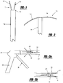
- the tissue fixation device includes a tissue tack of biocompatible material, the tack being generally shown by numeral 10 in the Figures.
- a barrel is a hollow lumen (in the deployment gun) in which the tissue tacks are placed prior to deployment into the body of a patient.
- tissue as used herein is meant to include, but is not limited to, an aggregation of morphologically similar cells and associated intercellular matter acting together to perform one or more specific functions in the body.
- tissue includes muscle, nerve, epidermal, and connective tissues.
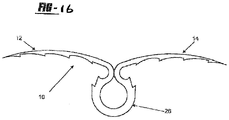
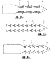
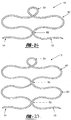
- the tissue tack 10 has a body portion 16 having at least two arms 12, 14 extending outwardly therefrom.
- the arms 12, 14 both include puncturing ends 18, 20 to allow for entry of the tissue tack 10 into the tissue.
- an anchoring member 26 Opposite the arms 12, 14 is an anchoring member 26, which extends from the body 16 of the device 10 in order to anchor the tack 10 when disposed in the tissue.
- the anchoring member which can be flush with the tissue when the tack10 is in tissue, prevents migration of the tack 10 into the tissue so that discomfort to the patient is minimized.
- the puncturing ends 18, 20 can be either an integral part of the tissue tack 10, or it can be a separate piece that is physically and/or chemically attached to the first end 16 of the tissue tack 10.
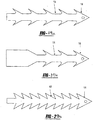
- the puncturing ends 18, 20 preferably include a pointed end portion 22 as in the embodiment of Figure 1 .
- the pointed end portion 22 can be in the shape of a fishhook.
- the fishhook can serve to prevent the tissue tack 10 from migrating backwards and allowing the tissue to become unattached.
- Any other suitable pointed end portion 22 can be used. Examples of such end portions 22 can include barbs, jagged edges or other tissue tack retaining devices.
- the end portions 22 can also be bevelled. Alternatively, the entire tissue tack 10 can include such barbs, jagged edges, or other retaining devices.
- the puncturing ends 18, 20 are made from the same biocompatible material as the tissue tack 10.
- the puncturing ends 18, 20 can be made of a different biocompatible material than the tissue tack 10 in order to enhance its puncturing capabilities.
- the puncturing ends 18, 20 can be manufactured separately than the tissue tack 10 if the puncturing ends 18, 20 are not an integral part of the tissue tack 10 using methods known to those of skill in the art.
- the anchoring member 26 is used to anchor the tissue tack 10 in the tissue and prevent migration. Without an anchoring member, the tissue tack 10 is otherwise free to migrate further into the tissue, both after initial deployment and also during the time that the tissue tack 10 remains in the patient's body. This can cause physical pain to the patient and can also cause damage to the tissue.
- the anchoring member 26 can be an integral part of the tissue tack 10, or it can be physically and/or chemically attached at the body portion 16 of the tissue tack 10.
- the anchoring member 26 is a loop, from which the arms 12, 14 extend.
- the anchoring member 26 can also be used as a retaining portion.
- the anchoring member 26 is integral with the arms 12, 14; however, it can be a separate piece chemically and/or physically attached to the arms 12, 14 via the body portion 16.
- the anchoring member 26 is used to keep the tissue tack 10 in position within a tissue tack deployer 30
- the anchoring member 26 is made from the same biocompatible material as the tissue tack 10.
- the anchoring member 26 can be made of different biocompatible materials relative to the tissue tack 10 in order to enhance anchoring and barrel-retaining capabilities.
- the anchoring member 26 can be manufactured separately from the tissue tack 10 if it is not an integral part of the tissue tack 10. The manufacturing can be accomplished using methods known to those of skill in the art.
- the tissue tack 10 can have modifications made to the exterior surface in order to enable the tissue tack to perform more effectively.
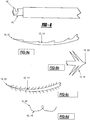
- the tissue tack arms 12, 14 can be modified to improve tissue fixation and the arm 12, 14 and anchoring member 26 can be modified to improve visibility by ultrasound and minimize ultrasound artefact and distortion of image.
- modifications include, but are not limited to, the addition of hooks, barbs, bristles and bends to the arms 12, 14 of the tissue tack 10 to improve tissue grasping and to increase the force required to remove the anchors (See Figures 9A to 9D ).
- the modifications can be made to improve tissue grasping capabilities and ease of removal.
- the tissue tack 10 is of a size relative to the incision in the tissue that is to be closed. Accordingly, the diameter of the arms and the total length of the tissue tack 10 can be selected to fit the incision, If the tissue tack 10 is being used to attach a periocardial patch in the heart, the size of the tissue tack 10 should be approximately 3 mm in diameter with an external length of 4 to 6 mm.
- the tissue tack 10 is made of biocompatible materials. Whenever a foreign object is placed inside the body, rejection reactions can occur ranging from mild to severe irritation and inflammation, and even death. To keep rejection minimal, implants must be biocompatible.
- the tissue tack 10 is made of stainless steel.
- Metals such as stainless steel, shape memory polymers, shape memory alloys, nitinol, titanium alloys, and cobalt alloys have high tensile, fatigue, and yield strengths, tow reactivity and good ductility. A closely packed crystal structure and metallic bonding make metals and alloys useful in internal fixation devices.
- polymers such as polyethylene (PE) and hydrogels can be used. Depending on the processing methods, polyethylene can be made flexible and elastic, or hard and smooth.
- Biodegradable polymers could be used in cases where an incision in the tissue is expected to heal and become functional again. These polymers can degrade by hydrolytic instability, hydration, molecular backbone cleavage, loss of molecular weight, and solubilization. The degradation byproducts are removable by the body itself by natural functions such as phagocytosis. Sutures of this type eliminate the need for a second operation to remove them. Biodegradable polymers can be natural or synthetic.
- Some natural polymers include collagen, which already comprises about 30% of the protein in the body, chitosan, which is derived from a polysaccharide called chitin found in crustacean exoskeletons, and polyhydroxyalkanoates (PHA), which are secreted by certain species of microorganisms.
- Synthetic polymers include poly(glycolic acid) (PGA), which has been used in absorbable sutures, poly(lactic acid) (PLA), copolymers of PGA and PLA, and polydioxananone (PDS). Ceramics and glasses can also be used for the tissue tack 10. Composites of materials can be used to optimize strength and flexibility in the tissue tack 10, and one or more of the materials can be degradable to allow for tissue integration.
- the tissue tack 10 can be laser cut from a band or cylinder of elastic material.
- the tissue tack 10 can also be formed using heat treatments or other methods known to those of skill in the art.
- tissue tack 10 can be coated in an immunosuppressible material or other coating that limits the ability of the tissue or body within which the tissue tack 10 is being placed.
- Biologicals or chemicals can be incorporated on the surface of the tissue tack 10 that can be released or directly interact with surrounding tissue to modify tissue reactivity and promote or inhibit cell and extracellular matrix adhesion.
- Examples of such material include, but are not limited to, immunosuppressive compounds and agents.
- Immunosuppressive agents are defined as agents that suppress immune responses.
- the agents can include, but are not limited to, immunoprotective cells, such as Sertoli cells, stem cells, stem cell by-products, or other compounds that create an immunosuppressive effect.
- immunosuppressive compounds include, but are not limited to, PKC inhibitors, glutamate receptor inhibitors, cyclosporins, FK506, corticosteroids, and ascomycins.
- the tissue tack 10 can include an imageable material so that the location of the tissue tack 10 in the patient's body can be determined by imaging methods such as ultrasound, magnetic resonance imaging (MRI), computed tomography (CT), X-ray, fluoroscopy, nuclear imaging or any other imaging method known in the art.
- imaging methods such as ultrasound, magnetic resonance imaging (MRI), computed tomography (CT), X-ray, fluoroscopy, nuclear imaging or any other imaging method known in the art.
- MRI magnetic resonance imaging
- CT computed tomography
- X-ray X-ray
- fluoroscopy nuclear imaging or any other imaging method known in the art.
- Radiopaque materials are commonly used such as stainless steel and nickel-titanium alloys. Radiopaque markers can also be used.
- polymers are typically used. Any other suitable imaging material can be used.
- the tissue tack 10 can be made of a combination of imageable materials and other biocompatible materials or via a cover 11 formed of an imageable material that is placed about the tissue tack 10. Methods of manufacturing the tissue tack 10 from the materials above are well known in the art.
- the tissue tack 10 can include physical modifications to better enable the tissue tack 10 to be visualized. This is accomplished by provide the best visualization of the arms 12,14 using ultrasound imaging at all incident angles, which is independent of the direction of the ultrasound beam. The modification also minimizes artifacts formed when the ultrasound beam strikes the arms 12,14.
- the modification can be accomplished via a diffusive surface modification or coating examples of which include, but are not limited to, wrapping a wire around the arms 12,14 or creating channels on the arms 12,14 to improve visualization.
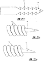
- Figure 5 shows a tissue tack 10 wherein the arms 12,14 are wrapped in copper wire 27 to improve visualization. The same effect can be achieved by cutting grooves, either linear or spiral, into the arms 12,14.
- the grooves can be cut using any mechanisms known to those of skill in the art
- the mechanisms can include, but are not limited to, lasers and etching.
- the tissue tack 10 can also include coils 13 made of nitinol, or other similar materials, to aid in the visibility of the tissue tack 10.
- the coils 13 should be coiled loosely enough to enhance the visibility of the tissue tack 10.
- the surface can also be made smoother via a coating including polyureihane foam or other similar compound (see Figure 17 ). Such a coating enables easier removal of the tissue tack 10, should removal become necessary.
- modifications can be combined depending on the needs or circumstances. For example, for some applications such as ASD patch fixation, visibility of the anchors with minimal distortion is desired. Whereas for mitral ring fixation, strength of tissue grasping is of greater importance due to the forces being applied on the ring and anchors.
- a combination of modifications can be used in different parts of the same anchor. For example, barbed arms 12,14 can be combined with a spiral wound wire or groove on the anchoring member 26. The design provides strength of tissue grasping while making the anchoring member 26 of the tissue tack 10 more visible for navigating instruments to the tissue tack 10 or determining how many tissue tacks 10 have been deployed and in what location.
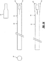
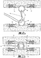
- a tissue tack deployer 30 is provided as shown generally in Figure 2 .
- the deployer 30 includes a housing 32 having a hollow barrel 34 connected thereto and a handle 36.
- the barrel 34 includes a spring loaded trigger 38 and a locking mechanism 40 on an end 41 of the barrel 34.
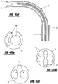
- the barrel 34 can include a curved extension 35, as shown in Figure 12 .
- the curved extension 35 can be preset or can be steered depending upon the materials used.
- the curved extension 35 is preset such that upon extending the curved extension 35 from the barrel 34 the curved extension 35 curves pursuant to the preset limitations.
- the curved extension 35 can include a curving mechanism for altering the degree of curvature, using steering mechanisms known to those of skill in the art.
- the locking mechanism 40 maintains the tissue tacks 10 that are mounted in the barrel 34 and allows the tissue tacks 10 to travel along the barrel 34.
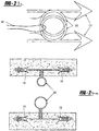
- the locking mechanism 40 has a tip 42, as shown in Figures 4 , 11 , 14 and 15 , for both holding the tissue tack 10 in place and releasing the tissue tack 10 when in the desired location.
- the tip 42 can have a hook, gripper, key lock, or other similar design.
- the tip 42 can be formed from as few as one part or multiple parts 43,45 (as shown in Figures 14 and 15 ). When multiple parts 43,45 are utilized, the parts 43,45 converge to maintain the tissue tack 10 within an opening 47 in the parts 43,45.
- the parts 43,45 are maintained in a closed position by the barrel 34 of the deployer 30, therefore when the tip 42 is extended from the barrel 34, the parts 43,45 are no longer held together and the tissue tack 10 can be released.
- the tip 34 can include a mechanism for locking/closing the parts of the tip 42, which can be released upon deployment of the tissue tack 10.
- Figure 11 shows a guide 52 located on the end of the tip 34.
- the guide 52 includes a male portion 54 that mates with a female guide portion 56 present on a patch previously deployed, such that the male portion 54 can align with the female portion 56 to ensure that the tissue tack 10 is deployed in the appropriate position.
- the deployer guide 52 functions as a key that must fit into a keyhole prior to deployment of the tissue tack 10.
- the system enables the surgeon to confirm that the appropriate number of tissue tacks 10 have been deployed and that the tissue tacks 10 have been deployed in the appropriate locations, without having to rely on additional imaging devices.
- the system also prevents a tissue tack 10 from being deployed too close to an edge of the patch that the tissue tack 10 is affixing.
- the tip 42 is designed to maintain the tissue tack 10 in place prior to deployment Further, the tip 42 can be used to removing the tissue tack 10 by grasping, snaring, or hooking the tissue tack 10 and thereby removing the tissue tack 10.
- the deployer 30 can include lumens 58 that enable insertion of additional instruments for use at the site of deployer 30 insertion.
- the lumen 58 enable the insertion of a light, vacuum, optics, a patch deployment device, or other devices that can be used in conjunction with the deployer 30 used in the combination of the present invention.
- any device that can be used during a laparoscopic or endoscopic procedure can be used with the deployer 30.
- the device can also utilize real-time 3D echocardiography (RT3DE) via the above lumen 58.
- RT3DE real-time 3D echocardiography
- the deployer 30 includes a spring loaded trigger 36 which can actuate the motion of the tissue tack 10 and can be pulled by the finger of an operator. Inside the housing 32, the trigger 36 is connected to a spring-loaded drive mechanism that pushes the tissue tack 10 out of the barrel 34 causing the device 10 to be deployed into the tissue of the patient. A handle can also be attached to the housing 32 to ease in the operation and handling of the deployer 30.
- the deployer 30 can include a pressure trigger that is able to actuate the motion of the tissue tack 10.
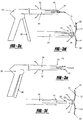
- a trigger may include a handle having two arms formed into a V-shape such that the bottom of the V is distal to the barrel and the two arms of the handle support the pressure trigger therebetween.
- the bottom of the V may contain a hinge that connects the two arms.
- the trigger may include a pressure gauge that can be actuated by moving the two arms of the handle together. The closer the two arms are brought to one another, the higher the pressure.
- the pressure gauge may be matingly attached to the barrel via a female nut which engages and maintains the barrel in place.
- the pressure gauge can be actuated to a predetermined pressure, thereby ensuring that enough pressure is used to deploy the tissue tack.
- the pressure gauge can also include a release valve that enables pressure to be released from the deployer if too much pressure is present.
- a mounting member in the barrel 34 can aid in mounting the tissue tacks 10.
- a mounting member can include a guide mechanism which guides the tissue tacks 10 mounted in the barrel 34.
- Such a guide mechanism can allow the tissue tack 10 to move both linearly along the barrel 34 and in a spiraling manner simultaneously during entry into the tissue.
- the guide mechanism can include an open end and a slot that runs along a length of the barrel 34 in order to accommodate the arms 12,14 of the tissue tack 10.
- the tissue tacks 10 can be seated on to the barrel 34 in a manner known to those skilled in the art, or in any other suitable manner.
- the tissue tack 10 used in the combination of the present invention is preferably used to interconnect a patient's tissue together.
- the tissue can be heart tissue, muscle tissue, or vascular tissue.
- the tissue tacks 10 shown in Figures 27 to 29 have a modified anchoring member 26, such that it is twisted to create at least one tissue separating device 60 with at least one tissue separation spaces 62 that enables a single tissue tack 10 to be used to affix multiple layers of tissue.
- the twisting of the anchoring member 26 creates a small generally circular anchoring member 26 and a larger, generally oval-shaped, tissue separating device 60, as shown in Figures 27 to 29 . Therefore, when the tissue tack 10 is deployed into layers of tissue, the tissue separating device 60 maintains a distance between layers by keeping the layers of tissue in tissue separation spaces 62. Multiple tissue separation devices 60 can be included in a single tissue tack 10.
- the tissue that is being connected can be two opposing sides of an incision. It can also be a native piece of tissue and a graft or prosthesis to be attached to that native piece of tissue.
- closures include, but are not limited to, the fixation of a patch to tissue for closure of atrial septal defect, ventricular septal defect, orifice or opening into a vessel or aneurysm (out pouching) in the heart or blood vessel, fixation of two tissue layers together such as two edges of a blood vessel or valve leaflet, vessel to vessel anastomosis, vessel to synthetic tube graft anastomosis, and approximation of tissue under tension by a process of interlocking two tissue tacks 10 that are attached to separate tissue layers.
- tissue tack 10 can be used to comply and fix to a predetermined position next to another system or catheter, for cutting, suturing, monitorization of pressure, thermal, electrocardiographical, or of electrophisiological ablation or the device can have in its distal end one or more sensorial and transmissioner ends: thermal, magnetics, echographics, radio frequency, radar and others, that allows determining its location in a tridimensional field, echographic, radiologic, magnetic, of radio frequency, thermal or by radar.
- the tissue tack can also be used to close cardiac atrial appendix by anchors, to close PFO, to close ASD, to close VSD, to reduce the mitral ring, to fix two valves of a cardiac valve through its distal end, to close any orifice by means of anchors with or without an additional weave, to fix the aneurism of a VSD by means of an anchor to close the same one, to introduce one patch through the aorta pulling back and to introduce the system of anchors by the end of the heart, to fix patch from the right ventricle.
- the present disclosure provides a method, not forming part of the invention, of suturing the tissue with the tissue tack 10 by puncturing the tissue of a patient to allow entry of the tissue tack 10 into the tissue.
- the tissue tack 10 is flushly anchored in the tissue so that the tissue is effectively held together.
- the method, not forming part of the invention can also include, prior to the puncturing step, a step of deploying the tissue tack 10 through an incision in the tissue in order to suture the tissue.
- the deploying step is accomplished by inserting a tissue tack deployer 30 into an incision, and then guiding the deployer 30 to the site in need of suturing.
- the deployer 30 can also be inserted into a trocar that is disposed through the incision.
- a trocar can be used in such operations as a cardiovascular operation.
- the deployer 30 can be guided to the suture site by using an imaging method, not forming part of the invention, such as ultrasound, MRI, CT, X-ray, fluoroscopy, or nuclear imaging.
- the arms 12,14 of the tissue tack 10 Prior to entry into the tissue, the arms 12,14 of the tissue tack 10 are straightened and forced together, in parallel, within a deployment device.
- the tissue tack 10 enters the tissue and the arms 12,14 open and extend in opposite directions, as shown in Figure 2 .
- the anchoring member 26 can be folded to limit the size of the tissue tack 10 prior to deployment. The folding is similar to what occurs with the arms 12,14, wherein the anchoring member 26 is deformed into a straightened position to limit the size of the tissue tack 10 within the deployer 30.
- the deployer 30 is used to insert the tissue tacks 10 into the patient's tissue.
- the tissue tack deployer 30 is in the shape of a gun. Any other suitable shape can also be used.
- the deployer 30 is of a small size. It can be produced by any method known to those of skill in the art for forming a deployer 30 as disclosed above.
- the entire deployer 30 or individual parts can be made of any suitable materials such as metals, plastics, ceramics, and composites.
- the deployer 30 can be used during macrosurgery and microsurgery procedures.
- a computer can be used to control the deployer 30.
- a robot can be used to move and manipulate the deployer 30.
- the housing 32 is the base for the deployer 28 upon which other elements are connected.
- a hollow barrel 34 is operatively connected to the housing 32.
- the tissue tacks 10 rest in the barrel 34 prior to deployment into tissue.
- the diameter of the barrel 34 is such that it can accommodate the diameter of tissue tack 10 required for the suture.
- the length of the barrel 34 is such that it can accommodate the length of the tissue tack 10 required for the suture.
- the length of the barrel 34 can also be extended so that a plurality of tissue tacks 10 can be loaded within the deployer 28.
- the barrel 34 should be able to fit though a trocar and cannula if they are used in the operating procedure.
- a method, not forming part of the invention, of deploying a tissue tack 10 into tissue is disclosed. This is accomplished by loading a device 10 onto the barrel 34 of the deployer 30, inserting the barrel 34 through an incision of the patient and into the tissue, guiding an end of the barrel 34 to the site to be sutured, and finally driving the device 10 off of the barrel 34 and into the tissue at the suture site.
- a plurality of tissue tacks 10 can be loaded. The tissue tack 10 is loaded so that the tissue tack 10 sits inside the barrel 34, and the arms 12,14 of the tissue tack 10 projects outside of the barrel 34.
- the barrel 34 can be inserted in a trocar disposed in the incision of a patient.
- the end of the barrel 34 can be imaged while it is in the tissue in order to guide the barrel 34 to the suture site. This can be accomplished by an imaging method, not forming part of the invention, such as ultrasound, MRI, CT, X-ray, fluoroscopy, or nuclear imaging. Any other suitable imaging method, not forming part of the invention, known to those of skill in the art can also be used.
- the tissue tack 10 can be driven off of the barrel 34 by any other suitable method, not forming part of the invention.
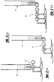
- the deployer When inserting multiple tissue tacks 10, the deployer functions by placing the first tissue tack 10 in place. Then, a second tissue tack 10 can be threaded through the first tissue tack 10 and is then deployed on an opposite side of the tissue. Once the second tissue tack 10 is released, the two edges of the tissue pull together. The process is repeated with numerous tissue tacks 10 until the edges of the tissue are pulled together (see Figure 25 ).
- two or more tissue tacks 10 can be placed on opposite sides of damaged tissue. Subsequent to deployment, surgical thread, sutures, staples, bands, and other similar devices, can be woven or threaded through the tissue tacks 10. The one can pull the tissue tacks 10 into close proximity, thereby fixing the damaged tissue. Once the damage has been repaired, a knot, collar, crimp, or other similar device capable of preventing the thread from coming undone is affixed on the end of the thread. Alternatively, the ends of the thread can be affixed to one another, such as for example via heating, bonding, or magnetically adhering the ends to one another.
- tissue tacks 10 can be interconnected.
- the interconnection is achieved by inserting the anchoring mechanism 26 of a first tissue tack 10 into the anchoring mechanism 26 of a second tissue tack 10'. Since, the anchoring mechanism 26 is made of a pliable material, the interconnection is easy to achieve.
- the anchoring mechanism 26 of the first tissue tack is larger than the anchoring mechanism 26 of the second tissue tack 10', thereby preventing the first tissue tack 10 from backing out of the interconnection.
- the present disclosure is beneficial because the surgeon can perform the therapy in a beating heart and the surgeon can see how the therapy affects the patient in an objective way.
- the surgeon can select the kind and size of weave depending where the tissue tack going to work, the surgeon can see the weave in all the layers, and also where the sutures arrive (the present surgeon can only see the surfaces). Also, verification can occur to see if the therapy/treatment is working on the heart conduction system. The surgeon is also able to plan and modify the therapy/treatment with opportune information in real time.
- a further advantage of the present disclosure is that the puncturing ends 18,20 can be used as a temporal or definitive pacemaker, thanks to the form of the tissue tack 10, and its manner of implantation. Since the implantation of the anchor is atraumatic, this allows an optimal bioelectric contact, where myocardial cell is not affected with an excellent contact, producing a good myocardic answer by an effective energy transmission. The battery life is thereby extended in a significant way. In other words, the patient receives a fully compatible electrophysiological system, with a better physiological answer and greater battery life.
- the currently available separator that allows the surgeon a good vision of the operating field is replaced by the three-dimensional images in real time.
- the surgical forceps are replaced by a vacuum system that allows the surgeon to stabilize and move the different weaves.
- the thread, needles, and carry needles forceps are replaced by tissue tacks 10 allowing the realization of continuous suture.
- the advantage of this system is not only its size and versatility, it also allows removal of them, so they can float in the site of administration until deployment or the tissue tack 10 can be removed if necessary.
Landscapes
- Health & Medical Sciences (AREA)
- Surgery (AREA)
- Life Sciences & Earth Sciences (AREA)
- Medical Informatics (AREA)
- Nuclear Medicine, Radiotherapy & Molecular Imaging (AREA)
- Engineering & Computer Science (AREA)
- Biomedical Technology (AREA)
- Heart & Thoracic Surgery (AREA)
- Molecular Biology (AREA)
- Animal Behavior & Ethology (AREA)
- General Health & Medical Sciences (AREA)
- Public Health (AREA)
- Veterinary Medicine (AREA)
- Rheumatology (AREA)
- Surgical Instruments (AREA)
- Prostheses (AREA)
Claims (15)
- Eine Kombination aus mindestens einer Gewebefixierungsklammer (10) aus biokompatiblem Material zur Verwendung beim Verschließen von Inzisionen in Gewebe bei einem kardiochirurgischen Eingriff, wie etwa einem Anastomoseeingriff, und einer Einsatzpistole (30), in die die mindestens eine Klammer (10) geladen und von der aus diese eingesetzt werden kann, wobei jede Klammer (10) einen Körperabschnitt (16) beinhaltet, der eine Schlaufe an einem Ende von diesem und mindestens zwei flexible Arme (12, 14) an einem anderen Ende von diesem aufweist, wobei die Arme (12, 14) angeordnet sind, um in der Einsatzpistole (30) parallel aneinandergepresst zu werden, wobei die Schlaufe als Ankerglied (26) zum Verankern der Klammer (10) in Gewebe und zum Verhindern der Migration von dieser wirkt, und bei dem die Arme (12, 14) Enden (18, 20) zum Punktieren und Eintreten in das Gewebe während des Eingriffs aufweisen, wobei die Arme (12, 14) ferner angeordnet sind, um sich in entgegengesetzte Richtungen von dem Ankerglied (26) weg nach außen zu erstrecken, wenn sie bei dem Eingriff in dem Gewebe eingesetzt werden; dadurch gekennzeichnet, dass
die Einsatzpistole (30) ein Gehäuse (32) beinhaltet, das einen hohlen Lauf (34), der mit diesem verbunden ist, und einen Verriegelungsmechanismus (40) an einem Ende (41) des hohlen Laufs (34) aufweist, wobei der Verriegelungsmechanismus (40) eine Spitze (42) sowohl zum Halten der mindestens einen Klammer (10) an ihrem Platz als auch zum Lösen der mindestens einen Klammer (10), wenn sie an der gewünschten Stelle ist, aufweist. - Eine Kombination gemäß Anspruch 1, wobei das biokompatible Material Edelstahl, ein Formgedächtnispolymer, eine Formgedächtnislegierung, eine Titanlegierung oder eine Kobaltlegierung ist.
- Eine Kombination gemäß Anspruch 1 oder Anspruch 2, wobei die Arme (12, 14) Sicherungsmittel, wie etwa Widerhaken oder gezackte Ränder, zum Sichern der Klammer (10) an ihrem Platz in dem Gewebe aufweisen.
- Eine Kombination gemäß einem der vorhergehenden Ansprüche, wobei das Ankerglied (26) aus einem biegsamen Material gefertigt ist.
- Eine Kombination gemäß einem der vorhergehenden Ansprüche, wobei die Arme (12, 14) jeweils eine Beschichtung aufweisen, wobei die Beschichtung eine immunsuppressive Beschichtung oder eine Polyurethanfilmbeschichtung ist.
- Eine Kombination gemäß Anspruch 5, wobei die immunsuppressive Beschichtung aus einem PKC-Hemmer, Glutamat-Rezeptor-Hemmer, Cyclosporin, FK506, Corticosteroid oder Ascomycin ist.
- Eine Kombination gemäß einem der vorhergehenden Ansprüche, wobei das Ankerglied (26), der Körperabschnitt (16) und die Arme (12, 14) einstückig ausgebildet sind.
- Eine Kombination gemäß einem der vorhergehenden Ansprüche, die ferner ein Gewebetrennmittel (60) zum Trennen von Schichten von Gewebe, in das die Gewebefixierungsklammer (10) eingesetzt wird, umfasst.
- Eine Kombination gemäß einem der Ansprüche 1 bis 7, die eine Vielzahl von Klammern (10) umfasst, bei der das Ankerglied (26) auf jeder Klammer (10) angepasst ist, um mit dem Ankerglied (26) auf einer anderen der Klammern (10) verbunden zu werden.
- Eine Kombination gemäß einem der vorhergehenden Ansprüche, bei der das Gehäuse (32) der Einsatzpistole (30) ferner einen Griff (32) und einen federbelasteten Auslöser (36) umfasst.
- Eine Kombination gemäß einem der vorhergehenden Ansprüche, wobei die Spitze (42) des Verriegelungsmechanismus (40) eine Haken-, Greifer- oder Schlüsselschlossform aufweist.
- Eine Kombination gemäß Anspruch 10 oder 11, die ferner mindestens ein Lumen (58) innerhalb des Laufs (34) zum Ermöglichen der Einführung von mindestens einem zusätzlichen Instrument, wie etwa einem Echtzeit-3D-Echokardiografiegerät, einem Laser, einer Lichtquelle oder einem Vakuuminstrument, umfasst.
- Eine Kombination gemäß einem der vorhergehenden Ansprüche, die ferner ein Befestigungsglied (44) in dem Lauf (34) umfasst, wobei das Befestigungsglied (44) einen Führungsmechanismus (46) umfasst, der der mindestens einen Klammer (10) erlaubt, sich sowohl linear entlang des Laufs (34) als auch gleichzeitig in einer spiralartigen Weise während des Eintretens in das Gewebe zu bewegen.
- Eine Kombination gemäß Anspruch 13, wobei der Führungsmechanismus (46) ein offenes Ende (48) und einen Schlitz (50) umfasst, der über die Länge des Laufs (34) verläuft, um die Arme (12, 14) der Klammer (10) unterzubringen.
- Eine Kombination gemäß einem der vorhergehenden Ansprüche, die ferner eine Führung (52) umfasst, die sich an dem Ende der Spitze (34) befindet, wobei die Führung (52) einen Steckabschnitt (54) aufweist, der mit einem Aufnahmeführungsabschnitt (56) zusammenpasst, der auf einem zuvor eingesetzten Patch vorliegt.
Applications Claiming Priority (4)
| Application Number | Priority Date | Filing Date | Title |
|---|---|---|---|
| US76326006P | 2006-01-30 | 2006-01-30 | |
| US78103406P | 2006-03-10 | 2006-03-10 | |
| US74618806P | 2006-05-02 | 2006-05-02 | |
| PCT/US2007/002644 WO2007089843A2 (en) | 2006-01-30 | 2007-01-30 | Tissue tack |
Publications (4)
| Publication Number | Publication Date |
|---|---|
| EP1986554A2 EP1986554A2 (de) | 2008-11-05 |
| EP1986554A4 EP1986554A4 (de) | 2012-01-04 |
| EP1986554B1 true EP1986554B1 (de) | 2020-09-30 |
| EP1986554B8 EP1986554B8 (de) | 2020-11-18 |
Family
ID=38328027
Family Applications (1)
| Application Number | Title | Priority Date | Filing Date |
|---|---|---|---|
| EP07762739.6A Active EP1986554B8 (de) | 2006-01-30 | 2007-01-30 | Gewebeklammer |
Country Status (3)
| Country | Link |
|---|---|
| US (1) | US8491631B2 (de) |
| EP (1) | EP1986554B8 (de) |
| WO (1) | WO2007089843A2 (de) |
Families Citing this family (43)
| Publication number | Priority date | Publication date | Assignee | Title |
|---|---|---|---|---|
| EP1871306A4 (de) | 2005-04-01 | 2012-03-21 | Univ Colorado | Transplantat-fixiervorrichtung und-verfahren |
| US9456811B2 (en) | 2005-08-24 | 2016-10-04 | Abbott Vascular Inc. | Vascular closure methods and apparatuses |
| US8979872B2 (en) * | 2007-03-13 | 2015-03-17 | Longevity Surgical, Inc. | Devices for engaging, approximating and fastening tissue |
| WO2009097463A1 (en) * | 2008-01-29 | 2009-08-06 | Superdimension, Ltd. | Target identification tool for intra body localization |
| US9358002B2 (en) * | 2008-04-01 | 2016-06-07 | Covidien Lp | Anchoring device |
| US9034011B2 (en) * | 2008-04-01 | 2015-05-19 | Covidien Lp | Anchoring device |
| US10376261B2 (en) * | 2008-04-01 | 2019-08-13 | Covidien Lp | Anchoring suture |
| US8430933B2 (en) | 2008-07-24 | 2013-04-30 | MedShape Inc. | Method and apparatus for deploying a shape memory polymer |
| US8069858B2 (en) | 2008-07-24 | 2011-12-06 | Medshape Solutions, Inc. | Method and apparatus for deploying a shape memory polymer |
| AU2009282596A1 (en) | 2008-08-19 | 2010-02-25 | Wilson-Cook Medical Inc. | Apparatus for removing lymph nodes or anchoring into tissue during a translumenal procedure |
| JP2012511403A (ja) * | 2008-12-09 | 2012-05-24 | クック メディカル テクノロジーズ エルエルシー | 鋲留め器具の制御放出のための装置と方法 |
| EP2373230B1 (de) * | 2008-12-09 | 2012-11-28 | Cook Medical Technologies LLC | Zurückziehbare heftvorrichtung |
| JP2012512715A (ja) * | 2008-12-19 | 2012-06-07 | クック メディカル テクノロジーズ エルエルシー | 厚さが変化する鋲留め器具、並びにその送達及び配備の方法 |
| US8388349B2 (en) * | 2009-01-14 | 2013-03-05 | Ams Research Corporation | Anastomosis deployment force training tool |
| US8734484B2 (en) | 2009-04-21 | 2014-05-27 | Medtronic, Inc. | System and method for closure of an internal opening in tissue, such as a trans-apical access opening |
| AU2010254151B2 (en) | 2009-05-28 | 2013-11-28 | Cook Medical Technologies Llc | Tacking device and methods of deployment |
| DE102010000320A1 (de) * | 2010-02-05 | 2011-08-11 | Aesculap AG, 78532 | Medizinische Fixiereinrichtung |
| US9314314B2 (en) * | 2011-02-15 | 2016-04-19 | Rotation Medical, Inc. | Anatomical location markers and methods of use in positioning sheet-like materials during surgery |
| US9427493B2 (en) | 2011-03-07 | 2016-08-30 | The Regents Of The University Of Colorado | Shape memory polymer intraocular lenses |
| US9149276B2 (en) * | 2011-03-21 | 2015-10-06 | Abbott Cardiovascular Systems, Inc. | Clip and deployment apparatus for tissue closure |
| US9414822B2 (en) | 2011-05-19 | 2016-08-16 | Abbott Cardiovascular Systems, Inc. | Tissue eversion apparatus and tissue closure device and methods for use thereof |
| US9474515B2 (en) * | 2011-09-14 | 2016-10-25 | Boston Scientific Scimed, Inc. | Endoscopic hemostasis closure device and delivery system |
| WO2013123388A1 (en) * | 2012-02-15 | 2013-08-22 | Children's Hospital- Boston | Right ventricular papillary approximation |
| US11547396B2 (en) | 2012-08-10 | 2023-01-10 | W. L. Gore & Associates, Inc. | Devices and methods for securing medical devices within an anatomy |
| US11458007B2 (en) | 2012-08-10 | 2022-10-04 | W. L. Gore & Associates, Inc. | Devices and methods for limiting a depth of penetration for an anchor within an anatomy |
| EP2887885B1 (de) * | 2012-08-22 | 2018-02-28 | Covidien LP | Vorrichtung für gewebefixierung |
| US9855034B2 (en) * | 2012-08-23 | 2018-01-02 | Covidien Lp | Tissue fixation device |
| US20160074640A1 (en) * | 2012-10-05 | 2016-03-17 | Miguel A. Linares | Attachable uterine device with integrated and time release medicinal administering component and insertion tool for implanting such a device |
| US10925606B2 (en) * | 2012-10-15 | 2021-02-23 | Guy Friedman | Tendon repair apparatus |
| WO2016025019A1 (en) * | 2014-08-11 | 2016-02-18 | Yeung Jeffrey E | Tissue fastener in a needle |
| US20160367120A1 (en) | 2015-06-19 | 2016-12-22 | Children's Medical Center Corporation | Optically Guided Surgical Devices |
| WO2017112856A1 (en) * | 2015-12-22 | 2017-06-29 | Prodeon, Inc. | System and method for increasing a cross-sectional area of a body lumen |
| CA3014320A1 (en) | 2016-02-12 | 2017-08-17 | Children's Medical Center Corporation | Instrument port with integrated imaging system |
| US10426457B2 (en) | 2017-02-07 | 2019-10-01 | Apollo Endosurgery Us, Inc. | Surgical fastener deployment system |
| US11458004B2 (en) | 2017-10-19 | 2022-10-04 | C.R. Bard, Inc. | Self-gripping hernia prosthesis |
| US11284788B2 (en) | 2018-03-09 | 2022-03-29 | The Children's Medical Center Corporation | Instrument port with fluid flush system |
| US11547276B2 (en) | 2018-03-09 | 2023-01-10 | The Children's Medical Center Corporation | Optical bulb for surgical instrument port |
| US11324555B2 (en) | 2018-03-09 | 2022-05-10 | The Children's Medical Center Corporation | Instrument port including optical bulb secured to port body |
| US11213316B2 (en) | 2018-03-09 | 2022-01-04 | The Children's Medical Center Corporation | Gasket with multi-leaflet valve for surgical port apparatus |
| US20210275162A1 (en) * | 2020-03-05 | 2021-09-09 | Apollo Endosurgery Us, Inc. | Surgical fastener deployment system |
| AU2021336420A1 (en) * | 2020-09-02 | 2023-03-23 | Vesteck, Inc. | Remote surgical suture system |
| US12349893B2 (en) | 2021-02-25 | 2025-07-08 | Cook Medical Technologies Llc | Implantable tissue anchors, kits that include a tissue anchor, and related methods of treatment |
| US20230233201A1 (en) * | 2022-01-24 | 2023-07-27 | Covidien Lp | Apparatus and method for endoscopically closing gastrointestinal defects |
Family Cites Families (19)
| Publication number | Priority date | Publication date | Assignee | Title |
|---|---|---|---|---|
| US1241054A (en) * | 1916-07-22 | 1917-09-25 | Owen E Hulehan | Wire staple. |
| US4887601A (en) * | 1987-11-06 | 1989-12-19 | Ophthalmic Ventures Limited Partnership | Adjustable surgical staple and method of using the same |
| US5263973A (en) * | 1991-08-30 | 1993-11-23 | Cook Melvin S | Surgical stapling method |
| US5289963A (en) * | 1991-10-18 | 1994-03-01 | United States Surgical Corporation | Apparatus and method for applying surgical staples to attach an object to body tissue |
| US5242457A (en) * | 1992-05-08 | 1993-09-07 | Ethicon, Inc. | Surgical instrument and staples for applying purse string sutures |
| US5632717A (en) * | 1994-10-07 | 1997-05-27 | Yoon; Inbae | Penetrating endoscope |
| US20050004576A1 (en) * | 1998-11-23 | 2005-01-06 | Benderev Theodore V. | System for securing sutures, grafts and soft tissue to bone and periosteum |
| US6200330B1 (en) * | 1998-11-23 | 2001-03-13 | Theodore V. Benderev | Systems for securing sutures, grafts and soft tissue to bone and periosteum |
| WO2000040159A1 (en) * | 1998-12-31 | 2000-07-13 | Yeung Teresa T | Tissue fastening devices and delivery means |
| US6231561B1 (en) * | 1999-09-20 | 2001-05-15 | Appriva Medical, Inc. | Method and apparatus for closing a body lumen |
| GB2359024A (en) * | 2000-02-09 | 2001-08-15 | Anson Medical Ltd | Fixator for arteries |
| US6776784B2 (en) * | 2001-09-06 | 2004-08-17 | Core Medical, Inc. | Clip apparatus for closing septal defects and methods of use |
| US7108701B2 (en) * | 2001-09-28 | 2006-09-19 | Ethicon, Inc. | Drug releasing anastomosis devices and methods for treating anastomotic sites |
| WO2003053289A1 (en) * | 2001-12-21 | 2003-07-03 | Simcha Milo | Implantation system for annuloplasty rings |
| US7150750B2 (en) * | 2002-01-10 | 2006-12-19 | Boston Scientific Scimed, Inc. | Method and device for endoscopic suturing |
| EP1478283B1 (de) * | 2002-02-25 | 2010-07-14 | Jeffrey E. Yeung | Spreizbares befestigungselement mit zusammendrückbaren greifelementen |
| US8287555B2 (en) * | 2003-02-06 | 2012-10-16 | Guided Delivery Systems, Inc. | Devices and methods for heart valve repair |
| WO2004112652A2 (en) | 2003-06-20 | 2004-12-29 | Medtronic Vascular, Inc. | Device, system, and method for contracting tissue in a mammalian body |
| US7556647B2 (en) * | 2003-10-08 | 2009-07-07 | Arbor Surgical Technologies, Inc. | Attachment device and methods of using the same |
-
2007
- 2007-01-03 US US12/162,633 patent/US8491631B2/en active Active
- 2007-01-30 WO PCT/US2007/002644 patent/WO2007089843A2/en not_active Ceased
- 2007-01-30 EP EP07762739.6A patent/EP1986554B8/de active Active
Non-Patent Citations (1)
| Title |
|---|
| None * |
Also Published As
| Publication number | Publication date |
|---|---|
| EP1986554B8 (de) | 2020-11-18 |
| EP1986554A4 (de) | 2012-01-04 |
| WO2007089843A2 (en) | 2007-08-09 |
| WO2007089843A3 (en) | 2008-02-07 |
| US8491631B2 (en) | 2013-07-23 |
| EP1986554A2 (de) | 2008-11-05 |
| US20090306681A1 (en) | 2009-12-10 |
Similar Documents
| Publication | Publication Date | Title |
|---|---|---|
| EP1986554B1 (de) | Gewebeklammer | |
| US11931023B2 (en) | Tissue clip | |
| US10568740B2 (en) | Device and method to plicate the tricuspid valve | |
| JP5724134B2 (ja) | 後退可能な鋲留め器具 | |
| US20220142640A1 (en) | Length of self-retaining suture and method and device for using the same | |
| US20090054975A1 (en) | Deployment device for cardiac surgery | |
| US10575851B2 (en) | Atrial appendage ligation | |
| US20020173803A1 (en) | Self-closing surgical clip for tissue | |
| US20110301620A1 (en) | Device for suturing two hollow biological tissues | |
| JP2001507972A (ja) | 侵襲を最小にした血管および内視鏡外科手術のための環状鉤付きループ外科手術用ファスナー、器具、およびその方法 | |
| US20170156861A1 (en) | Percutaneous or Minimally Invasive Cardiac Valve Repair System and Methods of Using the Same | |
| US20110238090A1 (en) | Methods and devices for delivering sutures in tissue | |
| JP2001507976A (ja) | 最小侵襲性脈管および内視鏡検査外科手術のための、縫合式ステープル外科手術用固定器具、機器、およびその方法 | |
| JPH11514269A (ja) | 動脈閉塞にバイパスを形成するためのおよび/またはその他の経血管的手法を実施するための方法および装置 | |
| JP2018515221A (ja) | 吻合を形成するためのシステム、デバイス、および方法 | |
| US20100069924A1 (en) | Methods for achieving serosa-to-serosa closure of a bodily opening using one or more tacking devices | |
| US20100145362A1 (en) | Apparatus and methods for controlled release of tacking devices | |
| US9486230B2 (en) | Percutaneous aneurysm inversion and ligation |
Legal Events
| Date | Code | Title | Description |
|---|---|---|---|
| PUAI | Public reference made under article 153(3) epc to a published international application that has entered the european phase |
Free format text: ORIGINAL CODE: 0009012 |
|
| 17P | Request for examination filed |
Effective date: 20080829 |
|
| AK | Designated contracting states |
Kind code of ref document: A2 Designated state(s): AT BE BG CH CY CZ DE DK EE ES FI FR GB GR HU IE IS IT LI LT LU LV MC NL PL PT RO SE SI SK TR |
|
| DAX | Request for extension of the european patent (deleted) | ||
| A4 | Supplementary search report drawn up and despatched |
Effective date: 20111202 |
|
| RIC1 | Information provided on ipc code assigned before grant |
Ipc: A61B 17/068 20060101ALI20111128BHEP Ipc: A61B 17/064 20060101ALI20111128BHEP Ipc: A61B 17/04 20060101ALI20111128BHEP Ipc: A61B 17/08 20060101AFI20111128BHEP |
|
| 17Q | First examination report despatched |
Effective date: 20131009 |
|
| RAP1 | Party data changed (applicant data changed or rights of an application transferred) |
Owner name: CHILDREN'S MEDICAL CENTER CORPORATION |
|
| STAA | Information on the status of an ep patent application or granted ep patent |
Free format text: STATUS: EXAMINATION IS IN PROGRESS |
|
| GRAP | Despatch of communication of intention to grant a patent |
Free format text: ORIGINAL CODE: EPIDOSNIGR1 |
|
| STAA | Information on the status of an ep patent application or granted ep patent |
Free format text: STATUS: GRANT OF PATENT IS INTENDED |
|
| INTG | Intention to grant announced |
Effective date: 20190730 |
|
| GRAS | Grant fee paid |
Free format text: ORIGINAL CODE: EPIDOSNIGR3 |
|
| RAP1 | Party data changed (applicant data changed or rights of an application transferred) |
Owner name: CHILDREN'S MEDICAL CENTER CORPORATION Owner name: DUPONT, PIERRE |
|
| GRAA | (expected) grant |
Free format text: ORIGINAL CODE: 0009210 |
|
| STAA | Information on the status of an ep patent application or granted ep patent |
Free format text: STATUS: THE PATENT HAS BEEN GRANTED |
|
| AK | Designated contracting states |
Kind code of ref document: B1 Designated state(s): AT BE BG CH CY CZ DE DK EE ES FI FR GB GR HU IE IS IT LI LT LU LV MC NL PL PT RO SE SI SK TR |
|
| REG | Reference to a national code |
Ref country code: GB Ref legal event code: FG4D Ref country code: CH Ref legal event code: EP |
|
| REG | Reference to a national code |
Ref country code: AT Ref legal event code: REF Ref document number: 1317940 Country of ref document: AT Kind code of ref document: T Effective date: 20201015 |
|
| REG | Reference to a national code |
Ref country code: DE Ref legal event code: R081 Ref document number: 602007060674 Country of ref document: DE Owner name: TRUSTEES OF BOSTON UNIVERSITY, BOSTON, US Free format text: FORMER OWNERS: CHILDREN'S MEDICAL CENTER CORPORATION, BOSTON, MASS., US; DUPONT, PIERRE, BOSTON, MA, US Ref country code: DE Ref legal event code: R081 Ref document number: 602007060674 Country of ref document: DE Owner name: CHILDREN'S MEDICAL CENTER CORPORATION, BOSTON, US Free format text: FORMER OWNERS: CHILDREN'S MEDICAL CENTER CORPORATION, BOSTON, MASS., US; DUPONT, PIERRE, BOSTON, MA, US Ref country code: DE Ref legal event code: R082 Ref document number: 602007060674 Country of ref document: DE Representative=s name: MURGITROYD & COMPANY, DE |
|
| REG | Reference to a national code |
Ref country code: DE Ref legal event code: R096 Ref document number: 602007060674 Country of ref document: DE |
|
| RAP2 | Party data changed (patent owner data changed or rights of a patent transferred) |
Owner name: CHILDREN'S MEDICAL CENTER CORPORATION Owner name: TRUSTEES OF BOSTON UNIVERSITY |
|
| REG | Reference to a national code |
Ref country code: IE Ref legal event code: FG4D |
|
| REG | Reference to a national code |
Ref country code: CH Ref legal event code: PK Free format text: BERICHTIGUNG B8 |
|
| PG25 | Lapsed in a contracting state [announced via postgrant information from national office to epo] |
Ref country code: BG Free format text: LAPSE BECAUSE OF FAILURE TO SUBMIT A TRANSLATION OF THE DESCRIPTION OR TO PAY THE FEE WITHIN THE PRESCRIBED TIME-LIMIT Effective date: 20201230 Ref country code: GR Free format text: LAPSE BECAUSE OF FAILURE TO SUBMIT A TRANSLATION OF THE DESCRIPTION OR TO PAY THE FEE WITHIN THE PRESCRIBED TIME-LIMIT Effective date: 20201231 Ref country code: SE Free format text: LAPSE BECAUSE OF FAILURE TO SUBMIT A TRANSLATION OF THE DESCRIPTION OR TO PAY THE FEE WITHIN THE PRESCRIBED TIME-LIMIT Effective date: 20200930 Ref country code: FI Free format text: LAPSE BECAUSE OF FAILURE TO SUBMIT A TRANSLATION OF THE DESCRIPTION OR TO PAY THE FEE WITHIN THE PRESCRIBED TIME-LIMIT Effective date: 20200930 |
|
| REG | Reference to a national code |
Ref country code: AT Ref legal event code: MK05 Ref document number: 1317940 Country of ref document: AT Kind code of ref document: T Effective date: 20200930 |
|
| PG25 | Lapsed in a contracting state [announced via postgrant information from national office to epo] |
Ref country code: LV Free format text: LAPSE BECAUSE OF FAILURE TO SUBMIT A TRANSLATION OF THE DESCRIPTION OR TO PAY THE FEE WITHIN THE PRESCRIBED TIME-LIMIT Effective date: 20200930 |
|
| REG | Reference to a national code |
Ref country code: NL Ref legal event code: MP Effective date: 20200930 |
|
| REG | Reference to a national code |
Ref country code: LT Ref legal event code: MG4D |
|
| PG25 | Lapsed in a contracting state [announced via postgrant information from national office to epo] |
Ref country code: EE Free format text: LAPSE BECAUSE OF FAILURE TO SUBMIT A TRANSLATION OF THE DESCRIPTION OR TO PAY THE FEE WITHIN THE PRESCRIBED TIME-LIMIT Effective date: 20200930 Ref country code: CZ Free format text: LAPSE BECAUSE OF FAILURE TO SUBMIT A TRANSLATION OF THE DESCRIPTION OR TO PAY THE FEE WITHIN THE PRESCRIBED TIME-LIMIT Effective date: 20200930 Ref country code: RO Free format text: LAPSE BECAUSE OF FAILURE TO SUBMIT A TRANSLATION OF THE DESCRIPTION OR TO PAY THE FEE WITHIN THE PRESCRIBED TIME-LIMIT Effective date: 20200930 Ref country code: PT Free format text: LAPSE BECAUSE OF FAILURE TO SUBMIT A TRANSLATION OF THE DESCRIPTION OR TO PAY THE FEE WITHIN THE PRESCRIBED TIME-LIMIT Effective date: 20210201 Ref country code: NL Free format text: LAPSE BECAUSE OF FAILURE TO SUBMIT A TRANSLATION OF THE DESCRIPTION OR TO PAY THE FEE WITHIN THE PRESCRIBED TIME-LIMIT Effective date: 20200930 Ref country code: LT Free format text: LAPSE BECAUSE OF FAILURE TO SUBMIT A TRANSLATION OF THE DESCRIPTION OR TO PAY THE FEE WITHIN THE PRESCRIBED TIME-LIMIT Effective date: 20200930 |
|
| PG25 | Lapsed in a contracting state [announced via postgrant information from national office to epo] |
Ref country code: PL Free format text: LAPSE BECAUSE OF FAILURE TO SUBMIT A TRANSLATION OF THE DESCRIPTION OR TO PAY THE FEE WITHIN THE PRESCRIBED TIME-LIMIT Effective date: 20200930 Ref country code: AT Free format text: LAPSE BECAUSE OF FAILURE TO SUBMIT A TRANSLATION OF THE DESCRIPTION OR TO PAY THE FEE WITHIN THE PRESCRIBED TIME-LIMIT Effective date: 20200930 Ref country code: ES Free format text: LAPSE BECAUSE OF FAILURE TO SUBMIT A TRANSLATION OF THE DESCRIPTION OR TO PAY THE FEE WITHIN THE PRESCRIBED TIME-LIMIT Effective date: 20200930 Ref country code: IS Free format text: LAPSE BECAUSE OF FAILURE TO SUBMIT A TRANSLATION OF THE DESCRIPTION OR TO PAY THE FEE WITHIN THE PRESCRIBED TIME-LIMIT Effective date: 20210130 |
|
| PG25 | Lapsed in a contracting state [announced via postgrant information from national office to epo] |
Ref country code: SK Free format text: LAPSE BECAUSE OF FAILURE TO SUBMIT A TRANSLATION OF THE DESCRIPTION OR TO PAY THE FEE WITHIN THE PRESCRIBED TIME-LIMIT Effective date: 20200930 |
|
| REG | Reference to a national code |
Ref country code: DE Ref legal event code: R097 Ref document number: 602007060674 Country of ref document: DE |
|
| PLBE | No opposition filed within time limit |
Free format text: ORIGINAL CODE: 0009261 |
|
| STAA | Information on the status of an ep patent application or granted ep patent |
Free format text: STATUS: NO OPPOSITION FILED WITHIN TIME LIMIT |
|
| PG25 | Lapsed in a contracting state [announced via postgrant information from national office to epo] |
Ref country code: DK Free format text: LAPSE BECAUSE OF FAILURE TO SUBMIT A TRANSLATION OF THE DESCRIPTION OR TO PAY THE FEE WITHIN THE PRESCRIBED TIME-LIMIT Effective date: 20200930 Ref country code: MC Free format text: LAPSE BECAUSE OF FAILURE TO SUBMIT A TRANSLATION OF THE DESCRIPTION OR TO PAY THE FEE WITHIN THE PRESCRIBED TIME-LIMIT Effective date: 20200930 |
|
| REG | Reference to a national code |
Ref country code: CH Ref legal event code: PL |
|
| 26N | No opposition filed |
Effective date: 20210701 |
|
| PG25 | Lapsed in a contracting state [announced via postgrant information from national office to epo] |
Ref country code: LU Free format text: LAPSE BECAUSE OF NON-PAYMENT OF DUE FEES Effective date: 20210130 |
|
| REG | Reference to a national code |
Ref country code: BE Ref legal event code: MM Effective date: 20210131 |
|
| PG25 | Lapsed in a contracting state [announced via postgrant information from national office to epo] |
Ref country code: IT Free format text: LAPSE BECAUSE OF FAILURE TO SUBMIT A TRANSLATION OF THE DESCRIPTION OR TO PAY THE FEE WITHIN THE PRESCRIBED TIME-LIMIT Effective date: 20200930 |
|
| PG25 | Lapsed in a contracting state [announced via postgrant information from national office to epo] |
Ref country code: SI Free format text: LAPSE BECAUSE OF FAILURE TO SUBMIT A TRANSLATION OF THE DESCRIPTION OR TO PAY THE FEE WITHIN THE PRESCRIBED TIME-LIMIT Effective date: 20200930 Ref country code: LI Free format text: LAPSE BECAUSE OF NON-PAYMENT OF DUE FEES Effective date: 20210131 Ref country code: CH Free format text: LAPSE BECAUSE OF NON-PAYMENT OF DUE FEES Effective date: 20210131 |
|
| PG25 | Lapsed in a contracting state [announced via postgrant information from national office to epo] |
Ref country code: IE Free format text: LAPSE BECAUSE OF NON-PAYMENT OF DUE FEES Effective date: 20210130 |
|
| PG25 | Lapsed in a contracting state [announced via postgrant information from national office to epo] |
Ref country code: IS Free format text: LAPSE BECAUSE OF FAILURE TO SUBMIT A TRANSLATION OF THE DESCRIPTION OR TO PAY THE FEE WITHIN THE PRESCRIBED TIME-LIMIT Effective date: 20210130 |
|
| PG25 | Lapsed in a contracting state [announced via postgrant information from national office to epo] |
Ref country code: BE Free format text: LAPSE BECAUSE OF NON-PAYMENT OF DUE FEES Effective date: 20210131 |
|
| PG25 | Lapsed in a contracting state [announced via postgrant information from national office to epo] |
Ref country code: HU Free format text: LAPSE BECAUSE OF FAILURE TO SUBMIT A TRANSLATION OF THE DESCRIPTION OR TO PAY THE FEE WITHIN THE PRESCRIBED TIME-LIMIT; INVALID AB INITIO Effective date: 20070130 Ref country code: CY Free format text: LAPSE BECAUSE OF FAILURE TO SUBMIT A TRANSLATION OF THE DESCRIPTION OR TO PAY THE FEE WITHIN THE PRESCRIBED TIME-LIMIT Effective date: 20200930 |
|
| P01 | Opt-out of the competence of the unified patent court (upc) registered |
Effective date: 20230528 |
|
| PG25 | Lapsed in a contracting state [announced via postgrant information from national office to epo] |
Ref country code: TR Free format text: LAPSE BECAUSE OF FAILURE TO SUBMIT A TRANSLATION OF THE DESCRIPTION OR TO PAY THE FEE WITHIN THE PRESCRIBED TIME-LIMIT Effective date: 20200930 |
|
| PGFP | Annual fee paid to national office [announced via postgrant information from national office to epo] |
Ref country code: GB Payment date: 20260127 Year of fee payment: 20 |
|
| PGFP | Annual fee paid to national office [announced via postgrant information from national office to epo] |
Ref country code: DE Payment date: 20260128 Year of fee payment: 20 |
|
| PGFP | Annual fee paid to national office [announced via postgrant information from national office to epo] |
Ref country code: FR Payment date: 20260126 Year of fee payment: 20 |