EP1986533B1 - Pouch pack with controlled temperature - Google Patents
Pouch pack with controlled temperature Download PDFInfo
- Publication number
- EP1986533B1 EP1986533B1 EP07709084A EP07709084A EP1986533B1 EP 1986533 B1 EP1986533 B1 EP 1986533B1 EP 07709084 A EP07709084 A EP 07709084A EP 07709084 A EP07709084 A EP 07709084A EP 1986533 B1 EP1986533 B1 EP 1986533B1
- Authority
- EP
- European Patent Office
- Prior art keywords
- pack
- reaction
- pouch
- temperature control
- reaction fluid
- Prior art date
- Legal status (The legal status is an assumption and is not a legal conclusion. Google has not performed a legal analysis and makes no representation as to the accuracy of the status listed.)
- Active
Links
- 238000006243 chemical reaction Methods 0.000 claims abstract description 193
- 239000012530 fluid Substances 0.000 claims abstract description 98
- 239000000463 material Substances 0.000 claims abstract description 71
- 238000010438 heat treatment Methods 0.000 claims description 7
- VMHLLURERBWHNL-UHFFFAOYSA-M Sodium acetate Chemical compound [Na+].CC([O-])=O VMHLLURERBWHNL-UHFFFAOYSA-M 0.000 claims description 5
- 239000000853 adhesive Substances 0.000 claims description 5
- 230000001070 adhesive effect Effects 0.000 claims description 5
- 238000007789 sealing Methods 0.000 claims description 4
- PAWQVTBBRAZDMG-UHFFFAOYSA-N 2-(3-bromo-2-fluorophenyl)acetic acid Chemical compound OC(=O)CC1=CC=CC(Br)=C1F PAWQVTBBRAZDMG-UHFFFAOYSA-N 0.000 claims description 3
- BRPQOXSCLDDYGP-UHFFFAOYSA-N calcium oxide Chemical compound [O-2].[Ca+2] BRPQOXSCLDDYGP-UHFFFAOYSA-N 0.000 claims description 3
- 239000000292 calcium oxide Substances 0.000 claims description 3
- ODINCKMPIJJUCX-UHFFFAOYSA-N calcium oxide Inorganic materials [Ca]=O ODINCKMPIJJUCX-UHFFFAOYSA-N 0.000 claims description 3
- 239000001632 sodium acetate Substances 0.000 claims description 3
- 235000017281 sodium acetate Nutrition 0.000 claims description 3
- 229910002651 NO3 Inorganic materials 0.000 claims description 2
- 239000002826 coolant Substances 0.000 description 6
- 239000004677 Nylon Substances 0.000 description 4
- 229920001778 nylon Polymers 0.000 description 4
- 238000001816 cooling Methods 0.000 description 3
- 239000004745 nonwoven fabric Substances 0.000 description 3
- 238000012856 packing Methods 0.000 description 3
- XLYOFNOQVPJJNP-UHFFFAOYSA-N water Substances O XLYOFNOQVPJJNP-UHFFFAOYSA-N 0.000 description 3
- XSQUKJJJFZCRTK-UHFFFAOYSA-N Urea Chemical compound NC(N)=O XSQUKJJJFZCRTK-UHFFFAOYSA-N 0.000 description 2
- 238000010521 absorption reaction Methods 0.000 description 2
- 235000013361 beverage Nutrition 0.000 description 2
- 239000004202 carbamide Substances 0.000 description 2
- 239000012295 chemical reaction liquid Substances 0.000 description 2
- 230000007423 decrease Effects 0.000 description 2
- 238000007710 freezing Methods 0.000 description 2
- 230000008014 freezing Effects 0.000 description 2
- 239000011777 magnesium Substances 0.000 description 2
- 238000003825 pressing Methods 0.000 description 2
- XEEYBQQBJWHFJM-UHFFFAOYSA-N Iron Chemical compound [Fe] XEEYBQQBJWHFJM-UHFFFAOYSA-N 0.000 description 1
- 229920010126 Linear Low Density Polyethylene (LLDPE) Polymers 0.000 description 1
- FYYHWMGAXLPEAU-UHFFFAOYSA-N Magnesium Chemical compound [Mg] FYYHWMGAXLPEAU-UHFFFAOYSA-N 0.000 description 1
- 239000000654 additive Substances 0.000 description 1
- 230000000996 additive effect Effects 0.000 description 1
- 229910052782 aluminium Inorganic materials 0.000 description 1
- XAGFODPZIPBFFR-UHFFFAOYSA-N aluminium Chemical compound [Al] XAGFODPZIPBFFR-UHFFFAOYSA-N 0.000 description 1
- 239000003054 catalyst Substances 0.000 description 1
- 239000003795 chemical substances by application Substances 0.000 description 1
- 150000001875 compounds Chemical class 0.000 description 1
- 230000003247 decreasing effect Effects 0.000 description 1
- 238000005187 foaming Methods 0.000 description 1
- 239000011888 foil Substances 0.000 description 1
- 229910052749 magnesium Inorganic materials 0.000 description 1
- 238000012423 maintenance Methods 0.000 description 1
- 238000002844 melting Methods 0.000 description 1
- 230000008018 melting Effects 0.000 description 1
- 229910052751 metal Inorganic materials 0.000 description 1
- 239000002184 metal Substances 0.000 description 1
- 230000035484 reaction time Effects 0.000 description 1
- 230000003252 repetitive effect Effects 0.000 description 1
- 239000011347 resin Substances 0.000 description 1
- 229920005989 resin Polymers 0.000 description 1
- 230000035939 shock Effects 0.000 description 1
- HPALAKNZSZLMCH-UHFFFAOYSA-M sodium;chloride;hydrate Chemical compound O.[Na+].[Cl-] HPALAKNZSZLMCH-UHFFFAOYSA-M 0.000 description 1
- 239000004753 textile Substances 0.000 description 1
Images




Classifications
-
- A—HUMAN NECESSITIES
- A47—FURNITURE; DOMESTIC ARTICLES OR APPLIANCES; COFFEE MILLS; SPICE MILLS; SUCTION CLEANERS IN GENERAL
- A47J—KITCHEN EQUIPMENT; COFFEE MILLS; SPICE MILLS; APPARATUS FOR MAKING BEVERAGES
- A47J36/00—Parts, details or accessories of cooking-vessels
- A47J36/24—Warming devices
- A47J36/28—Warming devices generating the heat by exothermic reactions, e.g. heat released by the contact of unslaked lime with water
-
- B—PERFORMING OPERATIONS; TRANSPORTING
- B65—CONVEYING; PACKING; STORING; HANDLING THIN OR FILAMENTARY MATERIAL
- B65D—CONTAINERS FOR STORAGE OR TRANSPORT OF ARTICLES OR MATERIALS, e.g. BAGS, BARRELS, BOTTLES, BOXES, CANS, CARTONS, CRATES, DRUMS, JARS, TANKS, HOPPERS, FORWARDING CONTAINERS; ACCESSORIES, CLOSURES, OR FITTINGS THEREFOR; PACKAGING ELEMENTS; PACKAGES
- B65D81/00—Containers, packaging elements, or packages, for contents presenting particular transport or storage problems, or adapted to be used for non-packaging purposes after removal of contents
- B65D81/34—Containers, packaging elements, or packages, for contents presenting particular transport or storage problems, or adapted to be used for non-packaging purposes after removal of contents for packaging foodstuffs or other articles intended to be cooked or heated within the package
- B65D81/3484—Packages having self-contained heating means, e.g. heating generated by the reaction of two chemicals
-
- F—MECHANICAL ENGINEERING; LIGHTING; HEATING; WEAPONS; BLASTING
- F24—HEATING; RANGES; VENTILATING
- F24V—COLLECTION, PRODUCTION OR USE OF HEAT NOT OTHERWISE PROVIDED FOR
- F24V30/00—Apparatus or devices using heat produced by exothermal chemical reactions other than combustion
-
- F—MECHANICAL ENGINEERING; LIGHTING; HEATING; WEAPONS; BLASTING
- F25—REFRIGERATION OR COOLING; COMBINED HEATING AND REFRIGERATION SYSTEMS; HEAT PUMP SYSTEMS; MANUFACTURE OR STORAGE OF ICE; LIQUEFACTION SOLIDIFICATION OF GASES
- F25D—REFRIGERATORS; COLD ROOMS; ICE-BOXES; COOLING OR FREEZING APPARATUS NOT OTHERWISE PROVIDED FOR
- F25D5/00—Devices using endothermic chemical reactions, e.g. using frigorific mixtures
- F25D5/02—Devices using endothermic chemical reactions, e.g. using frigorific mixtures portable, i.e. adapted to be carried personally
-
- F—MECHANICAL ENGINEERING; LIGHTING; HEATING; WEAPONS; BLASTING
- F25—REFRIGERATION OR COOLING; COMBINED HEATING AND REFRIGERATION SYSTEMS; HEAT PUMP SYSTEMS; MANUFACTURE OR STORAGE OF ICE; LIQUEFACTION SOLIDIFICATION OF GASES
- F25D—REFRIGERATORS; COLD ROOMS; ICE-BOXES; COOLING OR FREEZING APPARATUS NOT OTHERWISE PROVIDED FOR
- F25D2303/00—Details of devices using other cold materials; Details of devices using cold-storage bodies
- F25D2303/08—Devices using cold storage material, i.e. ice or other freezable liquid
- F25D2303/084—Position of the cold storage material in relationship to a product to be cooled
- F25D2303/0843—Position of the cold storage material in relationship to a product to be cooled on the side of the product
-
- F—MECHANICAL ENGINEERING; LIGHTING; HEATING; WEAPONS; BLASTING
- F25—REFRIGERATION OR COOLING; COMBINED HEATING AND REFRIGERATION SYSTEMS; HEAT PUMP SYSTEMS; MANUFACTURE OR STORAGE OF ICE; LIQUEFACTION SOLIDIFICATION OF GASES
- F25D—REFRIGERATORS; COLD ROOMS; ICE-BOXES; COOLING OR FREEZING APPARATUS NOT OTHERWISE PROVIDED FOR
- F25D2303/00—Details of devices using other cold materials; Details of devices using cold-storage bodies
- F25D2303/08—Devices using cold storage material, i.e. ice or other freezable liquid
- F25D2303/085—Compositions of cold storage materials
-
- F—MECHANICAL ENGINEERING; LIGHTING; HEATING; WEAPONS; BLASTING
- F25—REFRIGERATION OR COOLING; COMBINED HEATING AND REFRIGERATION SYSTEMS; HEAT PUMP SYSTEMS; MANUFACTURE OR STORAGE OF ICE; LIQUEFACTION SOLIDIFICATION OF GASES
- F25D—REFRIGERATORS; COLD ROOMS; ICE-BOXES; COOLING OR FREEZING APPARATUS NOT OTHERWISE PROVIDED FOR
- F25D31/00—Other cooling or freezing apparatus
- F25D31/002—Liquid coolers, e.g. beverage cooler
-
- F—MECHANICAL ENGINEERING; LIGHTING; HEATING; WEAPONS; BLASTING
- F25—REFRIGERATION OR COOLING; COMBINED HEATING AND REFRIGERATION SYSTEMS; HEAT PUMP SYSTEMS; MANUFACTURE OR STORAGE OF ICE; LIQUEFACTION SOLIDIFICATION OF GASES
- F25D—REFRIGERATORS; COLD ROOMS; ICE-BOXES; COOLING OR FREEZING APPARATUS NOT OTHERWISE PROVIDED FOR
- F25D31/00—Other cooling or freezing apparatus
- F25D31/005—Combined cooling and heating devices
Definitions
- Apparatuses consistent with the present invention relate to a temperature control pouch pack, and more particularly, to a temperature control pouch pack having an improved structure of conveniently heating or cooling an article.
- a temperature control pouch pack is used outdoors to heat or cool an article without additional electronic devices, particularly, used to conveniently heat or cool various beverages and food in winter and summer.
- a conventional temperature control pouch pack 10 includes an external pack 20 filled with a reaction material which reacts with a reaction fluid, and a reaction fluid pouch 30 placed inside the external pack 20 and filled with the reaction fluid.
- a reaction fluid pouch 30 placed inside the external pack 20 and filled with the reaction fluid.
- an endothermic or exothermic reaction arises between the reaction fluid and the reaction material and cools or heats a surface of the temperature control pouch pack, so that the temperature of the article is controlled by making the temperature control pouch pack contact the article.
- a prior art temperature control pouch pack is also shown e.g. in WO 01/04548 A1 .
- the conventional temperature control pouch pack 10 with this configuration should be carried separately from the article, so that it is inconvenient to maintenance and use the conventional temperature control pouch pack 100. Further, a user should keep the article in contact with the temperature control pouch pack 10 until the article is cooled or heated to reach a desired temperature, thereby causing inconvenience to him/her. Also, while the article contacts the temperature control pouch pack 10, a relatively long time may be taken to make the article reach the desired temperature according to heat transfer efficiency of a packing material for the temperature control pouch pack 10.
- thermocontrol pouch pack which is convenient for heating or cooling article.
- thermocontrol pouch pack which has high efficiency of temperature control to make article quickly reach a desired temperature.
- a temperature control pouch pack including: a first pack which is filled with a predetermined reaction fluid and a reaction material that react with each other to cause a certain reaction while isolating one of the reaction fluid and the reaction material from the other one; and a second pack which is disposed to exchange heat with the first pack and accommodates an article of which temperature is in need of control.
- the temperature control pouch pack further includes a third pack which communicate with the first pack with the second pack interposed therebetween, in which the third pack being filled with a second reaction material that reacts with the reaction fluid flowed out from the first pack and causes a predetermined reaction.
- the second pack includes an opening through which the article is taken in and out, and the opening is provided at a lower region or a lateral side of the second pack.
- the first pouch pack and the second pouch pack include reaction fluid pouches to accommodate the reaction fluid, respectively.
- the reaction fluid pouch includes a tearing member on a surface thereof to be torn by pressure.
- the first pack and the third pack include pack pouches to accommodate the reaction fluid pouch and the reaction material pouch, and the reaction fluid pouch is formed with a through hole which is interposed between the pack pouches at least one region of an adhesive edge and allows the pack pouches to contact with and adhered to each other.
- the pack pouches are adhered to each other by one of thermal bolding, high frequency bonding and adhesive.
- the through hole is plural.
- the first reaction material and the second reaction material are filled in the reaction material pouch which is capable of absorbing the reaction fluid and is partitioned into a plurality of regions.
- the first pack includes an outlet hole through which the reaction fluid flows out
- the third pack includes an inlet hole through which the reaction fluid flows in.
- the outlet hole of the first pack and the inlet hole of the third pack are in contact with each other so that the reaction fluid communicates with the inlet hole via the outlet hole.
- the temperature control pouch pack further includes a communicating member which connects the inlet hole of the first pack and the outlet hole of the third pack and through which the reaction fluid flows.
- the temperature control pouch pack further includes a sealing member which is provided around the outlet hole of the first pack and the inlet hole of the second pack and prevents the reaction fluid from leaking while flowing.
- the first pack and the third pack include an adhesion region where they are adhered to each other, and the outlet hole and the inlet hole are adjacent to the adhesion region.
- the outlet hole and the inlet hole are placed in lower regions of the first pack and the third pack.
- the certain reaction is an endothermic reaction
- the first reaction material and the second reaction material include at least one of ammonium nitrate (NH 4 NO 3 ) and sodium acetate(NaOAc).
- the first reaction material and the second reaction material include urea.
- the certain reaction is an exothermic reaction
- the first reaction material and the second reaction material include at least one of a metallic heating element and calcium oxide.
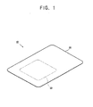
- FIG. 1 is a schematic view showing a configuration of a conventional temperature control pouch pack
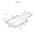
- FIG. 2 is a perspective view of another conventional heating pack
- FIG. 3 is an exploded perspective view showing an interior configuration of FIG. 2 ;
- FIG. 4 is a sectional view taken along line IV-IV of FIG 2 ;
- FIG. 5 is a perspective view showing a configuration of a further conventional a temperature control pouch pack.
- FIG. 6 is a an exploded perspective view showing the configuration of the temperature control pouch pack of FIG. 5 ;
- FIG. 7 is a sectional view taken along line VII-VII of FIG. 5 ;
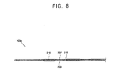
- FIG. 8 is a sectional view taken along line VIII-VIII of FIG. 5 ;
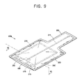
- FIG. 9 is a perspective view showing a configuration of a temperature control pouch pack according to an exemplary embodiment of the present invention.
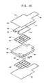
- FIG. 10 is an exploded perspective view of the configuration of the temperature control pouch pack according to the exemplary embodiment of the present invention.
- FIG. 11 is a sectional view taken along line XI-XI of FIG. 9 ;
- FIG. 12 is a perspective view of a temperature control pouch pack according to another exemplary embodiment of the present invention.
- FIGS. 2 through 4 are a perspective view and a sectional view that illustrate a configuration of a conventional temperature control pouch pack 100.
- the temperature control pouch pack 100 includes a first pack 200 which accommodates a reaction fluid pouch 210 to store a reaction fluid and a reaction material pouch 220 to store a reaction material, and a second pack 400 which is disposed to exchange heat with the first pack 200 and contains article to be cooled and heated by endothermic and exothermic reactions between the reaction material and the reaction fluid.
- the reaction fluid pouch 210 stores the reaction fluid therein to chemical-react with the reaction material.
- the reaction fluid may be changed according to the endothermic reaction, the exothermic reaction, and kinds of the reaction material.
- water is used as the reaction fluid.
- NaCl water solution may be used as the reaction fluid.
- the reaction fluid may include an additive to control its melting point (freezing point), and a catalyst to control its reaction rate.
- MgCl may be added to the reaction fluid (i.e., water) so that the freezing point of water is lowered, thereby preventing the reaction fluid from being easily frozen at a relatively low temperature region.
- the reaction fluid pouch 210 is provided with a tearing member 211 on one side thereof to make the reaction fluid flow out of the reaction fluid pouch 210 and react with the reaction material of the reaction material pouch 220.
- the tearing member 211 is connected to a cutting part 215a cut from an edge 215 of the reaction fluid pouch 210, and tears the reaction fluid pouch 210 when a user pulls it outward, thereby reacting the reaction fluid with the reaction material.
- another means may be used instead of the tearing member 211 shown in FIG. 3 as long as it tears the reaction fluid pouch 210 and makes the reaction fluid react with the reaction material.
- a user can tear the reaction fluid pouch 210 by pressing the temperature control pouch pack 100 at both sides without a separate tearing member 211, thereby causing the chemical reaction.
- the edge 215 of the reaction fluid pouch 210 may be sealed with a weak force to thereby allow a user to easily tear the reaction fluid pouch 210.
- the reaction fluid pouch 210 protects the reaction fluid from damage due to external shock and isolates the reaction material from the reaction fluid.
- the reaction fluid pouch 210 is manufactured with a packing material which has a plurality of layers.
- the packing material may include one of linear-low density polyethylene (LLDPE), nylon (NY), aluminum foil (Al), and easy-cut nylon (EZ.NY).
- LLDPE linear-low density polyethylene
- NY nylon
- Al aluminum foil
- EZ.NY easy-cut nylon
- the reaction fluid pouch 210 is filled with the reaction fluid in a reaction fluid storing area 212, and sealed by heat in the other area.
- reaction fluid pouch 210 may be replaced with any means as long as it can store the fluid.
- the reaction material pouch 220 accommodates the reaction material as shown in FIG. 3 .
- the reaction material pouch 220 may be made of a textile non-woven fabric, a pulp non-woven fabric, a foaming resin sheet, etc. to absorb the reaction fluid and adjust a reaction time of the reaction material.
- the reaction material pouch 220 may be partitioned into predetermined areas to prevent the reaction material from making a lump during custody. Accordingly, the reaction material is stored in each partitioned area 221 as shown in FIG. 3 .
- reaction material pouch 220 is coupled to the first pack 200 in order to keep its position while the reaction material reacts with the reaction fluid.
- the reaction material pouch 200 is coupled to a center region of the first pack 200, where a surface to contact the article is relatively large, so as to increase heat transfer efficiency for the article contained in the second pack 400.
- the reaction material employs a heating agent for causing the exothermic reaction with the reaction fluid.
- the heating element includes metal such as magnesium (Mg) and iron (Fe), or calcium oxide.
- the reaction material employs a cooling agent for causing the endothermic reaction with the reaction fluid.
- the cooling agent includes ammonium nitrate, sodium acetate, urea, etc.
- other know compounds causing the endothermic reaction with the reaction fluid may be used.
- each cooling agent may be separately wrapped to prevent the cooling agents from reacting with each other. That is, each cooling agent may be separately wrapped with a watersoluble film.
- the first pack 200 accommodates the reaction material pouch 220 and the reaction fluid pouch 210, and is disposed to exchange heat with the second pack 400.
- the first pack 200 is provided for preventing the reaction fluid from leakage while the reaction material chemically reacts with the reaction fluid.
- the first pack 200 may further include an absorption member to prevent the reaction fluid from leakage. Tissue paper, a non-woven fabric, a sponge, etc. may be used as the absorption member.
- the second pack 400 is attached to an edge region of the first pack 200 and forms a storage space S to store the article.
- the second pack 400 is sealed in the state that the article is contained therein, or opened with an opening 410 (refer to FIG. 2 ) through which the article is taken in and out.
- the temperature control pouch pack 100 according to an exemplary embodiment of the present invention comprises the opening 410 at a lower region thereof, but not limited thereto.
- the opening 410 may be provided at a lateral side of the second pack 400 as necessary.
- the opening 410 may be opened/closed by a zipper or a button to reduce heat loss at the exothermic or endothermic reaction.
- the article to be stored in the second pack 400 includes one of food, beverages, a poultice for cooling a wound of the wounded, and a mask pack for skin care.
- An example of how to use the temperature control pouch pack 100 is as follows. First, a user tears a notch 205 of the first pack 200 to expose the tearing member 211 to the outside. When the tearing member 211 is pressed, the reaction liquid pouch 210 is torn so that the reaction liquid and the reaction material are chemically reacted with each other, thereby causing the endothermic reaction or the exothermic reaction. Accordingly, the inside temperature of the first pack 200 increases or decreases, thereby increasing or decreasing the temperature of the article filled in the second pack 400 being in heat-exchangeable contact with the first pack 200.
- the temperature control pouch pack 100 integrally accommodates the article therein, and is thus convenient for a user to carry it. Further, the heat or the cold generated by the chemical reaction between the reaction fluid and the reaction material can be rapidly transferred to the second pack contacting the first pack, so that the article can quickly reach a desired temperature.
- FIGS. 5 through 8 are perspective views and sectional views of a further conventional temperature control pouch pack 100a.
- repetitive descriptions to the temperature control pouch pack 100 according to the first exemplary embodiment will be avoided as necessary.
- the temperature control pouch pack 100a according to the second exemplary embodiment of the present invention further includes a third pack 300 opposite to a first pack 200 with a second pack 400 therebetween to accommodate the article.
- the third pack 300 includes a reaction fluid pouch 310 to be filled with a reaction fluid, and a reaction material pouch 320 to be filled with a reaction material.
- the reaction material pouch 320 is arranged to contact the article of the second pack 400.
- the temperature control pouch pack 100a includes through holes 213 and 313 provided in edges 215 and 315 of the reaction material pouch 210 and 310 (refer to FIG. 6 ).
- the through hole 213 is provided in the edge 215 and facilitates adhesion between an interior cover 203 and an exterior cover 207 of a first pack pouch 201 accommodating the reaction fluid pouch 210. That is, as shown in FIG. 8 , when the interior cover 203 and the exterior cover 207 of the first pack pouch 201 are adhered to each other, the interior cover 203 and the exterior cover 207 are in direct contact with each other through the through hole 213, so that adhesive efficiency thereof increases and the interior cover 207 and the exterior cover 207 are prevented from separating from each other.
- the through hole 213 is provided between the interior cover 203 and the exterior cover 207 when the interior cover 203 and the exterior cover 207 are adhered to each other. Accordingly, the position of the reaction fluid pouch 210 is kept even though the reaction fluid pouch 210 is torn by pressing the tearing member 211.
- the size and the number of the through hole 213 may vary depending on the size, the thickness, the material, etc. of the first pack pouch 201.
- the through hole 213 may be plural.
- opposite sides of the article accommodated in the second pack 400 are surrounded with both the first pack 200 and the third pack 300, and the article is cooled by the chemical reactions at both sides, so that it takes relatively short time to the control temperature of the article as compared with the temperature control pouch pack 100 according to the first exemplary embodiment.
- the positions of the reaction fluid pouches 210 and 310 are kept by the through holes 213 and 313 provided in the reaction fluid pouches 210 and 310 even though the tearing members 211 and 311 are pull out.
- FIGS. 9 through 12 are perspective views and a sectional view of a temperature control pouch pack 100b according to an examplary embodiment of the present invention.
- the temperature control pouch pack 100b according to the third exemplary embodiment of the present invention includes a second pack 400 to accommodate the article; a first pack 200 provided at one side of the second pack 400 and accommodating a reaction fluid pouch 210 filled with a reaction fluid and a reaction material pouch 220 filled with a reaction material; and a third pack 300 provided at the other side of the second pack 400, communicating with the first pack 200 and accommodating a reaction material pouch 320 filled with a reaction material.
- the first pack 200 includes the reaction fluid pouch 210 to be torn by pressure of a user, and the reaction material pouch 220 to chemically react with the reaction fluid.
- the first pack 200 includes an outlet hole 240 which is formed by perforating one surface 208 of a wrapping contacting the third pack 300 and through which the reaction fluid leaking from the torn reaction fluid pouch 210 flows out.
- an inlet hole 340 is formed on a predetermined region 308 of the third pack 300 in correspondence with the outlet hole 240 of the first pack 200 and allows the reaction fluid leaking through the outlet hole 240 to flow therein. As shown in FIG. 11 , the inlet hole 340 and the outlet hole 240 may be provided to make the reaction fluid directly flow therethrough. Additionally, sealing members (refer to "240a" and "340a” in FIG. 12 ) may be provided around the inlet hole 340 and the outlet hole 240 to prevent leakage of the reaction fluid.
- a communicating member 500 may be separately provided for connecting the inlet hole 340 and the outlet hole 240, so that the reaction fluid can flow through the communicating member 500.
- the sealing members 340a and 240a may be also provided around the inlet hole 340 and the outlet hole 240 to prevent the leakage of the reaction fluid, respectively.
- the third pack 300 includes the reaction material pouch 320 filled with the reaction material to chemically react with the reaction fluid flowed in through the inlet hole 340.
- the inlet hole 340 and the outlet 240 are placed in lower regions of the third pack 300 and the first pack 200, respectively. Accordingly, when the temperature control pouch pack 100b stands, the reaction fluid can flow in the third pack 300 at relatively high speed.
- the reaction fluid flows in both the first pack 200 and the third pack 300 and reacts with the reaction material.
- the article interposed between the first pace 200 and the third pack 300 is heated or cooled.
- the temperature control pouch pack 100b stores a smaller amount of the reaction fluid than that stored in the conventional temperature control pouch pack 100a conventional, so that total weight can decrease, thereby allowing a user to easily carry it.
- the first pack and the third pack are opposite to each other with the second pack accommodating the article therebetween, but not limited thereto.
- a fifth pack and a seventh pack may be added to be opposite to the first pack and the third pack, respectively, in order to cool or heat a plurality of articles at the same time.
Landscapes
- Engineering & Computer Science (AREA)
- Chemical & Material Sciences (AREA)
- Mechanical Engineering (AREA)
- Chemical Kinetics & Catalysis (AREA)
- Combustion & Propulsion (AREA)
- Food Science & Technology (AREA)
- Physics & Mathematics (AREA)
- Thermal Sciences (AREA)
- General Engineering & Computer Science (AREA)
- Life Sciences & Earth Sciences (AREA)
- Cookers (AREA)
- Thermotherapy And Cooling Therapy Devices (AREA)
- Packages (AREA)
- Medical Preparation Storing Or Oral Administration Devices (AREA)
- Control Of Temperature (AREA)
Abstract
Description
- Apparatuses consistent with the present invention relate to a temperature control pouch pack, and more particularly, to a temperature control pouch pack having an improved structure of conveniently heating or cooling an article.
- A temperature control pouch pack is used outdoors to heat or cool an article without additional electronic devices, particularly, used to conveniently heat or cool various beverages and food in winter and summer.
- As shown in
FIG. 1 , a conventional temperaturecontrol pouch pack 10 includes anexternal pack 20 filled with a reaction material which reacts with a reaction fluid, and areaction fluid pouch 30 placed inside theexternal pack 20 and filled with the reaction fluid. In the conventional temperaturecontrol pouch pack 10, if a user presses it and tears thereaction fluid pouch 30, an endothermic or exothermic reaction arises between the reaction fluid and the reaction material and cools or heats a surface of the temperature control pouch pack, so that the temperature of the article is controlled by making the temperature control pouch pack contact the article. - A prior art temperature control pouch pack is also shown e.g. in
WO 01/04548 A1 - However, the conventional temperature
control pouch pack 10 with this configuration should be carried separately from the article, so that it is inconvenient to maintenance and use the conventional temperaturecontrol pouch pack 100. Further, a user should keep the article in contact with the temperaturecontrol pouch pack 10 until the article is cooled or heated to reach a desired temperature, thereby causing inconvenience to him/her. Also, while the article contacts the temperaturecontrol pouch pack 10, a relatively long time may be taken to make the article reach the desired temperature according to heat transfer efficiency of a packing material for the temperaturecontrol pouch pack 10. - Accordingly, it is an aspect of the present invention to provide a temperature control pouch pack which is convenient for heating or cooling article.
- Also, it is another aspect of the present invention to provide a temperature control pouch pack which has high efficiency of temperature control to make article quickly reach a desired temperature.
- Additional aspects of the present invention will be set forth in part in the description which follows and, in part, will be obvious from the description, or may be learned by practice of the present invention.
- The foregoing and/or other aspects of the present invention are achieved by providing a temperature control pouch pack including: a first pack which is filled with a predetermined reaction fluid and a reaction material that react with each other to cause a certain reaction while isolating one of the reaction fluid and the reaction material from the other one; and a second pack which is disposed to exchange heat with the first pack and accommodates an article of which temperature is in need of control.
- According to the invention, the temperature control pouch pack further includes a third pack which communicate with the first pack with the second pack interposed therebetween, in which the third pack being filled with a second reaction material that reacts with the reaction fluid flowed out from the first pack and causes a predetermined reaction.
- According to an aspect of the invention, the second pack includes an opening through which the article is taken in and out, and the opening is provided at a lower region or a lateral side of the second pack.
- According to an aspect of the invention, the first pouch pack and the second pouch pack include reaction fluid pouches to accommodate the reaction fluid, respectively.
- According to an aspect of the invention, the reaction fluid pouch includes a tearing member on a surface thereof to be torn by pressure.
- According to an aspect of the invention, the first pack and the third pack include pack pouches to accommodate the reaction fluid pouch and the reaction material pouch, and the reaction fluid pouch is formed with a through hole which is interposed between the pack pouches at least one region of an adhesive edge and allows the pack pouches to contact with and adhered to each other.
- According to an aspect of the invention, the pack pouches are adhered to each other by one of thermal bolding, high frequency bonding and adhesive.
- According to an aspect of the invention, the through hole is plural.
- According to an aspect of the invention, the first reaction material and the second reaction material are filled in the reaction material pouch which is capable of absorbing the reaction fluid and is partitioned into a plurality of regions.
- According to an aspect of the invention, the first pack includes an outlet hole through which the reaction fluid flows out, and the third pack includes an inlet hole through which the reaction fluid flows in.
- According to an aspect of the invention, the outlet hole of the first pack and the inlet hole of the third pack are in contact with each other so that the reaction fluid communicates with the inlet hole via the outlet hole.
- According to an aspect of the invention, the temperature control pouch pack further includes a communicating member which connects the inlet hole of the first pack and the outlet hole of the third pack and through which the reaction fluid flows.
- According to an aspect of the invention, the temperature control pouch pack further includes a sealing member which is provided around the outlet hole of the first pack and the inlet hole of the second pack and prevents the reaction fluid from leaking while flowing.
- According to an aspect of the invention, the first pack and the third pack include an adhesion region where they are adhered to each other, and the outlet hole and the inlet hole are adjacent to the adhesion region.
- According to an aspect of the invention, the outlet hole and the inlet hole are placed in lower regions of the first pack and the third pack.
- According to an aspect of the invention, the certain reaction is an endothermic reaction, and the first reaction material and the second reaction material include at least one of ammonium nitrate (NH4NO3) and sodium acetate(NaOAc).
- According to an aspect of the invention, the first reaction material and the second reaction material include urea.
- According to an aspect of the invention, the certain reaction is an exothermic reaction, and the first reaction material and the second reaction material include at least one of a metallic heating element and calcium oxide.
- The above and/or other aspects of the present invention will become apparent and more readily appreciated from the following description of the embodiments, taken in conjunction with the accompany drawings of which:
-
FIG. 1 is a schematic view showing a configuration of a conventional temperature control pouch pack; -
FIG. 2 is a perspective view of another conventional heating pack; -
FIG. 3 is an exploded perspective view showing an interior configuration ofFIG. 2 ; -
FIG. 4 is a sectional view taken along line IV-IV ofFIG 2 ; -
FIG. 5 is a perspective view showing a configuration of a further conventional a temperature control pouch pack. -
FIG. 6 is a an exploded perspective view showing the configuration of the temperature control pouch pack ofFIG. 5 ; -
FIG. 7 is a sectional view taken along line VII-VII ofFIG. 5 ; -
FIG. 8 is a sectional view taken along line VIII-VIII ofFIG. 5 ; -
FIG. 9 is a perspective view showing a configuration of a temperature control pouch pack according to an exemplary embodiment of the present invention; -
FIG. 10 is an exploded perspective view of the configuration of the temperature control pouch pack according to the exemplary embodiment of the present invention; -
FIG. 11 is a sectional view taken along line XI-XI ofFIG. 9 ; and -
FIG. 12 is a perspective view of a temperature control pouch pack according to another exemplary embodiment of the present invention. -
FIGS. 2 through 4 are a perspective view and a sectional view that illustrate a configuration of a conventional temperaturecontrol pouch pack 100. As shown therein, the temperaturecontrol pouch pack 100 includes afirst pack 200 which accommodates areaction fluid pouch 210 to store a reaction fluid and areaction material pouch 220 to store a reaction material, and asecond pack 400 which is disposed to exchange heat with thefirst pack 200 and contains article to be cooled and heated by endothermic and exothermic reactions between the reaction material and the reaction fluid. - The
reaction fluid pouch 210 stores the reaction fluid therein to chemical-react with the reaction material. The reaction fluid may be changed according to the endothermic reaction, the exothermic reaction, and kinds of the reaction material. In general, water is used as the reaction fluid. In the case of the exothermic reaction, NaCl water solution may be used as the reaction fluid. Further, the reaction fluid may include an additive to control its melting point (freezing point), and a catalyst to control its reaction rate. For example, in the case of the exothermic reaction, MgCl may be added to the reaction fluid (i.e., water) so that the freezing point of water is lowered, thereby preventing the reaction fluid from being easily frozen at a relatively low temperature region. - The
reaction fluid pouch 210 is provided with a tearingmember 211 on one side thereof to make the reaction fluid flow out of thereaction fluid pouch 210 and react with the reaction material of thereaction material pouch 220. The tearingmember 211 is connected to acutting part 215a cut from anedge 215 of thereaction fluid pouch 210, and tears thereaction fluid pouch 210 when a user pulls it outward, thereby reacting the reaction fluid with the reaction material. Alternatively, another means may be used instead of the tearingmember 211 shown inFIG. 3 as long as it tears thereaction fluid pouch 210 and makes the reaction fluid react with the reaction material. - For example, according to an exemplary embodiment of the present invention, a user can tear the
reaction fluid pouch 210 by pressing the temperaturecontrol pouch pack 100 at both sides without aseparate tearing member 211, thereby causing the chemical reaction. At this time, theedge 215 of thereaction fluid pouch 210 may be sealed with a weak force to thereby allow a user to easily tear thereaction fluid pouch 210. - The
reaction fluid pouch 210 protects the reaction fluid from damage due to external shock and isolates the reaction material from the reaction fluid. Thereaction fluid pouch 210 is manufactured with a packing material which has a plurality of layers. The packing material may include one of linear-low density polyethylene (LLDPE), nylon (NY), aluminum foil (Al), and easy-cut nylon (EZ.NY). Thereaction fluid pouch 210 is filled with the reaction fluid in a reaction fluid storingarea 212, and sealed by heat in the other area. - Meanwhile, the
reaction fluid pouch 210 may be replaced with any means as long as it can store the fluid. - The
reaction material pouch 220 accommodates the reaction material as shown inFIG. 3 . Here, thereaction material pouch 220 may be made of a textile non-woven fabric, a pulp non-woven fabric, a foaming resin sheet, etc. to absorb the reaction fluid and adjust a reaction time of the reaction material. Further, thereaction material pouch 220 may be partitioned into predetermined areas to prevent the reaction material from making a lump during custody. Accordingly, the reaction material is stored in eachpartitioned area 221 as shown inFIG. 3 . - It is preferable but not necessary that the
reaction material pouch 220 is coupled to thefirst pack 200 in order to keep its position while the reaction material reacts with the reaction fluid. Particularly, thereaction material pouch 200 is coupled to a center region of thefirst pack 200, where a surface to contact the article is relatively large, so as to increase heat transfer efficiency for the article contained in thesecond pack 400. - To heat the article, the reaction material employs a heating agent for causing the exothermic reaction with the reaction fluid. For example, the heating element includes metal such as magnesium (Mg) and iron (Fe), or calcium oxide.
- On the other hand, to cool the article, the reaction material employs a cooling agent for causing the endothermic reaction with the reaction fluid. For example, the cooling agent includes ammonium nitrate, sodium acetate, urea, etc. Further, other know compounds causing the endothermic reaction with the reaction fluid may be used.
- If the
reaction material pouch 220 stores different cooling agents all together, each cooling agent may be separately wrapped to prevent the cooling agents from reacting with each other. That is, each cooling agent may be separately wrapped with a watersoluble film. - As shown in
FIG. 1 , thefirst pack 200 accommodates thereaction material pouch 220 and thereaction fluid pouch 210, and is disposed to exchange heat with thesecond pack 400. Thefirst pack 200 is provided for preventing the reaction fluid from leakage while the reaction material chemically reacts with the reaction fluid. At this time, thefirst pack 200 may further include an absorption member to prevent the reaction fluid from leakage. Tissue paper, a non-woven fabric, a sponge, etc. may be used as the absorption member. - The
second pack 400 is attached to an edge region of thefirst pack 200 and forms a storage space S to store the article. Thesecond pack 400 is sealed in the state that the article is contained therein, or opened with an opening 410 (refer toFIG. 2 ) through which the article is taken in and out. The temperaturecontrol pouch pack 100 according to an exemplary embodiment of the present invention comprises theopening 410 at a lower region thereof, but not limited thereto. Alternatively, theopening 410 may be provided at a lateral side of thesecond pack 400 as necessary. Further, theopening 410 may be opened/closed by a zipper or a button to reduce heat loss at the exothermic or endothermic reaction. - Meanwhile, the article to be stored in the
second pack 400 includes one of food, beverages, a poultice for cooling a wound of the wounded, and a mask pack for skin care. - An example of how to use the temperature
control pouch pack 100 is as follows. First, a user tears anotch 205 of thefirst pack 200 to expose the tearingmember 211 to the outside. When the tearingmember 211 is pressed, the reactionliquid pouch 210 is torn so that the reaction liquid and the reaction material are chemically reacted with each other, thereby causing the endothermic reaction or the exothermic reaction. Accordingly, the inside temperature of thefirst pack 200 increases or decreases, thereby increasing or decreasing the temperature of the article filled in thesecond pack 400 being in heat-exchangeable contact with thefirst pack 200. - As described above, the temperature
control pouch pack 100 according to an exemplary embodiment of the present invention integrally accommodates the article therein, and is thus convenient for a user to carry it. Further, the heat or the cold generated by the chemical reaction between the reaction fluid and the reaction material can be rapidly transferred to the second pack contacting the first pack, so that the article can quickly reach a desired temperature. - Meanwhile,
FIGS. 5 through 8 are perspective views and sectional views of a further conventional temperaturecontrol pouch pack 100a. Here, repetitive descriptions to the temperaturecontrol pouch pack 100 according to the first exemplary embodiment will be avoided as necessary. - As shown therein, the temperature
control pouch pack 100a according to the second exemplary embodiment of the present invention further includes athird pack 300 opposite to afirst pack 200 with asecond pack 400 therebetween to accommodate the article. - Like the
first pack 200, thethird pack 300 includes areaction fluid pouch 310 to be filled with a reaction fluid, and areaction material pouch 320 to be filled with a reaction material. Thereaction material pouch 320 is arranged to contact the article of thesecond pack 400. - Further, the temperature
control pouch pack 100a according to the second exemplary embodiment includes throughholes edges reaction material pouch 210 and 310 (refer toFIG. 6 ). - The through
hole 213 is provided in theedge 215 and facilitates adhesion between aninterior cover 203 and anexterior cover 207 of afirst pack pouch 201 accommodating thereaction fluid pouch 210. That is, as shown inFIG. 8 , when theinterior cover 203 and theexterior cover 207 of thefirst pack pouch 201 are adhered to each other, theinterior cover 203 and theexterior cover 207 are in direct contact with each other through the throughhole 213, so that adhesive efficiency thereof increases and theinterior cover 207 and theexterior cover 207 are prevented from separating from each other. - Further, the through
hole 213 is provided between theinterior cover 203 and theexterior cover 207 when theinterior cover 203 and theexterior cover 207 are adhered to each other. Accordingly, the position of thereaction fluid pouch 210 is kept even though thereaction fluid pouch 210 is torn by pressing the tearingmember 211. - The size and the number of the through
hole 213 may vary depending on the size, the thickness, the material, etc. of thefirst pack pouch 201. For adhesive efficiency, the throughhole 213 may be plural. - In the temperature
control pouch pack 100a with this configuration according to the second exemplary embodiment of the present invention, opposite sides of the article accommodated in thesecond pack 400 are surrounded with both thefirst pack 200 and thethird pack 300, and the article is cooled by the chemical reactions at both sides, so that it takes relatively short time to the control temperature of the article as compared with the temperaturecontrol pouch pack 100 according to the first exemplary embodiment. Further, the positions of thereaction fluid pouches holes reaction fluid pouches members - In the meantime,
FIGS. 9 through 12 are perspective views and a sectional view of a temperaturecontrol pouch pack 100b according to an examplary embodiment of the present invention. As shown therein, the temperaturecontrol pouch pack 100b according to the third exemplary embodiment of the present invention includes asecond pack 400 to accommodate the article; afirst pack 200 provided at one side of thesecond pack 400 and accommodating areaction fluid pouch 210 filled with a reaction fluid and areaction material pouch 220 filled with a reaction material; and athird pack 300 provided at the other side of thesecond pack 400, communicating with thefirst pack 200 and accommodating areaction material pouch 320 filled with a reaction material. - The
first pack 200 includes thereaction fluid pouch 210 to be torn by pressure of a user, and thereaction material pouch 220 to chemically react with the reaction fluid. Thefirst pack 200 includes anoutlet hole 240 which is formed by perforating onesurface 208 of a wrapping contacting thethird pack 300 and through which the reaction fluid leaking from the torn reactionfluid pouch 210 flows out. - Further, an
inlet hole 340 is formed on apredetermined region 308 of thethird pack 300 in correspondence with theoutlet hole 240 of thefirst pack 200 and allows the reaction fluid leaking through theoutlet hole 240 to flow therein. As shown inFIG. 11 , theinlet hole 340 and theoutlet hole 240 may be provided to make the reaction fluid directly flow therethrough. Additionally, sealing members (refer to "240a" and "340a" inFIG. 12 ) may be provided around theinlet hole 340 and theoutlet hole 240 to prevent leakage of the reaction fluid. - As shown in
FIG. 12 , a communicatingmember 500 may be separately provided for connecting theinlet hole 340 and theoutlet hole 240, so that the reaction fluid can flow through the communicatingmember 500. Likewise, the sealingmembers inlet hole 340 and theoutlet hole 240 to prevent the leakage of the reaction fluid, respectively. - The
third pack 300 includes thereaction material pouch 320 filled with the reaction material to chemically react with the reaction fluid flowed in through theinlet hole 340. - Here, it is preferable but not necessary that the
inlet hole 340 and theoutlet 240 are placed in lower regions of thethird pack 300 and thefirst pack 200, respectively. Accordingly, when the temperaturecontrol pouch pack 100b stands, the reaction fluid can flow in thethird pack 300 at relatively high speed. - In the temperature
control pouch pack 100b with this configuration according to the third exemplary embodiment of the present invention, when a user presses and tears the tearingmember 211, the reaction fluid flows in both thefirst pack 200 and thethird pack 300 and reacts with the reaction material. Thus, the article interposed between thefirst pace 200 and thethird pack 300 is heated or cooled. - As described above, the temperature
control pouch pack 100b according the exemplary embodiment of the present invention stores a smaller amount of the reaction fluid than that stored in the conventional temperaturecontrol pouch pack 100a conventional, so that total weight can decrease, thereby allowing a user to easily carry it. - In the exemplary embodiments of the present invention, the first pack and the third pack are opposite to each other with the second pack accommodating the article therebetween, but not limited thereto. Alternatively, a fifth pack and a seventh pack may be added to be opposite to the first pack and the third pack, respectively, in order to cool or heat a plurality of articles at the same time.
Claims (13)
- A temperature control pouch pack (100b) comprising:a first pack (200) which is filled with a predetermined reaction fluid and a first reaction material reactable with each other to cause a certain reaction said first pack (200) isolating one of the reaction fluid and the first reaction material from the other one; anda second pack (400) which is disposed to exchange heat with the first pack (200) and capable of accommodating an article of which temperature is in need of control; andcharacterized by further comprisinga third pack (300) which communicates with the first pack (200) with the second pack (400) interposed therebetween,the third pack (300) being filled with a second reaction material reactable with the reaction fluid having flowed out from the first pack (200) and thereby causing a predetermined reaction.
- The temperature control pouch pack (100b) according to claim 1, wherein
the second pack (400) comprises an opening (410) through which the article can be taken in and out, and
the opening (410) being provided at a lower region or a lateral side of the second pack (400). - The temperature control pouch pack (100b) according to claim 1, wherein the first pack (200) and the third pack (300) each comprise a reaction fluid pouch (210, 310) to accommodate the reaction fluid, respectively.
- The temperature control pouch pack (100b) according to claim 3, wherein the reaction fluid pouch (210, 310) comprises a tearing member (211, 311) on a surface (208) thereof to be torn by pressure.
- The temperature control pouch pack (100b) according to claim 4, wherein the first pack (200) and the third pack (300) comprise pack pouches (201) to accommodate the reaction fluid pouch (210, 310) and the reaction material pouch (220, 320), and
the reaction fluid pouch (210, 310) is formed with a through hole (213, 313) which is interposed between the pack pouches (201) in at least one region of an adhesive edge (215, 315) and allows the pack pouches (201) to be in contact with and to be adhered to each other. - The temperature control pouch pack (100b) according to claim 1, wherein the first reaction material and the second reaction material are filled in the reaction material pouch (220, 320) which is capable of absorbing the reaction fluid and is partitioned into a plurality of regions.
- The temperature control pouch pack (100b) according to claim 1, wherein the first pack (200) comprises an outlet hole (240) through which the reaction fluid is capable of flowing out, and the third pack (300) comprises an inlet hole (340) through which the reaction fluid is capable of flowing in.
- The temperature control pouch pack (100b) according to claim 7, wherein the outlet hole (240) of the first pack (200) and the inlet hole (340) of the third pack (300) are in contact with each other so that the reaction fluid communicates with the inlet hole (340) via the outlet hole (240).
- The temperature control pouch pack (100b) according to claim 7, further comprising a communicating member (500) which connects the outlet hole (240) of the first pack (200) and the inlet hole (340) of the third pack (300) and through which the reaction fluid is capable of flowing.
- The temperature control pouch pack (100b) according to any one of claims 7 through 9, further comprising a sealing member (240a, 340a) which is provided around the outlet hole (240) of the first pack (200) and the inlet hole (340) of the third pack (300) and capable of preventing the reaction fluid from leaking while flowing.
- The temperature control pouch pack (100b) according to claim 7, wherein the first pack (200) and the third pack (300) comprise an adhesion region where they are adhered to each other, and
the outlet hole (240) and the inlet hole (340) are adjacent to the adhesion region. - The temperature control pouch pack (100b) according to claim 1, wherein the certain reaction is an endothermic reaction, and
the first reaction material and the second reaction material include at least one of ammonium nitrate (NH4NO3) and sodium acetate(NaOAc). - The temperature control pouch pack (100b) according to claim 1, wherein the certain reaction is an exothermic reaction, and
the first reaction material and the second reaction material include at least one of a metallic heating element and calcium oxide.
Applications Claiming Priority (4)
| Application Number | Priority Date | Filing Date | Title |
|---|---|---|---|
| KR1020060018345A KR100869056B1 (en) | 2006-02-24 | 2006-02-24 | Heating Pack Unit |
| KR1020060018346A KR101018831B1 (en) | 2006-02-24 | 2006-02-24 | Heating Pack Unit |
| KR1020060110210A KR100821169B1 (en) | 2006-11-08 | 2006-11-08 | Cooling Pack Unit |
| PCT/KR2007/000959 WO2007097591A1 (en) | 2006-02-24 | 2007-02-23 | Pouch pack controlling temperature |
Publications (3)
| Publication Number | Publication Date |
|---|---|
| EP1986533A1 EP1986533A1 (en) | 2008-11-05 |
| EP1986533A4 EP1986533A4 (en) | 2010-02-10 |
| EP1986533B1 true EP1986533B1 (en) | 2011-11-02 |
Family
ID=38437589
Family Applications (1)
| Application Number | Title | Priority Date | Filing Date |
|---|---|---|---|
| EP07709084A Active EP1986533B1 (en) | 2006-02-24 | 2007-02-23 | Pouch pack with controlled temperature |
Country Status (5)
| Country | Link |
|---|---|
| US (1) | US8118021B2 (en) |
| EP (1) | EP1986533B1 (en) |
| JP (1) | JP4887382B2 (en) |
| AT (1) | ATE531301T1 (en) |
| WO (1) | WO2007097591A1 (en) |
Families Citing this family (20)
| Publication number | Priority date | Publication date | Assignee | Title |
|---|---|---|---|---|
| US20070289720A1 (en) * | 2005-12-13 | 2007-12-20 | University Of South Florida | Self-Heating Chemical System for Sustained Modulation of Temperature |
| CA2793587C (en) | 2009-03-19 | 2016-01-19 | Daniel Young | Pouch for internal mixture of segregated reactants and applications thereof |
| KR100967452B1 (en) * | 2009-04-21 | 2010-07-01 | 주식회사 크라우젠 | Flameless heating pack |
| US8635998B2 (en) * | 2009-06-02 | 2014-01-28 | Read Manufacturing Company | Tunable flameless heaters |
| US20150168045A1 (en) * | 2011-08-29 | 2015-06-18 | Ruthanne Schmitz | Cold Wrap for Beverage Keg |
| JP6017562B2 (en) | 2011-09-06 | 2016-11-02 | ブリティッシュ アメリカン タバコ (インヴェストメンツ) リミテッドBritish American Tobacco (Investments) Limited | Smoking material heating |
| WO2013034459A1 (en) | 2011-09-06 | 2013-03-14 | British American Tobacco (Investments) Limited | Heating smokeable material |
| DE102012007697A1 (en) * | 2012-04-19 | 2015-08-13 | Fresenius Medical Care Deutschland Gmbh | Bag with flow compensation |
| GB201207039D0 (en) | 2012-04-23 | 2012-06-06 | British American Tobacco Co | Heating smokeable material |
| ITRM20130234A1 (en) * | 2013-04-18 | 2014-10-19 | Stefano Montellanico | KIT FOR THERMAL TREATMENT OF FOODS. |
| GB201311620D0 (en) * | 2013-06-28 | 2013-08-14 | British American Tobacco Co | Devices Comprising a Heat Source Material and Activation Chambers for the Same |
| GB201500582D0 (en) | 2015-01-14 | 2015-02-25 | British American Tobacco Co | Apparatus for heating or cooling a material contained therein |
| GB201511361D0 (en) | 2015-06-29 | 2015-08-12 | Nicoventures Holdings Ltd | Electronic vapour provision system |
| GB201511349D0 (en) | 2015-06-29 | 2015-08-12 | Nicoventures Holdings Ltd | Electronic aerosol provision systems |
| US11924930B2 (en) | 2015-08-31 | 2024-03-05 | Nicoventures Trading Limited | Article for use with apparatus for heating smokable material |
| US20170055584A1 (en) | 2015-08-31 | 2017-03-02 | British American Tobacco (Investments) Limited | Article for use with apparatus for heating smokable material |
| US9930945B2 (en) * | 2015-10-08 | 2018-04-03 | Nice Touch, LLC | Systems and methods for a protective sleeve for electronic devices |
| US20170119046A1 (en) | 2015-10-30 | 2017-05-04 | British American Tobacco (Investments) Limited | Apparatus for Heating Smokable Material |
| EP3655713B1 (en) * | 2017-07-20 | 2021-11-24 | Tempra Technology, Inc. | Self-heating food pouch with distributed reactants and method of manufacturing |
| US11140797B1 (en) * | 2020-07-31 | 2021-10-05 | Tamara Phipps | Apparatus for enhancing cooling of an electronic computing device and method of use |
Family Cites Families (13)
| Publication number | Priority date | Publication date | Assignee | Title |
|---|---|---|---|---|
| US3542032A (en) * | 1968-03-22 | 1970-11-24 | Cramer Products Inc | Therapy package |
| US6116231A (en) | 1998-02-11 | 2000-09-12 | Tempra Technology, Inc. | Liquid heat pack |
| US6247469B1 (en) * | 1998-10-26 | 2001-06-19 | Tony Michael Guard | Warmer for a sporting element |
| US6393843B2 (en) * | 1999-03-06 | 2002-05-28 | Allegiance Corporation | Extended life thermal pack |
| US6289889B1 (en) * | 1999-07-12 | 2001-09-18 | Tda Research, Inc. | Self-heating flexible package |
| US7922984B2 (en) * | 2000-02-18 | 2011-04-12 | Selective Micro Technologies, Llc | Apparatus and method for controlled delivery of a gas |
| CA2401831C (en) * | 2000-03-02 | 2007-12-11 | Tempra Technology Inc. | Portable heating/cooling and dispensing devices |
| DE10032799B4 (en) * | 2000-06-28 | 2005-09-22 | Coty B.V. | Multi-chamber packaging for cooling or heating products |
| US6484514B1 (en) | 2000-10-10 | 2002-11-26 | The Procter & Gamble Company | Product dispenser having internal temperature changing element |
| JP2004534699A (en) * | 2001-06-29 | 2004-11-18 | ザ プロクター アンド ギャンブル カンパニー | Self-heating / self-cooling package |
| US6640801B2 (en) * | 2001-08-29 | 2003-11-04 | Tempra Technology, Inc. | Heat pack with expansion capability |
| KR200300703Y1 (en) * | 2002-09-26 | 2003-01-14 | 김순일 | Chinese medicine automatic heating packaging container. |
| KR100601077B1 (en) * | 2004-03-17 | 2006-07-19 | 김순일 | Automatic Heating Pouch Pack |
-
2007
- 2007-02-23 JP JP2008556253A patent/JP4887382B2/en active Active
- 2007-02-23 WO PCT/KR2007/000959 patent/WO2007097591A1/en not_active Ceased
- 2007-02-23 US US12/280,431 patent/US8118021B2/en active Active
- 2007-02-23 EP EP07709084A patent/EP1986533B1/en active Active
- 2007-02-23 AT AT07709084T patent/ATE531301T1/en active
Also Published As
| Publication number | Publication date |
|---|---|
| US8118021B2 (en) | 2012-02-21 |
| JP2009527724A (en) | 2009-07-30 |
| WO2007097591A1 (en) | 2007-08-30 |
| JP4887382B2 (en) | 2012-02-29 |
| US20090025706A1 (en) | 2009-01-29 |
| ATE531301T1 (en) | 2011-11-15 |
| EP1986533A1 (en) | 2008-11-05 |
| EP1986533A4 (en) | 2010-02-10 |
Similar Documents
| Publication | Publication Date | Title |
|---|---|---|
| US8118021B2 (en) | Pouch pack controlling temperature | |
| US9334087B2 (en) | Standing pouch | |
| US20050224388A1 (en) | Self-heating pre-moistened wipe(s) package | |
| CN101389248B (en) | Temperature-controlled pouch packaging | |
| US6644383B2 (en) | Self-heating/self-cooling package | |
| US7243509B2 (en) | Thermal therapeutic method | |
| JP6159314B2 (en) | Pouch | |
| JP2004512868A (en) | Product dispenser with internal temperature change element | |
| EP1218261A1 (en) | Temperature change pouch with dispensing chamber | |
| JP2012025394A (en) | Method of manufacturing self-supporting container | |
| US5641325A (en) | Ice pack | |
| KR101000509B1 (en) | Standing pouch | |
| EP3655713B1 (en) | Self-heating food pouch with distributed reactants and method of manufacturing | |
| JP2015536282A (en) | Upright pouch | |
| KR200336223Y1 (en) | Flameless heater | |
| JP4296316B2 (en) | Non-flame heater | |
| KR101286510B1 (en) | Pouch | |
| KR100429328B1 (en) | Flameless heater | |
| JP7194373B2 (en) | packaging bag | |
| KR20100019923A (en) | Thermostatic Pouch Pack | |
| KR101018831B1 (en) | Heating Pack Unit | |
| KR200264438Y1 (en) | Flameless heater | |
| JP4919221B2 (en) | Sheet cosmetic packaging | |
| JP5420041B2 (en) | Cold insulator, bag for cold insulator and method of using cold insulator | |
| EP4618818A1 (en) | Cold weather oxygen activated heater |
Legal Events
| Date | Code | Title | Description |
|---|---|---|---|
| PUAI | Public reference made under article 153(3) epc to a published international application that has entered the european phase |
Free format text: ORIGINAL CODE: 0009012 |
|
| 17P | Request for examination filed |
Effective date: 20080822 |
|
| AK | Designated contracting states |
Kind code of ref document: A1 Designated state(s): AT BE BG CH CY CZ DE DK EE ES FI FR GB GR HU IE IS IT LI LT LU LV MC NL PL PT RO SE SI SK TR |
|
| A4 | Supplementary search report drawn up and despatched |
Effective date: 20100112 |
|
| RIC1 | Information provided on ipc code assigned before grant |
Ipc: B65D 81/34 20060101ALI20100105BHEP Ipc: A47J 36/30 20060101AFI20070927BHEP Ipc: A47J 36/28 20060101ALI20100105BHEP |
|
| 17Q | First examination report despatched |
Effective date: 20100408 |
|
| RIC1 | Information provided on ipc code assigned before grant |
Ipc: A47J 36/28 20060101ALI20101004BHEP Ipc: B65D 81/34 20060101ALI20101004BHEP Ipc: A47J 36/30 20060101AFI20101004BHEP |
|
| RTI1 | Title (correction) |
Free format text: POUCH PACK WITH CONTROLLED TEMPERATURE |
|
| GRAP | Despatch of communication of intention to grant a patent |
Free format text: ORIGINAL CODE: EPIDOSNIGR1 |
|
| GRAS | Grant fee paid |
Free format text: ORIGINAL CODE: EPIDOSNIGR3 |
|
| GRAA | (expected) grant |
Free format text: ORIGINAL CODE: 0009210 |
|
| DAX | Request for extension of the european patent (deleted) | ||
| AK | Designated contracting states |
Kind code of ref document: B1 Designated state(s): AT BE BG CH CY CZ DE DK EE ES FI FR GB GR HU IE IS IT LI LT LU LV MC NL PL PT RO SE SI SK TR |
|
| REG | Reference to a national code |
Ref country code: GB Ref legal event code: FG4D |
|
| REG | Reference to a national code |
Ref country code: CH Ref legal event code: EP |
|
| REG | Reference to a national code |
Ref country code: IE Ref legal event code: FG4D |
|
| REG | Reference to a national code |
Ref country code: DE Ref legal event code: R096 Ref document number: 602007018442 Country of ref document: DE Effective date: 20120105 |
|
| REG | Reference to a national code |
Ref country code: NL Ref legal event code: VDEP Effective date: 20111102 |
|
| LTIE | Lt: invalidation of european patent or patent extension |
Effective date: 20111102 |
|
| PG25 | Lapsed in a contracting state [announced via postgrant information from national office to epo] |
Ref country code: LT Free format text: LAPSE BECAUSE OF FAILURE TO SUBMIT A TRANSLATION OF THE DESCRIPTION OR TO PAY THE FEE WITHIN THE PRESCRIBED TIME-LIMIT Effective date: 20111102 Ref country code: IS Free format text: LAPSE BECAUSE OF FAILURE TO SUBMIT A TRANSLATION OF THE DESCRIPTION OR TO PAY THE FEE WITHIN THE PRESCRIBED TIME-LIMIT Effective date: 20120302 |
|
| PG25 | Lapsed in a contracting state [announced via postgrant information from national office to epo] |
Ref country code: GR Free format text: LAPSE BECAUSE OF FAILURE TO SUBMIT A TRANSLATION OF THE DESCRIPTION OR TO PAY THE FEE WITHIN THE PRESCRIBED TIME-LIMIT Effective date: 20120203 Ref country code: SE Free format text: LAPSE BECAUSE OF FAILURE TO SUBMIT A TRANSLATION OF THE DESCRIPTION OR TO PAY THE FEE WITHIN THE PRESCRIBED TIME-LIMIT Effective date: 20111102 Ref country code: NL Free format text: LAPSE BECAUSE OF FAILURE TO SUBMIT A TRANSLATION OF THE DESCRIPTION OR TO PAY THE FEE WITHIN THE PRESCRIBED TIME-LIMIT Effective date: 20111102 Ref country code: BE Free format text: LAPSE BECAUSE OF FAILURE TO SUBMIT A TRANSLATION OF THE DESCRIPTION OR TO PAY THE FEE WITHIN THE PRESCRIBED TIME-LIMIT Effective date: 20111102 Ref country code: LV Free format text: LAPSE BECAUSE OF FAILURE TO SUBMIT A TRANSLATION OF THE DESCRIPTION OR TO PAY THE FEE WITHIN THE PRESCRIBED TIME-LIMIT Effective date: 20111102 Ref country code: SI Free format text: LAPSE BECAUSE OF FAILURE TO SUBMIT A TRANSLATION OF THE DESCRIPTION OR TO PAY THE FEE WITHIN THE PRESCRIBED TIME-LIMIT Effective date: 20111102 Ref country code: PT Free format text: LAPSE BECAUSE OF FAILURE TO SUBMIT A TRANSLATION OF THE DESCRIPTION OR TO PAY THE FEE WITHIN THE PRESCRIBED TIME-LIMIT Effective date: 20120302 Ref country code: PL Free format text: LAPSE BECAUSE OF FAILURE TO SUBMIT A TRANSLATION OF THE DESCRIPTION OR TO PAY THE FEE WITHIN THE PRESCRIBED TIME-LIMIT Effective date: 20111102 |
|
| PG25 | Lapsed in a contracting state [announced via postgrant information from national office to epo] |
Ref country code: CY Free format text: LAPSE BECAUSE OF FAILURE TO SUBMIT A TRANSLATION OF THE DESCRIPTION OR TO PAY THE FEE WITHIN THE PRESCRIBED TIME-LIMIT Effective date: 20111102 |
|
| PG25 | Lapsed in a contracting state [announced via postgrant information from national office to epo] |
Ref country code: DK Free format text: LAPSE BECAUSE OF FAILURE TO SUBMIT A TRANSLATION OF THE DESCRIPTION OR TO PAY THE FEE WITHIN THE PRESCRIBED TIME-LIMIT Effective date: 20111102 Ref country code: EE Free format text: LAPSE BECAUSE OF FAILURE TO SUBMIT A TRANSLATION OF THE DESCRIPTION OR TO PAY THE FEE WITHIN THE PRESCRIBED TIME-LIMIT Effective date: 20111102 Ref country code: CZ Free format text: LAPSE BECAUSE OF FAILURE TO SUBMIT A TRANSLATION OF THE DESCRIPTION OR TO PAY THE FEE WITHIN THE PRESCRIBED TIME-LIMIT Effective date: 20111102 Ref country code: SK Free format text: LAPSE BECAUSE OF FAILURE TO SUBMIT A TRANSLATION OF THE DESCRIPTION OR TO PAY THE FEE WITHIN THE PRESCRIBED TIME-LIMIT Effective date: 20111102 Ref country code: BG Free format text: LAPSE BECAUSE OF FAILURE TO SUBMIT A TRANSLATION OF THE DESCRIPTION OR TO PAY THE FEE WITHIN THE PRESCRIBED TIME-LIMIT Effective date: 20120202 |
|
| PG25 | Lapsed in a contracting state [announced via postgrant information from national office to epo] |
Ref country code: IT Free format text: LAPSE BECAUSE OF FAILURE TO SUBMIT A TRANSLATION OF THE DESCRIPTION OR TO PAY THE FEE WITHIN THE PRESCRIBED TIME-LIMIT Effective date: 20111102 Ref country code: RO Free format text: LAPSE BECAUSE OF FAILURE TO SUBMIT A TRANSLATION OF THE DESCRIPTION OR TO PAY THE FEE WITHIN THE PRESCRIBED TIME-LIMIT Effective date: 20111102 |
|
| PLBE | No opposition filed within time limit |
Free format text: ORIGINAL CODE: 0009261 |
|
| STAA | Information on the status of an ep patent application or granted ep patent |
Free format text: STATUS: NO OPPOSITION FILED WITHIN TIME LIMIT |
|
| REG | Reference to a national code |
Ref country code: AT Ref legal event code: MK05 Ref document number: 531301 Country of ref document: AT Kind code of ref document: T Effective date: 20111102 |
|
| PG25 | Lapsed in a contracting state [announced via postgrant information from national office to epo] |
Ref country code: MC Free format text: LAPSE BECAUSE OF NON-PAYMENT OF DUE FEES Effective date: 20120229 |
|
| REG | Reference to a national code |
Ref country code: CH Ref legal event code: PL |
|
| 26N | No opposition filed |
Effective date: 20120803 |
|
| PG25 | Lapsed in a contracting state [announced via postgrant information from national office to epo] |
Ref country code: LI Free format text: LAPSE BECAUSE OF NON-PAYMENT OF DUE FEES Effective date: 20120229 Ref country code: CH Free format text: LAPSE BECAUSE OF NON-PAYMENT OF DUE FEES Effective date: 20120229 |
|
| REG | Reference to a national code |
Ref country code: IE Ref legal event code: MM4A |
|
| REG | Reference to a national code |
Ref country code: DE Ref legal event code: R097 Ref document number: 602007018442 Country of ref document: DE Effective date: 20120803 |
|
| PG25 | Lapsed in a contracting state [announced via postgrant information from national office to epo] |
Ref country code: AT Free format text: LAPSE BECAUSE OF FAILURE TO SUBMIT A TRANSLATION OF THE DESCRIPTION OR TO PAY THE FEE WITHIN THE PRESCRIBED TIME-LIMIT Effective date: 20111102 Ref country code: IE Free format text: LAPSE BECAUSE OF NON-PAYMENT OF DUE FEES Effective date: 20120223 |
|
| PG25 | Lapsed in a contracting state [announced via postgrant information from national office to epo] |
Ref country code: ES Free format text: LAPSE BECAUSE OF FAILURE TO SUBMIT A TRANSLATION OF THE DESCRIPTION OR TO PAY THE FEE WITHIN THE PRESCRIBED TIME-LIMIT Effective date: 20120213 |
|
| PG25 | Lapsed in a contracting state [announced via postgrant information from national office to epo] |
Ref country code: FI Free format text: LAPSE BECAUSE OF FAILURE TO SUBMIT A TRANSLATION OF THE DESCRIPTION OR TO PAY THE FEE WITHIN THE PRESCRIBED TIME-LIMIT Effective date: 20111102 |
|
| PG25 | Lapsed in a contracting state [announced via postgrant information from national office to epo] |
Ref country code: TR Free format text: LAPSE BECAUSE OF FAILURE TO SUBMIT A TRANSLATION OF THE DESCRIPTION OR TO PAY THE FEE WITHIN THE PRESCRIBED TIME-LIMIT Effective date: 20111102 |
|
| PG25 | Lapsed in a contracting state [announced via postgrant information from national office to epo] |
Ref country code: LU Free format text: LAPSE BECAUSE OF NON-PAYMENT OF DUE FEES Effective date: 20120223 |
|
| PG25 | Lapsed in a contracting state [announced via postgrant information from national office to epo] |
Ref country code: HU Free format text: LAPSE BECAUSE OF FAILURE TO SUBMIT A TRANSLATION OF THE DESCRIPTION OR TO PAY THE FEE WITHIN THE PRESCRIBED TIME-LIMIT Effective date: 20070223 |
|
| REG | Reference to a national code |
Ref country code: FR Ref legal event code: PLFP Year of fee payment: 10 |
|
| REG | Reference to a national code |
Ref country code: FR Ref legal event code: PLFP Year of fee payment: 11 |
|
| REG | Reference to a national code |
Ref country code: FR Ref legal event code: PLFP Year of fee payment: 12 |
|
| PGFP | Annual fee paid to national office [announced via postgrant information from national office to epo] |
Ref country code: DE Payment date: 20250122 Year of fee payment: 19 |
|
| PGFP | Annual fee paid to national office [announced via postgrant information from national office to epo] |
Ref country code: FR Payment date: 20250122 Year of fee payment: 19 |
|
| PGFP | Annual fee paid to national office [announced via postgrant information from national office to epo] |
Ref country code: GB Payment date: 20250123 Year of fee payment: 19 |