EP1986058A1 - Hologram recorder - Google Patents
Hologram recorder Download PDFInfo
- Publication number
- EP1986058A1 EP1986058A1 EP06713646A EP06713646A EP1986058A1 EP 1986058 A1 EP1986058 A1 EP 1986058A1 EP 06713646 A EP06713646 A EP 06713646A EP 06713646 A EP06713646 A EP 06713646A EP 1986058 A1 EP1986058 A1 EP 1986058A1
- Authority
- EP
- European Patent Office
- Prior art keywords
- reference beam
- recording area
- unit recording
- tip
- applier
- Prior art date
- Legal status (The legal status is an assumption and is not a legal conclusion. Google has not performed a legal analysis and makes no representation as to the accuracy of the status listed.)
- Granted
Links
- 230000003287 optical effect Effects 0.000 description 12
- 238000000034 method Methods 0.000 description 10
- 238000000926 separation method Methods 0.000 description 8
- 239000000203 mixture Substances 0.000 description 3
- 238000010586 diagram Methods 0.000 description 2
- 239000000470 constituent Substances 0.000 description 1
- 238000010276 construction Methods 0.000 description 1
- 239000004973 liquid crystal related substance Substances 0.000 description 1
- 239000011295 pitch Substances 0.000 description 1
- 229920000642 polymer Polymers 0.000 description 1
- 238000012795 verification Methods 0.000 description 1
Images


Classifications
-
- G—PHYSICS
- G03—PHOTOGRAPHY; CINEMATOGRAPHY; ANALOGOUS TECHNIQUES USING WAVES OTHER THAN OPTICAL WAVES; ELECTROGRAPHY; HOLOGRAPHY
- G03H—HOLOGRAPHIC PROCESSES OR APPARATUS
- G03H1/00—Holographic processes or apparatus using light, infrared or ultraviolet waves for obtaining holograms or for obtaining an image from them; Details peculiar thereto
- G03H1/26—Processes or apparatus specially adapted to produce multiple sub- holograms or to obtain images from them, e.g. multicolour technique
- G03H1/2645—Multiplexing processes, e.g. aperture, shift, or wavefront multiplexing
- G03H1/265—Angle multiplexing; Multichannel holograms
-
- G—PHYSICS
- G11—INFORMATION STORAGE
- G11B—INFORMATION STORAGE BASED ON RELATIVE MOVEMENT BETWEEN RECORD CARRIER AND TRANSDUCER
- G11B7/00—Recording or reproducing by optical means, e.g. recording using a thermal beam of optical radiation by modifying optical properties or the physical structure, reproducing using an optical beam at lower power by sensing optical properties; Record carriers therefor
- G11B7/004—Recording, reproducing or erasing methods; Read, write or erase circuits therefor
- G11B7/0065—Recording, reproducing or erasing by using optical interference patterns, e.g. holograms
-
- G—PHYSICS
- G11—INFORMATION STORAGE
- G11B—INFORMATION STORAGE BASED ON RELATIVE MOVEMENT BETWEEN RECORD CARRIER AND TRANSDUCER
- G11B7/00—Recording or reproducing by optical means, e.g. recording using a thermal beam of optical radiation by modifying optical properties or the physical structure, reproducing using an optical beam at lower power by sensing optical properties; Record carriers therefor
- G11B7/08—Disposition or mounting of heads or light sources relatively to record carriers
- G11B7/083—Disposition or mounting of heads or light sources relatively to record carriers relative to record carriers storing information in the form of optical interference patterns, e.g. holograms
-
- G—PHYSICS
- G11—INFORMATION STORAGE
- G11B—INFORMATION STORAGE BASED ON RELATIVE MOVEMENT BETWEEN RECORD CARRIER AND TRANSDUCER
- G11B7/00—Recording or reproducing by optical means, e.g. recording using a thermal beam of optical radiation by modifying optical properties or the physical structure, reproducing using an optical beam at lower power by sensing optical properties; Record carriers therefor
- G11B7/007—Arrangement of the information on the record carrier, e.g. form of tracks, actual track shape, e.g. wobbled, or cross-section, e.g. v-shaped; Sequential information structures, e.g. sectoring or header formats within a track
- G11B7/00772—Arrangement of the information on the record carrier, e.g. form of tracks, actual track shape, e.g. wobbled, or cross-section, e.g. v-shaped; Sequential information structures, e.g. sectoring or header formats within a track on record carriers storing information in the form of optical interference patterns, e.g. holograms
Definitions
- the present invention relates to hologram recorders for recording holograms in hologram recording media.
- a conventional hologram recorder is disclosed in Patent Document 1 for example.
- This hologram recorder uses so-called angular multiplex method in recording holograms.
- a recording beam (signal beam) is applied perpendicularly to a unit recording area in a recording medium while a reference beam (baseline beam) is applied to the unit area at a slanted angle.
- the reference beam is guided by two wedge-shaped prisms, a flat-plated third mirror and a parabolic mirror to the unit recording area. After passing through the wedge-shaped prisms, the reference beam is reflected by the flat-plate mirror, and then by an inner surface of the parabolic mirror before reaching the unit recording area.
- the wedge-shaped prisms are controlled to take appropriate attitudes so that the reference beam is directed to a desired location on the inner surface of the parabolic mirror.
- the reference beam's entering direction is varied in a rotating manner about the normal of incidence in the three-dimensional space. Further, the reference beam's entering angle is varied within a predetermined range of oblique angles with respect to the unit recording area.
- the reference beam's entering direction and/or entering angle is varied in this way, there is an interference by the recording beam, and as a result, holograms of different interference patterns according to the different entering directions and different entering angles of the reference beam are recorded in the unit recording area of the recording medium. According to such an arrangement, it is possible to bring the reference beam into the interference from a variety of directions with respect to the recording beam, and therefore to increase hologram multiplicity in the unit recording area.
- Patent Document 1 JP-A-2000-206856
- the reference-beam optical system components such as the parabolic mirror tend to be large, and the system tends to be complicated.
- the recording-beam and the reference-beam optical systems must be disposed closely to the recording medium. Because of these, there has been a problem of increased size and complicated composition.
- An object of the present invention is to provide a hologram recorder which is small, has a simple composition, and is capable of increasing hologram multiplicity easily.
- the present invention makes use of the following technical means.
- a hologram recorder provided by the present invention records holograms in a selected unit recording area of a hologram recording medium by interference between a recording beam which is applied vertically to the unit recording area and a reference beam which is applied obliquely to the unit recording area.
- the hologram recorder includes: s reference beam oblique applier for application of the reference beam obliquely to the unit recording area by reflection; and reference beam swing mechanism for supporting the reference beam oblique applier and for swinging the reference beam oblique applier about a predetermined rotation axis which is perpendicular to an entering direction of the recording beam that makes an entry into the unit recording area.
- the reference beam swing mechanism includes: an arm member having an axis base which is positioned on the rotation axis and an arm which extends from the axis base to hold a first tip provided with the reference beam oblique applier, at an obliquely upper location above the unit recording area; and a drive motor for rotating the axis base of the arm member about the rotation axis.
- the arm member is rotated within a predetermined range of rotation, thereby enabling the first tip to assume a position which is obliquely above on one side of the unit recording area and a position which is obliquely above on another side of the unit recording area.
- the arm member further includes a second tip which is held oppositely to the first tip, with the unit recording area at a center in between.
- the second tip is also provided with another reference beam oblique applier for application of the reference beam obliquely to the unit recording area by reflection.
- the axis base of the arm member is provided with reference beam reflection means for reflection of the reference beam, which comes along the rotation axis, selectively toward one of the reference beam oblique applier provided at the first tip and said another reference beam oblique applier provided at the second tip.
- the reference beam oblique applier includes a galvanomirror which is capable of variable control on a direction in which the reference beam travels.
- FIG. 1 through 6 show an embodiment of the hologram recorder according to the present invention.
- a hologram recorder A in Fig. 1 records holograms in a disc-shaped hologram recording medium B by means of an angular multiplex method.
- the hologram recorder A includes a recording-beam optical system for applying a recording beam Lw perpendicularly to a unit recording area B1 in the hologram recording medium B; a reference-beam optical system for applying a reference beam Lr to the unit recording area B1 at an angle; and a reference beam swing mechanism 30.
- Unillustrated components include a beam source which generates a laser beam, and a beam splitter for splitting the laser beam into the recording beam Lw and the reference beam Lr.
- the recording-beam optical system is composed of a spatial light modulator 10, a reproduction beam separation beam splitter 11, a first and a second relay lenses 12, 13, a servo beam separation beam splitter 14, and a recording-beam objective lens 15.
- the reference-beam optical system include two fixed reflection members 20, 21, reference beam reflection means 22, and two reference beam oblique appliers 23A, 23B.
- the reference beam reflection means 22 and the reference beam oblique appliers 23A, 23B are supported by the reference beam swing mechanism 30.
- the reference beam swing mechanism 30 is composed of a U-shaped arm member 31 which is capable of swinging about a rotation axis defined along a radial direction of the hologram recording medium B, and a drive motor 32 which rotates the arm member 31 about the rotation axis. It should be noted here that the recording-beam and reference-beam optical systems as well as the reference beam swing mechanism 30, etc. are mounted on a carrier head (not illustrated) which is movable radially of the hologram recording medium B.
- the hologram recording medium B has a recording layer made of a photo polymer for example.
- the beams are applied from both of the upper and the lower sides of the recording layer per unit recording area B1.
- the recording beam Lw and the reference beam Lr are applied from above the unit recording area B1.
- the recording beam Lw enters vertically to the unit recording area B1 while the reference beam Lr enters obliquely to the recording beam, causing an interference. If the angle of the reference beam Lr with respect to the recording beam Lw is varied during this process, the interference stripe pattern is varied according to the angle, and these different patterns are recorded in multiplicity as page-by-page holograms.
- the unit recording area B1 gives off a reproduction beam Lp in the opposite direction as to the recording beam Lw (see Fig. 5 and Fig. 6 ).
- the reproduction beam Lp is detected by an unillustrated reproduction-purpose beam reception sensor so the information recorded in the form of hologram is reproduced.
- the laser beam which comes out of the unillustrated beam source is converted into a parallel beam by an unillustrated collimator lens, and thereafter split by the beam splitter into the recording beam Lw and the reference beam Lr.
- the recording beam Lw travels to the spatial light modulator 10 while the reference beam Lr travels to the fixed reflection member 20.
- the spatial light modulator 10 which is provided by a transparent liquid crystal device for example, modulates the incoming recording beam Lw into a beam which has a two-dimensional pixel pattern in accordance with the information to be recorded.
- the recording beam Lw which comes out of the spatial light modulator 10 passes through the reproduction beam separation beam splitter 11, to the relay lenses 12, 13. After passing the relay lenses 12, 13, the recording beam Lw is introduced into the servo beam separation beam splitter 14, then passes through the recording-beam objective lens 15, and finally hits the unit recording area B1 vertically in the hologram recording medium B.
- the spatial light modulator 10 and the reproduction beam separation beam splitter 11 are supported by an unillustrated support member.
- the relay lenses 12, 13, the servo beam separation beam splitter 14, and the recording-beam objective lens 15 are supported by an unillustrated lens holder which is a different member from the support member.
- the support member and the lens holder are disposed at a distance from each other, and the optical path of the recording beam Lw is in an uncovered state between the reproduction beam separation beam splitter 11 and the relay lens 12.
- the arm member 31 can move through the space between the beam splitter 11 and the relay lens 12, across the optical path of the recording beam Lw.
- the reference beam Lr enters the reference beam reflection means 22 via these fixed reflection members 20, 21.
- the reference beam reflection means 22 is disposed at an axis base 31A which provides a center of rotation for the arm member 31.
- the reference beam reflection means 22 includes a front panel 22A through which the reference beam Lr passes, a back panel 22B and a rotating reflector 22C between the two panels.
- the reference beam Lr enters the rotating reflector 22C from a predetermined direction.
- the rotating reflector 22C is pivotable around a pivot shaft 22D in both directions. When the rotating reflector 22C is pivoted counterclockwise as illustrated in solid lines in the figure for instance, the rotating reflector 22C makes contact, on its two ends, with stoppers 22E which are disposed diagonally on the inner surfaces of the front panel 22A and the back panel 22B.
- the rotating reflector 22C becomes halted, being unable to pivot any further, and the reference beam Lr is reflected in a predetermined, obliquely upward direction.
- the reference beam Lr which is reflected by the reflection surface of the rotating reflector 22C travels along this predetermined, obliquely upward direction of reflection, to a first tip 31B of the arm member 31 which is positioned above the hologram recording medium B.
- the rotating reflector 22C makes contact, on its two ends, with stoppers 22F which are a different set of stoppers.
- the rotating reflector 22C becomes halted, being unable to pivot any further, and the reference beam Lr is reflected in a predetermined, obliquely downward direction.
- the reference beam Lr which is reflected by the reflection surface of the rotating reflector 22C travels along this predetermined, obliquely downward direction of reflection, to a second tip 31C of the arm member 31 which is positioned below the hologram recording medium B.
- the reference beam oblique appliers 23A, 23B are provided by galvanomirrors, for example.
- One of the means i.e. the reference beam oblique applier 23A, is fixed to the first tip 31B of the arm member 31 which is positioned above the hologram recording medium B.
- This reference beam oblique applier 23A works at the time of recording, by reflecting the reference beam Lr which comes from the reference beam reflection means 22, allowing the reference beam Lr to enter the unit recording area B1 from an obliquely upper direction.
- the other of the means, i.e. the reference beam oblique applier 23B is fixed to the second tip 31C of the arm member 31 which is positioned below the hologram recording medium B.
- This reference beam oblique applier 23A works at the time of reproducing, by reflecting the reference beam Lr which comes from the reference beam reflection means 22, allowing the reference beam Lr to enter the unit recording area B1 from an obliquely lower direction.
- the reference beam oblique appliers 23A, 23B which are provided by galvanomirrors as described, it is possible to make fine adjustment quickly and accurately on the entering angle of the reference beam Lr in the unit recording area B1.
- the axis base 31A of the arm member 31 is disposed substantially on a straight line along a radius of the hologram recording medium B.
- the axis base 31A is rotated by the drive motor 32 about a rotation axis which lies radially of the hologram recording medium B.
- the rotation axis of the arm member 31 is perpendicular to the normal of incidence on the unit recording area B1.
- the normal of incidence is identical with the optical axis of the recording beam Lw which enters the unit recording area B1.
- the drive motor 32 is provided by e.g. a supersonic motor which is capable of providing quick and accurate position control.
- the first tip 31B of the arm member 31 is positioned as extended in parallel to the hologram recording medium B obliquely above the unit recording area B1, whereas the second tip 31C is positioned as extended in parallel to the hologram recording medium B obliquely below the unit recording area B1.
- the first tip 31B moves, as illustrated in solid lines and phantom lines in Fig. 2 , from an obliquely upper right position to an obliquely upper left position, or vise versa, over the unit recording area B1.
- the second tip 31C moves from an obliquely lower left position to an obliquely lower right position of the unit recording area B1 since the second tip 31C is disposed in symmetry to the first tip 31B, with the center of symmetry being the unit recording area B1.
- the first tip 31B moves from an obliquely upper right position to an obliquely upper left position over the unit recording area B1, whereby the entering angle of the reference beam Lr, which makes an entry into the unit recording area B1 obliquely from the reference beam oblique applier 23A of the first tip 31B, is varied within a range from e.g. about obliquely right 45 through 65 degrees as well as within a range from about obliquely left 45 through 65 degrees, by a predetermined increment angle.
- the second tip 31C moves from an obliquely lower left position to an obliquely lower right position of the unit recording area B1, whereby the entering angle of the reference beam Lr, which makes an entry into the unit recording area B1 obliquely from the reference beam oblique applier 23B of the second tip 31C, is varied similarly as in recording, within a range from e.g. about obliquely left 45 through 65 degrees as well as within a range from about obliquely right 45 through 65 degrees, by the predetermined increment angle. It should be noted here that from a practical stand point, the entering angle of the reference beam Lr should preferably be varied within a range of about 50 through 60 degrees.
- the reference beam Lr in the reproducing operation is optically conjugate with the reference beam Lr in the recording operation.
- the first tip 31B and the second tip 31C make their travel around the unit recording area B1 at the same radius of revolution.
- the rotation axis of the arm member is positioned below the hologram recording medium so that the two tips will have a different radius of revolution from each other.
- the recording beam Lw When recording, the recording beam Lw enters e.g. one unit recording area B1 vertically:
- the recording beam Lw is modulated by the spatial light modulator 10 into a beam which has a two-dimensional pixel pattern unique to the information to be recorded.
- the reference beam Lr is reflected by the reference beam reflection means 22 to travel to the first tip 31B of the arm member 31, then is reflected by the reference beam oblique applier 23A of the first tip 31B, and enters the unit recording area B1 to interfere with the recording beam Lw.
- the first tip 31B of the arm member 31 is revolved in an intermittent manner by a predetermined angle, within a predetermined angle range defined e.g. obliquely above right of the unit recording area B1 (see the state indicated by solid lines in Fig. 2 ).
- the tip is revolved quickly to an obliquely above left position over the unit recording area B1, and at this obliquely above left position again, is turned intermittently by a predetermined angle, within a predetermined angle range (see the state indicated by phantom lines in Fig. 2 ).
- the reference beam Lr makes its entry into the unit recording area B1 from an obliquely upper right direction while changing its entering angle by a little increment, then makes its entry again into the unit recording area B1 from an obliquely upper left direction while changing its entering angle by a little increment, and at each occasion, the reference beam Lr makes an interfere with the recording beam Lw from a different direction and angle.
- page-by-page holograms are recorded in multiplicity in the unit recording area B1, over a predetermined number of pages.
- reference beam Lr can become slightly out of alignment with respect to the unit recording area B1 depending on the entering angle of the reference beam Lr.
- the reference beam Lr is maintained accurately at the unit recording area B1 as the reference beam oblique applier 23A, which is provided by a galvanomirror, performs fine adjustment on the reflection angle.
- one unit recording area B1 will have a multiplicity of ten, which means that there will be a multiplex recording of a ten-page amount of holograms. It should be noted here that the multiplicity can be further increased through an appropriate selection on the range of revolution and the step of angle.
- the recording beam Lw is blocked so that it will not enter the spatial light modulator 10 for example.
- the reference beam Lr is introduced into the second tip 31C of the arm member 31 as the rotating reflector 22C of the reference beam reflection means 22 is shifted to a predetermined pivotal position.
- the unit recording area B1 receives only the reference beam Lr which was reflected by the reference beam oblique applier 23B of the second tip 31C, from obliquely below.
- the second tip 31C of the arm member 31 is revolved intermittently as is at the time of recording, by the predetermined angle within the predetermined angle range defined e.g. obliquely below left of the unit recording area B1 (see the state indicated by solid lines in Fig. 6 ).
- the tip is revolved quickly to an obliquely below right position under the unit recording area B1, and at this obliquely below right position again, is revolved intermittently by the predetermined angle, within the predetermined angle range (see the state indicated by phantom lines in Fig. 6 ).
- the reference beam Lr makes its entry into the unit recording area B1 from an obliquely lower left direction while changing its entering angle by a little increment, then makes its entry again from an obliquely lower right direction while changing its entering angle by a little increment
- the reference beam Lr is maintained accurately at the unit recording area B1 as the reference beam oblique applier 23B, which is provided by a galvanomirror, performs fine adjustment on the reflection angle. Further, according to the reference beam oblique applier 23B, the reference beam Lr receives fine adjustment on its entering direction and entering angle so that they are identical with the direction and the angle at the time of the recording. It should be noted here that the entering direction of the reference beam Lr at the time of reproducing is the opposite of the direction from the time of recording.
- the reference beam Lr makes its entry into the unit recording area B1 in the opposite direction from what it did at the time of recording, making the entry from an obliquely lower left direction while changing its entering angle by a little increment, and then makes its entry again from an obliquely lower right direction while changing its entering angle by a little increment.
- the arm member 31 will be moved within an angle range of about 45 through 65 degrees in a stepped manner by a 5-degree increment while applying the reference beam Lr to the unit recording area B1. Then, in this unit recording area B1, the reproducing reference beam Lr will interfere with holograms which were recorded in multiplicity, page by page according to the direction and the entering angle at the time of the recording. As a result, the unit recording area B1 gives off a reproduction beam Lp page by page.
- the reproduction beam Lp travels in the opposite direction from what the recording beam Lw did, passing through the object lens 15, the beam splitter 14, then the relay lenses 12, 13, and the reproduction beam separation beam splitter 11 and finally, it is received by the unillustrated reproduction-purpose beam reception sensor, whereby the multiplexed record of holograms is reproduced page by page.
- the hologram recorder A has a capability to apply the reference beam Lr to the unit recording area B1 from two, i.e. a right and a left, oblique directions while varying the entering angle, and therefore is capable of making multiplex recording of holograms at a higher multiplicity, about two times as compared to a case where the reference beam application is made only from one oblique direction, making it possible to easily increase the multiplicity.
- the recorder uses a simple construction that a drive motor 32 rotates an arm member 31 about a predetermined rotation axis.
- the recorder uses only simple optical parts for beam reflection, adjustment on the reflection angle, etc.
- the recorder can be small in size and simple in composition.
- the reference beam Lr entering direction and entering angle must be varied, and for this purpose the arm member 31 must be pitched along its path, and swung in the right/left direction along its path.
- a drive motor 32 which is provided by a supersonic motor pitches and swings the arm member 31 quickly and accurately
- reference beam oblique appliers 23A, 23B which are provided by galvanomirrors adjust the entering angle of the reference beam Lr quickly and accurately.
- the rotating reflector 22C of the reference beam reflection means 22 may be activated to quickly switch the direction of reflection from one to the other each time a page of holograms, for example, has been recorded.
- This arrangement makes it possible to apply the reference beam Lr to interfere with a freshly recorded hologram obliquely from below so as to see if the recording has been made successfully. In other words, the verification process can be performed easily.
Abstract
Description
- The present invention relates to hologram recorders for recording holograms in hologram recording media.
- A conventional hologram recorder is disclosed in Patent Document 1 for example. This hologram recorder uses so-called angular multiplex method in recording holograms. A recording beam (signal beam) is applied perpendicularly to a unit recording area in a recording medium while a reference beam (baseline beam) is applied to the unit area at a slanted angle. The reference beam is guided by two wedge-shaped prisms, a flat-plated third mirror and a parabolic mirror to the unit recording area. After passing through the wedge-shaped prisms, the reference beam is reflected by the flat-plate mirror, and then by an inner surface of the parabolic mirror before reaching the unit recording area. In this process, the wedge-shaped prisms are controlled to take appropriate attitudes so that the reference beam is directed to a desired location on the inner surface of the parabolic mirror.
- Specifically, the reference beam's entering direction is varied in a rotating manner about the normal of incidence in the three-dimensional space. Further, the reference beam's entering angle is varied within a predetermined range of oblique angles with respect to the unit recording area. Each time the reference beam's entering direction and/or entering angle is varied in this way, there is an interference by the recording beam, and as a result, holograms of different interference patterns according to the different entering directions and different entering angles of the reference beam are recorded in the unit recording area of the recording medium. According to such an arrangement, it is possible to bring the reference beam into the interference from a variety of directions with respect to the recording beam, and therefore to increase hologram multiplicity in the unit recording area.
- Patent Document 1:
JP-A-2000-206856 - However, according to the above-described conventional hologram recorder, the reference-beam optical system components such as the parabolic mirror tend to be large, and the system tends to be complicated. In addition to this, the recording-beam and the reference-beam optical systems must be disposed closely to the recording medium. Because of these, there has been a problem of increased size and complicated composition.
- The present invention was made under the above-described circumstances. An object of the present invention is to provide a hologram recorder which is small, has a simple composition, and is capable of increasing hologram multiplicity easily.
- In order to solve the above-described problems, the present invention makes use of the following technical means.
- A hologram recorder provided by the present invention records holograms in a selected unit recording area of a hologram recording medium by interference between a recording beam which is applied vertically to the unit recording area and a reference beam which is applied obliquely to the unit recording area. The hologram recorder includes: s reference beam oblique applier for application of the reference beam obliquely to the unit recording area by reflection; and reference beam swing mechanism for supporting the reference beam oblique applier and for swinging the reference beam oblique applier about a predetermined rotation axis which is perpendicular to an entering direction of the recording beam that makes an entry into the unit recording area.
- Preferably, the reference beam swing mechanism includes: an arm member having an axis base which is positioned on the rotation axis and an arm which extends from the axis base to hold a first tip provided with the reference beam oblique applier, at an obliquely upper location above the unit recording area; and a drive motor for rotating the axis base of the arm member about the rotation axis.
- Preferably, the arm member is rotated within a predetermined range of rotation, thereby enabling the first tip to assume a position which is obliquely above on one side of the unit recording area and a position which is obliquely above on another side of the unit recording area.
- Preferably, the arm member further includes a second tip which is held oppositely to the first tip, with the unit recording area at a center in between. The second tip is also provided with another reference beam oblique applier for application of the reference beam obliquely to the unit recording area by reflection.
- Preferably, the axis base of the arm member is provided with reference beam reflection means for reflection of the reference beam, which comes along the rotation axis, selectively toward one of the reference beam oblique applier provided at the first tip and said another reference beam oblique applier provided at the second tip.
- Preferably, the reference beam oblique applier includes a galvanomirror which is capable of variable control on a direction in which the reference beam travels.
-
-
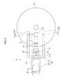
Fig. 1 is an overall perspective view of a hologram recorder according to an embodiment of the present invention. -
Fig. 2 is a front view of the hologram recorder inFig. 1 . -
Fig. 3 is a top view of the hologram recorder inFig. 1 . -
Fig. 4 is a side view of a constituent element included in the hologram recorder inFig. 1 . -
Fig. 5 is an explanatory diagram for describing an operation of the hologram recorder inFig. 1 . -
Fig. 6 is an explanatory diagram for describing an operation of the hologram recorder inFig. 1 . - Preferred embodiments of the present invention will be described below with reference to the accompanying drawings.
Fig. 1 through 6 show an embodiment of the hologram recorder according to the present invention. - A hologram recorder A in
Fig. 1 records holograms in a disc-shaped hologram recording medium B by means of an angular multiplex method. The hologram recorder A includes a recording-beam optical system for applying a recording beam Lw perpendicularly to a unit recording area B1 in the hologram recording medium B; a reference-beam optical system for applying a reference beam Lr to the unit recording area B1 at an angle; and a referencebeam swing mechanism 30. Unillustrated components include a beam source which generates a laser beam, and a beam splitter for splitting the laser beam into the recording beam Lw and the reference beam Lr. The recording-beam optical system is composed of aspatial light modulator 10, a reproduction beamseparation beam splitter 11, a first and asecond relay lenses separation beam splitter 14, and a recording-beamobjective lens 15. The reference-beam optical system include twofixed reflection members oblique appliers oblique appliers beam swing mechanism 30. The referencebeam swing mechanism 30 is composed of aU-shaped arm member 31 which is capable of swinging about a rotation axis defined along a radial direction of the hologram recording medium B, and adrive motor 32 which rotates thearm member 31 about the rotation axis. It should be noted here that the recording-beam and reference-beam optical systems as well as the referencebeam swing mechanism 30, etc. are mounted on a carrier head (not illustrated) which is movable radially of the hologram recording medium B. - The hologram recording medium B has a recording layer made of a photo polymer for example. The beams are applied from both of the upper and the lower sides of the recording layer per unit recording area B1. When recording, the recording beam Lw and the reference beam Lr are applied from above the unit recording area B1. The recording beam Lw enters vertically to the unit recording area B1 while the reference beam Lr enters obliquely to the recording beam, causing an interference. If the angle of the reference beam Lr with respect to the recording beam Lw is varied during this process, the interference stripe pattern is varied according to the angle, and these different patterns are recorded in multiplicity as page-by-page holograms. When reproducing, only the reference beam Lr is applied from below the unit recording area B1, whereby the unit recording area B1 gives off a reproduction beam Lp in the opposite direction as to the recording beam Lw (see
Fig. 5 andFig. 6 ). The reproduction beam Lp is detected by an unillustrated reproduction-purpose beam reception sensor so the information recorded in the form of hologram is reproduced. - The laser beam which comes out of the unillustrated beam source is converted into a parallel beam by an unillustrated collimator lens, and thereafter split by the beam splitter into the recording beam Lw and the reference beam Lr. The recording beam Lw travels to the
spatial light modulator 10 while the reference beam Lr travels to thefixed reflection member 20. - The
spatial light modulator 10, which is provided by a transparent liquid crystal device for example, modulates the incoming recording beam Lw into a beam which has a two-dimensional pixel pattern in accordance with the information to be recorded. The recording beam Lw which comes out of thespatial light modulator 10 passes through the reproduction beamseparation beam splitter 11, to therelay lenses relay lenses separation beam splitter 14, then passes through the recording-beamobjective lens 15, and finally hits the unit recording area B1 vertically in the hologram recording medium B. Thespatial light modulator 10 and the reproduction beamseparation beam splitter 11 are supported by an unillustrated support member. On the other hand, therelay lenses separation beam splitter 14, and the recording-beamobjective lens 15 are supported by an unillustrated lens holder which is a different member from the support member. The support member and the lens holder are disposed at a distance from each other, and the optical path of the recording beam Lw is in an uncovered state between the reproduction beamseparation beam splitter 11 and therelay lens 12. Specifically, thearm member 31 can move through the space between thebeam splitter 11 and therelay lens 12, across the optical path of the recording beam Lw. - The
fixed reflection members relay lens 12 and in front of thedrive motor 32, are suspended by the lens holder. It should be noted here that the lens holder is held by the carrier head via a frame (not illustrated) which detours thearm member 31. The reference beam Lr enters the reference beam reflection means 22 via these fixedreflection members - The reference beam reflection means 22 is disposed at an
axis base 31A which provides a center of rotation for thearm member 31. As shown inFig. 4 , the reference beam reflection means 22 includes afront panel 22A through which the reference beam Lr passes, aback panel 22B and arotating reflector 22C between the two panels. The reference beam Lr enters therotating reflector 22C from a predetermined direction. Therotating reflector 22C is pivotable around apivot shaft 22D in both directions. When therotating reflector 22C is pivoted counterclockwise as illustrated in solid lines in the figure for instance, therotating reflector 22C makes contact, on its two ends, withstoppers 22E which are disposed diagonally on the inner surfaces of thefront panel 22A and theback panel 22B. At this point, therotating reflector 22C becomes halted, being unable to pivot any further, and the reference beam Lr is reflected in a predetermined, obliquely upward direction. Thus, the reference beam Lr which is reflected by the reflection surface of therotating reflector 22C travels along this predetermined, obliquely upward direction of reflection, to afirst tip 31B of thearm member 31 which is positioned above the hologram recording medium B. On the contrary, when therotating reflector 22C is pivoted clockwise as illustrated in phantom lines in the figure, therotating reflector 22C makes contact, on its two ends, withstoppers 22F which are a different set of stoppers. At this point again, therotating reflector 22C becomes halted, being unable to pivot any further, and the reference beam Lr is reflected in a predetermined, obliquely downward direction. Thus, the reference beam Lr which is reflected by the reflection surface of therotating reflector 22C travels along this predetermined, obliquely downward direction of reflection, to asecond tip 31C of thearm member 31 which is positioned below the hologram recording medium B. - The reference
beam oblique appliers beam oblique applier 23A, is fixed to thefirst tip 31B of thearm member 31 which is positioned above the hologram recording medium B. This referencebeam oblique applier 23A works at the time of recording, by reflecting the reference beam Lr which comes from the reference beam reflection means 22, allowing the reference beam Lr to enter the unit recording area B1 from an obliquely upper direction. The other of the means, i.e. the referencebeam oblique applier 23B, is fixed to thesecond tip 31C of thearm member 31 which is positioned below the hologram recording medium B. This referencebeam oblique applier 23A works at the time of reproducing, by reflecting the reference beam Lr which comes from the reference beam reflection means 22, allowing the reference beam Lr to enter the unit recording area B1 from an obliquely lower direction. According to the referencebeam oblique appliers - The
axis base 31A of thearm member 31 is disposed substantially on a straight line along a radius of the hologram recording medium B. Theaxis base 31A is rotated by thedrive motor 32 about a rotation axis which lies radially of the hologram recording medium B. The rotation axis of thearm member 31 is perpendicular to the normal of incidence on the unit recording area B1. The normal of incidence is identical with the optical axis of the recording beam Lw which enters the unit recording area B1.
Thedrive motor 32 is provided by e.g. a supersonic motor which is capable of providing quick and accurate position control. Thefirst tip 31B of thearm member 31 is positioned as extended in parallel to the hologram recording medium B obliquely above the unit recording area B1, whereas thesecond tip 31C is positioned as extended in parallel to the hologram recording medium B obliquely below the unit recording area B1. As thearm member 31 rotates, thefirst tip 31B moves, as illustrated in solid lines and phantom lines inFig. 2 , from an obliquely upper right position to an obliquely upper left position, or vise versa, over the unit recording area B1. In this process, thesecond tip 31C moves from an obliquely lower left position to an obliquely lower right position of the unit recording area B1 since thesecond tip 31C is disposed in symmetry to thefirst tip 31B, with the center of symmetry being the unit recording area B1. - Specifically, at the time of recording, the
first tip 31B moves from an obliquely upper right position to an obliquely upper left position over the unit recording area B1, whereby the entering angle of the reference beam Lr, which makes an entry into the unit recording area B1 obliquely from the referencebeam oblique applier 23A of thefirst tip 31B, is varied within a range from e.g. about obliquely right 45 through 65 degrees as well as within a range from about obliquely left 45 through 65 degrees, by a predetermined increment angle. When reproducing, thesecond tip 31C moves from an obliquely lower left position to an obliquely lower right position of the unit recording area B1, whereby the entering angle of the reference beam Lr, which makes an entry into the unit recording area B1 obliquely from the referencebeam oblique applier 23B of thesecond tip 31C, is varied similarly as in recording, within a range from e.g. about obliquely left 45 through 65 degrees as well as within a range from about obliquely right 45 through 65 degrees, by the predetermined increment angle. It should be noted here that from a practical stand point, the entering angle of the reference beam Lr should preferably be varied within a range of about 50 through 60 degrees. The reference beam Lr in the reproducing operation is optically conjugate with the reference beam Lr in the recording operation. In the present embodiment, thefirst tip 31B and thesecond tip 31C make their travel around the unit recording area B1 at the same radius of revolution. However, there may be an arrangement, for example, that the rotation axis of the arm member is positioned below the hologram recording medium so that the two tips will have a different radius of revolution from each other. - Next, description will cover optical functions at the time of recording and at the time of reproducing.
- When recording, the recording beam Lw enters e.g. one unit recording area B1 vertically: The recording beam Lw is modulated by the spatial
light modulator 10 into a beam which has a two-dimensional pixel pattern unique to the information to be recorded. The reference beam Lr is reflected by the reference beam reflection means 22 to travel to thefirst tip 31B of thearm member 31, then is reflected by the referencebeam oblique applier 23A of thefirst tip 31B, and enters the unit recording area B1 to interfere with the recording beam Lw. - During this process, each time the recording beam Lw is modulated, the
first tip 31B of thearm member 31 is revolved in an intermittent manner by a predetermined angle, within a predetermined angle range defined e.g. obliquely above right of the unit recording area B1 (see the state indicated by solid lines inFig. 2 ). After this step, the tip is revolved quickly to an obliquely above left position over the unit recording area B1, and at this obliquely above left position again, is turned intermittently by a predetermined angle, within a predetermined angle range (see the state indicated by phantom lines inFig. 2 ). Thus, the reference beam Lr makes its entry into the unit recording area B1 from an obliquely upper right direction while changing its entering angle by a little increment, then makes its entry again into the unit recording area B1 from an obliquely upper left direction while changing its entering angle by a little increment, and at each occasion, the reference beam Lr makes an interfere with the recording beam Lw from a different direction and angle. As a result, page-by-page holograms are recorded in multiplicity in the unit recording area B1, over a predetermined number of pages. It should be noted here that reference beam Lr can become slightly out of alignment with respect to the unit recording area B1 depending on the entering angle of the reference beam Lr. However, the reference beam Lr is maintained accurately at the unit recording area B1 as the referencebeam oblique applier 23A, which is provided by a galvanomirror, performs fine adjustment on the reflection angle. - Now, assume that the
arm member 31 will be moved within an angle range of about 45 through 65 degrees in a stepped manner by a 5-degree increment, in the obliquely above right range as well as in the obliquely above left range over the unit recording area B1. Then, the reference beam Lr will take ten different patterns as a combination of the entering directions and the entering angles. Thus, one unit recording area B1 will have a multiplicity of ten, which means that there will be a multiplex recording of a ten-page amount of holograms. It should be noted here that the multiplicity can be further increased through an appropriate selection on the range of revolution and the step of angle. Once such a multiplex recording of holograms over a number of pages has been complete in one unit recording area B1 as described, then the same procedure may be repeated to another unit recording area to perform another cycle of the multiplex hologram recording. - At the time of reproducing when holograms are read page by page out of a recorded unit recording area B1, the recording beam Lw is blocked so that it will not enter the spatial
light modulator 10 for example. On the other hand, the reference beam Lr is introduced into thesecond tip 31C of thearm member 31 as therotating reflector 22C of the reference beam reflection means 22 is shifted to a predetermined pivotal position. Thus, the unit recording area B1 receives only the reference beam Lr which was reflected by the referencebeam oblique applier 23B of thesecond tip 31C, from obliquely below. - During this process, the
second tip 31C of thearm member 31 is revolved intermittently as is at the time of recording, by the predetermined angle within the predetermined angle range defined e.g. obliquely below left of the unit recording area B1 (see the state indicated by solid lines inFig. 6 ). After this step, the tip is revolved quickly to an obliquely below right position under the unit recording area B1, and at this obliquely below right position again, is revolved intermittently by the predetermined angle, within the predetermined angle range (see the state indicated by phantom lines inFig. 6 ). Thus, the reference beam Lr makes its entry into the unit recording area B1 from an obliquely lower left direction while changing its entering angle by a little increment, then makes its entry again from an obliquely lower right direction while changing its entering angle by a little increment - Again, at the time of reproducing, the reference beam Lr is maintained accurately at the unit recording area B1 as the reference
beam oblique applier 23B, which is provided by a galvanomirror, performs fine adjustment on the reflection angle. Further, according to the referencebeam oblique applier 23B, the reference beam Lr receives fine adjustment on its entering direction and entering angle so that they are identical with the direction and the angle at the time of the recording. It should be noted here that the entering direction of the reference beam Lr at the time of reproducing is the opposite of the direction from the time of recording. Thus, the reference beam Lr makes its entry into the unit recording area B1 in the opposite direction from what it did at the time of recording, making the entry from an obliquely lower left direction while changing its entering angle by a little increment, and then makes its entry again from an obliquely lower right direction while changing its entering angle by a little increment. - Now, assume, as did at the time of recording, that the
arm member 31 will be moved within an angle range of about 45 through 65 degrees in a stepped manner by a 5-degree increment while applying the reference beam Lr to the unit recording area B1. Then, in this unit recording area B1, the reproducing reference beam Lr will interfere with holograms which were recorded in multiplicity, page by page according to the direction and the entering angle at the time of the recording. As a result, the unit recording area B1 gives off a reproduction beam Lp page by page. The reproduction beam Lp travels in the opposite direction from what the recording beam Lw did, passing through theobject lens 15, thebeam splitter 14, then therelay lenses separation beam splitter 11 and finally, it is received by the unillustrated reproduction-purpose beam reception sensor, whereby the multiplexed record of holograms is reproduced page by page. - The hologram recorder A according to the present embodiment has a capability to apply the reference beam Lr to the unit recording area B1 from two, i.e. a right and a left, oblique directions while varying the entering angle, and therefore is capable of making multiplex recording of holograms at a higher multiplicity, about two times as compared to a case where the reference beam application is made only from one oblique direction, making it possible to easily increase the multiplicity.
- Mechanically, the recorder uses a simple construction that a
drive motor 32 rotates anarm member 31 about a predetermined rotation axis. In terms of optics, too, the recorder uses only simple optical parts for beam reflection, adjustment on the reflection angle, etc. Thus, the recorder can be small in size and simple in composition. - When recording or reproducing holograms page by page, the reference beam Lr entering direction and entering angle must be varied, and for this purpose the
arm member 31 must be pitched along its path, and swung in the right/left direction along its path. In this process, adrive motor 32 which is provided by a supersonic motor pitches and swings thearm member 31 quickly and accurately, whereas referencebeam oblique appliers - While recording, the
rotating reflector 22C of the reference beam reflection means 22 may be activated to quickly switch the direction of reflection from one to the other each time a page of holograms, for example, has been recorded. This arrangement makes it possible to apply the reference beam Lr to interfere with a freshly recorded hologram obliquely from below so as to see if the recording has been made successfully. In other words, the verification process can be performed easily.
Claims (6)
- A hologram recorder for recording holograms in a selected unit recording area of a hologram recording medium by interference between a recording beam applied vertically to the unit recording area and a reference beam applied obliquely to the unit recording area, the hologram recorder comprising:a reference beam oblique applier for application of the reference beam obliquely to the unit recording area by reflection; anda reference beam swing mechanism for supporting the reference beam oblique applier and for swinging the reference beam oblique applier about a predetermined rotation axis which is perpendicular to an entering direction of the recording beam that makes an entry into the unit recording area.
- The hologram recorder according to claim 1, wherein the reference beam swing mechanism includes: an arm member having an axis base positioned on the rotation axis and an arm extended from the axis base to hold a first tip at an obliquely upper location above the unit recording area, the first tip being provided with the reference beam oblique applier; and a drive motor for rotating the axis base of the arm member about the rotation axis.
- The hologram recorder according to claim 2, wherein the arm member is rotated within a predetermined range of rotation, thereby enabling the first tip to assume a position which is obliquely above on one side of the unit recording area and a position which is obliquely above on another side of the unit recording area.
- The hologram recorder according to claim 2 or 3, wherein the arm member further includes a second tip held oppositely to the first tip, with the unit recording area at a center in between, the second tip also being provided with another reference beam oblique applier for application of the reference beam obliquely to the unit recording area by reflection.
- The hologram recorder according to claim 4, wherein the axis base of the arm member is provided with reference beam reflection means for reflection of the reference beam, which comes along the rotation axis, selectively toward one of the reference beam oblique applier provided at the first tip and said another reference beam oblique applier provided at the second tip.
- The hologram recorder according to any one of claims 1 through 5, wherein the reference beam oblique applier includes a galvanomirror capable of variable control on a direction in which the reference beam travels.
Applications Claiming Priority (1)
| Application Number | Priority Date | Filing Date | Title |
|---|---|---|---|
| PCT/JP2006/302505 WO2007094042A1 (en) | 2006-02-14 | 2006-02-14 | Hologram recorder |
Publications (3)
| Publication Number | Publication Date |
|---|---|
| EP1986058A1 true EP1986058A1 (en) | 2008-10-29 |
| EP1986058A4 EP1986058A4 (en) | 2009-03-25 |
| EP1986058B1 EP1986058B1 (en) | 2010-03-31 |
Family
ID=38371238
Family Applications (1)
| Application Number | Title | Priority Date | Filing Date |
|---|---|---|---|
| EP06713646A Expired - Fee Related EP1986058B1 (en) | 2006-02-14 | 2006-02-14 | Hologram recorder |
Country Status (5)
| Country | Link |
|---|---|
| US (1) | US7719735B2 (en) |
| EP (1) | EP1986058B1 (en) |
| JP (1) | JPWO2007094042A1 (en) |
| DE (1) | DE602006013353D1 (en) |
| WO (1) | WO2007094042A1 (en) |
Families Citing this family (2)
| Publication number | Priority date | Publication date | Assignee | Title |
|---|---|---|---|---|
| JPWO2009044470A1 (en) * | 2007-10-04 | 2011-02-03 | 富士通株式会社 | Hologram reproducing apparatus and hologram reproducing method |
| WO2009075024A1 (en) * | 2007-12-11 | 2009-06-18 | Fujitsu Limited | Hologram recorder |
Citations (4)
| Publication number | Priority date | Publication date | Assignee | Title |
|---|---|---|---|---|
| US20030072045A1 (en) * | 2001-10-17 | 2003-04-17 | Brian King | System and method for holographic storage |
| WO2003091995A1 (en) * | 2002-04-26 | 2003-11-06 | Discovision Associates | Parallel recording and reading of diffractive memory using multiple object beams |
| EP1526545A1 (en) * | 2003-10-22 | 2005-04-27 | Daewoo Electronics Corporation | Angular multiplexing apparatus for holographic storage medium |
| WO2006000980A1 (en) * | 2004-06-24 | 2006-01-05 | Koninklijke Philips Electronics N.V. | Phase-conjugate read-out in a holographic data storage |
Family Cites Families (8)
| Publication number | Priority date | Publication date | Assignee | Title |
|---|---|---|---|---|
| US4018503A (en) * | 1973-02-01 | 1977-04-19 | Daniel Silverman | Holographic systems having reference beam coded holograms |
| US6330088B1 (en) * | 1998-02-27 | 2001-12-11 | Zebra Imaging, Inc. | Method and apparatus for recording one-step, full-color, full-parallax, holographic stereograms |
| US6157473A (en) | 1998-12-31 | 2000-12-05 | Daewoo Electronics Co., Ltd. | Holographic storage system incorporated therein a parabolic mirror |
| JP4347667B2 (en) * | 2003-11-12 | 2009-10-21 | Tdk株式会社 | Holographic memory reproducing method, holographic memory reproducing apparatus, and holographic recording / reproducing apparatus |
| JP4355607B2 (en) | 2004-04-15 | 2009-11-04 | Tdk株式会社 | Holographic recording method, holographic recording apparatus, holographic recording / reproducing method, holographic recording / reproducing apparatus, and holographic recording medium |
| US7333251B2 (en) * | 2004-06-08 | 2008-02-19 | Daewoo Electronics Corporation | Holographic data recording apparatus and method |
| JP2006023704A (en) * | 2004-06-09 | 2006-01-26 | Alps Electric Co Ltd | Hologram device |
| US20050275916A1 (en) | 2004-06-09 | 2005-12-15 | Alps Electric Co., Ltd. | Hologram device |
-
2006
- 2006-02-14 WO PCT/JP2006/302505 patent/WO2007094042A1/en active Application Filing
- 2006-02-14 DE DE602006013353T patent/DE602006013353D1/en active Active
- 2006-02-14 JP JP2008500359A patent/JPWO2007094042A1/en active Pending
- 2006-02-14 EP EP06713646A patent/EP1986058B1/en not_active Expired - Fee Related
-
2008
- 2008-08-13 US US12/190,873 patent/US7719735B2/en not_active Expired - Fee Related
Patent Citations (4)
| Publication number | Priority date | Publication date | Assignee | Title |
|---|---|---|---|---|
| US20030072045A1 (en) * | 2001-10-17 | 2003-04-17 | Brian King | System and method for holographic storage |
| WO2003091995A1 (en) * | 2002-04-26 | 2003-11-06 | Discovision Associates | Parallel recording and reading of diffractive memory using multiple object beams |
| EP1526545A1 (en) * | 2003-10-22 | 2005-04-27 | Daewoo Electronics Corporation | Angular multiplexing apparatus for holographic storage medium |
| WO2006000980A1 (en) * | 2004-06-24 | 2006-01-05 | Koninklijke Philips Electronics N.V. | Phase-conjugate read-out in a holographic data storage |
Non-Patent Citations (1)
| Title |
|---|
| See also references of WO2007094042A1 * |
Also Published As
| Publication number | Publication date |
|---|---|
| DE602006013353D1 (en) | 2010-05-12 |
| EP1986058A4 (en) | 2009-03-25 |
| WO2007094042A1 (en) | 2007-08-23 |
| JPWO2007094042A1 (en) | 2009-07-02 |
| US7719735B2 (en) | 2010-05-18 |
| US20080304122A1 (en) | 2008-12-11 |
| EP1986058B1 (en) | 2010-03-31 |
Similar Documents
| Publication | Publication Date | Title |
|---|---|---|
| US6490061B1 (en) | Optical information recording and reproducing apparatus having volume holographic memory | |
| US7859973B2 (en) | Method for recording and reproducing a hologram and apparatus therefor | |
| US6320683B1 (en) | Optical information recording and reproducing apparatus using a volume holographic memory | |
| JP2006517304A5 (en) | ||
| JP6667177B2 (en) | Hologram recording / reproducing method and hologram recording / reproducing apparatus | |
| US7719735B2 (en) | Hologram recorder | |
| JP4351551B2 (en) | Holographic recording method, holographic recording apparatus, holographic recording medium, holographic memory reproducing method and apparatus | |
| US7085217B2 (en) | Apparatus and method for recording optical information, apparatus and method for reproducing optical information, and apparatus and method for recording/reproducing optical information | |
| JP2005122867A (en) | Holographic optical information recorder by objective lens having two focal points in which optical axes of information light and reference light for recording are not separated from each other | |
| US6504810B2 (en) | Optical information recording/reproducing system | |
| US7385741B2 (en) | Holographic recording system and optical chopper | |
| US7751105B2 (en) | Hologram recording apparatus and hologram recording/reproducing method | |
| WO2004013705A1 (en) | Hologram recording/reproducing system | |
| JPH11119124A (en) | Control system of composite incident beam | |
| JP4738935B2 (en) | Hologram recording method and hologram recording apparatus | |
| EP1494221B1 (en) | Holographic ROM system including an alignment apparatus for aligning a holographic medium and a mask | |
| CN100472615C (en) | Apparatus and method for recording and reproducing optical information | |
| CN103456326B (en) | Hologram optical take-up apparatus, optical information recording/reproducing device and method | |
| CN101681634A (en) | Holographic recording/reproducing apparatus | |
| KR100571840B1 (en) | An apparatus for recording/reproducing holographic information | |
| JP4927165B2 (en) | Hologram device | |
| KR100277945B1 (en) | Holographic recording / playback method | |
| CN216362047U (en) | Recording and reproducing apparatus for increasing hologram recording speed in cross-shift multiplexing | |
| JPS6034100Y2 (en) | Optical information recording and reproducing device | |
| JPH03160692A (en) | Hologram storage device |
Legal Events
| Date | Code | Title | Description |
|---|---|---|---|
| PUAI | Public reference made under article 153(3) epc to a published international application that has entered the european phase |
Free format text: ORIGINAL CODE: 0009012 |
|
| 17P | Request for examination filed |
Effective date: 20080815 |
|
| AK | Designated contracting states |
Kind code of ref document: A1 Designated state(s): DE FR GB |
|
| DAX | Request for extension of the european patent (deleted) | ||
| RBV | Designated contracting states (corrected) |
Designated state(s): DE FR GB |
|
| A4 | Supplementary search report drawn up and despatched |
Effective date: 20090220 |
|
| GRAP | Despatch of communication of intention to grant a patent |
Free format text: ORIGINAL CODE: EPIDOSNIGR1 |
|
| GRAS | Grant fee paid |
Free format text: ORIGINAL CODE: EPIDOSNIGR3 |
|
| GRAA | (expected) grant |
Free format text: ORIGINAL CODE: 0009210 |
|
| AK | Designated contracting states |
Kind code of ref document: B1 Designated state(s): DE FR GB |
|
| REG | Reference to a national code |
Ref country code: GB Ref legal event code: FG4D |
|
| REF | Corresponds to: |
Ref document number: 602006013353 Country of ref document: DE Date of ref document: 20100512 Kind code of ref document: P |
|
| PGFP | Annual fee paid to national office [announced via postgrant information from national office to epo] |
Ref country code: FR Payment date: 20101229 Year of fee payment: 6 |
|
| PLBE | No opposition filed within time limit |
Free format text: ORIGINAL CODE: 0009261 |
|
| STAA | Information on the status of an ep patent application or granted ep patent |
Free format text: STATUS: NO OPPOSITION FILED WITHIN TIME LIMIT |
|
| 26N | No opposition filed |
Effective date: 20110104 |
|
| PGFP | Annual fee paid to national office [announced via postgrant information from national office to epo] |
Ref country code: DE Payment date: 20110308 Year of fee payment: 6 |
|
| PGFP | Annual fee paid to national office [announced via postgrant information from national office to epo] |
Ref country code: GB Payment date: 20110224 Year of fee payment: 6 |
|
| GBPC | Gb: european patent ceased through non-payment of renewal fee |
Effective date: 20120214 |
|
| REG | Reference to a national code |
Ref country code: FR Ref legal event code: ST Effective date: 20121031 |
|
| REG | Reference to a national code |
Ref country code: DE Ref legal event code: R119 Ref document number: 602006013353 Country of ref document: DE Effective date: 20120901 |
|
| PG25 | Lapsed in a contracting state [announced via postgrant information from national office to epo] |
Ref country code: GB Free format text: LAPSE BECAUSE OF NON-PAYMENT OF DUE FEES Effective date: 20120214 Ref country code: FR Free format text: LAPSE BECAUSE OF NON-PAYMENT OF DUE FEES Effective date: 20120229 |
|
| PG25 | Lapsed in a contracting state [announced via postgrant information from national office to epo] |
Ref country code: DE Free format text: LAPSE BECAUSE OF NON-PAYMENT OF DUE FEES Effective date: 20120901 |