EP1985989A1 - Breaking prediction method - Google Patents
Breaking prediction method Download PDFInfo
- Publication number
- EP1985989A1 EP1985989A1 EP07707897A EP07707897A EP1985989A1 EP 1985989 A1 EP1985989 A1 EP 1985989A1 EP 07707897 A EP07707897 A EP 07707897A EP 07707897 A EP07707897 A EP 07707897A EP 1985989 A1 EP1985989 A1 EP 1985989A1
- Authority
- EP
- European Patent Office
- Prior art keywords
- fracture
- strain
- stress
- space
- prediction method
- Prior art date
- Legal status (The legal status is an assumption and is not a legal conclusion. Google has not performed a legal analysis and makes no representation as to the accuracy of the status listed.)
- Granted
Links
Images









Classifications
-
- G—PHYSICS
- G01—MEASURING; TESTING
- G01N—INVESTIGATING OR ANALYSING MATERIALS BY DETERMINING THEIR CHEMICAL OR PHYSICAL PROPERTIES
- G01N3/00—Investigating strength properties of solid materials by application of mechanical stress
-
- B—PERFORMING OPERATIONS; TRANSPORTING
- B05—SPRAYING OR ATOMISING IN GENERAL; APPLYING FLUENT MATERIALS TO SURFACES, IN GENERAL
- B05D—PROCESSES FOR APPLYING FLUENT MATERIALS TO SURFACES, IN GENERAL
- B05D5/00—Processes for applying liquids or other fluent materials to surfaces to obtain special surface effects, finishes or structures
- B05D5/12—Processes for applying liquids or other fluent materials to surfaces to obtain special surface effects, finishes or structures to obtain a coating with specific electrical properties
-
- G—PHYSICS
- G06—COMPUTING OR CALCULATING; COUNTING
- G06F—ELECTRIC DIGITAL DATA PROCESSING
- G06F30/00—Computer-aided design [CAD]
- G06F30/10—Geometric CAD
- G06F30/15—Vehicle, aircraft or watercraft design
-
- G—PHYSICS
- G06—COMPUTING OR CALCULATING; COUNTING
- G06F—ELECTRIC DIGITAL DATA PROCESSING
- G06F30/00—Computer-aided design [CAD]
- G06F30/20—Design optimisation, verification or simulation
- G06F30/23—Design optimisation, verification or simulation using finite element methods [FEM] or finite difference methods [FDM]
-
- G—PHYSICS
- G01—MEASURING; TESTING
- G01N—INVESTIGATING OR ANALYSING MATERIALS BY DETERMINING THEIR CHEMICAL OR PHYSICAL PROPERTIES
- G01N2203/00—Investigating strength properties of solid materials by application of mechanical stress
- G01N2203/0058—Kind of property studied
- G01N2203/006—Crack, flaws, fracture or rupture
Definitions
- the present invention relates to a fracture prediction method and a device as well as a program product and a recording medium for a thin plate formed of a metal material, and is particularly preferable as a fracture determining criterion for a material fracture in a crash process of an automobile member subjected to press-forming.
- the margin against a fracture is determined in general using a thinning criterion or a forming limit diagram (FLD).
- the FLD indicates the major and minor strain ( ⁇ 1 and ⁇ 2 , respectively) at which the failure occurs, and can be used in a crash analysis.
- the FLD can be experimentally determined by loading specimens along various proportional paths. Nakazima et al., for instance, operated hemispherical punch stretching for rectangular specimens with various widths. Before the forming operation, small circulars or grids are marked on the sheet surface by etching or printing. Theses circles are distorted into ellipses during the forming operation, which will be terminated at the onset of necking or crack.
- the size of an ellipse near the neck varies with the width of the specimen.
- the major and minor strains are measured from the ellipse at the neck or crack.
- the forming limit curve (FLC) is drawn so that it fits the measured limit strains for various paths.
- Fig. 1 shows a fracture limit curve measured by experiment.
- the FLD As an FLD prediction method, there are combined usage of Hill's criterion and Swift's one, Marciniak-Kuczynski model, Storen-Rice model, and the like, and the FLD can be obtained by correcting the influence of a sheet thickness by a Keeler's empirical rule.
- the tearing can be produced by a dynamic FE code, whereas the former cannot be detected in the FE analyses. Instead of direct predictions of the tearing, the computed strains are compared with critical values external prepared and it is regarded that the failure occurs when one of the computed strains reaches the limit.
- Non-patent Document 1 Journal of the Japan Society for Technology of Plasticity, 45, 123, 2004
- the strain path In a car crash deformation process of an automobile body part subjected to press-forming or pre-deformation in press-forming, the strain path often changes.
- forming limits strains When evaluating a fracture using the forming limit strains obtained by experiment, forming limits strains must be prepared according to the an infinite number of strain paths. Therefore, in practice, the forming limit strain with respect to a proportional loading path needs to be used for evaluation of a fracture, and hence high prediction accuracy cannot be expected.
- steel sheets failure occurs under stretch-flanging when a stretch strain in the circumferential direction of a cutting edge reaches the critical value.
- the stress state in the cutting edge portion is close to the uniaxial tension, but abrupt gradients of stress and strain exist inward from the cutting edge portion.
- the fracture limit indicates a value that is quite different compared to the fracture limit strain or stress obtained by a uniaxial tensile test.
- high-strength steels over 590MPa suffer from the breakage under stretch-flanging, even when the cutting edge portion reaches a plastic instability and localized necking (thickness necking) occurs, the inside material excluding the cutting edge portion has not satisfied the plastic instability yet.
- the plastic instability cannot be reached as the whole, and progress of the localized necking is delayed.
- a large number of thickness necks are formed in a circumferential direction of the cutting edge portion, and thus the fracture is delayed.
- a localized necking is formed at one position in the cutting edge portion, stress in the circumferential direction in the vicinity of the localized necking is eased.
- the influence of this ease of stress decreases with distance from the localized necking, and when the deformation proceeds further, a next localized necking is formed at a separated location from the first localized necking.
- a new neck is formed. Repeating this process, a large number of thickness necks are formed in the circumferential direction of the cutting edge portion, and the localized necking grow.
- the prediction method for the stretch-flanging limit is not easy due to existence of the strain gradient inward from the cutting edge portion, and to a delay effect such that a fracture does not occur even when one position in the circumferential direction satisfies the localized necking. Thus, such a method is not proposed hitherto.
- the present invention is directed to solving the above-described problems of conventional arts as technical problems, and an object thereof is to provide a fracture prediction method by which, when predicting presence of fracture occurrence in a steel sheet in a process including one or more strain paths , the fracture limit curve can be obtained easily and efficiently and presence of fracture occurrence can be predicted with high prediction accuracy, and the risk of fracture upon press forming or crashworthiness can be evaluated quantitatively, thereby realizing efficient and highly precise development of autobodies optimizing the material, the forming , and the car body structures for crash safety .
- a fracture prediction method of the present invention is a method evaluating a fracture limit of a thin plate constituted of a metal material, and the method includes, when predicting fracture occurrence in the thin plate in a plastic deformation process according to one or more deformation path changes, a procedure of converting a fracture limit curve in strain space into a fracture limit curve in stress space, and a procedure of predicting presence of the fracture occurrence using the obtained fracture limit curve in stress space.
- a fracture limit obtaining method of the present invention is a method of obtaining a fracture limit used for determining a fracture limit of a thin plate constituted of a metal material, in which a stretch strain ratio ⁇ obtained from a hole expansion test is converted into a fracture limit curve in stress space when determining a fracture limit of the thin plate in a process including one or more deformation path variations.
- the fracture limit curve expressed in stress space does not depend on a deformation path, and hence can be expressed by a single limit curve. Therefore, using this as a fracture determining criterion, a fracture in a stretch flange portion including one or more deformation path variations can be determined with high accuracy.
- the present invention when predicting presence of fracture occurrence in a thin plate in a process including one or more deformation path variations, it is possible to obtain the fracture limit curve easily and efficiently and predict the presence of fracture occurrence with high prediction accuracy.
- the risk of fracture upon press forming or crash can be evaluated quantitatively, thereby realizing efficient and highly precise development of an automobile body considering the material, the construction method, and the structure at the same time.
- the margin against a fracture when evaluating formability is determined in general using a thinning criterion or an FLD, which can be used for fracture prediction in a car crash analysis as well.
- the FLD is known to vary largely depending on a strain path changes, and cannot be expected to have high prediction accuracy as a method of evaluating a fracture in a plastic deformation process, in which the deformation path varies largely as in crash of an automobile body part subjected to press-forming or pre-deformation in press-forming.
- Non-patent documents 1, 2 verified by experiment and analysis that, using a fracture limit curve expressed in stress space with an aluminum extruded material or mild steel sheets being the subject, the fracture limit can be represented almost uniquely without depending on the path of deformation.
- This knowledge relates to aluminum or mild steel sheets and is not clarified for high strength steels over 440 MPa, and hence cannot be used for current development of an automobile body in which high-strength steel sheets are mainly used.
- t represents the thickness of a thin plate
- YP proof strength
- TS ultimate tensile strength
- U.E1 uniform elongation
- El represents total elongation
- a fracture strain was measured with a scribed circle diameter being 6 mm by a uniaxial tension, a Nakajima method ( hemispherical punch stretching using a Teflon (registered trademark) sheet), and a hydraulic bulge test.
- a fracture strain was measured by the uniaxial tension and the Nakajima method so that the direction of 90° degrees from the primary extension direction is the maximum principal stress.
- the high-degree polynomial expression of an equivalent plastic strain or another form may be used, but it is preferable to use the Swift's equation, which is highly precise in approximation and is used frequently in a numerical simulation of a thin steel sheet.
- a high-degree anisotropic yield function may be used as necessary, but it has many parameters and requires considering the direction in a plate surface while processing, and hence provides insufficient improvement in precision even though it is complicated.
- the yield function assuming planar isotropy is sufficient.
- the equivalent plastic stress ⁇ eq considering a deformation path variation can be obtained using the equivalent plastic strain ⁇ eq obtained by integrating an equivalent plastic strain increment d ⁇ eq on a strain path and the work-hardening law.
- x i represents x 1 axis//RD, x 2 axis//TD, x 3 axis//ND which coordinate axes of a material coordinate system, and X i represents the main axis of the strain in an n-th order deformation.
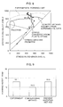
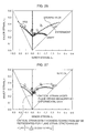
- Fig. 5 shows an FLD measured by experiment, and a fracture limit curve obtained by converting the FLD into stress space with a major stress and a minor stress by the aforementioned method.
- the FLD of strain space depends on the deformation path and the fracture limit curve varies largely, but the fracture limit curve expressed in stress space becomes a single fracture limit curve.
- a fracture limit curve obtained by converting an FLD measured by an experimental method other than the Nakajima method into stress space may be used, or a fracture limit curve obtained by converting a theoretical FLD of Hill's localized necking model, Swift's diffuse necking model, Marciniak-Kuczynski method, Storen-Rice model, or the like into stress space may be used for the fracture prediction.
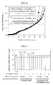
- Fig. 6 shows a relationship of a maximum major strain introduced by punch-stroke and press-forming.
- the influences of the element size and the material constitutive equation barely appear from the beginning of the formation to the punch-stroke of approximately 25 mm, but these influences become obvious beyond 25 mm where localization of the strain begins.
- Fig. 7 shows comparison of prediction accuracy when performing the numerical simulation with various analysis conditions and using an FLD obtained by experiment and a localized necking occurrence limit as a fracture determining criterion.
- the fracture determining criterion When the actually measured FLD is used as the fracture determining criterion, the localization process of a strain cannot be simulated precisely, and thus the accuracy of fracture prediction is not high.
- the localized necking occurrence limit is used as the fracture limit, prediction with relatively high accuracy becomes possible regardless of the element size and the used material constitutive equation, and evaluation on the safe side can be obtained.
- the localized necking occurrence limit may be used as the fracture determining criterion in practice because a ductile fracture in a steel sheet occurs at a position where deformation is localized by localized necking, and when localized necking occurs it leads to a fracture by very short time.
- the localized necking occurrence limit can be handled within the framework of plastic instability, and can be predicted by a theoretical FLD of Hill's localized necking model, Swift's diffuse necking model, Marciniak-Kuczynski method, Storen-Rice model, or the like.
- the present inventors have found that high prediction accuracy can be assured by using as the fracture determining criterion the fracture limit curve obtained by converting a necking start curve in strain space into stress space when evaluating a fracture by the numerical analysis simulation using the finite element method.
- a case example of the method of evaluating a fracture limit will be explained.
- a case example of fracture prediction on a non-linear path such that with the steel sheets shown in Table 1 being the subjects, an uniaxial tension of 10% in the rolling direction is performed as first deformation, and thereafter plane strain deformation is performed by hemispherical punch stretching .
- Fig. 8 shows a relationship between a stress history in a formation process obtained by a numerical simulation and a fracture limit curve obtained by converting a necking start curve in strain space into stress space.
- the obtained stress increases while vibrating largely because propagation of a stress wave is solved at minute time intervals without performing repetitive calculation within a time step.
- this method of comparing a positional relationship between a stress and a fracture limit stress to evaluate a fracture it is difficult to assure high prediction accuracy.
- the present inventors have devised a method of determining a fracture with high accuracy, which can avoid, when using the dynamic explicit method for the numerical simulation, vibration of a stress by converting a plastic strain into a stress by post-processing.
- Fig. 9 shows results of predicting a fracture with the present invention method.
- a conventional fracture prediction method by means of FLD prediction with high accuracy is difficult since the fracture limit curve varies largely depending on a deformation path.
- the present invention it can be seen that a fracture can be predicted with good accuracy even when the deformation path varies.
- the present invention is also able to evaluate a fracture by comparing a positional relationship between a value obtained by converting an experimental strain measurement result into a stress and a fracture limit curve, instead of performing the numerical simulation using the finite element method.
- the fracture prediction method of the present invention is applied in a three-point bending crash analysis of a member shown in Fig. 10 with a hat cross-section and a length of 900 mm.
- a finite element model for a crash analysis is created, on which spot-welding processing with a flat plate (with a relative displacement between two contact points being fixed) at 30 mm intervals is performed at a flange portion.
- the obtained forming analysis result is reflected on this finite element model for a crash analysis, and the crash analysis is performed by the numerical simulation by the dynamic explicit code.
- the deformation history during formation can be considered by inheriting a thinning and an equivalent plastic strain obtained by the numerical simulation of press-forming, or a thinning and an equivalent plastic strain, a stress tensor, a strain tensor as initial conditions of the crash analysis.
- the deformation history during formation can be considered by measuring a thickness of a press-formed product and an equivalent plastic strain by an experiment instead of the numerical simulation and inheriting one of them as an initial condition of the crash analysis.
- Fig. 12 shows a relationship between an equivalent plastic strain and an equivalent stress according to a strain rate
- Fig. 13 shows a positional relationship between a dynamic fracture stress limit curve in stress space and a dynamic stress obtained from a crash simulation.
- the present inventors have found that the stress at a reference strain speed obtained by converting a plastic strain obtained from the crash simulation may be used, and only the fracture stress limit curve at the single reference strain rate may be used as the fracture limit (fracture criterion) used for fracture determination.
- the reference strain rate may be a quasi-static strain rate.
- the range of the quasi-static strain rate differs depending on the material, the fracture limit curve measured in the range of 0.001/s to 1/s may be used in practice.
- Fig. 14 shows a result of predicting a fracture with the method of the present invention.
- a conventional fracture prediction method by means of FLD it is difficult to predict with high accuracy a plastic deformation process in which a deformation path varies largely as in a crash phenomenon after subjected to pre-deformation in press-forming.
- a fracture can be predicted with good accuracy even in a crash process after press-forming.
- a risk of fracture can be evaluated quantitatively from data obtained by simulating press-forming and crash processes of a steel sheet by a finite element method.
- the Cowper-Symonds equation is used as a representative example as the strain rate dependency of a deformation stress, but the effectiveness of the present invention does not change even using an arbitrary constitutive equation, for example an m-th power hardening equation, a Johnson-Cook equation, or the like, with which the strain rate dependency can be considered.
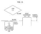
- the steel sheet was sheared by the size of 200 mm ⁇ 200 mm, and a hole with a diameter of 25 mm was punched through a center portion using a punch and a die.
- This steel sheet with a hole in the center was subjected to formation (Teflon sheet lubrication) with a flat-bottom punch with a diameter of 100 mm and a die shoulder R of 15 mm until a fracture occurs at a hole edge, and the hole diameter and the forming limit height when the fracture occurred were measured.
- the overview of the experiment is shown in Fig. 15 .
- the FLD was measured by the Nakajima method (hemispherical punch stretching using a Teflon sheet) for use as the criterion for fracture prediction in the numerical simulation.
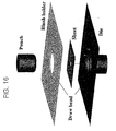
- the numerical simulation by the dynamic explicit FE code was performed to verify the prediction accuracy of a stretch-flanging limit that fractures from cutting edge.
- the material parameters provided for the numerical simulation are the ones used for the experiment, and the tools comply with those of the experiment.
- An analysis model is shown in Fig. 16 .
- the element size of 2 mm is used, which is equal to the distance between evaluation points when measuring the FLD, and a Hill's anisotropic yield function is used as the yield function for consideration.
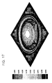
- Fig. 17 shows simulation results of the stretch-flanging forming by the cylindrical flat-bottom punch
- Fig. 18 shows a relationship between the distance from the hole edge and the major strain. From them, it can be seen that a large strain is introduced to the hole edge of the cutting edge and that a large strain gradient exists inward from the edge hole.
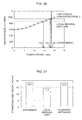
- Fig. 19 shows a relationship between a stress history, in which a plastic strain obtained from the numerical simulation is converted into stress space and plotted for every forming height, and a "necking occurrence limit stress curve" obtained by converting into stress space a "necking occurrence limit curve", which is obtained by offsetting a forming limit curve measured on a proportional loading path so that the limit value in a plane strain becomes equal to n value.
- the stress at the hole edge reaches the necking occurrence limit stress curve at the forming height of 14 mm, which differs largely from the forming limit height of 18.5 mm measured actually by experiment.
- the fracture was evaluated in stress space with the fracture criterion being set to the hole expansion ratio.
- d is the hole diameter (mm) when the fracture occurs
- do is the hole diameter (mm) of the steel sheet.
- Figs. 20, 21 shows results of predicting a fracture by the present invention method.
- a conventional "necking occurrence limit stress urgie" is used as the fracture criterion in a stretch - flanging forming
- the forming limit height is estimated low due to presence of a strain gradient inward from a cutting edge and a delay effect such that one position in the circumferential direction does not fracture when it satisfies the localized necking.
- the use of the criterion obtained by converting the hole expansion ratio into stress space for fracture determination allows to predict the fracture with good accuracy.
- Fig. 22 is a block diagram showing a main structure of a fracture prediction device according to this example.
- This fracture prediction device is for predicting presence of fracture occurrence in a steel sheet in a process including one or more deformation path variations regarding a steel sheet constituted of a metal material, and is structured including an estimating unit 21 estimating a fracture limit curve in strain space on a proportional loading path, a converting unit 22 converting the fracture limit curve in strain space obtained on the proportional loading path into a fracture limit curve in stress space, a fracture determining unit 23 determining presence of fracture occurrence with the fracture limit curve in stress space, and a display unit 24 displaying a determination result by the fracture determining unit 23, or the like.
- the estimating unit 21 identifies the material parameter Kc based on one or more measurement values of maximum fracture limit strain ⁇ 1 and minimum fracture limit strain ⁇ 2 .
- the fracture limit curve in strain space is estimated theoretically using the estimating unit 21 is exemplified, but the fracture limit curve in strain space may be measured experimentally without using the estimating unit 21.
- the fracture limit curve in strain space can be obtained, after a plurality of in-plane strain ratios regarding a thin plate are obtained by a proportional loading experiment, using measurement values of maximum fracture limit strain ⁇ 1 and minimum fracture limit strain ⁇ 2 in each of the strain ratios.
- the fracture determining unit 23 performs evaluation by comparing the positional relationship between the fracture limit curve in stress space converted by the converting unit 21 and the strain state of each portion obtained from results of the simulation by the finite element method in a plastic deformation process, and determines that it is a fracture or that the risk of fracture is high when the strain in the deformation process reaches this limit strain.
- the dynamic explicit method is used, which is one of finite element methods. In this case, the plastic strain obtained by the dynamic explicit method is converted into a stress and is compared with the fracture limit curve in stress space.
- the fracture determining unit 23 may also be configured to convert a strain obtained from deformation conditions of a thin plate evaluated by experiment into a stress and evaluate quantitatively presence of fracture occurrence using the fracture limit curve in stress space, instead of performing the aforementioned simulation.
- the fracture determining unit 23 executes a numerical analysis considering the speed dependency of a flow stress in the thin plate, converts the plastic strain obtained from the numerical analysis to calculate the stress at the reference strain speed, and compares this stress with the fracture limit curve in stress space corresponding to the reference strain rate .
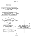
- Fig. 23 is a flowchart showing steps when performing fracture prediction in a forming process of a thin plate constituted of a metal material, with the fracture prediction method according to this example.
- the estimating unit 21 estimates a fracture limit curve in strain space on a proportional loading path (step S1).
- the converting unit 22 converts the fracture limit curve in strain space measured experimentally into a fracture limit curve in stress space using the Mises' yield function, so as to create a stress FLD (step S2).
- the fracture determining unit 23 performs evaluation by comparing the positional relationship between the fracture limit curve in stress space converted by the converting unit 21 and the strain state of each portion obtained from results of the simulation by the finite element method (here, the dynamic explicit method) in a plastic deformation process, and determines a fracture or the risk of fracture (step S3).
- step S3 when it is determined that the limit strain is reached and a fracture occurs in the thin plate or that the risk of fracture is high, the fracture determining unit 23 executes the following several processing (step S4).
- the element ID, the thickness of the thin plate, the strain, and the stress information are outputted to a log file. Further, the element that has reached the criterion is erased, and the analysis after the fracture is continued.
- step S5 The risk that a fracture occurs in the thin plate is contour displayed by a scalar amount. Further, the stress history of the fracture risk portion in stress space and the criterion are displayed. The risk of occurrence of a crease in the thin plate is contour displayed together. Here, the risk of fracture may be displayed with respect to dispersion (average value, lower limit value) within the standard of shipment test values.
- step S3 when it is determined in step S3 that there is no possibility of occurrence of a fracture or that the risk thereof is low, an indication about this is displayed on the display unit 24 in step S6.
- Fig. 24 is a flowchart showing steps when performing the fracture prediction in the crash process, continued from the fracture prediction in the formation step of Fig. 23 , with the fracture prediction method according to this example.
- the stress FLD created in step S2 of Fig. 23 is inherited and used.
- the fracture determining unit 23 executes a numerical analysis considering the strain rate dependency of a deformation stress in the thin plate, converts the plastic strain obtained from the numerical analysis to calculate the stress at the reference strain rate, and compares this stress with the fracture limit curve in stress space corresponding to the reference strain rate, thereby determining a fracture or the risk of fracture (step S11).
- the fracture determining unit 23 inherits deformation conditions of the thin plate evaluated by the numerical analysis in the formation process of Fig. 23 as an initial condition of the numerical analysis in the crash process.
- the deformation conditions are thinning and an equivalent plastic strain or thinning, an equivalent plastic strain, a stress tensor and a strain tensor.
- step S11 when it is determined that a fracture occurs in the thin plate or that the risk of fracture is high, the fracture determining unit 23 executes the following several processing (step S12).
- the element ID, thinning, the strain, and the stress information are outputted to a log file. Further, the element that has reached the criterion is erased, and the analysis after the fracture is continued.
- the risk that a fracture occurs in the thin plate is contour displayed by a scalar amount. Further, the stress history of the fracture risk portion in stress space and the criterion are displayed. The risk of occurrence of a crease in the thin plate is contour displayed together.
- the risk of fracture may be displayed with respect to dispersion (average value, lower limit value) within the standard of shipment test values.
- step S11 when it is determined in step S11 that there is no possibility of occurrence of a fracture in the thin plate or that the risk thereof is low, an indication about this is displayed on the display unit 24 in step S14.
- the margin against a fracture is often evaluated by a thinning, but due to popularization of numerical simulations and advancement in functions of post-processing software, fracture evaluation methods using a forming limit diagram (FLD) are started to be used widely.
- FLD forming limit diagram
- the FLD can be obtained by an experiment such as the Nakajima method.
- such a method is complicated, and it is difficult to construct a database for various types of steel sheet menus and thickness.
- several prediction approaches have been proposed.
- Non-patent document 1 For example, in post-processing functions of general-purpose software, there is incorporated a method (refer to Non-patent document 1) in which a Keeler's thickness correction empirical rule is added to the Hill's localized necking model and the Swift's diffuse necking model.
- a Keeler's thickness correction empirical rule is added to the Hill's localized necking model and the Swift's diffuse necking model.
- prediction values obtained with these theories allow to predict for aluminum or mild steel with relatively high accuracy, but for steel sheets with tensile strength of 440 MPa class or higher, they are overestimated on the uniaxial tension side and underestimated on the equi-biaxial stretching side. Thus, they are not suitable for current development of an automobile body in which high-strength steel sheets are mainly used.
- the FLD is known to vary largely depending on a deformation path.
- High prediction accuracy cannot be expected therefrom as a method of evaluating a fracture in a plastic deformation process, in which the deformation path varies largely as in crash of an automobile body part subjected to press-forming or pre-deformation in press-forming.
- recently Kuwabara et al. (refer to Non-patent documents 1, 2) verified by experiment and analysis that, using a fracture limit curve expressed in stress space with an aluminum extruded material or mild steel being the subject, the fracture limit can be represented almost uniquely without depending on the path of deformation. This knowledge relates to aluminum or mild steel and is not clarified for steel sheets with tensile strength of 440 MPa class or higher.
- the present inventors conducted detailed experiments on high strength steels with tensile strength of 440 MPa or higher, and have reached the following items for the first time.
- the fracture limit strain is measured by a proportional loading experiment with a steel sheet constituted of a metal material having mechanical property values and material parameters shown in Table 1 below being the subject.
- t represents the thickness of a thin plate
- YP proof strength
- TS represents ultimate tensile strength
- U.El uniform elongation
- El represents total elongation
- a fracture strain was measured with a scribed circle diameter being 6 mm by a uniaxial tension, the Nakajima method (ball head extrusion using a Teflon (registered trademark) sheet), and a hydraulic bulge test.
- Fig. 25 shows the FLD including the fracture limit curve in strain space measured by the above experiment.
- ⁇ eq C ⁇ ⁇ eq n
- the Swift's diffuse necking has a tendency to estimate the fracture limit small in the vicinity of the equi-biaxial stretching, and is needed to be improved. Therefore, it is more preferable to use the Storen-Rice model which is extended from the Hill's localized necking model based on the bifurcation theory.
- Fig. 26 shows the FLD including the fracture limit curve in strain space calculated using the Storen-Rice model.
- Ito et al. (refer to Non-patent document 4) proposed a constitutive equation in which the direction of a plastic strain increment tensor depends on a stress increment tensor, so as to overcome a drawback such that in the normality rule with the Mises' isotropic yield function being a plastic potential, the stress increment tensor and the plastic strain increment tensor do not correspond one to one, and the plastic strain increment direction does not follow a rapid variation in the stress direction.
- the parameter Kc defining the stress increment dependency of the plastic strain increment is necessary, but the physical background of Kc is unclear, and a deriving method of the parameter is not proposed.
- Fig. 27 shows an FLD calculated by obtaining Kc for the precipitation strengthened steel sheet of 590 MPa class shown in Table 5 by the above-described method and using a stress increment dependency law based on the Storen-Rice model. Note that, as a matter of course, it is possible to assure higher prediction accuracy by correction using the fracture limit strain ⁇ 1 * in a plane strain measured by experiment instead of the Keeler's thickness correction rule. However, in an aspect that the FLD database for various types of steel sheet menus and thickness can be constructed only by stress-strain curves by uniaxial tensile tests of materials, it is efficient to use the Keeler's thickness correction rule.
- the high-degree polynomial expression of an equivalent plastic strain or another form may be used, but it is preferable to use the Swift's equation, which is highly precise in approximation and is used frequently in a numerical simulation of a thin steel sheet.
- a high-degree anisotropic yield function may be used as necessary, but it has many parameters and requires considering the direction in a plate surface while processing, and hence provides insufficient improvement in precision even though it is complicated.
- the yield function assuming planer isotropy is sufficient.
- Fig. 29 shows results of conversion of the FLD predicted by the above-described method and the fracture limit strain under the deformation path variation measured by experiment into stress space respectively.
- the fracture limit varies largely depending on the deformation path, but the fracture limit curve expressed in stress space can be represented by a single fracture limit curve regardless of the deformation path. Therefore, for the fracture limit curve of a material passing through a plurality of plastic deformation paths, the FLD of strain space obtained on a proportional loading path may be converted into stress space.
- a fracture limit curve can be obtained by obtaining the forming limit diagram (FLD) in strain space from the stress-strain curve obtained from a uniaxial tensile test and the thickness of a material, and converting this into stress space.
- FLD forming limit diagram
- the provided material is Dual Phase steel sheet with a thickness of 1.2 mm produced by cold-rolled and continuously annealed, and has mechanical properties shown in Table 6.
- the mechanical properties are obtained using JIS-5 specimens according to JIS Z 2201 cut out in the rolling direction of the steel sheets and a screw-driven tester at a crosshead speed of 10 mm/min (strain speed 3 ⁇ 10 -3 /s).
- the virgin material was sheared by the size of 200 mm ⁇ 200 mm, and a hole with a diameter of 25 mm was punched through a center portion using a punch and a die.
- This steel sheet with a hole in the center was subjected to formation (Teflon sheet lubrication) using a flat-bottom punch with a diameter of 100 mm and a die shoulder R of 15 mm until a fracture occurs at a hole edge, and the hole diameter and the formation limit height when the fracture occurs were measured.
- the overview of the experiment is shown in Fig. 30 .
- ⁇ d - d 0 d 0
- ⁇ 11 ln ⁇ ⁇ - 1
- ⁇ 22 - 0.5 ⁇ ⁇ 11
- a high-degree anisotropic yield function may be used as necessary, but it has many parameters and requires considering the direction in a plate surface while processing, and hence provides insufficient improvement in precision even though it is complicated. Thus, in practice, the yield function assuming planer isotropy is sufficient.
- a relational expression of the true strain ⁇ 0 of this hole expansion ratio, the equivalent stress ⁇ eq , and the equivalent plastic strain ⁇ eq K ⁇ ⁇ eq + ⁇ 0 n may be used.
- Fig. 31 shows the fracture limit stress line obtained with the above method.
- a conventional fracture limit curve is used as the fracture limit (fracture criterion) in a stretch flange deformation
- the formation limit height is estimated low due to presence of a strain gradient inward from a cutting edge portion and a delay effect such that one position in the circumferential direction does not fracture when it satisfies the localized necking.
- the fracture limit stress line obtained by the above method for fracture determination the fracture can be predicted with good accuracy.
- Fig. 32 is a block diagram showing a main structure of a fracture limit obtaining device according to Example 1.
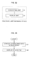
- This fracture limit obtaining device is for determining the fracture limit of a steel sheet in a process including one or more deformation path variations regarding a steel sheet, and is structured including a converting unit 1 converting a fracture limit curve in strain space obtained on a proportional loading path into a fracture limit curve in stress space, and a display unit 2 displaying the fracture limit curve in stress space obtained by the converting unit 1 as a stress FLD.
- the fracture limit curve in strain space is measured experimentally. Specifically, the fracture limit curve in strain space can be obtained, after a plurality of in-plane strain ratios regarding a steel sheet are obtained by a proportional loading experiment, using measurement values of fracture limit major strain ⁇ 1 and fracture limit minor strain ⁇ 2 in each of the strain ratios.
- Fig. 33 is a flowchart showing steps of a fracture limit obtaining method according to Example 1.
- the fracture limit curve in strain space is measured experimentally.
- the converting unit 1 converts a fracture limit curve in strain space measured experimentally into a fracture limit curve in stress space using the Mises' yield function for example (step S1).
- step S2 the fracture limit curve in stress space obtained in step S1 is displayed as a stress FLD on the display unit 2 (step S2).
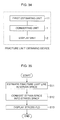
- Fig. 34 is a block diagram showing a main structure of a fracture limit obtaining device according to Example 2. Note that the same component members as those in Fig. 32 of Example 1 are given the same numerals, and detailed explanation thereof is omitted.
- This fracture limit obtaining device is for determining the fracture limit of a steel sheet in a process including one or more deformation path variations regarding a steel sheet , and is structured including a first estimating unit 11 estimating a fracture limit curve in strain space on a proportional loading path, a converting unit 1 converting the obtained fracture limit curve in strain space into a fracture limit curve in stress space, and a display unit 2 displaying the fracture limit curve in stress space obtained by the converting unit 1 as a stress FLD.
- Fig. 35 is a flowchart showing steps of a fracture limit obtaining method according to Example 1.
- the user inputs the material and the mechanical property values (t, YP, TS, El, U.E1, r value, n-th power hardening law/Swift hardening law) of a thin plate.
- the first estimating unit 11 estimates a fracture limit curve in strain space on a proportional loading path based on the mechanical property values inputted by the user (Step S11).
- the converting unit 1 converts the fracture limit curve in strain space estimated by the first estimating unit 11 into a fracture limit curve in stress space using the n-th power hardening law/Swift hardening law inputted as the mechanical properties , and for example the Mises' yield function or the like (Step S12). Subsequently, the fracture limit curve in stress space obtained in step S1 is displayed as a stress FLD on the display unit 2 (step S13).
- the method may also be arranged such that the strain FLD is estimated from a database (t, YP, TS, El, U.E1, r value, strain-stress multiple linear data) of shipping test values, and the stress FLD is calculated from the shipping test values (upper limit value and lower limit value in a quality dispersion distribution within a predetermined standard, and the mean value in the quality dispersion distribution).
- a database t, YP, TS, El, U.E1, r value, strain-stress multiple linear data
- Example 2 a modification example of Example 2 will be explained.
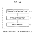
- a second estimating unit 12 is provided instead of the first estimating unit 11.
- the second estimating unit 12 identifies, as described above, the material parameter Kc based on one or more measurement values of fracture limit major strain ⁇ 1 and fracture limit minor strain ⁇ 2 .
- the functions of the respective components (except the display unit 4) constituting the fracture prediction devices according to the above-described examples and the like can be realized by operation of a program product stored in a RAM or ROM of a computer.
- the respective steps of the fracture prediction method and the fracture limit obtaining method steps S1 to S6 of Fig. 23 , steps S11 to S14 of Fig. 24 , and so on, steps S1 and S2 of Fig. 33 , steps S11 to S13 of Fig. 35 , and so on
- steps S1 and S2 of Fig. 33 steps S11 to S13 of Fig. 35 , and so on
- This program product and a computer readable recording medium recording the program product are included in the present invention.
- the aforementioned program product is provided to a computer by recording in a recording medium such as CD-ROM for example, or by transmitting via various types of transmission media.
- a recording medium such as CD-ROM
- the recording medium recording the program product other than the CD-ROM, it is possible to use a flexible disk, a hard disk, a magnetic tape, a magneto-optical disk, a non-volatile memory card, or the like.
- a transmission medium of the program product a communication medium in a computer network system for supplying program information by propagating as a carrier wave can be used.
- the computer network is a LAN, a WAN such as the Internet, a radio communication network, or the like
- the communication media is a wired line such as an optic fiber, a wireless line, or the like.
- the program product included in the present invention is not only one such that the functions of the above-described embodiments are realized by a computer executing the supplied program product.
- the program product cooperates with the OS (operating system), another application, or the like working on the computer to realize the functions of the above-described embodiments, such a program product is included in the present invention.
- the program product when all or part of processing of the supplied program product is performed by a function expansion board or a function expansion unit of the computer to realize the functions of the above-described embodiments, such a program product is included in the present invention.
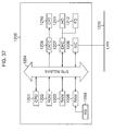
- Fig. 37 is a schematic diagram showing an internal structure of a personal user terminal device.
- numeral 1200 denotes a personal computer (PC) including a CPU 1201.
- the PC 1200 executes device control software which is stored in a ROM 1202 or a hard disk (HD) 1211 or supplied by a flexible disk drive (FD) 1212.
- This PC 1200 controls devices connected to a system bus 1204 in an integrated manner.
- Numeral 1203 denotes a RAM and functions as a main memory, a work area, or the like for the CPU 1201.
- Numeral 1205 denotes a keyboard controller (KBC) and controls an instruction input from a keyboard (KB) 1209, a not-shown device, or the like.
- KBC keyboard controller
- Numeral 1206 denotes a CRT controller (CRTC) and controls display on the CRT display (CRT) 1210.
- Numeral 1207 denotes a disk controller (DKC).
- the DKC 1207 controls access to the hard disk (HD) 1211 storing a boot program, a plurality of applications, edit files, user files, a network administration program, and so on, and to the flexible disk (FD) 1212.
- the boot program is a start-up program, a program starting execution (operation) of hardware and/or software of a personal computer.
- Numeral 1208 denotes a network interface card (NIC) and carries out bidirectional exchange of data via a LAN 1220 with a network printer, another network device, or another PC.
- NIC network interface card
- the present invention when predicting presence of fracture occurrence in a thin plate in a process including one or more deformation path variations, it is possible to obtain the fracture limit curve easily and efficiently and predict the presence of fracture occurrence with high prediction accuracy.
- the risk of fracture upon press forming or crash can be evaluated quantitatively, thereby realizing efficient and highly precise development of an automobile body optimized the material, the forming, and the body structure.
Landscapes
- Physics & Mathematics (AREA)
- Engineering & Computer Science (AREA)
- General Physics & Mathematics (AREA)
- Theoretical Computer Science (AREA)
- Geometry (AREA)
- Computer Hardware Design (AREA)
- General Engineering & Computer Science (AREA)
- Evolutionary Computation (AREA)
- Immunology (AREA)
- Health & Medical Sciences (AREA)
- Life Sciences & Earth Sciences (AREA)
- Analytical Chemistry (AREA)
- Chemical & Material Sciences (AREA)
- General Health & Medical Sciences (AREA)
- Biochemistry (AREA)
- Pathology (AREA)
- Automation & Control Theory (AREA)
- Aviation & Aerospace Engineering (AREA)
- Computational Mathematics (AREA)
- Mathematical Analysis (AREA)
- Mathematical Optimization (AREA)
- Pure & Applied Mathematics (AREA)
- Investigating Strength Of Materials By Application Of Mechanical Stress (AREA)
Abstract
Description
- The present invention relates to a fracture prediction method and a device as well as a program product and a recording medium for a thin plate formed of a metal material, and is particularly preferable as a fracture determining criterion for a material fracture in a crash process of an automobile member subjected to press-forming.
- The margin against a fracture is determined in general using a thinning criterion or a forming limit diagram (FLD). The FLD indicates the major and minor strain (ε1 and ε2, respectively) at which the failure occurs, and can be used in a crash analysis. The FLD can be experimentally determined by loading specimens along various proportional paths. Nakazima et al., for instance, operated hemispherical punch stretching for rectangular specimens with various widths. Before the forming operation, small circulars or grids are marked on the sheet surface by etching or printing. Theses circles are distorted into ellipses during the forming operation, which will be terminated at the onset of necking or crack. The size of an ellipse near the neck varies with the width of the specimen. The major and minor strains are measured from the ellipse at the neck or crack. Finally, the forming limit curve (FLC) is drawn so that it fits the measured limit strains for various paths.
-
Fig. 1 shows a fracture limit curve measured by experiment. - As an FLD prediction method, there are combined usage of Hill's criterion and Swift's one, Marciniak-Kuczynski model, Storen-Rice model, and the like, and the FLD can be obtained by correcting the influence of a sheet thickness by a Keeler's empirical rule. The tearing can be produced by a dynamic FE code, whereas the former cannot be detected in the FE analyses. Instead of direct predictions of the tearing, the computed strains are compared with critical values external prepared and it is regarded that the failure occurs when one of the computed strains reaches the limit.
- Non-patent Document 1: Journal of the Japan Society for Technology of Plasticity, 45, 123, 2004
- Non-patent Document 2: CAMP-ISIJ 17, 1063, 2004
- Non-patent Document 3: Metal Forming, Hosford, 319, 1993
- Non-patent Document 4: Transactions of the Japan Society of Mechanical Engineers, Series A, 54, 1617, 1998
- Schematic illustration of experimental forming limit strains for (a) proportional loading, (b) uniaxial tension followed by equi-biaxial stretching, (c) equi-biaxial stretching followed by plane-strain stretching, and (d) equi-biaxial stretching followed by uniaxial tension (
Figure2). Figure2 have shown that the maximum curve is observed in uniaxial tension followed by equi-biaxial stretching, whereas the minimum one is obtained for the opposite sequence. The FLC for equi-biaxial stretching followed by plane-strain stretching is slightly higher than the minimum ones. - In a car crash deformation process of an automobile body part subjected to press-forming or pre-deformation in press-forming, the strain path often changes. When evaluating a fracture using the forming limit strains obtained by experiment, forming limits strains must be prepared according to the an infinite number of strain paths. Therefore, in practice, the forming limit strain with respect to a proportional loading path needs to be used for evaluation of a fracture, and hence high prediction accuracy cannot be expected.
- Further, steel sheets failure occurs under stretch-flanging when a stretch strain in the circumferential direction of a cutting edge reaches the critical value. The stress state in the cutting edge portion is close to the uniaxial tension, but abrupt gradients of stress and strain exist inward from the cutting edge portion. Thus, the fracture limit indicates a value that is quite different compared to the fracture limit strain or stress obtained by a uniaxial tensile test. Specifically, high-strength steels over 590MPa suffer from the breakage under stretch-flanging, even when the cutting edge portion reaches a plastic instability and localized necking (thickness necking) occurs, the inside material excluding the cutting edge portion has not satisfied the plastic instability yet. Thus, being restrained by the inside material, the plastic instability cannot be reached as the whole, and progress of the localized necking is delayed.
- Furthermore, in the stretch-flanging limit, a large number of thickness necks are formed in a circumferential direction of the cutting edge portion, and thus the fracture is delayed. For example, assuming that a localized necking is formed at one position in the cutting edge portion, stress in the circumferential direction in the vicinity of the localized necking is eased. However, the influence of this ease of stress decreases with distance from the localized necking, and when the deformation proceeds further, a next localized necking is formed at a separated location from the first localized necking. When the deformation proceeds still further, a new neck is formed. Repeating this process, a large number of thickness necks are formed in the circumferential direction of the cutting edge portion, and the localized necking grow. Here, reason why the previously formed sheet thickness necks grow but do not lead to a fracture is that they are restrained by a material having a small strain, and does not satisfy the plastic unstableness as the entire cutting edge portion in the circumferential direction. Therefore, in the stretch-flanging limit, when a thickness neck is formed at one position in the circumferential direction of the cutting edge portion, it does not lead to a fracture but is delayed.
- Thus, the prediction method for the stretch-flanging limit is not easy due to existence of the strain gradient inward from the cutting edge portion, and to a delay effect such that a fracture does not occur even when one position in the circumferential direction satisfies the localized necking. Thus, such a method is not proposed hitherto.
- The present invention is directed to solving the above-described problems of conventional arts as technical problems, and an object thereof is to provide a fracture prediction method by which, when predicting presence of fracture occurrence in a steel sheet in a process including one or more strain paths , the fracture limit curve can be obtained easily and efficiently and presence of fracture occurrence can be predicted with high prediction accuracy, and the risk of fracture upon press forming or crashworthiness can be evaluated quantitatively, thereby realizing efficient and highly precise development of autobodies optimizing the material, the forming , and the car body structures for crash safety .
- A fracture prediction method of the present invention is a method evaluating a fracture limit of a thin plate constituted of a metal material, and the method includes, when predicting fracture occurrence in the thin plate in a plastic deformation process according to one or more deformation path changes, a procedure of converting a fracture limit curve in strain space into a fracture limit curve in stress space, and a procedure of predicting presence of the fracture occurrence using the obtained fracture limit curve in stress space.
- Further, as a result of dedicated studies for solving the above-described problems, the present inventors have devised several aspects of the invention as follows. It is made clear that prediction with high accuracy is possible by using a hole expansion ratio having a good correlation with a stretch-flanging limit as a criterion for a fracture, and further by performing fracture determination in stress space in which the influence of a deformation history can be considered, instead of strain space.
- Further, as a result of dedicated studies for solving the above-described problems, the present inventors have devised several aspects of the invention as follows. A fracture limit obtaining method of the present invention is a method of obtaining a fracture limit used for determining a fracture limit of a thin plate constituted of a metal material, in which a stretch strain ratio λ obtained from a hole expansion test is converted into a fracture limit curve in stress space when determining a fracture limit of the thin plate in a process including one or more deformation path variations.
- The fracture limit curve expressed in stress space does not depend on a deformation path, and hence can be expressed by a single limit curve. Therefore, using this as a fracture determining criterion, a fracture in a stretch flange portion including one or more deformation path variations can be determined with high accuracy.
- According to the present invention, when predicting presence of fracture occurrence in a thin plate in a process including one or more deformation path variations, it is possible to obtain the fracture limit curve easily and efficiently and predict the presence of fracture occurrence with high prediction accuracy. Thus, the risk of fracture upon press forming or crash can be evaluated quantitatively, thereby realizing efficient and highly precise development of an automobile body considering the material, the construction method, and the structure at the same time.
-
-
Fig. 1 is a diagram showing a forming limit diagram (FLD) used for explaining a conventional art; -
Fig. 2 is a forming limit diagram used for explaining the problems to be solved by the present invention; -
Fig. 3 is a diagram for explaining conversion from a strain into a stress; -
Fig. 4 is a diagram for explaining a coordinate transformation law; -
Fig. 5 is a diagram showing that, while an FLD of strain space depends on a strain path and a fracture limit curve thereof varies largely, a fracture limit curve in stress space can be expressed by a single curve; -
Fig. 6 is a diagram showing a relationship between a punch stroke and maximum major strain; -
Fig. 7 is a diagram showing comparison of prediction accuracy when performing a numerical simulation with various analysis conditions and using an FLD obtained by experiment and a localized necking occurrence limit as a fracture determining criterion; -
Fig. 8 is a diagram showing a positional relationship between a stress history in a formation process obtained by a numerical simulation and a fracture limit curve; -
Fig. 9 is a diagram showing prediction accuracy of a present invention method; -
Fig. 10 is a diagram showing a part with a hat cross-sectional shape, which is a target of verifying prediction accuracy of a crash analysis and the overview of a three-point bending drop weight test; -
Fig. 11 is a diagram showing an analysis result of draw-bending formation of a hat shape by a numerical simulation; -
Fig. 12 is a diagram showing a relationship between an equivalent plastic strain and an equivalent stress according to a strain speed; -
Fig. 13 is a diagram showing a positional relationship between a dynamic fracture stress limit curve in stress space and a dynamic stress obtained from a crash simulation; -
Fig. 14 is a diagram showing a positional relationship between a stress history in a formation process obtained by a numerical simulation and a fracture limit curve, and prediction accuracy of the present invention method; -
Fig. 15 is a diagram used for explaining an example of the present invention, and is a diagram explaining an experiment method; -
Fig. 16 is a diagram used for explaining the example of the present invention, and is a diagram explaining an analysis model; -
Fig. 17 is a diagram used for explaining the example of the present invention, and is a diagram contour displaying an analysis result with respect to a major strain distribution; -
Fig. 18 is a diagram used for explaining the example of the present invention, and is a diagram showing a relationship between a distance from a hole edge and a maximum major strain regarding the analysis result; -
Fig. 19 is a diagram used for explaining the example of the present invention, and is a diagram showing a relationship between a distance from a hole edge and a maximum major strain regarding the analysis result; -
Fig. 20 is a diagram used for explaining the example of the present invention, and is a diagram showing a positional relationship between a stress history in a formation process obtained by a numerical simulation and a necking occurrence limit stress line; -
Fig. 21 is a diagram used for explaining the example of the present invention, and is a diagram showing a positional relationship between a stress history in a formation process obtained by a numerical simulation and a necking occurrence limit stress curve , and a fracture determining criterion obtained by converting a hole expansion ratio into stress space; -
Fig. 22 is a block diagram showing a main structure of a fracture prediction device according to this example; -
Fig. 23 is a flowchart showing steps when performing fracture prediction in a formation process of a thin plate constituted of a metal material, with a fracture prediction method according to this example; -
Fig. 24 is a flowchart showing steps when performing fracture prediction in a crash process, continued from the fracture prediction in a formation step ofFig. 23 , with the fracture prediction method according to this example; -
Fig. 25 is a diagram used for explaining an example of the present invention, and is a forming limit diagram (FLD) measured by experiment; -
Fig. 26 is a diagram used for explaining the example of the present invention, and is a forming limit diagram (FLD) considering the influence of a steel thickness using a Keeler's steel thickness correction rule with respect to a plastic unstableness limit curve predicted by Hill-Swift theory and Storen-Rice model; -
Fig. 27 is a diagram used for explaining the example of the present invention, and is a forming limit diagram (FLD) predicted using a stress increment dependency law based on the Storen-Rice model; -
Fig. 28 is a diagram used for explaining the example of the present invention, and is a diagram explaining conversion from a strain into a stress; -
Fig. 29 is a diagram used for explaining the example of the present invention, and is a diagram showing that, while an FLD of strain space depends on a deformation path and a fracture limit thereof varies largely, a fracture limit curve in stress space can be expressed by a single curve; -
Fig. 30 is a diagram used for explaining an example of the present invention, and is a diagram explaining an experiment method; -
Fig. 31 is a diagram used for explaining the example of the present invention, and is a diagram showing a fracture limit stress line expressing a hole expansion ratio in stress space; -
Fig. 32 is a block diagram showing a main structure of a fracture limit obtaining device according to Example 1; -
Fig. 33 is a flowchart showing steps of fracture limit obtaining method according to Example 1; -
Fig. 34 is a block diagram showing a main structure of a fracture limit obtaining device according to Example 2; -
Fig. 35 is a flowchart showing steps of a fracture limit obtaining method according to Example 2; -
Fig. 36 is a block diagram showing a main structure of a fracture limit obtaining device according to a modification example of Example 2; and -
Fig. 37 is a schematic diagram showing an internal structure of a personal user terminal device. - The margin against a fracture when evaluating formability is determined in general using a thinning criterion or an FLD, which can be used for fracture prediction in a car crash analysis as well. Among them, the FLD is known to vary largely depending on a strain path changes, and cannot be expected to have high prediction accuracy as a method of evaluating a fracture in a plastic deformation process, in which the deformation path varies largely as in crash of an automobile body part subjected to press-forming or pre-deformation in press-forming.
- However, recently Kuwabara et al. (refer to
Non-patent documents 1, 2) verified by experiment and analysis that, using a fracture limit curve expressed in stress space with an aluminum extruded material or mild steel sheets being the subject, the fracture limit can be represented almost uniquely without depending on the path of deformation. This knowledge relates to aluminum or mild steel sheets and is not clarified for high strength steels over 440 MPa, and hence cannot be used for current development of an automobile body in which high-strength steel sheets are mainly used. - Accordingly, the present inventors have reached the following items for the first time.
- (1) When a detailed experiment is performed on high-strength steel sheets having tensile strength of 440 MPa or higher and a fracture limit curve expressed in stress space is used, the fracture limit can be expressed by a single fracture limit curve without depending on the deformation path. (2) By using the fracture limit curve expressed in stress space, it is possible to predict a fracture evaluation in a plastic deformation process with high accuracy, in which the deformation path varies largely as in crash of an automobile body part subjected to press-forming or pre-deformation in press-forming.
- Hereinafter, a first embodiment will be explained in detail based on various examples.
- First, a method of obtaining the fracture limit curve in stress space will be explained. With a steel sheet shown in Table 1 below being the subject, there were measured (1) a fracture limit strain on a proportional loading path, and (2) a fracture limit strain under a deformation path variation. Here, t represents the thickness of a thin plate, YP represents proof strength, TS represents ultimate tensile strength, U.E1 represents uniform elongation, El represents total elongation, rm represents average r value (indicating a Lankford value and is expressed by rm = (ro + 2r45 + r90)/4 where r value in the rolling direction is r0, r value in the 45° direction with respect to the rolling direction is r45, and r value in the 90° direction with respect to the rolling direction is r90), and K, ε0, n represent material parameters obtained when a stress-strain curve obtained from a uniaxial tensile test is fitted in a function expression

- For the fracture limit strain on a proportional loading path, a fracture strain was measured with a scribed circle diameter being 6 mm by a uniaxial tension, a Nakajima method ( hemispherical punch stretching using a Teflon (registered trademark) sheet), and a hydraulic bulge test. On the other hand, for the fracture limit curve under strain path changes, after a tension of 10% along the rolling direction is performed as first deformation, a fracture strain was measured by the uniaxial tension and the Nakajima method so that the direction of 90° degrees from the primary extension direction is the maximum principal stress.
-
[Table 1] MECHANICAL PROPERTY VALUES OF MATERIAL AND MATERIAL PARAMETERS t/mm YP Ts U.El El rm K ε0 n 1.2 460 598 12 23 1.00 937 0.0108 0.157 (UNIT t: mm; YP, TS, K: MPa; El, U.E1: %) - Conversion from a strain to a stress becomes possible by assuming (1) incompressibility, (2) Mises' yield function, (3) material hardening law with isotropy, (4) normality rule, and (5) membrane state of stress. Hereinafter, a specific method for converting the fracture limit curve in strain space into stress space will be explained.
- The FLD of strain space is a diagram showing a major strain ε11 giving the fracture limit for each minor strain ε22, and a thickness strain ε33 can be obtained by them and the constant volume law


- Using the Mises' yield function for a yield surface for example, the equivalent plastic strain εeq can be represented as


- In addition, a high-degree anisotropic yield function may be used as necessary, but it has many parameters and requires considering the direction in a plate surface while processing, and hence provides insufficient improvement in precision even though it is complicated. Thus, in practice, the yield function assuming planar isotropy is sufficient. In either yield function, the equivalent plastic stress σeq considering a deformation path variation can be obtained using the equivalent plastic strain εeq obtained by integrating an equivalent plastic strain increment dεeq on a strain path and the work-hardening law.
- Next, a deviation stress component σij is obtained by isotropic hardening of yield surface shown in
Fig. 3 and the normality rule

- Note that when the main axis of the strain and the rolling direction do not match as shown in
Fig. 4 , a coordinate transformation operation shown below is necessary. In the diagram, xi represents x1 axis//RD, x2 axis//TD, x3 axis//ND which coordinate axes of a material coordinate system, and Xi represents the main axis of the strain in an n-th order deformation. When a component display on the material coordinate system of a tensor A is Âij, and a coordinate converted tensor is R, (1) a strain component εij measured by an experimental coordinate system can be converted into a strain component


-
Fig. 5 shows an FLD measured by experiment, and a fracture limit curve obtained by converting the FLD into stress space with a major stress and a minor stress by the aforementioned method. - The FLD of strain space depends on the deformation path and the fracture limit curve varies largely, but the fracture limit curve expressed in stress space becomes a single fracture limit curve.
- Further, the present inventors demonstrated that, as a result of performing experiments and studies on high-strength steel sheets of 440 MPa to 980 MPa classes shown in Table 2 below, regardless of the tensile strength of a material or strengthening mechanism, single fracture limit curves are produced in a wide range. Using these fracture limit curves expressed in stress space, fracture evaluation in a plastic deformation process in which the deformation path varies largely, as in a car crash of an automobile body part subjected to press-forming or pre-deformation in press-forming, can be predicted with high accuracy.
- Note that, as a matter of course, a fracture limit curve obtained by converting an FLD measured by an experimental method other than the Nakajima method into stress space may be used, or a fracture limit curve obtained by converting a theoretical FLD of Hill's localized necking model, Swift's diffuse necking model, Marciniak-Kuczynski method, Storen-Rice model, or the like into stress space may be used for the fracture prediction.
-
[Table 2] MECHANICAL PROPERTY VALUES OF MATERIAL AND MATERIAL PARAMETERS MATERIAL t YP TS U.El El A: 440 MPa SOLID SOLUTION-HARDENED STEEL 1.2 368 460 18 35 B: 590 MPa PRECIPITATION-HARDENED STEEL 1.2 460 598 12 23 C: 780 MPa DUAL-PHASE STEEL 2.0 490 840 10 19 D: 980 MPa DUAL-PHASE STEEL 2.0 710 1010 8 14 (UNIT t: mm; YP, TS: MPa; El, U.El: %) - Next, a method of evaluating a fracture limit will be explained.
For predicting fracture of a material by a numerical simulation by a finite element method (FEM), there are technical problems as follows. - (1) An FLD measured by experiment is affected strongly by a distance between evaluation points and a friction state. Thus, when using the FLD as a fracture determining criterion, correction according to analysis conditions of the numerical simulation is necessary.
- (2) In the numerical simulation, increase of strain up to a uniform deformation can be simulated precisely, but for simulating localized necking occurring in a region to the extent of a sheet thickness or a shear band in which the strain is localized in a narrower region, finite elements have to be segmented adequately. Thus, the prediction is difficult with the performance of current computers.
- (3) With the material constitutive law adopted normally in general purpose software, localization of a strain is delayed, and hence evaluation on the risk side is given when the actually measured FLD is taken as the fracture determining criterion.
- As a result of dedicated studies on these problems, the present inventors clarified a fracture determining criterion suitable for numerical simulations. With the steel sheets shown in Table 1 being taken as subjects, the FEM numerical simulation of hemispherical punch stretching is performed, and influences of an element size and a material constitutive equation on the localization process of a strain are examined.
-
Fig. 6 shows a relationship of a maximum major strain introduced by punch-stroke and press-forming.
The influences of the element size and the material constitutive equation barely appear from the beginning of the formation to the punch-stroke of approximately 25 mm, but these influences become obvious beyond 25 mm where localization of the strain begins. -
Fig. 7 shows comparison of prediction accuracy when performing the numerical simulation with various analysis conditions and using an FLD obtained by experiment and a localized necking occurrence limit as a fracture determining criterion.
When the actually measured FLD is used as the fracture determining criterion, the localization process of a strain cannot be simulated precisely, and thus the accuracy of fracture prediction is not high. On the other hand, when the localized necking occurrence limit is used as the fracture limit, prediction with relatively high accuracy becomes possible regardless of the element size and the used material constitutive equation, and evaluation on the safe side can be obtained. This suggests that the localized necking occurrence limit may be used as the fracture determining criterion in practice because a ductile fracture in a steel sheet occurs at a position where deformation is localized by localized necking, and when localized necking occurs it leads to a fracture by very short time. - The localized necking occurrence limit can be handled within the framework of plastic instability, and can be predicted by a theoretical FLD of Hill's localized necking model, Swift's diffuse necking model, Marciniak-Kuczynski method, Storen-Rice model, or the like.
- As shown in this case example, as a result of dedicated studies, the present inventors have found that high prediction accuracy can be assured by using as the fracture determining criterion the fracture limit curve obtained by converting a necking start curve in strain space into stress space when evaluating a fracture by the numerical analysis simulation using the finite element method.
- Next, a case example of the method of evaluating a fracture limit will be explained.
There is shown a case example of fracture prediction on a non-linear path such that with the steel sheets shown in Table 1 being the subjects, an uniaxial tension of 10% in the rolling direction is performed as first deformation, and thereafter plane strain deformation is performed by hemispherical punch stretching .
Fig. 8 shows a relationship between a stress history in a formation process obtained by a numerical simulation and a fracture limit curve obtained by converting a necking start curve in strain space into stress space. - When using a dynamic explicit method for the numerical simulation, the obtained stress increases while vibrating largely because propagation of a stress wave is solved at minute time intervals without performing repetitive calculation within a time step. With this method of comparing a positional relationship between a stress and a fracture limit stress to evaluate a fracture, it is difficult to assure high prediction accuracy.
- As a result of dedicated studies, the present inventors have devised a method of determining a fracture with high accuracy, which can avoid, when using the dynamic explicit method for the numerical simulation, vibration of a stress by converting a plastic strain into a stress by post-processing.
-
Fig. 9 shows results of predicting a fracture with the present invention method.
With a conventional fracture prediction method by means of FLD, prediction with high accuracy is difficult since the fracture limit curve varies largely depending on a deformation path. In contrast, by applying the present invention, it can be seen that a fracture can be predicted with good accuracy even when the deformation path varies. In addition, the present invention is also able to evaluate a fracture by comparing a positional relationship between a value obtained by converting an experimental strain measurement result into a stress and a fracture limit curve, instead of performing the numerical simulation using the finite element method. - Next, an example of applying the fracture prediction method to a crash analysis will be explained.
With the steel sheets shown in Table 1 being the subjects, the fracture prediction method of the present invention is applied in a three-point bending crash analysis of a member shown inFig. 10 with a hat cross-section and a length of 900 mm. - First, an analysis of draw-bending in a hat shape was performed using the numerical simulation of the dynamic explicit code. The result of the forming simulation is shown in
Fig. 11 . Next, a finite element model for a crash analysis is created, on which spot-welding processing with a flat plate (with a relative displacement between two contact points being fixed) at 30 mm intervals is performed at a flange portion. - Further, the obtained forming analysis result is reflected on this finite element model for a crash analysis, and the crash analysis is performed by the numerical simulation by the dynamic explicit code. When evaluating a fracture in a material in a crash process after press-forming, the deformation history during formation can be considered by inheriting a thinning and an equivalent plastic strain obtained by the numerical simulation of press-forming, or a thinning and an equivalent plastic strain, a stress tensor, a strain tensor as initial conditions of the crash analysis.
- Note that, as a matter of course, the deformation history during formation can be considered by measuring a thickness of a press-formed product and an equivalent plastic strain by an experiment instead of the numerical simulation and inheriting one of them as an initial condition of the crash analysis.
- In the case examples up to now, the quasi-static plastic deformation process such as press-forming is handled, but a mechanical characterization at high strain rates needs to be considered in the car crash analysis. It is known that steels have strain rate dependency, and flow stress increases when the deformation speed is high. When an automobile crash, the strain rate may reach 1000/s in a corner where deformation concentrates. For assuring prediction accuracy in the crash analysis, it is necessary to consider accurate mechanical characterization at high strain rates.
- Generally, when performing the crash analysis with the numerical simulation by the finite element method, the Cowper-Symonds equation is used as a material model representing increase of stress according to a strain rate.
Fig. 12 shows a relationship between an equivalent plastic strain and an equivalent stress according to a strain rate, andFig. 13 shows a positional relationship between a dynamic fracture stress limit curve in stress space and a dynamic stress obtained from a crash simulation. - When evaluating a fracture using the dynamic stress obtained from the crash simulation, a large number of dynamic fracture stress limit curves are needed depending on the strain rate, and practically it is difficult to predict the fracture.
- As a result of dedicated studies to solve this problem, the present inventors have found that the stress at a reference strain speed obtained by converting a plastic strain obtained from the crash simulation may be used, and only the fracture stress limit curve at the single reference strain rate may be used as the fracture limit (fracture criterion) used for fracture determination. As a result of consideration, it is found that the reference strain rate may be a quasi-static strain rate. Although the range of the quasi-static strain rate differs depending on the material, the fracture limit curve measured in the range of 0.001/s to 1/s may be used in practice.
-
Fig. 14 shows a result of predicting a fracture with the method of the present invention.
With a conventional fracture prediction method by means of FLD, it is difficult to predict with high accuracy a plastic deformation process in which a deformation path varies largely as in a crash phenomenon after subjected to pre-deformation in press-forming. However, it can be seen that by applying the present invention, a fracture can be predicted with good accuracy even in a crash process after press-forming. - As shown in the above examples, according to the present invention, a risk of fracture can be evaluated quantitatively from data obtained by simulating press-forming and crash processes of a steel sheet by a finite element method. Here, the Cowper-Symonds equation is used as a representative example as the strain rate dependency of a deformation stress, but the effectiveness of the present invention does not change even using an arbitrary constitutive equation, for example an m-th power hardening equation, a Johnson-Cook equation, or the like, with which the strain rate dependency can be considered.
- Hereinafter, as several specific examples of the present invention, a stretch-flanging limit evaluation method with a hole expansion ratio λ in stress space being a criterion will be shown.
As test specimens, we used sheets, 1.2mm in thickness, of a cold-rolled and continuously annealed, dual phase steel, having the mechanical properties shown in Table 3. The mechanical properties are obtained using JIS-5 specimens cut out in the rolling direction of the steel sheets and a screw-driven tester at a cross-head velocity of 10mm/min (a strain rate of 3×10⁻³/s). -
[Table 3] TENSILE PROPERTIES OF DUAL-PHASE STEEL SHEET t/mm YP/MPa TS/MPa U.El(%) El(%) K/MPa ε0 n' rm 1.2 354 614 17 30 1109 0.0070 0.230 0.89 (YP: PROOF STRENGTH, TS: ULTIMATE TENSILE STRENGTH, U.El: UNIFORM ELONGATION, El: TOTAL ELONGATION, rm: LANKFORD VALUE) - First, the steel sheet was sheared by the size of 200 mm × 200 mm, and a hole with a diameter of 25 mm was punched through a center portion using a punch and a die. This steel sheet with a hole in the center was subjected to formation (Teflon sheet lubrication) with a flat-bottom punch with a diameter of 100 mm and a die shoulder R of 15 mm until a fracture occurs at a hole edge, and the hole diameter and the forming limit height when the fracture occurred were measured. The overview of the experiment is shown in
Fig. 15 . Further, the FLD was measured by the Nakajima method (hemispherical punch stretching using a Teflon sheet) for use as the criterion for fracture prediction in the numerical simulation. - Subsequently, the numerical simulation by the dynamic explicit FE code was performed to verify the prediction accuracy of a stretch-flanging limit that fractures from cutting edge. Note that the material parameters provided for the numerical simulation are the ones used for the experiment, and the tools comply with those of the experiment. An analysis model is shown in
Fig. 16 . The element size of 2 mm is used, which is equal to the distance between evaluation points when measuring the FLD, and a Hill's anisotropic yield function is used as the yield function for consideration. -
Fig. 17 shows simulation results of the stretch-flanging forming by the cylindrical flat-bottom punch, andFig. 18 shows a relationship between the distance from the hole edge and the major strain. From them, it can be seen that a large strain is introduced to the hole edge of the cutting edge and that a large strain gradient exists inward from the edge hole.Fig. 19 shows a relationship between a stress history, in which a plastic strain obtained from the numerical simulation is converted into stress space and plotted for every forming height, and a "necking occurrence limit stress curve" obtained by converting into stress space a "necking occurrence limit curve", which is obtained by offsetting a forming limit curve measured on a proportional loading path so that the limit value in a plane strain becomes equal to n value. The stress at the hole edge reaches the necking occurrence limit stress curve at the forming height of 14 mm, which differs largely from the forming limit height of 18.5 mm measured actually by experiment. On the other hand, the fracture was evaluated in stress space with the fracture criterion being set to the hole expansion ratio. Note that the hole expansion ratio is defined by the following equation.

-
Figs. 20, 21 shows results of predicting a fracture by the present invention method. When a conventional "necking occurrence limit stress curge" is used as the fracture criterion in a stretch - flanging forming , the forming limit height is estimated low due to presence of a strain gradient inward from a cutting edge and a delay effect such that one position in the circumferential direction does not fracture when it satisfies the localized necking. However, it can be seen that the use of the criterion obtained by converting the hole expansion ratio into stress space for fracture determination allows to predict the fracture with good accuracy. - Hereinafter, in view of the above-described overall structure of the present invention, a specific example will be explained with reference to the drawings.
Fig. 22 is a block diagram showing a main structure of a fracture prediction device according to this example.
This fracture prediction device is for predicting presence of fracture occurrence in a steel sheet in a process including one or more deformation path variations regarding a steel sheet constituted of a metal material, and is structured including anestimating unit 21 estimating a fracture limit curve in strain space on a proportional loading path, a convertingunit 22 converting the fracture limit curve in strain space obtained on the proportional loading path into a fracture limit curve in stress space, afracture determining unit 23 determining presence of fracture occurrence with the fracture limit curve in stress space, and adisplay unit 24 displaying a determination result by thefracture determining unit 23, or the like. - The estimating
unit 21 uses the approximate equation
necking model 
necking model 
- The estimating
unit 1 may also be configured to obtain the necking occurrence limit in strain space using an approximate equation
unit 21 identifies the material parameter Kc based on one or more measurement values of maximum fracture limit strain ε1 and minimum fracture limit strain ε2. - Note that in this example, the case where the fracture limit curve in strain space is estimated theoretically using the
estimating unit 21 is exemplified, but the fracture limit curve in strain space may be measured experimentally without using theestimating unit 21. Specifically, the fracture limit curve in strain space can be obtained, after a plurality of in-plane strain ratios regarding a thin plate are obtained by a proportional loading experiment, using measurement values of maximum fracture limit strain ε1 and minimum fracture limit strain ε2 in each of the strain ratios. - When converting the fracture limit curve in strain space into the fracture limit curve in stress space, the converting
unit 22 performs the aforementioned conversion using the vertical rule of yield surface as the plastic strain increment law. Specifically, as described above, the Mises' yield function
- The
fracture determining unit 23 performs evaluation by comparing the positional relationship between the fracture limit curve in stress space converted by the convertingunit 21 and the strain state of each portion obtained from results of the simulation by the finite element method in a plastic deformation process, and determines that it is a fracture or that the risk of fracture is high when the strain in the deformation process reaches this limit strain. Here, as the method of the numerical analysis, the dynamic explicit method is used, which is one of finite element methods. In this case, the plastic strain obtained by the dynamic explicit method is converted into a stress and is compared with the fracture limit curve in stress space. - Note that the
fracture determining unit 23 may also be configured to convert a strain obtained from deformation conditions of a thin plate evaluated by experiment into a stress and evaluate quantitatively presence of fracture occurrence using the fracture limit curve in stress space, instead of performing the aforementioned simulation. - Here, in the case where a rapid deformation occurs in a thin plate as in a crash analysis of an automobile member, the
fracture determining unit 23 executes a numerical analysis considering the speed dependency of a flow stress in the thin plate, converts the plastic strain obtained from the numerical analysis to calculate the stress at the reference strain speed, and compares this stress with the fracture limit curve in stress space corresponding to the reference strain rate . -
Fig. 23 is a flowchart showing steps when performing fracture prediction in a forming process of a thin plate constituted of a metal material, with the fracture prediction method according to this example.
First, based on the material of the thin plate and the mechanical property values (t, YP, TS, El, U.El, r value, n-th power hardening law/Swift hardening law) which are inputted by the user, the estimatingunit 21 estimates a fracture limit curve in strain space on a proportional loading path (step S1). - Subsequently, the converting
unit 22 converts the fracture limit curve in strain space measured experimentally into a fracture limit curve in stress space using the Mises' yield function, so as to create a stress FLD (step S2). - Subsequently, the
fracture determining unit 23 performs evaluation by comparing the positional relationship between the fracture limit curve in stress space converted by the convertingunit 21 and the strain state of each portion obtained from results of the simulation by the finite element method (here, the dynamic explicit method) in a plastic deformation process, and determines a fracture or the risk of fracture (step S3). - In step S3, when it is determined that the limit strain is reached and a fracture occurs in the thin plate or that the risk of fracture is high, the
fracture determining unit 23 executes the following several processing (step S4).
The element ID, the thickness of the thin plate, the strain, and the stress information are outputted to a log file. Further, the element that has reached the criterion is erased, and the analysis after the fracture is continued. - Subsequently, the following various displays are performed on the display unit 24 (step S5).
The risk that a fracture occurs in the thin plate is contour displayed by a scalar amount. Further, the stress history of the fracture risk portion in stress space and the criterion are displayed. The risk of occurrence of a crease in the thin plate is contour displayed together. Here, the risk of fracture may be displayed with respect to dispersion (average value, lower limit value) within the standard of shipment test values. - On the other hand, when it is determined in step S3 that there is no possibility of occurrence of a fracture or that the risk thereof is low, an indication about this is displayed on the
display unit 24 in step S6. -
Fig. 24 is a flowchart showing steps when performing the fracture prediction in the crash process, continued from the fracture prediction in the formation step ofFig. 23 , with the fracture prediction method according to this example. - In this case, the stress FLD created in step S2 of
Fig. 23 is inherited and used.
Then, thefracture determining unit 23 executes a numerical analysis considering the strain rate dependency of a deformation stress in the thin plate, converts the plastic strain obtained from the numerical analysis to calculate the stress at the reference strain rate, and compares this stress with the fracture limit curve in stress space corresponding to the reference strain rate, thereby determining a fracture or the risk of fracture (step S11). - In this step S11, the
fracture determining unit 23 inherits deformation conditions of the thin plate evaluated by the numerical analysis in the formation process ofFig. 23 as an initial condition of the numerical analysis in the crash process. The deformation conditions are thinning and an equivalent plastic strain or thinning, an equivalent plastic strain, a stress tensor and a strain tensor. - In step S11, when it is determined that a fracture occurs in the thin plate or that the risk of fracture is high, the
fracture determining unit 23 executes the following several processing (step S12).
The element ID, thinning, the strain, and the stress information are outputted to a log file. Further, the element that has reached the criterion is erased, and the analysis after the fracture is continued. - Subsequently, the following various displays are performed on the display unit 24 (step S13).
The risk that a fracture occurs in the thin plate is contour displayed by a scalar amount. Further, the stress history of the fracture risk portion in stress space and the criterion are displayed. The risk of occurrence of a crease in the thin plate is contour displayed together. Here, the risk of fracture may be displayed with respect to dispersion (average value, lower limit value) within the standard of shipment test values. - On the other hand, when it is determined in step S11 that there is no possibility of occurrence of a fracture in the thin plate or that the risk thereof is low, an indication about this is displayed on the
display unit 24 in step S14. - As explained above, according to this example, when determining the fracture limit of a thin plate in a process including one or more deformation path variations, it is possible to obtain the fracture limit curve easily and efficiently and determine the fracture limit with high prediction accuracy. Thus, the risk of fracture upon press forming or crash can be evaluated quantitatively, thereby realizing efficient and highly precise development of an automobile body optimized the material, the forming, and the body structure.
- -Second Embodiment-Conventionally, the margin against a fracture is often evaluated by a thinning, but due to popularization of numerical simulations and advancement in functions of post-processing software, fracture evaluation methods using a forming limit diagram (FLD) are started to be used widely. The FLD can be obtained by an experiment such as the Nakajima method. However, such a method is complicated, and it is difficult to construct a database for various types of steel sheet menus and thickness. Thus, several prediction approaches have been proposed.
- For example, in post-processing functions of general-purpose software, there is incorporated a method (refer to Non-patent document 1) in which a Keeler's thickness correction empirical rule is added to the Hill's localized necking model and the Swift's diffuse necking model. However, prediction values obtained with these theories allow to predict for aluminum or mild steel with relatively high accuracy, but for steel sheets with tensile strength of 440 MPa class or higher, they are overestimated on the uniaxial tension side and underestimated on the equi-biaxial stretching side. Thus, they are not suitable for current development of an automobile body in which high-strength steel sheets are mainly used.
- Further, the FLD is known to vary largely depending on a deformation path. High prediction accuracy cannot be expected therefrom as a method of evaluating a fracture in a plastic deformation process, in which the deformation path varies largely as in crash of an automobile body part subjected to press-forming or pre-deformation in press-forming. However, recently Kuwabara et al. (refer to
Non-patent documents 1, 2) verified by experiment and analysis that, using a fracture limit curve expressed in stress space with an aluminum extruded material or mild steel being the subject, the fracture limit can be represented almost uniquely without depending on the path of deformation. This knowledge relates to aluminum or mild steel and is not clarified for steel sheets with tensile strength of 440 MPa class or higher. - Accordingly, the present inventors conducted detailed experiments on high strength steels with tensile strength of 440 MPa or higher, and have reached the following items for the first time.
- (1) The FLD of strain space obtained on a proportional loading path can be predicted highly accurately using a stress-strain curve obtained from a uniaxial tensile test and the thickness of a virgin material or a stress-strain curve, the thickness of a virgin material, and a parameter Kc defining stress increment dependency. Thus, an FLD database of strain space for various types of steel sheet menus and thickness can be constructed easily and simply.
- (2) Fracture determination in a process including one or more deformation path variations is possible by converting the FLD of strain space obtained on the proportional loading path into stress space and determining a fracture in stress space.
- Hereinafter, the second embodiment will be explained in detail based on several examples.
- First, a method of measuring the FLD of strain space experimentally will be explained.
The fracture limit strain is measured by a proportional loading experiment with a steel sheet constituted of a metal material having mechanical property values and material parameters shown in Table 1 below being the subject. Here, t represents the thickness of a thin plate, YP represents proof strength, TS represents ultimate tensile strength, U.El represents uniform elongation, El represents total elongation, rm represents average r value (indicating a Lankford value and is expressed by rm = (r0 + 2r45 + r90)/4 where r value in the rolling direction is r0, r value in the 45° direction with respect to the rolling direction is r45, and r value in the 90° direction with respect to the rolling direction is r90), and K, ε0, n represent material parameters obtained when a stress-strain curve obtained from a uniaxial tensile test is fitted in a function expression
Fig. 25 shows the FLD including the fracture limit curve in strain space measured by the above experiment. -
[Table 4] t/mm YP TS U.El El rm K ε0 n 1.2 460 598 12 23 1.00 937 0.0108 0.157 (UNIT t: mm; YP, TS, K: MPa; El, U.El: %) - Next, a method of estimating the fracture limit curve in strain space theoretically from mechanical properties will be explained.
As an FLD estimation method, there are combining usage of the Hill's localized necking model and the Swift's diffuse necking model, the Storen-Rice model (J. Mech. Phys. Solids, 2, 421, 1975), and the like, and it can be obtained by correcting the influence of a thickness by the Keeler's empirical rule. A specific calculation method will be explained below. First, data are sampled for obtaining


- As the fracture limit strain, using the n-th power hardening law and the Mises' yield function


Fig. 25 shows the FLD in which the influence of the thickness in the theoretically calculated localized necking limit is corrected using the Keeler'sempirical rule 
- The Swift's diffuse necking has a tendency to estimate the fracture limit small in the vicinity of the equi-biaxial stretching, and is needed to be improved. Therefore, it is more preferable to use the Storen-Rice model which is extended from the Hill's localized necking model based on the bifurcation theory. By the Storen-Rice model, when an increment display of the total strain theory for the Mises' yield curved surface is used for the n-th power hardening law and the yield curved surface, the fracture limit strain in the range of ρ ≥ 0 is given by

-
Fig. 26 shows the FLD including the fracture limit curve in strain space calculated using the Storen-Rice model.
Although there can be seen larger improvement of the prediction accuracy than in the Swift's diffuse necking model, it is difficult to assure sufficient accuracy. Ito et al. (refer to Non-patent document 4) proposed a constitutive equation in which the direction of a plastic strain increment tensor depends on a stress increment tensor, so as to overcome a drawback such that in the normality rule with the Mises' isotropic yield function being a plastic potential, the stress increment tensor and the plastic strain increment tensor do not correspond one to one, and the plastic strain increment direction does not follow a rapid variation in the stress direction. In this constitutive equation, the parameter Kc defining the stress increment dependency of the plastic strain increment is necessary, but the physical background of Kc is unclear, and a deriving method of the parameter is not proposed. - Accordingly, as results of performing experiments and studies on high strength steel sheets of 440 MPa to 980 MPa classes shown in Table 5 below, the present inventors have reached the following items for the first time.
- (1) The FLD can be predicted with high accuracy when the material parameter Kc is identified based on measurement values of fracture limit major strain ε1 and fracture limit minor strain ε2 in the equi-biaxial stretching deformation.
- (2) Kc does not depend on a thickness, and hence Kc that is minimally required may be obtained for each of tensile strength of a material, strengthening mechanism of a steel sheet, and the like.
-
Fig. 27 shows an FLD calculated by obtaining Kc for the precipitation strengthened steel sheet of 590 MPa class shown in Table 5 by the above-described method and using a stress increment dependency law based on the Storen-Rice model.
Note that, as a matter of course, it is possible to assure higher prediction accuracy by correction using the fracture limit strain ε1* in a plane strain measured by experiment instead of the Keeler's thickness correction rule. However, in an aspect that the FLD database for various types of steel sheet menus and thickness can be constructed only by stress-strain curves by uniaxial tensile tests of materials, it is efficient to use the Keeler's thickness correction rule. -
[Table 5] MATERIAL t/mm YP/MPa TS/MPa U.El(%) El(%) A: 440 MPa CLASS SOLID SOLUTION HARDENDED STEEL 1.2 368 460 18 35 B: 590 MPa CLASS PRECIPITATION HARDENED STEEL 1.2 460 598 12 23 C: 590 MPa CLASS Dual Phase steel 2.0 62 600 12 23 D: 780 MPa CLASS Dual Phase steel 2.0 490 840 10 19 E: 980 MPa CLASS Dual Phase steel sheet 2.0 710 1010 8 14 (UNIT t: mm; YP, TS: MPa; El, U.El: %) - (Method of converting the fracture limit curve in strain space into the fracture limit curve in stress space)
With the steel sheets shown in Table 4 being the subjects, the fracture limit curve on a proportional loading path is predicted by the above method, and for the fracture limit curve under strain path changes , after an tension of 10% in the rolling direction is performed as first deformation, a fracture strain was measured by the uniaxial tension, the Nakajima method (ball head extrusion using a Teflon (registered trademark) sheet), and a hydraulic bulge test so that the direction of 90° degrees from the primary extension direction is the maximum principal stress. - Conversion from a strain to a stress becomes possible by assuming (1) incompressibility, (2) Mises' yield function, (3) material hardening law with isotropy, (4) normality rule, and (5) membrane state of stress.
- Hereinafter, a specific method for converting the fracture limit curve in strain space into stress space will be explained. The FLD of strain space is a diagram showing a major strain ε11 giving the fracture limit for each minor strain ε22, and a thickness strain ε33 can be obtained by them and the constant volume law


- In addition, a high-degree anisotropic yield function may be used as necessary, but it has many parameters and requires considering the direction in a plate surface while processing, and hence provides insufficient improvement in precision even though it is complicated. Thus, in practice, the yield function assuming planer isotropy is sufficient.
- Next, a deviatoric stress component σij' is obtained by the normality rule

Fig. 28 . Finally, by assuming the plane stress (σ33 = 0), the stress component σij can be obtained from
-
Fig. 29 shows results of conversion of the FLD predicted by the above-described method and the fracture limit strain under the deformation path variation measured by experiment into stress space respectively. In the FLD of strain space, the fracture limit varies largely depending on the deformation path, but the fracture limit curve expressed in stress space can be represented by a single fracture limit curve regardless of the deformation path. Therefore, for the fracture limit curve of a material passing through a plurality of plastic deformation paths, the FLD of strain space obtained on a proportional loading path may be converted into stress space. In practice, for the database of fracture limit curves for various types of steel sheet menus and thickness, a fracture limit curve can be obtained by obtaining the forming limit diagram (FLD) in strain space from the stress-strain curve obtained from a uniaxial tensile test and the thickness of a material, and converting this into stress space. - Further, the present inventors demonstrated that, as a result of performing experiments and studies on the high-strength steel sheets of 440 MPa to 980 Mpa classes shown in Table 5, regardless of the tensile strength of a material or strengthened mechanism, single fracture limit curves are produced in a wide range. Using these fracture limit curves expressed in stress space, fracture evaluation in a plastic deformation process in which the deformation path varies largely, as in a crash of an automobile body part subjected to press-forming or pre-deformation in press-forming, can be predicted with high accuracy.
- Further, a method of measuring a hole expansion ratio in strain space experimentally will be explained. The provided material is Dual Phase steel sheet with a thickness of 1.2 mm produced by cold-rolled and continuously annealed, and has mechanical properties shown in Table 6. The mechanical properties are obtained using JIS-5 specimens according to JIS Z 2201 cut out in the rolling direction of the steel sheets and a screw-driven tester at a crosshead speed of 10 mm/min (
strain speed 3 × 10⁻³/s). -
[Table 6] MECHANICAL TEST VALUES OF PROVIDED MATERIAL t/mm YP/MPa TS/MPa U.El(%) El(%) K/MPa ε0 n' rm 1.2 354 614 17 30 1109 0.0070 0.230 0.89 (YP: PROOF STRENGTH, TS: ULTIMATE TENSILE STRENGTH,
U.El: UNIFORM ELONGATION , El: TOTAL ELONGATION , rm: LANKFORD VALUE) - First, the virgin material was sheared by the size of 200 mm × 200 mm, and a hole with a diameter of 25 mm was punched through a center portion using a punch and a die. This steel sheet with a hole in the center was subjected to formation (Teflon sheet lubrication) using a flat-bottom punch with a diameter of 100 mm and a die shoulder R of 15 mm until a fracture occurs at a hole edge, and the hole diameter and the formation limit height when the fracture occurs were measured. The overview of the experiment is shown in
Fig. 30 . Here, when d is the hole diameter (mm) when the fracture occurs, and do is the hole diameter (mm) of the steel sheet , a stretch strain of the hole edge (hole expansion ratio) is defined by the following equation.

- Next, a method of converting from the mechanical properties into the fracture limit in stress space will be explained. First, data are sampled for obtaining σeq = f(εeq). As a test method, a uniaxial tensile test is simple and favorable. From a stress-strain curve obtained from the uniaxial tensile test, material parameters may be determined by fitting in a function expression including suitable material parameters as σeq = f(εeq). Normally, in the constitutive law used in a forming analysis or crash analysis, there is used the isotropic hardening law assuming that an equivalent plastic stress σeq is the unique function of an equivalent plastic strain εeq regardless of the path of deformation, and can be represented using the Swift's work-hardening law as

- A thickness strain ε33 can be obtained by Equation (3) and the constant volume law,


Further, for conversion into stress space, a relational expression of the true strain ε0 of this hole expansion ratio, the equivalent stress σeq, and the equivalent plastic strain εeq, for example the Swift's work-hardening law

Fig. 28 . Finally, by assuming the plane stress (σ33 = 0), the stress component σij can be obtained from
-
Fig. 31 shows the fracture limit stress line obtained with the above method. When a conventional fracture limit curve is used as the fracture limit (fracture criterion) in a stretch flange deformation, the formation limit height is estimated low due to presence of a strain gradient inward from a cutting edge portion and a delay effect such that one position in the circumferential direction does not fracture when it satisfies the localized necking. Using the fracture limit stress line obtained by the above method for fracture determination, the fracture can be predicted with good accuracy. -
Fig. 32 is a block diagram showing a main structure of a fracture limit obtaining device according to Example 1.
This fracture limit obtaining device is for determining the fracture limit of a steel sheet in a process including one or more deformation path variations regarding a steel sheet, and is structured including a convertingunit 1 converting a fracture limit curve in strain space obtained on a proportional loading path into a fracture limit curve in stress space, and adisplay unit 2 displaying the fracture limit curve in stress space obtained by the convertingunit 1 as a stress FLD. - In this example, the fracture limit curve in strain space is measured experimentally. Specifically, the fracture limit curve in strain space can be obtained, after a plurality of in-plane strain ratios regarding a steel sheet are obtained by a proportional loading experiment, using measurement values of fracture limit major strain ε1 and fracture limit minor strain ε2 in each of the strain ratios.
- When converting the fracture limit curve in strain space into the fracture limit curve in stress space, the converting
unit 1 performs the aforementioned conversion using the normality rule of a plastic strain increment in which a plastic strain increment direction is defined in the direction perpendicular to a yield surface. Specifically, as described above, the Mises' yield function
-
Fig. 33 is a flowchart showing steps of a fracture limit obtaining method according to Example 1. In this example, as described above, the fracture limit curve in strain space is measured experimentally.
First, in conjunction with the type of a steel sheet inputted by the user, the convertingunit 1 converts a fracture limit curve in strain space measured experimentally into a fracture limit curve in stress space using the Mises' yield function for example (step S1). - Subsequently, the fracture limit curve in stress space obtained in step S1 is displayed as a stress FLD on the display unit 2 (step S2).
- As explained above, according to this example, when determining the fracture limit of a thin plate in a process including one or more deformation path variations, it is possible to obtain the fracture limit curve easily and efficiently and determine the fracture limit with high prediction accuracy. By this example, the risk of fracture upon press forming or crash can be evaluated quantitatively, thereby enabling efficient and highly precise development of an automobile body optimized the material, the forming, and the body structure.
-
Fig. 34 is a block diagram showing a main structure of a fracture limit obtaining device according to Example 2. Note that the same component members as those inFig. 32 of Example 1 are given the same numerals, and detailed explanation thereof is omitted.
This fracture limit obtaining device is for determining the fracture limit of a steel sheet in a process including one or more deformation path variations regarding a steel sheet , and is structured including afirst estimating unit 11 estimating a fracture limit curve in strain space on a proportional loading path, a convertingunit 1 converting the obtained fracture limit curve in strain space into a fracture limit curve in stress space, and adisplay unit 2 displaying the fracture limit curve in stress space obtained by the convertingunit 1 as a stress FLD. - The
first estimating unit 11 uses the approximate equation
necking model 
necking model 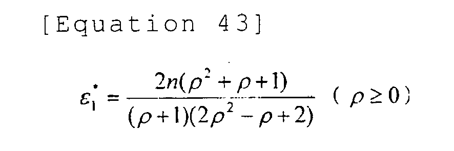
-
Fig. 35 is a flowchart showing steps of a fracture limit obtaining method according to Example 1.
First, the user inputs the material and the mechanical property values (t, YP, TS, El, U.E1, r value, n-th power hardening law/Swift hardening law) of a thin plate. - The
first estimating unit 11 estimates a fracture limit curve in strain space on a proportional loading path based on the mechanical property values inputted by the user (Step S11). - Subsequently, the converting
unit 1 converts the fracture limit curve in strain space estimated by thefirst estimating unit 11 into a fracture limit curve in stress space using the n-th power hardening law/Swift hardening law inputted as the mechanical properties , and for example the Mises' yield function or the like (Step S12).
Subsequently, the fracture limit curve in stress space obtained in step S1 is displayed as a stress FLD on the display unit 2 (step S13). - In addition, the method may also be arranged such that the strain FLD is estimated from a database (t, YP, TS, El, U.E1, r value, strain-stress multiple linear data) of shipping test values, and the stress FLD is calculated from the shipping test values (upper limit value and lower limit value in a quality dispersion distribution within a predetermined standard, and the mean value in the quality dispersion distribution).
- As explained above, according to this example, when determining the fracture limit of a steel sheet in a process including one or more deformation path variations, it is possible to obtain the fracture limit curve easily and efficiently and determine the fracture limit with high prediction accuracy. By this example, the risk of fracture upon press forming or crash can be evaluated quantitatively, thereby enabling efficient and highly precise development of an automobile body optimized the material, the forming, and the body structure.
- Here, a modification example of Example 2 will be explained. In this modification example, as shown in
Fig. 36 , in the fracture limit obtaining device of Example 2, asecond estimating unit 12 is provided instead of thefirst estimating unit 11. - The
second estimating unit 12 estimates the fracture limit curve in strain space on a proportional loading path similarly to thefirst estimating unit 11, and obtains, as described above, a necking occurrence limit in strain space using an approximate equation
second estimating unit 12 identifies, as described above, the material parameter Kc based on one or more measurement values of fracture limit major strain ε1 and fracture limit minor strain ε2. - As explained above, according to this example, better and adequate accuracy can be assured for fracture prediction as compared to Example 2, and the fracture limit curve can be obtained more easily and efficiently, thereby allowing to determine the fracture limit with high prediction accuracy.
- The functions of the respective components (except the display unit 4) constituting the fracture prediction devices according to the above-described examples and the like can be realized by operation of a program product stored in a RAM or ROM of a computer. Similarly, the respective steps of the fracture prediction method and the fracture limit obtaining method (steps S1 to S6 of
Fig. 23 , steps S11 to S14 ofFig. 24 , and so on, steps S1 and S2 ofFig. 33 , steps S11 to S13 ofFig. 35 , and so on) can be realized by operation of a program product stored in a RAM or ROM of a computer. This program product and a computer readable recording medium recording the program product are included in the present invention. - Specifically, the aforementioned program product is provided to a computer by recording in a recording medium such as CD-ROM for example, or by transmitting via various types of transmission media. As the recording medium recording the program product, other than the CD-ROM, it is possible to use a flexible disk, a hard disk, a magnetic tape, a magneto-optical disk, a non-volatile memory card, or the like. On the other hand, as a transmission medium of the program product, a communication medium in a computer network system for supplying program information by propagating as a carrier wave can be used. Here, the computer network is a LAN, a WAN such as the Internet, a radio communication network, or the like, and the communication media is a wired line such as an optic fiber, a wireless line, or the like.
- Further, the program product included in the present invention is not only one such that the functions of the above-described embodiments are realized by a computer executing the supplied program product. For example, when the program product cooperates with the OS (operating system), another application, or the like working on the computer to realize the functions of the above-described embodiments, such a program product is included in the present invention. Furthermore, when all or part of processing of the supplied program product is performed by a function expansion board or a function expansion unit of the computer to realize the functions of the above-described embodiments, such a program product is included in the present invention.
- For example,
Fig. 37 is a schematic diagram showing an internal structure of a personal user terminal device. InFig. 37 , numeral 1200 denotes a personal computer (PC) including aCPU 1201. ThePC 1200 executes device control software which is stored in aROM 1202 or a hard disk (HD) 1211 or supplied by a flexible disk drive (FD) 1212. ThisPC 1200 controls devices connected to asystem bus 1204 in an integrated manner. - By the
CPU 1201 of thePC 1200 and the program product stored in theROM 1202 or the hard disk (HD) 1211, procedures or the like of steps S1 to S6 inFig. 23 of the example and steps S11 to S14 inFig. 24 , steps S1 and S2 ofFig. 33 , steps S11 to S13 ofFig. 35 are realized. -
Numeral 1203 denotes a RAM and functions as a main memory, a work area, or the like for theCPU 1201.Numeral 1205 denotes a keyboard controller (KBC) and controls an instruction input from a keyboard (KB) 1209, a not-shown device, or the like. -
Numeral 1206 denotes a CRT controller (CRTC) and controls display on the CRT display (CRT) 1210.Numeral 1207 denotes a disk controller (DKC). TheDKC 1207 controls access to the hard disk (HD) 1211 storing a boot program, a plurality of applications, edit files, user files, a network administration program, and so on, and to the flexible disk (FD) 1212. Here the boot program is a start-up program, a program starting execution (operation) of hardware and/or software of a personal computer. -
Numeral 1208 denotes a network interface card (NIC) and carries out bidirectional exchange of data via aLAN 1220 with a network printer, another network device, or another PC. - According to the present invention, when predicting presence of fracture occurrence in a thin plate in a process including one or more deformation path variations, it is possible to obtain the fracture limit curve easily and efficiently and predict the presence of fracture occurrence with high prediction accuracy. Thus, the risk of fracture upon press forming or crash can be evaluated quantitatively, thereby realizing efficient and highly precise development of an automobile body optimized the material, the forming, and the body structure.
Claims (22)
- A fracture prediction method evaluating a fracture limit of a thin plate constituted of a metal material, the method comprising, when predicting fracture occurrence in the thin plate in a plastic deformation process according to one or more deformation path variations:a procedure of converting a fracture limit curve in strain space into a fracture limit curve in stress space; anda procedure of predicting presence of the fracture occurrence using the obtained fracture limit curve in stress space.
- The fracture prediction method according to claim 1,
wherein in the procedure of predicting presence of the fracture occurrence, deformation conditions of the thin plate are evaluated by a numerical analysis, an obtained strain is converted into a stress, and the presence of the fracture occurrence is evaluated quantitatively using the fracture limit curve in stress space. - The fracture prediction method according to claim 2,
wherein when predicting fracture occurrence in the thin plate corresponding to each of a plurality of the plastic deformation processes, the deformation conditions of the thin plate evaluated by the numerical analysis in the plastic deformation process in a preceding stage are inherited as initial conditions of the numerical analysis in the plastic deformation process in a succeeding stage. - The fracture prediction method according to claim 3,
wherein the deformation conditions of the thin plate are a thickness of the thin plate and an equivalent plastic strain or the thickness, an equivalent plastic strain, a stress tensor and a strain tensor. - The fracture prediction method according to claim 3 or 4,
wherein the plastic deformation process in the preceding stage is a formation process of the thin plate, and the plastic deformation process in the succeeding stage is a crash process of the thin plate. - The fracture prediction method according to any one of claims 1 to 5,
wherein in the procedure of converting into the fracture limit curve in stress space, the fracture limit curve in strain space is obtained from an experiment. - The fracture prediction method according to any one of claims 1 to 5,
wherein in the procedure of converting into the fracture limit curve in stress space, the fracture limit curve in strain space is estimated theoretically from mechanical property values. - The fracture prediction method according to claim 7,
wherein a necking start line in the strain space is converted into the stress space to obtain the fracture limit curve in stress space. - The fracture prediction method according to claim 1,
wherein in the procedure of predicting the fracture occurrence, a strain obtained from deformation conditions of the thin plate evaluated by an experiment is converted into a stress, and the presence of the fracture occurrence is evaluated quantitatively using the fracture limit curve in stress space. - The fracture prediction method according to any one of claims 2 to 8,
wherein a finite element method is used as a method of the numerical analysis. - The fracture prediction method according to claim 10,
wherein when a dynamic explicit method as one of the finite element methods is used as the method of the numerical analysis, a plastic strain obtained by the dynamic explicit method is converted into a stress and is compared with the fracture limit curve in stress space. - The fracture prediction method according to any one of claims 1 to 8, 10, 11,
wherein in the procedure of predicting the fracture occurrence, the numerical analysis is executed considering speed dependency of a deformation stress of the thin plate, a plastic strain obtained from the numerical analysis is converted to calculate a stress at a reference strain rate, and the stress is compared with the fracture limit curve in stress space corresponding to the reference strain rate. - The fracture prediction method according to any one of claims 1 to 6 and 9 to 12,
wherein fracture prediction of a material is determined using a criterion obtained by converting a hole expansion ratio obtained from a hole expansion test into stress space. - The fracture prediction method according to claim 1,
wherein when converting the fracture limit curve in strain space into the fracture limit curve in stress space, a normality rule of a plastic strain increment in which a plastic strain increment direction is defined in a direction perpendicular to a yield curved surface is used. - The fracture prediction method according to claim 14,
wherein when using the normality rule of the plastic strain increment, a relational expression of an equivalent plastic strain εeq and each strain component εij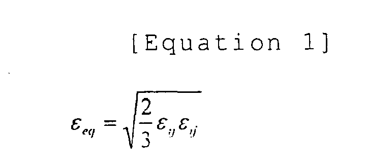
- The fracture prediction method according to any one of claims 1, 14, and 15,
wherein when obtaining the fracture limit curve in strain space on the proportional loading path, after a plurality of in-plane strain ratios regarding the thin plate are obtained by a proportional loading experiment, measurement values of fracture limit major strain ε1 and fracture limit minor strain ε2 in each of the strain ratios are used. - The fracture prediction method according to any one of claims 1, 14, and 15,
wherein when obtaining the fracture limit curve in strain space on the proportional loading path,
a localized necking model
a diffuse necking model
- The fracture prediction method according to any one of claims 1, 14, and 15,
wherein when obtaining the fracture limit curve in strain space on the proportional loading path,
a constitutive equation in which a direction of a plastic strain increment tensor depends on a stress increment tensor as a plastic strain increment law,
a material parameter Kc defining the direction of the plastic strain increment tensor, and
a Storen-Rice localized necking model
are used to obtain a necking occurrence limit in the strain space. - The fracture prediction method according to claim 18,
wherein the material parameter Kc is identified based on one or more measurement values of fracture limit major strain ε1 and fracture limit minor strain ε2. - The fracture prediction method according to claim 17 or 18,
wherein, with the necking occurrence limit being a reference,
a thickness t0 (mm) of the thin plate,
a stress-strain curve obtained from a uniaxial tensile test, and
- The fracture prediction method according to claim 14 or 15,
wherein a stretch strain obtained from a hole expansion test is converted into stress space, and a fracture is determined in the stress space. - The fracture prediction method according to any one of claims 1 to 21,
wherein the thin plate is constituted of a high strength material with tensile strength of 440 MPa (megapascal) class or higher.
Applications Claiming Priority (3)
| Application Number | Priority Date | Filing Date | Title |
|---|---|---|---|
| JP2006024975 | 2006-02-01 | ||
| JP2006024976 | 2006-02-01 | ||
| PCT/JP2007/051711 WO2007088935A1 (en) | 2006-02-01 | 2007-02-01 | Breaking prediction method |
Publications (3)
| Publication Number | Publication Date |
|---|---|
| EP1985989A1 true EP1985989A1 (en) | 2008-10-29 |
| EP1985989A4 EP1985989A4 (en) | 2015-07-08 |
| EP1985989B1 EP1985989B1 (en) | 2021-03-31 |
Family
ID=38327505
Family Applications (1)
| Application Number | Title | Priority Date | Filing Date |
|---|---|---|---|
| EP07707897.0A Active EP1985989B1 (en) | 2006-02-01 | 2007-02-01 | Fracture prediction method |
Country Status (9)
| Country | Link |
|---|---|
| US (1) | US8990028B2 (en) |
| EP (1) | EP1985989B1 (en) |
| KR (1) | KR101065502B1 (en) |
| CN (1) | CN101379381B (en) |
| BR (1) | BRPI0707682B1 (en) |
| CA (1) | CA2641174C (en) |
| MX (1) | MX2008009816A (en) |
| RU (2) | RU2402010C2 (en) |
| WO (1) | WO2007088935A1 (en) |
Cited By (7)
| Publication number | Priority date | Publication date | Assignee | Title |
|---|---|---|---|---|
| CN102466588A (en) * | 2010-11-07 | 2012-05-23 | 山西太钢不锈钢股份有限公司 | A Method for Comparing Interstitial Atom Contents of Metallic Materials |
| EP2543983A4 (en) * | 2010-04-07 | 2013-11-06 | Nippon Steel & Sumitomo Metal Corp | FRACTURE FINDING METHOD, FRACTURE FINDING DEVICE, PROGRAM, AND COMPUTER READABLE RECORDING MEDIUM |
| EP2839896A4 (en) * | 2012-04-16 | 2015-02-25 | Jfe Steel Corp | METHOD FOR TRACING PRESS FORM FORMING LIMIT DIAGRAM, CRACK PREDICTION METHOD, AND METHOD FOR MANUFACTURING COMPRESSED COMPONENTS |
| EP3228399A4 (en) * | 2014-12-02 | 2017-12-27 | JFE Steel Corporation | Methods for evaluating and manufacturing hot-press formed article |
| EP3524959A4 (en) * | 2016-10-05 | 2020-05-20 | Nippon Steel Corporation | FRACTURE DETERMINATION DEVICE, FRACTURE DETERMINATION PROGRAM AND ASSOCIATED METHOD |
| EP3524960A4 (en) * | 2016-10-05 | 2020-05-20 | Nippon Steel Corporation | FRACTURE DETERMINATION DEVICE, FRACTURE DETERMINATION PROGRAM AND ASSOCIATED METHOD |
| EP3939713A4 (en) * | 2019-03-14 | 2022-05-04 | JFE Steel Corporation | STRETCHING FLANGE CRACK ASSESSMENT METHOD, METAL SHEET SELECTION METHOD, PRESS DIE DESIGN METHOD, COMPONENT SHAPE DESIGN METHOD AND PRESSED COMPONENT MANUFACTURING METHOD |
Families Citing this family (86)
| Publication number | Priority date | Publication date | Assignee | Title |
|---|---|---|---|---|
| CN102708222B (en) * | 2006-08-31 | 2014-11-26 | 新日铁住金株式会社 | Method of identification of cause of occurrence of springback, method of identification of location of cause of occurence of springback, method of identification of position of measure against springback, and apparatuses of these |
| US9040865B2 (en) | 2007-02-27 | 2015-05-26 | Exxonmobil Upstream Research Company | Corrosion resistant alloy weldments in carbon steel structures and pipelines to accommodate high axial plastic strains |
| JP4858370B2 (en) * | 2007-09-11 | 2012-01-18 | 住友金属工業株式会社 | Material parameter deriving apparatus and material parameter deriving method |
| JP4935713B2 (en) * | 2008-02-27 | 2012-05-23 | Jfeスチール株式会社 | Method for determining whether molding is possible at the shear edge of a pressed product |
| US8494827B2 (en) * | 2009-09-25 | 2013-07-23 | Exxonmobil Upstream Research Company | Method of predicting natural fractures and damage in a subsurface region |
| US20110295570A1 (en) * | 2010-05-27 | 2011-12-01 | Livermore Software Technology Corporation | Sheet Metal Forming Failure Prediction Using Numerical Simulations |
| CN102004819B (en) * | 2010-11-04 | 2012-10-10 | 西北工业大学 | Method for determining constitutive parameters of butt welded pipe welding seam in biaxial stress state |
| JP5630311B2 (en) * | 2011-02-16 | 2014-11-26 | Jfeスチール株式会社 | Method for predicting cracks in press molding and method for manufacturing pressed parts |
| JP5375941B2 (en) * | 2011-12-21 | 2013-12-25 | Jfeスチール株式会社 | Press molding tool design method, press molding tool |
| DE102012007062B4 (en) * | 2012-04-03 | 2015-07-23 | Fraunhofer-Gesellschaft zur Förderung der angewandten Forschung e.V. | Method for non-destructive quantitative determination of micro-voltage II. And / or III. kind |
| US20140019099A1 (en) * | 2012-07-16 | 2014-01-16 | Livermore Software Technology Corp | Determination Of Failure In Sheet Metal Forming Simulation Using Isotropic Metal Failure Criteria |
| JP5472518B1 (en) * | 2012-11-19 | 2014-04-16 | Jfeスチール株式会社 | Method for determining limit strain of stretch flange and method for determining press forming possibility |
| RU2516592C1 (en) * | 2012-12-17 | 2014-05-20 | Федеральное государственное бюджетное образовательное учреждение высшего профессионального образования "Волгоградский государственный технический университет" (ВолгГТУ) | Method to detect maximum true stresses and deformations |
| JP5644985B1 (en) * | 2013-05-10 | 2014-12-24 | 新日鐵住金株式会社 | Deformation analysis apparatus, deformation analysis method, and program |
| WO2014208697A1 (en) * | 2013-06-26 | 2014-12-31 | 新日鐵住金株式会社 | Method for determining bending fracture in metal plate, program, and storage medium |
| RU2571183C2 (en) * | 2013-07-30 | 2015-12-20 | Открытое акционерное общество "АВТОВАЗ" | Plotting of sheet material limiting strains diagram |
| US10352836B2 (en) | 2014-05-08 | 2019-07-16 | Nippon Steel & Sumitomo Metal Corporation | Evaluation method of plastic material and evaluation method of deformation processing of plastic material |
| US20170108418A1 (en) * | 2014-06-11 | 2017-04-20 | Magna International Inc. | Shifting A Forming Limit Curve Based On Zero Friction Analysis |
| US10372849B2 (en) | 2014-06-11 | 2019-08-06 | Magna International Inc. | Performing and communicating sheet metal simulations employing a combination of factors |
| US11886778B2 (en) * | 2014-06-11 | 2024-01-30 | Magna International Inc. | Shifting a forming limit curve based on zero friction analysis |
| WO2016045024A1 (en) * | 2014-09-25 | 2016-03-31 | 华东理工大学 | Method for measuring and determining fracture toughness of structural material in high-temperature environment |
| RU2591294C1 (en) * | 2015-03-10 | 2016-07-20 | Открытое акционерное общество "АВТОВАЗ" | Method of constructing diagram of limit deformations of sheet material |
| US10732085B2 (en) | 2015-03-24 | 2020-08-04 | Bell Helicopter Textron Inc. | Notch treatment methods for flaw simulation |
| US10989640B2 (en) * | 2015-03-24 | 2021-04-27 | Bell Helicopter Textron Inc. | Method for defining threshold stress curves utilized in fatigue and damage tolerance analysis |
| US20160328503A1 (en) * | 2015-05-06 | 2016-11-10 | Livermore Software Technology Corporation | Methods And Systems For Conducting A Time-Marching Numerical Simulation Of A Structure Expected To Experience Metal Necking Failure |
| JP6098664B2 (en) * | 2015-05-08 | 2017-03-22 | Jfeスチール株式会社 | Shear edge molding availability evaluation method |
| TWI609179B (en) * | 2015-05-18 | 2017-12-21 | 新日鐵住金股份有限公司 | Crack prediction method, program, recording medium, and calculation processing device |
| CN105606448A (en) * | 2015-09-06 | 2016-05-25 | 上海理工大学 | Determination method for fracture toughness of actual cracked structure |
| FR3042592B1 (en) * | 2015-10-16 | 2017-12-01 | Electricite De France | METHOD FOR CONTROLLING CRACKING OF MATERIAL AND DEVICE FOR IMPLEMENTING THE SAME |
| CN106202647B (en) * | 2016-06-29 | 2020-02-21 | 北京科技大学 | Multiaxial fatigue life prediction method and fatigue life reliability evaluation method of electric spindle |
| BR112019017777A2 (en) | 2017-03-16 | 2020-03-31 | Nippon Steel Corporation | METHOD FOR ESTIMATING COLD WORKED HARDNESS AND METHOD FOR ACQUIRING HARDNESS / PLASTIC DEFORMATION CURVE OF STEEL MATERIAL |
| CN108731989B (en) * | 2017-04-24 | 2020-06-02 | 天津大学 | Prediction method of creep incubation period with residual stress under plastic transient creep conditions |
| CN108732033B (en) * | 2017-04-24 | 2020-05-08 | 天津大学 | Creep induction period prediction method considering restraint effect under elastic transient creep condition |
| CN108733860B (en) * | 2017-04-24 | 2020-06-02 | 天津大学 | Prediction method of creep incubation period considering restraint effect under plastic transient creep conditions |
| CN108732034B (en) * | 2017-04-24 | 2020-03-27 | 天津大学 | Prediction method of creep incubation period with residual stress under elastic transient creep conditions |
| CN108732029B (en) * | 2017-04-24 | 2020-02-07 | 天津大学 | Creep induction period prediction method containing residual stress under elastic condition |
| CN108733861B (en) * | 2017-04-24 | 2020-03-27 | 天津大学 | Prediction method of creep incubation period with residual stress under plastic conditions |
| CN108732032B (en) * | 2017-04-24 | 2020-03-27 | 天津大学 | Prediction method of creep incubation period with residual stress under steady-state creep conditions |
| CN108732030B (en) * | 2017-04-24 | 2020-05-08 | 天津大学 | Creep induction period prediction method considering restraint effect under plastic condition |
| CN108732031B (en) * | 2017-04-24 | 2020-06-02 | 天津大学 | Creep induction period prediction method considering restraint effect under elastic condition |
| CN108733862B (en) * | 2017-04-24 | 2020-05-08 | 天津大学 | Prediction method of creep incubation period considering restraint effect under steady-state creep conditions |
| CN107144461B (en) * | 2017-07-05 | 2023-07-14 | 四川大学 | Experimental device for simulating tunnel stress characteristics at faults |
| JP6558515B2 (en) * | 2017-08-23 | 2019-08-14 | Jfeスチール株式会社 | Method for evaluating deformation limit on sheared surface of metal plate, method for predicting cracks, and method for designing press dies |
| CN107907409B (en) * | 2017-11-10 | 2023-01-03 | 中国地质大学(武汉) | Method, equipment and storage equipment for determining rock cracking stress |
| CN109855958B (en) * | 2017-11-30 | 2021-07-06 | 中国科学院金属研究所 | A method for predicting the tensile properties of metallic materials |
| WO2019117288A1 (en) * | 2017-12-15 | 2019-06-20 | 古河電気工業株式会社 | Device and method for screening optical fiber core wire, and method for producing optical fiber core wire |
| CN108051549B (en) * | 2017-12-15 | 2024-03-15 | 中国科学院南京地理与湖泊研究所 | Device and method for measuring critical flow rate of water flow bearable by aquatic plants |
| CN108228992A (en) * | 2017-12-27 | 2018-06-29 | 国网河北省电力公司经济技术研究院 | lightning rod flange design method and terminal device |
| KR102125142B1 (en) * | 2018-09-27 | 2020-07-07 | 한양대학교 에리카산학협력단 | Hole Expansion Device, Hole Expansion Ratio Test Method and Operating Program thereof |
| CN109870362B (en) * | 2019-03-04 | 2020-04-03 | 燕山大学 | A method and system for establishing fracture forming limit diagram of high-strength aluminum alloy sheet |
| CN109948215B (en) * | 2019-03-12 | 2023-02-03 | 本钢板材股份有限公司 | A method for formulating a hot stamping process |
| JP2020159834A (en) * | 2019-03-26 | 2020-10-01 | 日本製鉄株式会社 | Break criteria analysis method, break criteria analysis program, and break criteria analysis system |
| CN110134992B (en) * | 2019-04-08 | 2022-11-18 | 北方工业大学 | A method for judging whether sheet metal forming under complex loading path is absolutely safe |
| CN112560162B (en) * | 2019-09-24 | 2024-05-10 | 上海汽车集团股份有限公司 | Method and device for reducing suspended road spectrum load of power assembly |
| CN110837675B (en) * | 2019-10-31 | 2023-06-06 | 武汉工程大学 | A method, device and system for predicting fracture of a poorly thick plate using an optimized fracture criterion |
| CN112926173B (en) * | 2019-12-06 | 2024-03-01 | 上海梅山钢铁股份有限公司 | A calculation method for the forming limit diagram of hot-rolled high-strength steel plates |
| CN110987621B (en) * | 2019-12-18 | 2023-04-25 | 中国汽车工程研究院股份有限公司 | Method for establishing three-dimensional fracture model of metal material in complex stress state |
| CN111125960B (en) * | 2019-12-26 | 2022-02-22 | 中国汽车工程研究院股份有限公司 | GISSMO material failure model parameter optimization method |
| JP6919742B1 (en) * | 2020-04-07 | 2021-08-18 | Jfeスチール株式会社 | How to identify the constriction limit strain of a metal plate |
| CN111366461B (en) * | 2020-04-13 | 2023-02-03 | 鲁东大学 | Method for testing tensile strength of rock |
| CN111680438A (en) * | 2020-05-15 | 2020-09-18 | 中国第一汽车股份有限公司 | Metal plate stretching experiment data conversion processing method |
| CN111896373B (en) * | 2020-06-30 | 2023-03-24 | 武汉上善仿真科技有限责任公司 | Test and calculation method for determining equivalent plastic strain forming limit diagram |
| CN114112736B (en) * | 2020-08-28 | 2023-11-14 | 宝山钢铁股份有限公司 | Online measuring device and method for determining fracture elongation of low-carbon steel cold-rolled sheet |
| CN112446132B (en) * | 2020-10-19 | 2024-05-28 | 中国石油天然气集团有限公司 | A method for drawing a material full-quadrant fracture forming limit diagram and a method for using the same |
| CN113420388B (en) * | 2021-06-17 | 2022-04-29 | 中铁大桥勘测设计院集团有限公司 | All-welded integral node tearing path calculation method based on fitting Mises yield criterion |
| CN113673030B (en) * | 2021-08-05 | 2023-07-25 | 河钢股份有限公司 | A simulation analysis method for ductile fracture coupled failure of metal materials |
| CN114371078B (en) * | 2022-01-13 | 2024-02-09 | 马鞍山钢铁股份有限公司 | Stamping die acceptance method based on forming safety margin |
| CN114444230B (en) * | 2022-03-04 | 2025-06-20 | 太原理工大学 | A simulation method for deformation and fracture of quasi-brittle materials under supercritical CO2 |
| CN115188437A (en) * | 2022-06-23 | 2022-10-14 | 武汉钢铁有限公司 | Method for determining forming limit of thin plate based on correlation of time and position |
| KR102837695B1 (en) * | 2022-06-30 | 2025-07-24 | 현대제철 주식회사 | Fracture evaluation method of metal plate |
| CN115265323B (en) * | 2022-07-08 | 2024-09-20 | 武汉钢铁有限公司 | Limit flanging height testing method |
| US20240027420A1 (en) * | 2022-07-20 | 2024-01-25 | The Boeing Company | System and method for inspecting components fabricated using a powder metallurgy process |
| CN115326504B (en) * | 2022-07-26 | 2024-06-04 | 燕山大学 | Evaluation method and evaluation device for edge tensile cracking limit of thin steel plate |
| CN117505588A (en) * | 2022-07-29 | 2024-02-06 | 重庆长安汽车股份有限公司 | A multi-dimensional evaluation method and system for material stamping forming performance |
| CN115142160B (en) * | 2022-08-22 | 2023-12-19 | 无锡物联网创新中心有限公司 | Identification method and related device for strong weak ring of yarn |
| CN115488213B (en) * | 2022-09-19 | 2025-11-21 | 首钢集团有限公司 | Prediction method for sheet forming performance |
| CN116167154A (en) * | 2022-12-01 | 2023-05-26 | 奇瑞商用车(安徽)有限公司 | A method and device for preventing vehicle body sheet metal fracture failure based on finite element analysis |
| CN115937294B (en) * | 2022-12-30 | 2023-10-27 | 重庆大学 | Prediction method for goaf caving zone height after coal mine ground fracturing |
| CN116305644A (en) * | 2023-03-17 | 2023-06-23 | 中国汽车技术研究中心有限公司 | Method for evaluating breaking performance of hot stamping part based on forming limit curve |
| CN116933391B (en) * | 2023-07-26 | 2024-01-26 | 广州知元科技有限责任公司 | Stamping information correction method and system for whole vehicle fine collision simulation |
| CN117371272B (en) * | 2023-09-22 | 2024-04-19 | 天津大学 | Calculation method for crack length and fracture properties of clamped single-edge notched tensile specimens with different anisotropic materials and sizes |
| CN117074182B (en) * | 2023-10-17 | 2024-02-02 | 深圳中宝新材科技有限公司 | Method for preventing copper wire breakage self-detection of intelligent bonding copper wire guide stretching device |
| CN119747572B (en) * | 2024-12-26 | 2026-04-03 | 陕西宏远航空锻造有限责任公司 | A forging method for GH4586 high-temperature alloy bladed disks |
| CN119558097B (en) * | 2025-01-24 | 2025-05-13 | 中国科学院力学研究所 | Analysis method for energy-accumulating jet forming and stability |
| CN120293214B (en) * | 2025-04-03 | 2025-12-16 | 京开建设集团有限公司 | Connection quality detection method for connection structure of building outer wall and base |
| CN120869801B (en) * | 2025-09-25 | 2025-12-02 | 西北工业大学 | Electro-assisted biaxial tensile forming limit test system and method for coated sheet materials |
Family Cites Families (18)
| Publication number | Priority date | Publication date | Assignee | Title |
|---|---|---|---|---|
| SU1030647A1 (en) * | 1980-10-03 | 1983-07-23 | Физико-технический институт АН БССР | Device for determining part deformations |
| SU1499162A1 (en) * | 1987-12-08 | 1989-08-07 | Предприятие П/Я М-5671 | Method of testing sheet materials for extension |
| US4852397A (en) * | 1988-01-15 | 1989-08-01 | Haggag Fahmy M | Field indentation microprobe for structural integrity evaluation |
| US5020585A (en) * | 1989-03-20 | 1991-06-04 | Inland Steel Company | Break-out detection in continuous casting |
| SU1656397A1 (en) * | 1989-06-26 | 1991-06-15 | Институт черной металлургии | Method of determination of endurance limit of sheet material |
| JP2546551B2 (en) * | 1991-01-31 | 1996-10-23 | 新日本製鐵株式会社 | γ and β two-phase TiAl-based intermetallic alloy and method for producing the same |
| RU2048227C1 (en) * | 1992-05-26 | 1995-11-20 | Акционерное общество открытого типа "ГАЗ" | Method for stamping flanged body parts |
| DE59600581D1 (en) * | 1995-04-03 | 1998-10-22 | Siemens Ag | DEVICE FOR BREAKTHROUGH DETECTION IN CONTINUOUS CASTING |
| JPH08339396A (en) | 1995-04-12 | 1996-12-24 | Nippon Steel Corp | A processing device for numerical simulation results of deformation process of metal plate. |
| JP3383148B2 (en) * | 1996-04-10 | 2003-03-04 | 新日本製鐵株式会社 | Manufacturing method of high strength steel with excellent toughness |
| US6555182B1 (en) * | 1998-07-03 | 2003-04-29 | Sony Corporation | Surface hardened resins for disk substrates, methods of manufacture thereof and production devices for the manufacture thereof |
| US20020077795A1 (en) * | 2000-09-21 | 2002-06-20 | Woods Joseph Thomas | System, method and storage medium for predicting impact performance of thermoplastic |
| JP3766626B2 (en) * | 2001-11-22 | 2006-04-12 | 新日本製鐵株式会社 | Manufacturing method of high strength steel plate press-formed body |
| WO2003087778A1 (en) * | 2002-04-10 | 2003-10-23 | Mts Systems Corporation | Method and apparatus for determining properties of a test material by scratch testing |
| US7505885B2 (en) * | 2003-01-24 | 2009-03-17 | The Boeing Company | Method and interface elements for finite-element fracture analysis |
| FR2858410B1 (en) * | 2003-07-28 | 2005-09-23 | Electricite De France | METHOD FOR DETERMINING CONSTRAINTS, DEFORMATIONS, DAMAGE TO PARTS CONSISTING OF SOLID MATERIAL |
| JP4421346B2 (en) * | 2004-03-26 | 2010-02-24 | 川崎重工業株式会社 | Ductile fracture limit estimation method, program and recording medium |
| US20080004850A1 (en) * | 2006-06-05 | 2008-01-03 | Phida, Inc. | Method of Universal Formability Analysis in Sheet Metal Forming by Utilizing Finite Element Analysis and Circle Grid Analysis |
-
2007
- 2007-02-01 CN CN2007800041527A patent/CN101379381B/en active Active
- 2007-02-01 CA CA2641174A patent/CA2641174C/en active Active
- 2007-02-01 RU RU2008135325/28A patent/RU2402010C2/en not_active IP Right Cessation
- 2007-02-01 KR KR1020087021077A patent/KR101065502B1/en active Active
- 2007-02-01 EP EP07707897.0A patent/EP1985989B1/en active Active
- 2007-02-01 BR BRPI0707682-7A patent/BRPI0707682B1/en active IP Right Grant
- 2007-02-01 US US12/278,117 patent/US8990028B2/en active Active
- 2007-02-01 WO PCT/JP2007/051711 patent/WO2007088935A1/en not_active Ceased
- 2007-02-01 MX MX2008009816A patent/MX2008009816A/en active IP Right Grant
-
2010
- 2010-03-22 RU RU2010110951/28A patent/RU2434217C1/en not_active IP Right Cessation
Non-Patent Citations (1)
| Title |
|---|
| See references of WO2007088935A1 * |
Cited By (11)
| Publication number | Priority date | Publication date | Assignee | Title |
|---|---|---|---|---|
| EP2543983A4 (en) * | 2010-04-07 | 2013-11-06 | Nippon Steel & Sumitomo Metal Corp | FRACTURE FINDING METHOD, FRACTURE FINDING DEVICE, PROGRAM, AND COMPUTER READABLE RECORDING MEDIUM |
| US8606532B2 (en) | 2010-04-07 | 2013-12-10 | Nippon Steel & Sumitomo Metal Corporation | Fracture determination method, fracture determination apparatus, program, and computer readable recording medium |
| EP3023764A1 (en) * | 2010-04-07 | 2016-05-25 | Nippon Steel & Sumitomo Metal Corporation | Fracture determination method, fracture determination apparatus, program, and computer readable recording medium |
| CN102466588A (en) * | 2010-11-07 | 2012-05-23 | 山西太钢不锈钢股份有限公司 | A Method for Comparing Interstitial Atom Contents of Metallic Materials |
| CN102466588B (en) * | 2010-11-07 | 2013-06-12 | 山西太钢不锈钢股份有限公司 | Method for comparing contents of interstitial atoms of metal materials |
| EP2839896A4 (en) * | 2012-04-16 | 2015-02-25 | Jfe Steel Corp | METHOD FOR TRACING PRESS FORM FORMING LIMIT DIAGRAM, CRACK PREDICTION METHOD, AND METHOD FOR MANUFACTURING COMPRESSED COMPONENTS |
| EP3228399A4 (en) * | 2014-12-02 | 2017-12-27 | JFE Steel Corporation | Methods for evaluating and manufacturing hot-press formed article |
| EP3524959A4 (en) * | 2016-10-05 | 2020-05-20 | Nippon Steel Corporation | FRACTURE DETERMINATION DEVICE, FRACTURE DETERMINATION PROGRAM AND ASSOCIATED METHOD |
| EP3524960A4 (en) * | 2016-10-05 | 2020-05-20 | Nippon Steel Corporation | FRACTURE DETERMINATION DEVICE, FRACTURE DETERMINATION PROGRAM AND ASSOCIATED METHOD |
| EP3939713A4 (en) * | 2019-03-14 | 2022-05-04 | JFE Steel Corporation | STRETCHING FLANGE CRACK ASSESSMENT METHOD, METAL SHEET SELECTION METHOD, PRESS DIE DESIGN METHOD, COMPONENT SHAPE DESIGN METHOD AND PRESSED COMPONENT MANUFACTURING METHOD |
| US11971390B2 (en) | 2019-03-14 | 2024-04-30 | Jfe Steel Corporation | Stretch flange crack evaluation method, metal sheet selection method, press die design method, component shape design method, and pressed component manufacturing method |
Also Published As
| Publication number | Publication date |
|---|---|
| BRPI0707682B1 (en) | 2023-01-10 |
| RU2010110951A (en) | 2011-09-27 |
| CN101379381B (en) | 2012-08-22 |
| KR20080090551A (en) | 2008-10-08 |
| RU2434217C1 (en) | 2011-11-20 |
| BRPI0707682A2 (en) | 2011-05-10 |
| MX2008009816A (en) | 2008-09-11 |
| EP1985989A4 (en) | 2015-07-08 |
| KR101065502B1 (en) | 2011-09-19 |
| US8990028B2 (en) | 2015-03-24 |
| CA2641174A1 (en) | 2007-08-09 |
| US20090177417A1 (en) | 2009-07-09 |
| CN101379381A (en) | 2009-03-04 |
| EP1985989B1 (en) | 2021-03-31 |
| WO2007088935A1 (en) | 2007-08-09 |
| RU2008135325A (en) | 2010-03-10 |
| CA2641174C (en) | 2014-03-04 |
| RU2402010C2 (en) | 2010-10-20 |
Similar Documents
| Publication | Publication Date | Title |
|---|---|---|
| EP1985989B1 (en) | Fracture prediction method | |
| JP4621217B2 (en) | Fracture prediction method and apparatus, program, and recording medium | |
| JP4621216B2 (en) | Fracture limit acquisition method and apparatus, program, and recording medium | |
| EP2543983B1 (en) | Method of assessing fractures, fracture assessment device, program and computer readable recording medium | |
| EP3016009B1 (en) | Method for determining bending fracture in metal plate, program, and storage medium | |
| EP2136197B1 (en) | Breakage prediction method, calculation processing device, program, and recording medium | |
| Yilamu et al. | Air bending and springback of stainless steel clad aluminum sheet | |
| JP5445381B2 (en) | Method and apparatus for predicting bending fracture of material, program, and recording medium | |
| JP2017142793A (en) | Prediction method of edge part rupture, program and recording media | |
| JP4818786B2 (en) | Fracture limit acquisition system and method, fracture prediction system and method, program and recording medium for these methods | |
| WO2020170496A1 (en) | Method for estimating stress-strain relationship | |
| JP7110976B2 (en) | Formability evaluation method, program and recording medium | |
| CN104755187B (en) | Springback capacity evaluation methodology | |
| JP7206902B2 (en) | Formability evaluation method, program and recording medium | |
| Nguyen et al. | A numerical and experimental study on the hold-edge conditions and hole-expansion ratio of hole-blanking and hole-expansion tests for ferrite bainite steel (FB590) sheets | |
| Amirabdollahian et al. | Improving the Performance of the Quadratic Hill’s Yield Criterion Considering the Evolution of Plastic Anisotropy Based on the Image Processing Correlation and Numerical Modeling | |
| Xiao et al. | Application and comparison of different anisotropic yield criteria in the formability analysis of aluminum sheet | |
| Ramadoss et al. | Finite element simulation of forming limit diagram for AISI 316LN Austenitic stainless steel |
Legal Events
| Date | Code | Title | Description |
|---|---|---|---|
| PUAI | Public reference made under article 153(3) epc to a published international application that has entered the european phase |
Free format text: ORIGINAL CODE: 0009012 |
|
| 17P | Request for examination filed |
Effective date: 20080828 |
|
| AK | Designated contracting states |
Kind code of ref document: A1 Designated state(s): AT BE BG CH CY CZ DE DK EE ES FI FR GB GR HU IE IS IT LI LT LU LV MC NL PL PT RO SE SI SK TR |
|
| DAX | Request for extension of the european patent (deleted) | ||
| RAP1 | Party data changed (applicant data changed or rights of an application transferred) |
Owner name: NIPPON STEEL & SUMITOMO METAL CORPORATION |
|
| RA4 | Supplementary search report drawn up and despatched (corrected) |
Effective date: 20150610 |
|
| RIC1 | Information provided on ipc code assigned before grant |
Ipc: G06F 17/50 20060101ALI20150604BHEP Ipc: G01N 3/00 20060101AFI20150604BHEP |
|
| RAP1 | Party data changed (applicant data changed or rights of an application transferred) |
Owner name: NIPPON STEEL CORPORATION |
|
| STAA | Information on the status of an ep patent application or granted ep patent |
Free format text: STATUS: EXAMINATION IS IN PROGRESS |
|
| 17Q | First examination report despatched |
Effective date: 20191217 |
|
| REG | Reference to a national code |
Ref country code: DE Ref legal event code: R079 Ref document number: 602007061017 Country of ref document: DE Free format text: PREVIOUS MAIN CLASS: G01N0003000000 Ipc: G06F0030150000 |
|
| GRAP | Despatch of communication of intention to grant a patent |
Free format text: ORIGINAL CODE: EPIDOSNIGR1 |
|
| STAA | Information on the status of an ep patent application or granted ep patent |
Free format text: STATUS: GRANT OF PATENT IS INTENDED |
|
| RIC1 | Information provided on ipc code assigned before grant |
Ipc: G06F 30/23 20200101ALI20200331BHEP Ipc: G01N 3/00 20060101ALI20200331BHEP Ipc: G06F 30/15 20200101AFI20200331BHEP |
|
| INTG | Intention to grant announced |
Effective date: 20200422 |
|
| GRAJ | Information related to disapproval of communication of intention to grant by the applicant or resumption of examination proceedings by the epo deleted |
Free format text: ORIGINAL CODE: EPIDOSDIGR1 |
|
| STAA | Information on the status of an ep patent application or granted ep patent |
Free format text: STATUS: EXAMINATION IS IN PROGRESS |
|
| INTC | Intention to grant announced (deleted) | ||
| GRAP | Despatch of communication of intention to grant a patent |
Free format text: ORIGINAL CODE: EPIDOSNIGR1 |
|
| STAA | Information on the status of an ep patent application or granted ep patent |
Free format text: STATUS: GRANT OF PATENT IS INTENDED |
|
| INTG | Intention to grant announced |
Effective date: 20200923 |
|
| GRAS | Grant fee paid |
Free format text: ORIGINAL CODE: EPIDOSNIGR3 |
|
| GRAL | Information related to payment of fee for publishing/printing deleted |
Free format text: ORIGINAL CODE: EPIDOSDIGR3 |
|
| GRAS | Grant fee paid |
Free format text: ORIGINAL CODE: EPIDOSNIGR3 |
|
| GRAA | (expected) grant |
Free format text: ORIGINAL CODE: 0009210 |
|
| STAA | Information on the status of an ep patent application or granted ep patent |
Free format text: STATUS: THE PATENT HAS BEEN GRANTED |
|
| AK | Designated contracting states |
Kind code of ref document: B1 Designated state(s): AT BE BG CH CY CZ DE DK EE ES FI FR GB GR HU IE IS IT LI LT LU LV MC NL PL PT RO SE SI SK TR |
|
| REG | Reference to a national code |
Ref country code: GB Ref legal event code: FG4D Ref country code: CH Ref legal event code: EP |
|
| REG | Reference to a national code |
Ref country code: DE Ref legal event code: R096 Ref document number: 602007061017 Country of ref document: DE Ref country code: AT Ref legal event code: REF Ref document number: 1377752 Country of ref document: AT Kind code of ref document: T Effective date: 20210415 |
|
| REG | Reference to a national code |
Ref country code: IE Ref legal event code: FG4D |
|
| REG | Reference to a national code |
Ref country code: LT Ref legal event code: MG9D |
|
| PG25 | Lapsed in a contracting state [announced via postgrant information from national office to epo] |
Ref country code: BG Free format text: LAPSE BECAUSE OF FAILURE TO SUBMIT A TRANSLATION OF THE DESCRIPTION OR TO PAY THE FEE WITHIN THE PRESCRIBED TIME-LIMIT Effective date: 20210630 Ref country code: FI Free format text: LAPSE BECAUSE OF FAILURE TO SUBMIT A TRANSLATION OF THE DESCRIPTION OR TO PAY THE FEE WITHIN THE PRESCRIBED TIME-LIMIT Effective date: 20210331 |
|
| PG25 | Lapsed in a contracting state [announced via postgrant information from national office to epo] |
Ref country code: SE Free format text: LAPSE BECAUSE OF FAILURE TO SUBMIT A TRANSLATION OF THE DESCRIPTION OR TO PAY THE FEE WITHIN THE PRESCRIBED TIME-LIMIT Effective date: 20210331 Ref country code: LV Free format text: LAPSE BECAUSE OF FAILURE TO SUBMIT A TRANSLATION OF THE DESCRIPTION OR TO PAY THE FEE WITHIN THE PRESCRIBED TIME-LIMIT Effective date: 20210331 |
|
| REG | Reference to a national code |
Ref country code: NL Ref legal event code: MP Effective date: 20210331 |
|
| REG | Reference to a national code |
Ref country code: AT Ref legal event code: MK05 Ref document number: 1377752 Country of ref document: AT Kind code of ref document: T Effective date: 20210331 |
|
| PG25 | Lapsed in a contracting state [announced via postgrant information from national office to epo] |
Ref country code: EE Free format text: LAPSE BECAUSE OF FAILURE TO SUBMIT A TRANSLATION OF THE DESCRIPTION OR TO PAY THE FEE WITHIN THE PRESCRIBED TIME-LIMIT Effective date: 20210331 Ref country code: CZ Free format text: LAPSE BECAUSE OF FAILURE TO SUBMIT A TRANSLATION OF THE DESCRIPTION OR TO PAY THE FEE WITHIN THE PRESCRIBED TIME-LIMIT Effective date: 20210331 Ref country code: NL Free format text: LAPSE BECAUSE OF FAILURE TO SUBMIT A TRANSLATION OF THE DESCRIPTION OR TO PAY THE FEE WITHIN THE PRESCRIBED TIME-LIMIT Effective date: 20210331 Ref country code: LT Free format text: LAPSE BECAUSE OF FAILURE TO SUBMIT A TRANSLATION OF THE DESCRIPTION OR TO PAY THE FEE WITHIN THE PRESCRIBED TIME-LIMIT Effective date: 20210331 Ref country code: AT Free format text: LAPSE BECAUSE OF FAILURE TO SUBMIT A TRANSLATION OF THE DESCRIPTION OR TO PAY THE FEE WITHIN THE PRESCRIBED TIME-LIMIT Effective date: 20210331 |
|
| PG25 | Lapsed in a contracting state [announced via postgrant information from national office to epo] |
Ref country code: SK Free format text: LAPSE BECAUSE OF FAILURE TO SUBMIT A TRANSLATION OF THE DESCRIPTION OR TO PAY THE FEE WITHIN THE PRESCRIBED TIME-LIMIT Effective date: 20210331 Ref country code: PT Free format text: LAPSE BECAUSE OF FAILURE TO SUBMIT A TRANSLATION OF THE DESCRIPTION OR TO PAY THE FEE WITHIN THE PRESCRIBED TIME-LIMIT Effective date: 20210802 Ref country code: PL Free format text: LAPSE BECAUSE OF FAILURE TO SUBMIT A TRANSLATION OF THE DESCRIPTION OR TO PAY THE FEE WITHIN THE PRESCRIBED TIME-LIMIT Effective date: 20210331 Ref country code: ES Free format text: LAPSE BECAUSE OF FAILURE TO SUBMIT A TRANSLATION OF THE DESCRIPTION OR TO PAY THE FEE WITHIN THE PRESCRIBED TIME-LIMIT Effective date: 20210331 Ref country code: IS Free format text: LAPSE BECAUSE OF FAILURE TO SUBMIT A TRANSLATION OF THE DESCRIPTION OR TO PAY THE FEE WITHIN THE PRESCRIBED TIME-LIMIT Effective date: 20210731 Ref country code: RO Free format text: LAPSE BECAUSE OF FAILURE TO SUBMIT A TRANSLATION OF THE DESCRIPTION OR TO PAY THE FEE WITHIN THE PRESCRIBED TIME-LIMIT Effective date: 20210331 |
|
| REG | Reference to a national code |
Ref country code: DE Ref legal event code: R097 Ref document number: 602007061017 Country of ref document: DE |
|
| PG25 | Lapsed in a contracting state [announced via postgrant information from national office to epo] |
Ref country code: DK Free format text: LAPSE BECAUSE OF FAILURE TO SUBMIT A TRANSLATION OF THE DESCRIPTION OR TO PAY THE FEE WITHIN THE PRESCRIBED TIME-LIMIT Effective date: 20210331 |
|
| PLBE | No opposition filed within time limit |
Free format text: ORIGINAL CODE: 0009261 |
|
| STAA | Information on the status of an ep patent application or granted ep patent |
Free format text: STATUS: NO OPPOSITION FILED WITHIN TIME LIMIT |
|
| 26N | No opposition filed |
Effective date: 20220104 |
|
| PG25 | Lapsed in a contracting state [announced via postgrant information from national office to epo] |
Ref country code: IS Free format text: LAPSE BECAUSE OF FAILURE TO SUBMIT A TRANSLATION OF THE DESCRIPTION OR TO PAY THE FEE WITHIN THE PRESCRIBED TIME-LIMIT Effective date: 20210731 |
|
| PG25 | Lapsed in a contracting state [announced via postgrant information from national office to epo] |
Ref country code: IT Free format text: LAPSE BECAUSE OF FAILURE TO SUBMIT A TRANSLATION OF THE DESCRIPTION OR TO PAY THE FEE WITHIN THE PRESCRIBED TIME-LIMIT Effective date: 20210331 |
|
| PG25 | Lapsed in a contracting state [announced via postgrant information from national office to epo] |
Ref country code: MC Free format text: LAPSE BECAUSE OF FAILURE TO SUBMIT A TRANSLATION OF THE DESCRIPTION OR TO PAY THE FEE WITHIN THE PRESCRIBED TIME-LIMIT Effective date: 20210331 |
|
| REG | Reference to a national code |
Ref country code: CH Ref legal event code: PL |
|
| REG | Reference to a national code |
Ref country code: BE Ref legal event code: MM Effective date: 20220228 |
|
| GBPC | Gb: european patent ceased through non-payment of renewal fee |
Effective date: 20220201 |
|
| PG25 | Lapsed in a contracting state [announced via postgrant information from national office to epo] |
Ref country code: LU Free format text: LAPSE BECAUSE OF NON-PAYMENT OF DUE FEES Effective date: 20220201 |
|
| PG25 | Lapsed in a contracting state [announced via postgrant information from national office to epo] |
Ref country code: LI Free format text: LAPSE BECAUSE OF NON-PAYMENT OF DUE FEES Effective date: 20220228 Ref country code: IE Free format text: LAPSE BECAUSE OF NON-PAYMENT OF DUE FEES Effective date: 20220201 Ref country code: GB Free format text: LAPSE BECAUSE OF NON-PAYMENT OF DUE FEES Effective date: 20220201 Ref country code: CH Free format text: LAPSE BECAUSE OF NON-PAYMENT OF DUE FEES Effective date: 20220228 |
|
| PG25 | Lapsed in a contracting state [announced via postgrant information from national office to epo] |
Ref country code: BE Free format text: LAPSE BECAUSE OF NON-PAYMENT OF DUE FEES Effective date: 20220228 |
|
| PG25 | Lapsed in a contracting state [announced via postgrant information from national office to epo] |
Ref country code: HU Free format text: LAPSE BECAUSE OF FAILURE TO SUBMIT A TRANSLATION OF THE DESCRIPTION OR TO PAY THE FEE WITHIN THE PRESCRIBED TIME-LIMIT; INVALID AB INITIO Effective date: 20070201 |
|
| PG25 | Lapsed in a contracting state [announced via postgrant information from national office to epo] |
Ref country code: CY Free format text: LAPSE BECAUSE OF FAILURE TO SUBMIT A TRANSLATION OF THE DESCRIPTION OR TO PAY THE FEE WITHIN THE PRESCRIBED TIME-LIMIT Effective date: 20210331 |
|
| PG25 | Lapsed in a contracting state [announced via postgrant information from national office to epo] |
Ref country code: TR Free format text: LAPSE BECAUSE OF FAILURE TO SUBMIT A TRANSLATION OF THE DESCRIPTION OR TO PAY THE FEE WITHIN THE PRESCRIBED TIME-LIMIT Effective date: 20210331 |
|
| PG25 | Lapsed in a contracting state [announced via postgrant information from national office to epo] |
Ref country code: GR Free format text: LAPSE BECAUSE OF NON-PAYMENT OF DUE FEES Effective date: 20210331 |
|
| PG25 | Lapsed in a contracting state [announced via postgrant information from national office to epo] |
Ref country code: GR Free format text: LAPSE BECAUSE OF NON-PAYMENT OF DUE FEES Effective date: 20210331 |
|
| PGFP | Annual fee paid to national office [announced via postgrant information from national office to epo] |
Ref country code: FR Payment date: 20241231 Year of fee payment: 19 |
|
| PGFP | Annual fee paid to national office [announced via postgrant information from national office to epo] |
Ref country code: DE Payment date: 20241231 Year of fee payment: 19 |