EP1985833A2 - Fuel injection control system of internal combustion engine - Google Patents
Fuel injection control system of internal combustion engine Download PDFInfo
- Publication number
- EP1985833A2 EP1985833A2 EP08007937A EP08007937A EP1985833A2 EP 1985833 A2 EP1985833 A2 EP 1985833A2 EP 08007937 A EP08007937 A EP 08007937A EP 08007937 A EP08007937 A EP 08007937A EP 1985833 A2 EP1985833 A2 EP 1985833A2
- Authority
- EP
- European Patent Office
- Prior art keywords
- fuel
- amount
- temperature
- air intake
- computing
- Prior art date
- Legal status (The legal status is an assumption and is not a legal conclusion. Google has not performed a legal analysis and makes no representation as to the accuracy of the status listed.)
- Withdrawn
Links
- 239000000446 fuel Substances 0.000 title claims abstract description 608
- 238000002347 injection Methods 0.000 title claims description 64
- 239000007924 injection Substances 0.000 title claims description 64
- 238000002485 combustion reaction Methods 0.000 title claims description 51
- 238000001704 evaporation Methods 0.000 claims abstract description 60
- 230000008020 evaporation Effects 0.000 claims abstract description 60
- 238000012937 correction Methods 0.000 claims description 73
- XLYOFNOQVPJJNP-UHFFFAOYSA-N water Substances O XLYOFNOQVPJJNP-UHFFFAOYSA-N 0.000 claims description 46
- 230000005540 biological transmission Effects 0.000 claims description 9
- 239000000498 cooling water Substances 0.000 claims description 8
- 230000007704 transition Effects 0.000 abstract description 8
- 230000014509 gene expression Effects 0.000 description 19
- 238000004364 calculation method Methods 0.000 description 15
- 230000008859 change Effects 0.000 description 13
- 230000006399 behavior Effects 0.000 description 11
- 230000000630 rising effect Effects 0.000 description 11
- QVGXLLKOCUKJST-UHFFFAOYSA-N atomic oxygen Chemical compound [O] QVGXLLKOCUKJST-UHFFFAOYSA-N 0.000 description 7
- 238000010586 diagram Methods 0.000 description 7
- 239000001301 oxygen Substances 0.000 description 7
- 229910052760 oxygen Inorganic materials 0.000 description 7
- 239000007789 gas Substances 0.000 description 6
- 230000001133 acceleration Effects 0.000 description 3
- 238000012545 processing Methods 0.000 description 3
- 238000010792 warming Methods 0.000 description 3
- 238000007796 conventional method Methods 0.000 description 2
- 238000000034 method Methods 0.000 description 2
- 239000000203 mixture Substances 0.000 description 2
- 230000002159 abnormal effect Effects 0.000 description 1
- 238000004590 computer program Methods 0.000 description 1
- 238000004880 explosion Methods 0.000 description 1
- 230000010354 integration Effects 0.000 description 1
- 238000012986 modification Methods 0.000 description 1
- 230000004048 modification Effects 0.000 description 1
- 230000008569 process Effects 0.000 description 1
- 230000009467 reduction Effects 0.000 description 1
- 230000001360 synchronised effect Effects 0.000 description 1
Images






Classifications
-
- F—MECHANICAL ENGINEERING; LIGHTING; HEATING; WEAPONS; BLASTING
- F02—COMBUSTION ENGINES; HOT-GAS OR COMBUSTION-PRODUCT ENGINE PLANTS
- F02D—CONTROLLING COMBUSTION ENGINES
- F02D41/00—Electrical control of supply of combustible mixture or its constituents
- F02D41/02—Circuit arrangements for generating control signals
- F02D41/04—Introducing corrections for particular operating conditions
- F02D41/047—Taking into account fuel evaporation or wall wetting
-
- F—MECHANICAL ENGINEERING; LIGHTING; HEATING; WEAPONS; BLASTING
- F02—COMBUSTION ENGINES; HOT-GAS OR COMBUSTION-PRODUCT ENGINE PLANTS
- F02D—CONTROLLING COMBUSTION ENGINES
- F02D41/00—Electrical control of supply of combustible mixture or its constituents
- F02D41/02—Circuit arrangements for generating control signals
- F02D41/04—Introducing corrections for particular operating conditions
- F02D41/10—Introducing corrections for particular operating conditions for acceleration
- F02D41/107—Introducing corrections for particular operating conditions for acceleration and deceleration
-
- F—MECHANICAL ENGINEERING; LIGHTING; HEATING; WEAPONS; BLASTING
- F02—COMBUSTION ENGINES; HOT-GAS OR COMBUSTION-PRODUCT ENGINE PLANTS
- F02D—CONTROLLING COMBUSTION ENGINES
- F02D41/00—Electrical control of supply of combustible mixture or its constituents
- F02D41/30—Controlling fuel injection
- F02D41/32—Controlling fuel injection of the low pressure type
- F02D41/34—Controlling fuel injection of the low pressure type with means for controlling injection timing or duration
-
- F—MECHANICAL ENGINEERING; LIGHTING; HEATING; WEAPONS; BLASTING
- F02—COMBUSTION ENGINES; HOT-GAS OR COMBUSTION-PRODUCT ENGINE PLANTS
- F02D—CONTROLLING COMBUSTION ENGINES
- F02D2200/00—Input parameters for engine control
- F02D2200/02—Input parameters for engine control the parameters being related to the engine
- F02D2200/021—Engine temperature
-
- F—MECHANICAL ENGINEERING; LIGHTING; HEATING; WEAPONS; BLASTING
- F02—COMBUSTION ENGINES; HOT-GAS OR COMBUSTION-PRODUCT ENGINE PLANTS
- F02D—CONTROLLING COMBUSTION ENGINES
- F02D2200/00—Input parameters for engine control
- F02D2200/02—Input parameters for engine control the parameters being related to the engine
- F02D2200/04—Engine intake system parameters
- F02D2200/0406—Intake manifold pressure
-
- F—MECHANICAL ENGINEERING; LIGHTING; HEATING; WEAPONS; BLASTING
- F02—COMBUSTION ENGINES; HOT-GAS OR COMBUSTION-PRODUCT ENGINE PLANTS
- F02D—CONTROLLING COMBUSTION ENGINES
- F02D2200/00—Input parameters for engine control
- F02D2200/02—Input parameters for engine control the parameters being related to the engine
- F02D2200/04—Engine intake system parameters
- F02D2200/0414—Air temperature
-
- F—MECHANICAL ENGINEERING; LIGHTING; HEATING; WEAPONS; BLASTING
- F02—COMBUSTION ENGINES; HOT-GAS OR COMBUSTION-PRODUCT ENGINE PLANTS
- F02D—CONTROLLING COMBUSTION ENGINES
- F02D2200/00—Input parameters for engine control
- F02D2200/02—Input parameters for engine control the parameters being related to the engine
- F02D2200/06—Fuel or fuel supply system parameters
- F02D2200/0606—Fuel temperature
-
- F—MECHANICAL ENGINEERING; LIGHTING; HEATING; WEAPONS; BLASTING
- F02—COMBUSTION ENGINES; HOT-GAS OR COMBUSTION-PRODUCT ENGINE PLANTS
- F02D—CONTROLLING COMBUSTION ENGINES
- F02D2200/00—Input parameters for engine control
- F02D2200/02—Input parameters for engine control the parameters being related to the engine
- F02D2200/06—Fuel or fuel supply system parameters
- F02D2200/0611—Fuel type, fuel composition or fuel quality
- F02D2200/0612—Fuel type, fuel composition or fuel quality determined by estimation
-
- F—MECHANICAL ENGINEERING; LIGHTING; HEATING; WEAPONS; BLASTING
- F02—COMBUSTION ENGINES; HOT-GAS OR COMBUSTION-PRODUCT ENGINE PLANTS
- F02D—CONTROLLING COMBUSTION ENGINES
- F02D41/00—Electrical control of supply of combustible mixture or its constituents
- F02D41/0002—Controlling intake air
-
- F—MECHANICAL ENGINEERING; LIGHTING; HEATING; WEAPONS; BLASTING
- F02—COMBUSTION ENGINES; HOT-GAS OR COMBUSTION-PRODUCT ENGINE PLANTS
- F02D—CONTROLLING COMBUSTION ENGINES
- F02D41/00—Electrical control of supply of combustible mixture or its constituents
- F02D41/02—Circuit arrangements for generating control signals
- F02D41/14—Introducing closed-loop corrections
- F02D41/1438—Introducing closed-loop corrections using means for determining characteristics of the combustion gases; Sensors therefor
- F02D41/1444—Introducing closed-loop corrections using means for determining characteristics of the combustion gases; Sensors therefor characterised by the characteristics of the combustion gases
- F02D41/1454—Introducing closed-loop corrections using means for determining characteristics of the combustion gases; Sensors therefor characterised by the characteristics of the combustion gases the characteristics being an oxygen content or concentration or the air-fuel ratio
-
- F—MECHANICAL ENGINEERING; LIGHTING; HEATING; WEAPONS; BLASTING
- F02—COMBUSTION ENGINES; HOT-GAS OR COMBUSTION-PRODUCT ENGINE PLANTS
- F02P—IGNITION, OTHER THAN COMPRESSION IGNITION, FOR INTERNAL-COMBUSTION ENGINES; TESTING OF IGNITION TIMING IN COMPRESSION-IGNITION ENGINES
- F02P5/00—Advancing or retarding ignition; Control therefor
- F02P5/04—Advancing or retarding ignition; Control therefor automatically, as a function of the working conditions of the engine or vehicle or of the atmospheric conditions
- F02P5/145—Advancing or retarding ignition; Control therefor automatically, as a function of the working conditions of the engine or vehicle or of the atmospheric conditions using electrical means
- F02P5/15—Digital data processing
- F02P5/1502—Digital data processing using one central computing unit
-
- Y—GENERAL TAGGING OF NEW TECHNOLOGICAL DEVELOPMENTS; GENERAL TAGGING OF CROSS-SECTIONAL TECHNOLOGIES SPANNING OVER SEVERAL SECTIONS OF THE IPC; TECHNICAL SUBJECTS COVERED BY FORMER USPC CROSS-REFERENCE ART COLLECTIONS [XRACs] AND DIGESTS
- Y02—TECHNOLOGIES OR APPLICATIONS FOR MITIGATION OR ADAPTATION AGAINST CLIMATE CHANGE
- Y02T—CLIMATE CHANGE MITIGATION TECHNOLOGIES RELATED TO TRANSPORTATION
- Y02T10/00—Road transport of goods or passengers
- Y02T10/10—Internal combustion engine [ICE] based vehicles
- Y02T10/40—Engine management systems
Definitions
- the present invention relates to a fuel control system of an internal combustion engine, and more particularly to a fuel control system of an internal combustion engine which can precisely achieve an air-fuel ratio control precision in each of operating ranges of the internal combustion engine, in detail, a demanded air fuel ratio at a time of an engine transition period.
- a fuel control apparatus of an internal combustion engine there is a structure which stores a balanced adhering amount of a fuel film with respect to a cooling water temperature of an internal combustion engine (an engine), determines a base fuel film correction amount with respect to a base fuel, further prepares an air intake valve predictive temperature, determines an engine temperature unbalanced state such as a warming up or the like in the case that a difference exists between the cooling water temperature and the air intake valve predictive temperature, calculates a fuel film correction amount of the temperature unbalanced state in correspondence to the temperature difference, and adds to the base fuel film correction amount so as to correct (for example, patent document 1 ( JP-B2-3562026 )).
- the conventional method mentioned above takes into consideration the temperature transition period of the engine such as the warming up or the like, however, does not take into consideration a macroscopic temperature change in a place to which the fuel film is actually adhered.
- the conventional method there is no difference between a cooling water temperature and an air intake valve predictive temperature after the warming up, and the temperature balanced state is determined. Thereafter, the fuel is only corrected on the basis of the change of the balanced fuel film amount in accordance with the region. In other words, the same amount of correction is always applied in the repeat of the transition under the same condition.
- the temperature at the position to which the fuel film is adhered is changed before and after the transition, on the basis of a heat quantity of the fuel, a heat transmission from the air intake valve, and a heat quantity absorbed by the intake air amount, the adhesion of the fuel, and an evaporation from the fuel film are differentiated in accordance with the change of the temperature, and the fuel film amount is also changed.
- the repeat of the transition under the same condition in order to achieve the demanded air fuel ratio, it is necessary to carry out the correction in correspondence to the fuel film amount change in accordance with the heat quantity change.
- the present invention is made by taking the problem to be solved into consideration, and an object of the present invention is to provide a fuel control system which can achieve an air fuel ratio control precision in each of operating regions of an engine, particularly precisely achieve a demand air fuel ratio at a time of an engine transition.
- a fuel control system of an internal combustion engine comprising:
- a fuel control system of an internal combustion engine comprising:
- the balance of the applied heat quantity and the absorbed heat quantity includes a heat quantity near the air intake valve.
- the heat quantity near the valve is computed by a heat quantity transmission rate of the temperature near the valve determined on the basis of the temperature near the valve and the intake air amount of the internal combustion engine from an integrated value of the intake air amount of the internal combustion engine.
- the balance of the applied heat quantity and the absorbed heat quantity includes a heat quantity of the intake air amount of the internal combustion engine.
- the balance of the applied heat quantity and the absorbed heat quantity includes a heat quantity of the fuel.
- the balance of the applied heat quantity and the absorbed heat quantity includes a heat quantity of an engine cooling water.
- the air intake manifold wall temperature estimating means has a means for storing a predetermined temperature width with respect to the result of comparison, a means for deciding a reaching temperature to any one of an engine water temperature near the adhered position and the temperature near the air intake valve on the basis of the result of comparison, and a means for approximating to the decided reaching temperature in increments of the predetermined temperature width.
- the predetermined temperature width with respect to the result of comparison is constituted by a stored parameter group stored in correspondence to a magnitude of the result of comparison.
- the structure is made such as to estimate the temperature (the air intake manifold wall temperature) of the position to which the fuel is adhered by the heat quantity balance applied to the already adhered fuel (the air intake manifold wall temperature), and decide the adhesion rate of the fuel and the evaporation rate from the fuel film from the air intake manifold wall temperature.
- the structure is made such as to determine the fuel temperature estimated value and the valve temperature estimated value in such a manner that the upper and lower limit values can be set, and change the air intake manifold wall temperature on the basis of the quantitative relation between the fuel adhered within the range and the fuel film amount, an over correction is not carried out by an abnormal temperature, and it is possible to keep a robustness.
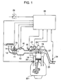
- An engine 10 has a throttle valve 11, a throttle opening degree sensor 12 measuring an opening degree (a throttle opening degree TVO) of the throttle valve 11, an idle speed control valve (an ISC valve) 15 controlling a flow path area of a bypass flow path 14 connected to an air intake pipe 13 while bypassing the throttle valve 11 so as to control an engine speed at an idling time of the engine 10, an air intake pipe pressure sensor 16 detecting a pressure within the air intake pipe 13, and a fuel injection valve 18 injection feeding a fuel demanded by the engine 10 to a combustion chamber 17 in each of cylinders on the basis of a fuel injection signal output by an engine control system 50, in an air intake system.
- the fuel injection valve 18 is provided in each of the cylinders.
- the engine 10 has an air intake valve 26 and an exhaust valve 27 in each of the cylinders.
- the engine 10 is provided with an ignition plug 19 in each of the cylinders for igniting an air-fuel mixture of an air and a fuel fed to the combustion chamber 17, and an ignition coil (an ignition module) 20 feeding an ignition energy on the basis of an ignition signal output by the engine control system 50.
- an ignition plug 19 in each of the cylinders for igniting an air-fuel mixture of an air and a fuel fed to the combustion chamber 17, and an ignition coil (an ignition module) 20 feeding an ignition energy on the basis of an ignition signal output by the engine control system 50.
- the engine 10 is provided with a crank angle sensor (a cam angle sensor) 21 detecting a crank angle, and a water temperature sensor 22 detecting a cooling water temperature.
- a crank angle sensor a cam angle sensor
- a water temperature sensor 22 detecting a cooling water temperature.
- An oxygen concentration sensor 24 measuring an oxygen concentration in an exhaust gas is attached to an exhaust pipe 23 of the engine 10.
- the engine 10 is operated and stopped by an ignition switch 25 corresponding to a main switch.
- the air intake pipe pressure sensor 16 is integrated with an intake gas temperature sensor measuring an intake gas temperature.
- the oxygen concentration sensor 24 is shown as a sensor outputting a proportional signal to an exhaust gas air fuel ratio, however, may be structured such that the exhaust gas output two signals in a rich side and a lean side with respect to a theoretical air fuel ratio.
- a fuel control including an air fuel ratio control of the engine 10, an ignition timing control, an idle control and the like are carried out by the engine control system 50.
- a fuel control is established by detecting an air intake pipe pressure by the air intake pipe pressure sensor 16, however, it goes without saying that the fuel control may be established by detecting the intake air amount of the engine 10.
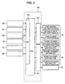
- the engine control system 50 is of an electronic control type by a microcomputer, as shown in Fig. 2 , and has a CPU 51.
- the CPU 51 is provided with an I/O portion 52 converting an electric signal of each of the sensors installed in the engine 10 into a signal for a digital arithmetic processing, and converting the control signal for the digital arithmetic processing into a drive signal of an actual actuator.
- the I/O portion 52 inputs an electric signal from each of the water temperature sensor 22, the crank angle sensor 21, the throttle opening degree sensor 12, the oxygen concentration sensor 24 and the ignition switch 25.
- the CPU 51 outputs an output signal to the fuel injection valve 18 in each of the cylinders, the ignition coil 19 in each of the cylinders, and the ISC valve 15, via an output driver 53.
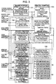
- the engine control system 50 embodies in a software manner each of an engine speed calculating means 101, a basic fuel calculating means 102, a basic fuel correction coefficient calculating means 103, a basic ignition timing calculating means 104, an engine state determining means 105, an ignition timing correcting means 106, a target air fuel ratio setting means 107, an air fuel ratio feedback control coefficient calculating means 108, a fuel characteristic determining means 109, an air intake manifold wall temperature estimating and fuel film correction computing means 110, and a basic fuel correcting means 111, by executing a computer program.
- the engine rotating speed calculating means 101 calculates a rotating speed (an engine speed Ne) per unit time of the engine 10 by counting an electric signal output by the crank angle sensor 21 set at a predetermined crank angle position of the engine 10, mainly an input number per unit time of a pulse signal change, and arithmetically processing.
- the basic fuel calculating means 102 calculates a basic fuel amount demanded by the engine on the basis of the engine speed of the engine 10 computed by the engine speed calculating means 101, and an engine load.
- the engine load is represented by an air intake pipe pressure obtained by converting an output of the air intake pipe pressure sensor 16 installed in the air intake pipe 13 in accordance with a predetermined process, or an engine intake air amount measured by a thermal type air flow meter or the like.
- the basic fuel correction coefficient calculating means 103 calculates a correction coefficient in each of operating ranges of the engine 10 of the basic fuel amount calculated by the basic fuel calculating means 102, on the basis of the engine speed computed by the engine speed calculating means 101 and the engine load mentioned above.
- the basic ignition timing calculating means 104 carried out a calculation of an optimum basic ignition timing in each of the operating ranges of the engine 10 in accordance with a map search, on the basis of the engine speed computed by the engine speed calculating means 101 and the engine load mentioned above.
- the engine state determining means 105 determines a state of the engine 10 intended by a driver, by detecting the opening degree of the throttle valve 11 set in the air intake pipe 13 and adjusting the intake air amount of the engine 10 by the throttle opening degree sensor 12.
- the engine state determined by the engine state determining means 105 is mainly whether or not an idle state is established, and whether or not an acceleration or deceleration state is established.
- the ignition timing correcting means 106 corrects the optimum basic ignition timing searched by the basic ignition timing calculating means 104 in correspondence to the state of the engine 10 determined by the engine state determining means 105.
- the target air fuel ration setting means 107 decides the optimum air fuel ratio in each of the operating ranges of the engine 10 in accordance with the map search or the like, on the basis of the engine speed computed by the engine speed calculating means 101 and the engine load mentioned above.
- the air fuel ratio feedback control coefficient calculating means 108 carried out a feedback control of the fuel on the basis of the output of the oxygen concentration sensor 24 set in the exhaust pipe 23 in such a manner that the air fuel ratio of the air-fuel mixture fed to the engine 10 comes to the target air fuel ratio decided by the target air fuel ratio setting means 107, and calculates the air fuel ratio feedback coefficient.
- the fuel characteristic determining means 109 determines a nature of the fuel on the basis of a fluctuation of the engine speed computed by the engine speed calculating means 101 and the like.
- the determination of the fuel characteristic in this case selectively determines a light fuel, a light-heavy intermediate fuel and a heavy fuel.
- the air intake manifold wall temperature estimating and fuel film correction computing means 110 estimates a fuel film amount of the fuel adhered to the air intake pipe 13, and an air intake manifold wall temperature of the air intake pipe 13 in the portion to which the fuel is adhered, by using the basic fuel amount calculated by the basic fuel calculating means 102, an effective injection fuel amount obtained by applying the correction to the basic fuel amount by the basic fuel correcting means 111, the temperature of the intake air (the intake air temperature) of the engine 10, the engine speed, a water temperature at a time of starting the engine 10, the engine load, and the fuel characteristic determined value of the fuel characteristic determining means 109, and computes the fuel film correction coefficient on the basis of them.
- the basic fuel correcting means 111 applies a correction to the basic fuel calculated by the basic fuel calculating means 102, by the correction coefficient of the basic fuel amount, the engine water temperature, the air fuel ratio feedback coefficient and the fuel film correction coefficient which are mentioned above.
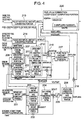
- the air intake manifold wall temperature estimating and fuel film correction computing means 110 has an intake air amount computing portion 201, an intake air amount integrating portion 202, an intake air amount evaporation rate correction computing portion 203, an air intake valve portion rising temperature estimating portion 204, a limiter 205, an inflow fuel combustion contribution rate computing portion 206, an engine water temperature weighted average computing portion 207, a valve temperature weighted average computing portion 208, an air intake manifold wall temperature estimating portion 209, a fuel film amount parameter computing portion 210, a pulse width fuel amount converting portion 214, multipliers 215 and 216, a fuel film amount computing portion 217, a multiplier 218, a pulse width/fuel amount converting portion 219, and a fuel film correction coefficient computing portion 220.
- the intake air amount computing portion 201 calculates an air amount QAR which the engine 10 sucks, on the basis of an air intake pipe pressure PM detected by the air intake pipe pressure sensor 16, and an engine speed Ne computed by the engine speed calculating means 101.
- the intake air amount QAR is calculated on the basis of the engine speed Ne and the air intake pipe pressure PM, however, in the system measuring the intake air amount by the thermal type air flow meter or the like, the intake air amount computing portion 201 is not necessary.
- the intake air amount integrating portion 202 inputs a signal indicating an intake air amount QR from the intake air amount computing portion 201, and calculates an integrated value QASMVT of the intake air amount QAR from the engine start.
- the intake air amount evaporation rate correction computing portion 203 computes a correction coefficient REVPGIN of an evaporation rate of the fuel film on the basis of the intake air amount QAR calculated by the intake air amount computing portion 201.
- the air intake valve portion rising temperature estimating portion 204 estimates and computes a relative rising temperature NLVTM of the air intake valve portion on the basis of the intake air amount integrated value QASMVT obtained by the intake air amount integrating portion 202.
- the rising temperature NLVTM of the air intake valve 26 estimated and computed by the air intake valve portion rising temperature estimating portion 204 is added a start time water temperature TWS by an adder 2041 so as to set a valve temperature VLVTMP.
- the start time water temperature TWS corresponds to a measured value of a cooling water temperature at the engine start time obtained by the water temperature sensor 22.
- valve temperature VLVTMP is applied an upper limit value restriction by the limiter 205, and a fuel contribution rate RWFLBRN of the inflow fuel is calculated by the inflow fuel combustion contribution rate computing portion 206 by using the value.
- the engine water temperature weighted average computing portion 207 applies a weighted average to the engine water temperature (the cooling water temperature) TW detected by the water temperature sensor 22.
- the valve temperature weighted average computing portion 208 applies a weighted average to the valve temperature VLVTMP mentioned above.
- the air intake manifold wall temperature estimating portion 209 is structured such as to estimate a representative temperature of the position to which the injection fuel is adhered, and estimates and calculates an air intake manifold wall temperature (an air intake manifold wall temperature estimated value) TWLLFL by using the intake air temperature TA of the engine 10, the intake air amount QAR, the weighted average value of the engine water temperature TW, the weighted average value of the valve temperature VLVTMP, a fuel film amount WFMOUT mentioned below, an adhered fuel amount ADHTIM mentioned below, and the engine start time water temperature TWS.
- an air intake manifold wall temperature (an air intake manifold wall temperature estimated value) TWLLFL by using the intake air temperature TA of the engine 10, the intake air amount QAR, the weighted average value of the engine water temperature TW, the weighted average value of the valve temperature VLVTMP, a fuel film amount WFMOUT mentioned below, an adhered fuel amount ADHTIM mentioned below, and the engine start time water temperature TWS.
- the fuel film amount parameter computing portion 210 is structured such as to input the fuel characteristic determined value, and the signal indicating the air intake manifold wall temperature WLLFL estimated by the air intake manifold wall temperature estimating portion 209 so as to decide a parameter relating to the fuel film amount, and computes a fuel adhesion rate RADHES at which the injection fuel is adhered to the fuel film by a fuel adhesion rate computing portion 211, an upper limit value MSFLHLM of the fuel film amount by a fuel film amount upper limit value computing portion 212, and a fuel evaporation rate REVAPO per unit time from the fuel film by a unit time evaporation rate computing portion 213, on the basis of the fuel characteristic determined value, and the estimated air intake manifold wall temperature WLLFL.
- a pulse width/fuel amount converting portion 214 converts an effective fuel injection pulse width TIOU correlating with the actually injected injection fuel amount into an effective injection fuel amount MTIOUT.
- a multiplier 215 corresponds to an air intake pipe adhered fuel amount computing means, and calculates an adhered fuel amount ADHTIM to the fuel film by multiplying the effective injection fuel amount MTIOUT converted by the pulse width/fuel amount converting portion 214 by the fuel adhesion rate RADHES computed by the fuel adhesion rate computing portion 211.
- a multiplier 216 corrects the intake air amount of the fuel evaporation rate REVAPO by multiplying the fuel evaporation rate REVAPO computed by the unit time evaporation rate computing portion 213 by the evaporation rate correction coefficient REVPGIN computed by the intake air amount evaporation rate correction computing portion 203.
- a fuel film amount computing portion 217 computes a fuel film amount WFMOUNT and a fuel film amount evaporation amount MASSWFL by using the adhered fuel amount ADHTIM output by the multiplier 215, the fuel film amount upper limit value REVAPO computed by the fuel film amount upper limit value computing portion 212, and the evaporation rate intake air amount correction amount (REVAPO x REVPGIN) output by the multiplier 216.
- the fuel film amount computing portion 217 outputs an inflow component WFFLOW to the cylinder (the combustion chamber 17) of the fuel film, and the previous fuel film amount wfmount in addition to the fuel film amount WFMOUNT, and the fuel film evaporation amount MASSWFL.
- a multiplier 218 multiplies the fuel contribution rate RWFLBRN computed by the inflow fuel combustion contribution rate computing portion 206, and the inflow component WFFLOW of the fuel film to the cylinder computed by the fuel film amount computing portion 217, and calculates the fuel film inflow combustion contribution rate MWFLBRN.
- a pulse width/fuel amount converting portion 219 converts a pulse width TI of the basic fuel output by the basic fuel calculating means 102 into the basic fuel amount MNTTI.
- a fuel film correction coefficient computing portion 220 calculates a fuel film correction coefficient KWFR of the injected fuel by using the basic fuel amount MNTTI, the fuel adhesion rate RADHES, the fuel film amount WFMOUNT, and the fuel film inflow combustion contribution component MWFLBRN.
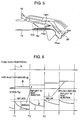
- Fig. 5 shows one example of a behavior of the fuel injected to the air intake passage by the fuel injection valve 18.
- the fuel injected by the fuel injection valve 18 is divided into a fuel Fijw adhered to a fuel film Ffw of the air intake passage and a fuel Fijdin directly flowing into the cylinder.
- the fuel Fin flowing into the cylinder forms a fuel Fijdin structured such that the fuel injected by the fuel injection valve 18 directly flows into the cylinder, an evaporated fuel Ffwv evaporated from the fuel film Ffw, and a fuel Ffwin (WFFLOW) structured such that the fuel film Ffw flows into the cylinder.
- WFFLOW fuel Ffwin
- the expression (1) expresses an increase and decrease of the fuel film between a small section, and expresses that a value obtained by subtracting the fuel film evaporation component (WFMOUNT x REVAPO) from the injection fuel adhesion component (MTIOUT x RADHES) comes to an inclination of the increase and decrease of the fuel film.
- the fuel evaporation rate REVAPO here is applied the correction of the fuel film evaporation rate corresponding to the intake air amount mentioned above.
- the expression (2) is obtained by converting the expression (1) into a difference expression, and an actual computation is carried out on the basis of the expression (2).
- an approximation WFMOUNT ⁇ wfmount is employed in a part thereof.
- the expression (3) corresponds to an upper limit value restriction of the fuel film amount WFMOUNT mentioned above, and the fuel film amount WFMOUNT is restricted by the upper limit of the fuel film amount upper limit value MSFLHLM.
- the expression (4) expresses a computation of the fuel film inflow component WFFLOW to the cylinder at a time of being restricted by the upper limit value.
- the expression (6) corresponds to a calculation of the fuel film evaporation amount MASSWFL, and is executed per fuel injection timing.
- the expression (6) is determined by subtracting the fuel film amount wfmount just after the previous fuel injection from the current fuel film amount WFMOUNT.
- the expression (7) corresponds to a calculation of the fuel film inflow fuel contribution component MWFLBRN, and is determined by multiplying the fuel film inflow component WFFLOW by the fuel film inflow fuel combustion contribution rate RWFLBRN.
- a relation between the fuel film correction basic fuel amount MNTTI and the effective injection fuel amount MTIOUT is expressed by the expression (8), and can be expressed as the fuel film correction value coefficient KWFR by modifying from the expression (8) to the expression (9).
- a relation between the basic fuel amount MNTTI and the effective injection fuel amount MTIOUT comes to the expression (10).
- the effective injection fuel amount MTIOUT may be determined directly from the expression (8) without determining the fuel film correction coefficient KWFR.
- Fig. 6 is one example obtained by expressing the relations (1) to (10) by a time chart.
- Reference symbol A denotes a fuel injection timing, and a fuel injection amount B is going to be changed as shown by the drawing in correspondence to the timing.
- Reference symbol C denotes a behavior of the fuel film, and a difference of the fuel film (the fuel film evaporation amount) MASSWFL between a time point T1 and a time point T2 is reflected to the next injection amount.
- a line D corresponds to a fuel film amount upper limit value MSFLHLM, and in the fuel film inflow component FFLOW getting over the fuel film amount upper limit value MSFLHLM in the fuel film at a time point T3, an amount obtained by multiplying the fuel film inflow component WFFLOW by the fuel film inflow fuel combustion contribution rate RWFLBRN is reflected to the next injection amount.
- Fig. 7 shows one example of a detailed embodiment of the fuel film amount parameter computing portion 210.
- the air intake manifold wall temperature (the air intake manifold wall temperature estimated value) TWLLFL estimated by the air intake manifold wall temperature estimating portion 209 is input to the fuel adhesion rate computing portion 211, the fuel film amount upper limit value computing portion 212 and the unit time evaporation rate computing portion 213 so as to respectively search by table the fuel adhesion rate RADHES, the fuel film amount upper limit value MSFLHLM and the fuel evaporation rate REVAPO.
- the fuel adhesion rate computing portion 211, the fuel film amount upper limit value computing portion 212 and the unit time evaporation rate computing portion 213 are respectively set a plurality of tables, and are switched by switches 706, 707 and 708 in correspondence to the determined value (light/light-heavy intermediate characteristic/heavy) of the fuel characteristic determining means 109 so as to be output.
- Fig. 8 shows a detailed example of the intake air amount computing portion 201 to the inflow fuel combustion contribution rate computing portion 206.
- the intake air amount computing portion 201 computes the intake air amount QAR by multiplying the air intake pipe pressure PM, the engine speed Ne and the constant K.
- the intake air amount computing portion 201 is not necessary, and the intake air amount is directly used.
- the air intake pipe pressure used in the other computing portions employs an engine load Tp obtained by dividing the intake air amount QAR computed by the engine load computing portion 802 by the engine speed Ne.
- the intake air amount evaporation rate correction computing portion 203 determines a correction coefficient REVPGIN of the evaporation rate of the fuel film in accordance with the table search on the basis of the intake air amount QAR.
- the intake air amount integrating portion 202 executes an integration of the intake air amount QAR.
- the air intake valve portion rising temperature estimating portion 204 searches by table a rising temperature VLVTM of the air intake valve 26 on the basis of the integrated value QASMVT of the intake air amount.
- the rising temperature VLVTM of the air intake valve 26 is added the start time water temperature by the adder 2041 so as to come to the valve temperature VLVTMP, and is applied upper and lower limit values by the limiter 205.
- the upper and lower limit values by the limiter 205 is searched by map in the air intake pipe pressure (the engine load) PM and the engine speed Ne by a limit value computing portion 807.
- valve temperature VLVTMP applied the upper and lower limit values is output to the air intake manifold wall temperature estimating portion 209, and input to the inflow fuel combustion contribution rate computing portion 206, and the inflow fuel combustion contribution rate computing portion 206 searches by table the combustion contribution rate RWFLBRN of the inflow fuel.
- the combustion contribution rate RWFLBRN of the inflow fuel is output to the fuel film amount computing portion 217.
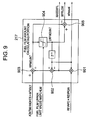
- Fig. 9 shows a detailed example of the fuel film amount computing portion 217.
- the fuel film amount computing portion 217 has a multiplier 901, adders 902 and 903, a true fuel film amount computing portion 904 and an adder 905.
- the multiplier 901 computes a fuel film evaporation amount MASSWFL by multiplying a fuel evaporation rate (REVAPO x REVPGIN) applied the correction of the intake air amount by the previous fuel film amount (the previous value of the true fuel film amount LWFMONT) wfmount.
- a fuel evaporation rate REVAPO x REVPGIN
- the adder 903 adds an adhered fuel amount ADHTIM to an amount (wfmount - MASSWFL) obtained by subtracting the fuel film evaporation amount MASSWFL from the previous fuel film amount wfmount by the adder 902 so as to temporarily set the current fuel film amount WFMOUNT.
- the true fuel film amount computing portion 904 applies the restriction of the upper limit value by the fuel film amount upper limit value MSFLHLM to the fuel film amount WFMOUNT so as to set the true fuel film amount LWFMONT.
- the adder 905 calculates a difference between the temporary fuel film amount WFMOUNT and the true fuel film amount LWFMONT, and calculates the fuel film inflow component WFFLOWE.
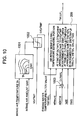
- Fig. 10 shows details of one embodiment of the air intake manifold wall temperature estimating means.
- This embodiment is provided with the air intake manifold wall temperature estimating portion 209, a valve temperature upper limit value computing portion 1001, a limiter 1002, and an adder 1003.
- the valve temperature upper limit value computing portion 1001 searches by map the upper limit value of the valve temperature by the intake air temperature TA and the intake air amount QAR.
- the limiter 1002 applies an upper limit value restriction searched by map by the valve temperature upper limit value computing portion 1001 to the valve temperature VLVTMP.
- the valve temperature LVLVTMP applied the upper limit value restriction is input to the air intake manifold wall temperature estimating portion 209.
- the adder 1003 calculates a difference DLTWFL between the previous fuel film amount wfmount and the adhered fuel amount ADHTIM.
- the calculation of the difference DLTWFL is obtained by subtracting the adhered fuel amount ADHTIM from the previous fuel film amount wfmount.
- the air intake manifold wall temperature estimating portion 209 calculates the air intake manifold wall temperature TWLLFL on the basis of the filter value TWFWFL of the engine water temperature, the valve temperature LVLVTMP applied the upper limit value restriction, the difference DLTWFL between the fuel film amount and the fuel adhesion amount, the previous air intake manifold wall temperature twllfl and the start time water temperature TWS.
- the air intake manifold wall temperature estimating portion 209 calculates the air intake manifold wall temperature TWLLFL in accordance with the following rule so as to output.
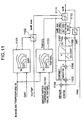
- Fig. 11 shows details of the other embodiment of the air intake manifold wall temperature estimating means.
- This embodiment has a valve temperature upper limit value computing portion 1101, a limiter 1102, a fuel temperature computing portion 1103, multipliers 1104 and 1105, an adder 1106, an air intake manifold wall temperature change amount computing portion 1107, an adder 1108, an initial value setting device 1110 and a limiter 1111.
- the valve temperature upper limit value computing portion 1101 searches by map an upper limit value of the valve temperature VLVTMP on the basis of the intake air temperature TA and the intake air amount QAR.
- the limiter 1102 applies an upper limit value restriction TWLLFLmax searched by map by the valve temperature upper limit value computing portion 1001 to the valve temperature VLVTMP.
- the fuel temperature computing portion 1103 searches by map the fuel temperature TWFUEL on the basis of the intake air temperature TA and the engine water temperature filter value TWFWFL.
- the multiplier 1104 multiplies the previous fuel film amount wfmount and the previous air intake manifold wall temperature twllfl so as to calculate the fuel film heat quantity EWFMNT.
- the multiplier 1105 multiplies the fuel adhered amount ADHTIM and the fuel temperature TWFUEL so as to calculate the adhered fuel heat quantity EADHTIM.
- the adder 1106 calculates a difference (a heat quantity balance) DLTEWF between the fuel film heat quantity EWFMNT and the adhered fuel heat quantity EADHTIM, and the air intake manifold wall temperature change amount computing portion 1107 searches by table the air intake manifold wall temperature change amount DLTTWL in correspondence to the difference DLTEWF.
- the adder 1108 adds the air intake manifold wall temperature change amount DLTTWL and the previous air intake manifold wall temperature twllfl so as to calculate the air intake manifold wall temperature TWLLFL.
- the start time water temperature TWS of the engine 10 is set to the air intake manifold wall temperature TWLLFL by the initial value setting device 1110.
- the other calculated air intake manifold wall temperature TWLLFL is applied the restriction of the upper and lower limit values by the valve temperature TWLLFLmax applied the upper limit value and the valve temperature lower limit value TWLLFLmin corresponding to the fuel temperature TWFUEL, by the limiter 1111 so as to be output.
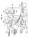
- Fig. 12 shows details of further the other embodiment of the air intake manifold wall temperature estimating means.
- an intake air absorbing heat quantity (an absorbed heat quantity) EQAOUT absorbed from the fuel film is calculated by multiplying the intake air amount QAR and the intake air temperature TA by a multiplier 1201, and thereafter multiplying a specific heat of the air and a coefficient (an intake air heat quantity transmission rate) CEFCAL1 participating in the specific heat of the air and the heat quantity of the fuel film by a multiplier 1204.
- the coefficient CEFCAL1 participating in the heat quantity of the fuel film is searched by table from the intake air amount QAR by a coefficient setting device 1202.
- a coefficient (a valve heat quantity transmission rate) CEFCAL2 in which the heat quantity EVLVTMP of the air intake valve 26 participates in the heat quantity of the fuel film is searched by table on the basis of the intake air amount QAR by a coefficient setting device 1205.
- the heat quantity EVLVTMP of the air intake valve 26 is searched by table from the valve temperature VLVTMP by an air intake valve heat quantity computing portion 1206.
- a multiplier 1207 multiplies the coefficient CEFCAL2 in which the heat quantity EVLVTMP of the air intake valve 26 participates in the heat quantity of the fuel film, and the heat quantity EVLVTMP of the air intake valve 26, and a heat quantity (an applied heat quantity) EVLVIN applied to the fuel film is calculated.
- a fuel temperature computing portion 1208 searches by table the fuel temperature TWFUEL on the basis of the intake air temperature TA and the engine water temperature filter value TWFWEL.
- a multiplier 1209 multiplies the previous air intake manifold wall temperature twllfl and the previous fuel film amount wfmount so as to compute the fuel film heat quantity EWFMNT.
- a multiplier 1210 multiplies the adhered fuel amount ADHTIM and he fuel temperature TWFUEL so as to compute the heat quantity EADHTIM of the adhered fuel.
- An adder 1211 corresponds to a heat quantity balance computing means, adds and subtracts the heat quantity EADHTIM of the adhered fuel, the heat quantity EWFMNT of the fuel film, the intake air amount absorbed heat quantity EQAOUT absorbed from the fuel film, and the heat quantity EVLVIN applied to the fuel film of the valve so as to calculate the heat quantity balance.
- An adder 1212 calculates a total addition amount MFUEL of the previous fuel film amount wfmount and the adhered fuel amount ADHTIM.
- a divider 1213 divides the heat quantity balance computed by the adder 1211 by the total addition amount MFUEL so as to calculate a new air intake manifold wall temperature TWLLFL.
- the start time water temperature TWS is set to the first time wall temperature TWLLFL by an initial value setting device 1214.
- the calculated air intake manifold wall temperature TWLLFL is restricted by the upper and lower limit values by a limiter 1215.
- Figs. 13A to 13E are time charts expressing one example of respective parameter behaviors at a time when the fuel control system corresponding to the subject of the present invention controls the engine 10.
- Fig. 13A shows a behavior of the throttle opening degree THR
- Fig. 13B shows a behavior of the intake air amount QAR
- Fig. 13C shows a behavior of the air intake manifold wall temperature estimated value TWLLFLO
- Fig. 13D shows a behavior of the fuel film amount WFMOUNT
- Fig. 13E shows a behavior of the adhered fuel amount ADHTIM.
- a section E corresponds to a transition section in which the throttle opening degree THR is changed, and a broken line a corresponds to an executed injection fuel pulse width corrected in accordance with the method of the present invention.
- a section F corresponds to an air intake manifold wall temperature falling section, and the adhered fuel amount ADHTIM becomes more than the fuel film amount WFMOUNT as shown by a section H.
- a section G corresponds to an air intake manifold wall temperature rising section, and the fuel film amount WFMOUNT becomes more than the adhered fuel amount ADHTIM as shown by a section I.
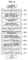
- Fig. 14 shows a control flow of the engine control system 50 of the engine 10 to which the air intake manifold wall temperature estimating apparatus and the fuel control system in accordance with the present invention are applied.
- a step 1401 calculates the engine speed Ne. Further, a step 1402 reads an engine load Tp.
- the engine load Tp is obtained by dividing an air intake pipe negative pressure PM or the intake air amount QAR by the engine speed Ne.
- a step 1403 calculates the basic fuel amount MNTTI.
- a step 1404 searches a correction coefficient of the basis fuel amount MNTTI on the basis of the engine speed Ne and the engine load Tp.
- a step 1405 searches a demanded target air fuel ratio.
- a step 1406 reads an output of the oxygen concentration sensor 24, and a step 1407 carries out an air fuel ratio feedback on the basis of the oxygen concentration sensor output in such a manner that an exhaust gas air fuel ratio comes to the target air fuel ratio, and calculates an air fuel ratio feedback coefficient.
- a step 1408 detects a rotating speed fluctuation on the basis of the engine speed Ne, and determines the fuel characteristic.
- a step 1409 calculates the fuel film correction coefficient KWFR with respect to the basic fuel amount MNTTI.
- a step 1410 applies the air fuel ratio feedback coefficient and the fuel film correction coefficient KWFR to the basic fuel amount MNTTI. Further, a step 1411 sets the injected fuel amount applied the correction to the fuel injecting means.
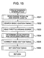
- Fig. 15 shows one example of a detailed flow chart of an ignition timing calculation relation of the engine control system 50.
- a step 1501 reads the engine speed Ne and the engine load Tp.
- a step 1502 searches the basic ignition timing on the basis of the engine speed Ne and the engine load.
- a step 1503 reads the throttle opening degree, and a step 1504 determines the engine state for determining the acceleration or deceleration and the idling.
- a step 1505 calculates the ignition correction amount on the basis of the determined state, and reflects to the basic ignition timing, and a step 1506 sets to the igniting means.
- Figs. 14 and 15 there are shown the example in which the fuel calculation and the ignition timing calculation are calculated at the different interrupting periods, however, the calculating may be carried out at the same timing. Further, the interruption is carried out at the fixed time, however, may be carried out at a timing which is synchronized with the angle of rotation of the engine.
- Fig. 16 shows one example of a detailed flow chart of a computation of the intake air amount to the inflow fuel combustion contribution rate by the air intake manifold wall temperature estimating and fuel film correction computing means 110.
- a step 1601 reads the engine speed Ne and the engine load Tp.
- a step 1602 computes the intake air flow rate QAR.
- the present step is not necessary in the system measuring the intake air amount by the thermal type air flow meter or the like.
- a step 1603 searches the evaporation rate correction coefficient REVPGIN on the basis of the intake air amount QAR.
- a step 1604 integrates the intake air amount after the engine starts (after a complete explosion). In other words, the intake air amount integrated value QASMVT is computed.
- a step 1605 searches the valve rising temperature VLVTM on the basis of the intake air amount integrated value QASMVT.
- a step 1606 reads the start time water temperature TWS, and a step 1607 calculates the valve temperature VLVTMP on the basis of the start time water temperature TWS and the valve rising temperature VLVTM. In this case, an upper limit restriction value is set in the valve temperature.
- a step 1608 searches the inflow fuel combustion contribution rate RWFLBRN on the basis of the valve temperature VLVTMP.
- Fig. 17 shows one example of a detailed flow chart of the air intake manifold wall temperature estimation by the air intake manifold wall temperature estimating portion 209.
- a step 1701 reads the engine water temperature TW, and the valve temperature VLVTMP mentioned above.
- a step 1702 applies a weighted average to each of the engine water temperature TW and the valve temperature VLVTMP.
- a step 1703 reads the intake air temperature TA, the intake air amount QAR, the weighted average value of the engine water temperature, the weighted average value of the valve temperature VLVTMP, the previous fuel film amount wfmont, the fuel adhesion amount ADHTIM, and the engine start time water temperature TWS, and a step 1704 estimates the air intake manifold wall temperature estimated value (the estimated air intake manifold wall temperature) TWLLFL on the basis of them.
- Fig. 18 shows one example of a detailed flow chart of the fuel film amount parameter computation by the fuel film amount parameter computing portion 210.
- a step 1801 reads the air intake manifold wall temperature estimated value TWLLFL mentioned above.
- a step 1802 reads an independently determined fuel characteristic determined value, and a step 1803 selects each of the fuel adhesion rate map, the fuel film amount upper limit value map and the evaporation rate map in correspondence to the fuel characteristic.
- a step 1804 searches the fuel adhesion rate map, the fuel film amount upper limit map and the evaporation rate map selected in correspondence to the fuel characteristic, on the basis of the air intake manifold wall temperature estimated value TWLLFL, and decides respective parameters (the fuel adhesion rate RADHES, the fuel film amount upper limit value MSFLHLM and the fuel evaporation rate REVAPO).
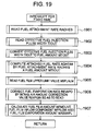
- Fig. 19 shows one example of a detailed flow chart of the fuel film amount computation by the air intake manifold wall temperature estimating and fuel film correction computing means 110.
- a step 1901 reads the fuel adhesion rate RADHES.
- a step 1902 reads the effective fuel injection pulse width TIOUT, and a step 1903 converts the pulse width into the fuel amount MTIOUT.
- a step 1904 multiplies the fuel adhesion rate RADHES and the fuel amount MTIOUT, and computes the adhered fuel amount ADHTIM to the fuel film.
- a step 1905 reads the fuel film amount upper limit value MSFLHLM.
- a step 1906 compensates the fuel evaporation rate REVAPO by the intake air amount correction value REVPGIN.
- a step 1907 computes the fuel film amount WFMOUNT, the fuel film inflow component WFFLOW and the fuel film evaporation amount MASSWFL on the basis of the adhered fuel amount ADHTIM to the fuel film, the fuel film amount upper limit value MSFLHLM, and the fuel evaporation rate REVAPO applied the correction of the intake air amount.
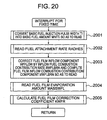
- Fig. 20 shows one example of a detailed flow chart of the fuel film correction coefficient computation by the fuel film correction coefficient computing portion 220.
- a step 2001 converts the basic fuel injection pulse width TI into the basic fuel amount MNTTI.
- a step 2002 reads the fuel adhesion rate RADHES.
- a step 2003 multiplies the fuel film inflow component WFFLOW by the fuel film inflow fuel combustion contribution rate RWFLBRN so as to compute the fuel film inflow combustion contribution component MWFLBRN.
- a step 2004 reads the fuel film evaporation amount MASSWFL.
- a step 2005 calculates the fuel film correction coefficient KWFR on the basis of the expression (9) mentioned above, from the basic fuel amount MNTTI, the fuel adhesion rate RADHES, the fuel film inflow combustion contribution component MWFLBRN and the fuel film evaporation amount MASSWFL.
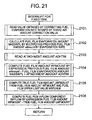
- Fig. 21 shows one example of a detailed flow chart of the fuel film amount computation by the fuel film amount computing member 217 shown in Fig. 9 .
- a step 2101 reads the fuel evaporation rate (REVAPO x REVPGIN) applied the intake air amount correction.
- a step 2102 multiplies the previous fuel film amount wfmount by the corrected fuel evaporation rate (REVAPO x REVPGIN) so as to calculate the fuel film evaporation amount MASSWFL.
- a step 2103 reads the adhesion amount ADHTIM.
- a step 2104 subtracts the fuel film evaporation amount MASSWFL from the previous fuel film amount wfmount, and adds the adhesion amount ADHTIM thereto, and computes the current fuel film amount WFMOUNT.
- a step 2105 computes the true fuel film amount LWFMOUNT by comparing the fuel film amount WFMOUNT with the fuel film amount upper limit value MSFLHLM mentioned above.
- a step 2106 computes the fuel film inflow component WFFLOW by subtracting the true fuel film amount LWFMOUNT from the fuel film amount WFMOUNT.
- Fig. 22 shows one example of a detailed flow chart of the air intake manifold wall temperature estimation by the air intake manifold wall temperature estimating means in accordance with the embodiment shown in Fig. 10 .
- a step 2201 reads the intake air temperature TA, the intake air amount QAR and the valve temperature VLVTMP.
- a step 2202 searches by map the valve temperature upper limit value on the basis of the intake air temperature TA and the intake air amount QAR.
- a step 2203 applies the upper limit value restriction by the valve temperature upper limit value to the read valve temperature VLVTMP, and sets it to the valve temperature LVLVTMP applied the upper limit value restriction.
- a step 2204 reads the engine water temperature filter value TWFWFL.
- a step 2205 determines whether or not the calculation of the estimated air intake manifold wall temperature TWLLFL is the first time. If it is the first time, a step 2206 reads the start time water temperature TWS, and sets the start time water temperature TWS to the initial time estimated air intake manifold wall temperature TWLLFL.
- a step 2207 reads the previous fuel film amount wfmount and the adhesion amount ADHTIM, and calculates the difference DLTWFL of the previous fuel film amount wfmount on the basis of the adhesion amount ADHTIM.
- a step 2208 determines whether or not the difference DLTWFL is equal to or more than the first predetermined value DTMPCHH. If the difference DLTWFL is equal to or more than the first predetermined value DTMPCHH, a step 2209 approximates the estimated air intake manifold wall temperature TWLLFL to the upper limit value restricted valve temperature LVLVTMP at the first predetermined temperature step component DWFLTPH.
- a step 2210 determines whether or not the difference DLTWFL is equal to or more than the second predetermined value DTMPCHL. If the difference DLTWFL is equal to or less than the second predetermined value DTMPCHL, a step 2211 approximates the estimated air intake manifold wall temperature TWLLFL to the engine water temperature filter value TWFWFL at the second predetermined temperature step DWFLTPL component.
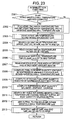
- Fig. 23 shows one example of a detailed flow chart of the air intake manifold wall temperature estimation by the air intake manifold wall temperature estimating means in accordance with the embodiment shown in Fig. 11 .
- a step 2301 determines whether or not the calculation of the estimated air intake manifold wall temperature TWLLFL is the first time. If it is the first time, a step 2302 reads the start time water temperature TWS, and sets it to the first estimated air intake manifold wall temperature TWLLFL.
- a step 2303 reads the intake air temperature TA and the intake air amount QAR. Further, a step 2304 searches by map the valve temperature upper limit value TWLLFLmax on the basis of the intake air temperature TA and the intake air amount QAR.
- a step 2305 reads the engine water temperature filter value TWFWFL.
- a step 2306 searches by map the fuel temperature on the basis of the intake air temperature an the engine water temperature filter value.
- a step 2307 reads the previous fuel film amount wfmount and the adhesion amount ADHTIM.
- a step 2308 computes the fuel film heat quantity EWFMNT by multiplying the previous fuel film amount wfmount and the previous air intake manifold wall temperature twllfl.
- a step 2309 computes the heat quantity EADHTIM of the adhered fuel by multiplying the adhesion amount ADHTIM and the fuel temperature TWFUEL.
- a step 2310 computes the heat quantity balance DLTEWF by subtracting the adhered fuel heat quantity EADHTIM from the fuel film heat quantity EWFMNT.
- a step 2311 searches by table the air intake manifold wall temperature change amount DLTTWL on the basis of the heat quantity balance DLTEWF.
- a step 2312 adds the air intake manifold wall temperature change amount DLTTWL to the previous air intake manifold wall temperature twllfl so as to set to the base value of the current estimated air intake manifold wall temperature TWLLFL.
- a step 2313 applies the upper and lower limit restriction to the base value of the estimated air intake manifold wall temperature TWLLFL by the valve temperature upper limit value TWLLFLmax and the valve temperature lower limit value TWLLFLmin by the fuel temperature TWFUEL so as to set to the final estimated air intake manifold wall temperature TWLLFL.
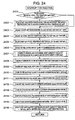
- Fig. 24 shows one example of a detailed flow chart of the air intake manifold wall temperature estimation by the air intake manifold wall temperature estimating means in accordance with the embodiment shown in Fig. 12 .
- a step 2401 determines whether or not the calculation of the estimated air intake manifold wall temperature TWLLFL is the first time. If it is the first time, a step 2402 reads the start time water temperature TWS, and sets it to the first time air intake manifold wall temperature TWLLFL.
- a step 2403 reads the intake air temperature TA and the intake air amount QAR.
- a step 2404 reads the engine water temperature filter value TWFWFL.
- a step 2405 searches by map the fuel temperature TWFUEL on the basis of the intake air temperature TA and the engine water temperature filter value WFWFL.
- a step 2406 searches by table the intake air heat quantity transmission rate CEFCAL1 on the basis of the intake air amount QAR.
- a step 2407 computes the intake air absorbing heat quantity EQAOUT by multiplying the intake air temperature TA, the intake air amount QAR, the intake air heat quantity transmission rate CEFCAL1 and the air specific heat.
- a step 2408 reads the valve temperature VLVTMP, and searches by table the valve heat quantity EVLVTMP on the basis of the valve temperature VLVTMP.
- a step 2409 searches by table the valve heat quantity transmission rate CEFCAL2 on the basis of the intake air amount QAR.
- a step 2410 computes the fed valve heat quantity EVLVIN by multiplying the valve heat quantity EVLVTMP and the valve heat quantity transmission rate CEFCAL2.
- a step 2411 reads the previous fuel film amount wfmount, and the adhered fuel amount ADHTIM.
- a step 2412 computes the fuel film heat quantity EWFMNT by multiplying the previous fuel film amount wfmount and the previous air intake manifold wall temperature twllfl.
- a step 2413 computes the adhered fuel heat quantity EADHTIM by multiplying the adhesion amount ADHTIM and the fuel temperature TWFUEL.
- a step 2414 computes the adhered fuel film amount MFUEL after the fuel is adhered, by adding the previous fuel film amount wfmount and the adhered fuel amount ADHTIM.
- a step 2415 computes the heat quantity balance DLTEWF by adding the adhered fuel heat quantity EADHTIM, the fuel film heat quantity EWFMNT and the fed valve heat quantity EVLIN, and thereafter subtracting the absorbed intake air absorbing heat quantity EQAOUT.
- a step 2416 computes the new estimated air intake manifold wall temperature TWLLFL by dividing the heat quantity balance DLTEWF by the adhered fuel film amount MFEL.
- the estimated air intake manifold wall temperature TWLLFL is applied the upper and lower limit values defined by the constant or the like.
Landscapes
- Engineering & Computer Science (AREA)
- Chemical & Material Sciences (AREA)
- Combustion & Propulsion (AREA)
- Mechanical Engineering (AREA)
- General Engineering & Computer Science (AREA)
- Electrical Control Of Air Or Fuel Supplied To Internal-Combustion Engine (AREA)
Abstract
Description
- The present invention relates to a fuel control system of an internal combustion engine, and more particularly to a fuel control system of an internal combustion engine which can precisely achieve an air-fuel ratio control precision in each of operating ranges of the internal combustion engine, in detail, a demanded air fuel ratio at a time of an engine transition period.
- As a fuel control apparatus of an internal combustion engine, there is a structure which stores a balanced adhering amount of a fuel film with respect to a cooling water temperature of an internal combustion engine (an engine), determines a base fuel film correction amount with respect to a base fuel, further prepares an air intake valve predictive temperature, determines an engine temperature unbalanced state such as a warming up or the like in the case that a difference exists between the cooling water temperature and the air intake valve predictive temperature, calculates a fuel film correction amount of the temperature unbalanced state in correspondence to the temperature difference, and adds to the base fuel film correction amount so as to correct (for example, patent document 1 (
JP-B2-3562026 - The conventional method mentioned above takes into consideration the temperature transition period of the engine such as the warming up or the like, however, does not take into consideration a macroscopic temperature change in a place to which the fuel film is actually adhered. For example, in the conventional method, there is no difference between a cooling water temperature and an air intake valve predictive temperature after the warming up, and the temperature balanced state is determined. Thereafter, the fuel is only corrected on the basis of the change of the balanced fuel film amount in accordance with the region. In other words, the same amount of correction is always applied in the repeat of the transition under the same condition.
- However, the temperature at the position to which the fuel film is adhered is changed before and after the transition, on the basis of a heat quantity of the fuel, a heat transmission from the air intake valve, and a heat quantity absorbed by the intake air amount, the adhesion of the fuel, and an evaporation from the fuel film are differentiated in accordance with the change of the temperature, and the fuel film amount is also changed. In the repeat of the transition under the same condition, in order to achieve the demanded air fuel ratio, it is necessary to carry out the correction in correspondence to the fuel film amount change in accordance with the heat quantity change.
- The present invention is made by taking the problem to be solved into consideration, and an object of the present invention is to provide a fuel control system which can achieve an air fuel ratio control precision in each of operating regions of an engine, particularly precisely achieve a demand air fuel ratio at a time of an engine transition.
- In order to achieve the object mentioned above, in accordance with the present invention, there is provided a fuel control system of an internal combustion engine, comprising:
- a fuel adhesion rate computing means computing a fuel adhesion rate at which an injection fuel is adhered to an air intake pipe on the basis of a representative temperature at a position at which the injection fuel is adhered;
- a fuel evaporation rate computing means computing a fuel evaporation rate of the air intake pipe adhered fuel on the basis of the representative temperature of the position at which the injection fuel is adhered;
- a fuel adhesion amount computing means computing a fuel adhesion amount on the basis of the fuel injection amount and the fuel adhesion rate computed by the fuel adhesion rate computing means;
- a fuel film amount computing means computing a fuel film amount of the air intake pipe on the basis of the fuel adhesion amount computed by the fuel adhesion amount computing means and the fuel evaporation rate computed by the fuel evaporation rate computing means;
- a means for computing an applied heat quantity applied to the fuel adhered to the air intake pipe;
- a means for computing an absorbed heat quantity absorbed from the fuel adhered to the air intake pipe;
- a heat quantity balance computing means computing a balance of the applied heat quantity given to the fuel and the absorbed heat quantity absorbed from the fuel;
- a fuel film estimating means estimating the representative temperature of the position to which the injection fuel is adhered, on the basis of the heat quantity balance computed by the heat quantity balance computing means;
- a fuel film correction coefficient computing means computing a fuel film correction coefficient on the basis of the fuel film amount computed by the fuel film amount computing means; and/or
- a fuel injection amount correcting means correcting the fuel injection amount on the basis of the fuel film correction coefficient computed by the fuel film correction coefficient computing means.
- Further, in order to achieve the object mentioned above, in accordance with the present invention, there is provided a fuel control system of an internal combustion engine, comprising:
- a fuel adhesion rate computing means computing a fuel adhesion rate at which an injection fuel is adhered to an air intake pipe on the basis of a representative temperature at a position at which the injection fuel is adhered;
- a fuel evaporation rate computing means computing a fuel evaporation rate of the air intake pipe adhered fuel on the basis of the representative temperature of the position at which the injection fuel is adhered;
- a fuel adhesion amount computing means computing a fuel adhesion amount on the basis of the fuel injection amount and the fuel adhesion rate computed by the fuel adhesion rate computing means;
- a fuel film amount computing means computing a fuel film amount of the air intake pipe on the basis of the fuel adhesion amount computed by the fuel adhesion amount computing means and the fuel evaporation rate computed by the fuel evaporation rate computing means;
- an engine water temperature detecting means detecting an engine water temperature;
- a valve temperature computing means computing a temperature of the air intake valve;
- a means for comparing an amount of the fuel adhered to the air intake pipe with an amount of the fuel already adhered to the air intake pipe;
- an air intake manifold wall temperature estimating means estimating a representative temperature of the position to which the injection fuel is adhered, on the basis of the engine water temperature, the temperature of the air intake valve and the result of comparison;
- a fuel film correction coefficient computing means computing a fuel film correction coefficient on the basis of the fuel film amount computed by the fuel film amount computing means; and/or
- a fuel injection amount correcting means correcting the fuel injection amount on the basis of the fuel film correction coefficient computed by the fuel film correction coefficient computing means.
- Further, in accordance with the present invention, it is preferable that the balance of the applied heat quantity and the absorbed heat quantity includes a heat quantity near the air intake valve.
- Further, in accordance with the present invention, it is preferable that the heat quantity near the valve is computed by a heat quantity transmission rate of the temperature near the valve determined on the basis of the temperature near the valve and the intake air amount of the internal combustion engine from an integrated value of the intake air amount of the internal combustion engine.
- Further, in accordance with the present invention, it is preferable that the balance of the applied heat quantity and the absorbed heat quantity includes a heat quantity of the intake air amount of the internal combustion engine.
- Further, in accordance with the present invention, it is preferable that the balance of the applied heat quantity and the absorbed heat quantity includes a heat quantity of the fuel.
- Further, in accordance with the present invention, it is preferable that the balance of the applied heat quantity and the absorbed heat quantity includes a heat quantity of an engine cooling water.
- Further, in accordance with the present invention, it is preferable that the air intake manifold wall temperature estimating means has a means for storing a predetermined temperature width with respect to the result of comparison, a means for deciding a reaching temperature to any one of an engine water temperature near the adhered position and the temperature near the air intake valve on the basis of the result of comparison, and a means for approximating to the decided reaching temperature in increments of the predetermined temperature width.
- Further, in accordance with the present invention, it is preferable that the predetermined temperature width with respect to the result of comparison is constituted by a stored parameter group stored in correspondence to a magnitude of the result of comparison.
- In accordance with the fuel control system of the internal combustion engine on the basis of the present invention, the structure is made such as to estimate the temperature (the air intake manifold wall temperature) of the position to which the fuel is adhered by the heat quantity balance applied to the already adhered fuel (the air intake manifold wall temperature), and decide the adhesion rate of the fuel and the evaporation rate from the fuel film from the air intake manifold wall temperature.
- Further, in accordance with the other aspect, since the structure is made such as to determine the fuel temperature estimated value and the valve temperature estimated value in such a manner that the upper and lower limit values can be set, and change the air intake manifold wall temperature on the basis of the quantitative relation between the fuel adhered within the range and the fuel film amount, an over correction is not carried out by an abnormal temperature, and it is possible to keep a robustness.
- It is possible to precisely control on the basis of a target air fuel ratio by estimating the fuel film amount and adding the correction to the fuel injection. Further, it is possible to estimate an accurate air intake manifold wall temperature corresponding to various operation ranges of the internal combustion engine, by taking into consideration the heat quantity of the fuel, the heat quantity of the valve and the heat quantity balance absorbed by the intake air, and it is possible to improve a precision of estimation of the fuel film amount.
- Accordingly, it is possible to determine the correction amount corresponding to the air fuel ratio fluctuation generated by the air intake manifold wall temperature reduction at a time when the fuel injection amount is increased, for example, by a rapid acceleration repeat, and it is possible to improve an air fuel ratio control precision.
- Other objects, features and advantages of the invention will become apparent from the following description of the embodiments of the invention taken in conjunction with the accompanying drawings.
-
-
Fig. 1 is a general schematic view showing one embodiment of an internal combustion engine to which a fuel control apparatus in accordance with the present invention is applied; -
Fig. 2 is a block diagram of an engine control apparatus in accordance with the present embodiment; -
Fig. 3 is a block diagram showing one embodiment of an engine control system serving as a fuel control system provided with an air intake manifold wall temperature estimating apparatus in accordance with the present invention; -
Fig. 4 is a block diagraph showing one specific embodiment of an air intake manifold wall temperature estimating and fuel film correction computing means in the fuel control system in accordance with the present invention; -
Fig. 5 is an explanatory view showing one example of a behavior of a fuel injected to an air intake passage from a fuel injection valve; -
Fig. 6 is a time chart showing a relation among a fuel injection timing, a fuel injection amount and a fuel film amount; -
Fig. 7 is a block diagram showing a detailed embodiment of a fuel film amount parameter computing portion in the fuel control system in accordance with the present invention; -
Fig. 8 is a block diagram showing a detailed example of an intake air amount computing portion to an inflow fuel combustion contribution rate computing portion in accordance with the present embodiment; -
Fig. 9 is a block diagraph showing a detailed example of a fuel film amount computing portion in accordance with the present embodiment; -
Fig. 10 is a block diagram showing a detailed example of an air intake manifold wall temperature estimating means in accordance with the present embodiment; -
Fig. 11 is a block diagram showing detailed of the other embodiment of the air intake manifold wall temperature estimating means; -
Fig. 12 is a block diagram showing details of further the other embodiment of the air intake manifold wall temperature estimating means; -
Figs. 13A to 13E are time charts expressing one example of each of parameter behaviors at a time when the fuel control system corresponding to the subject of the present invention controls the engine; -
Fig. 14 is a flow chart showing a control flow of the engine control system of the engine to which the air intake manifold wall temperature estimating apparatus and the fuel control system in accordance with the present invention are applied; -
Fig. 15 is a detailed flow chart of an ignition timing calculation relation of the engine control system; -
Fig. 16 is a detailed flow chart of an intake air amount to an inflow fuel combustion contribution rate computation by the air intake manifold wall temperature estimating and fuel film correction computing means in accordance with the present embodiment; -
Fig. 17 is a detailed flow chart of an air intake manifold wall temperature estimation by an air intake manifold wall temperature estimating portion in accordance with the present embodiment; -
Fig. 18 is a detailed flow chart of a fuel film amount parameter computation by the fuel film amount parameter computing portion in accordance with the present embodiment; -
Fig. 19 is a detailed flow chart of a fuel film amount computation by the air intake manifold wall temperature estimating and fuel film correction computing means in accordance with the present embodiment; -
Fig. 20 is a detailed flow chart of a fuel film correction coefficient computation by a fuel film correction coefficient computing portion in accordance with the present embodiment; -
Fig. 21 is a detailed flow chart of a fuel film amount computation by a fuel film amount computing member in accordance with the present embodiment; -
Fig. 22 is a detailed flow chart of an air intake manifold wall temperature estimation by the air intake manifold wall temperature estimating means in accordance with the present embodiment; -
Fig. 23 is a detailed flow chart of the air intake manifold wall temperature estimation by an air intake manifold wall temperature estimating means in accordance with the other embodiment; and -
Fig. 24 is a detailed flow chart of the air intake manifold wall temperature estimation by an air intake manifold wall temperature estimating means in accordance with further the other embodiment. - A description will be given in detail of an embodiment of a fuel control system in accordance with the present invention with reference to the accompanying drawings.
- First, a description will be given of one embodiment of an internal combustion engine (an engine) to which the fuel control system in accordance with the present invention is applied, with reference to
Fig. 1 . - An
engine 10 has athrottle valve 11, a throttleopening degree sensor 12 measuring an opening degree (a throttle opening degree TVO) of thethrottle valve 11, an idle speed control valve (an ISC valve) 15 controlling a flow path area of abypass flow path 14 connected to anair intake pipe 13 while bypassing thethrottle valve 11 so as to control an engine speed at an idling time of theengine 10, an air intakepipe pressure sensor 16 detecting a pressure within theair intake pipe 13, and afuel injection valve 18 injection feeding a fuel demanded by theengine 10 to acombustion chamber 17 in each of cylinders on the basis of a fuel injection signal output by anengine control system 50, in an air intake system. Thefuel injection valve 18 is provided in each of the cylinders. Theengine 10 has anair intake valve 26 and anexhaust valve 27 in each of the cylinders. - The
engine 10 is provided with anignition plug 19 in each of the cylinders for igniting an air-fuel mixture of an air and a fuel fed to thecombustion chamber 17, and an ignition coil (an ignition module) 20 feeding an ignition energy on the basis of an ignition signal output by theengine control system 50. - Further, the
engine 10 is provided with a crank angle sensor (a cam angle sensor) 21 detecting a crank angle, and awater temperature sensor 22 detecting a cooling water temperature. - An
oxygen concentration sensor 24 measuring an oxygen concentration in an exhaust gas is attached to anexhaust pipe 23 of theengine 10. - The
engine 10 is operated and stopped by anignition switch 25 corresponding to a main switch. - In this case, the air intake
pipe pressure sensor 16 is integrated with an intake gas temperature sensor measuring an intake gas temperature. - The
oxygen concentration sensor 24 is shown as a sensor outputting a proportional signal to an exhaust gas air fuel ratio, however, may be structured such that the exhaust gas output two signals in a rich side and a lean side with respect to a theoretical air fuel ratio. - A fuel control including an air fuel ratio control of the
engine 10, an ignition timing control, an idle control and the like are carried out by theengine control system 50. In the present embodiment, a fuel control is established by detecting an air intake pipe pressure by the air intakepipe pressure sensor 16, however, it goes without saying that the fuel control may be established by detecting the intake air amount of theengine 10. - The
engine control system 50 is of an electronic control type by a microcomputer, as shown inFig. 2 , and has aCPU 51. TheCPU 51 is provided with an I/O portion 52 converting an electric signal of each of the sensors installed in theengine 10 into a signal for a digital arithmetic processing, and converting the control signal for the digital arithmetic processing into a drive signal of an actual actuator. The I/O portion 52 inputs an electric signal from each of thewater temperature sensor 22, thecrank angle sensor 21, the throttleopening degree sensor 12, theoxygen concentration sensor 24 and theignition switch 25. TheCPU 51 outputs an output signal to thefuel injection valve 18 in each of the cylinders, theignition coil 19 in each of the cylinders, and theISC valve 15, via anoutput driver 53. - Next, a description will be given of one embodiment of the
engine control system 50 serving as a fuel control system provided with an air intake manifold wall temperature estimating apparatus in accordance with the present invention, with reference toFig. 3 . - The
engine control system 50 embodies in a software manner each of an engine speed calculating means 101, a basic fuel calculating means 102, a basic fuel correction coefficient calculating means 103, a basic ignition timing calculating means 104, an engine state determining means 105, an ignition timing correcting means 106, a target air fuel ratio setting means 107, an air fuel ratio feedback control coefficient calculating means 108, a fuel characteristic determining means 109, an air intake manifold wall temperature estimating and fuel film correction computing means 110, and a basic fuel correcting means 111, by executing a computer program. - The engine rotating speed calculating means 101 calculates a rotating speed (an engine speed Ne) per unit time of the
engine 10 by counting an electric signal output by thecrank angle sensor 21 set at a predetermined crank angle position of theengine 10, mainly an input number per unit time of a pulse signal change, and arithmetically processing. - The basic fuel calculating means 102 calculates a basic fuel amount demanded by the engine on the basis of the engine speed of the
engine 10 computed by the engine speed calculating means 101, and an engine load. The engine load is represented by an air intake pipe pressure obtained by converting an output of the air intakepipe pressure sensor 16 installed in theair intake pipe 13 in accordance with a predetermined process, or an engine intake air amount measured by a thermal type air flow meter or the like. - The basic fuel correction coefficient calculating means 103 calculates a correction coefficient in each of operating ranges of the
engine 10 of the basic fuel amount calculated by the basic fuel calculating means 102, on the basis of the engine speed computed by the engine speed calculating means 101 and the engine load mentioned above. - The basic ignition timing calculating means 104 carried out a calculation of an optimum basic ignition timing in each of the operating ranges of the
engine 10 in accordance with a map search, on the basis of the engine speed computed by the engine speed calculating means 101 and the engine load mentioned above. - The engine state determining means 105 determines a state of the
engine 10 intended by a driver, by detecting the opening degree of thethrottle valve 11 set in theair intake pipe 13 and adjusting the intake air amount of theengine 10 by the throttleopening degree sensor 12. The engine state determined by the engine state determining means 105 is mainly whether or not an idle state is established, and whether or not an acceleration or deceleration state is established. - The ignition timing correcting means 106 corrects the optimum basic ignition timing searched by the basic ignition timing calculating means 104 in correspondence to the state of the
engine 10 determined by the enginestate determining means 105. - The target air fuel ration setting means 107 decides the optimum air fuel ratio in each of the operating ranges of the
engine 10 in accordance with the map search or the like, on the basis of the engine speed computed by the engine speed calculating means 101 and the engine load mentioned above. - The air fuel ratio feedback control coefficient calculating means 108 carried out a feedback control of the fuel on the basis of the output of the
oxygen concentration sensor 24 set in theexhaust pipe 23 in such a manner that the air fuel ratio of the air-fuel mixture fed to theengine 10 comes to the target air fuel ratio decided by the target air fuel ratio setting means 107, and calculates the air fuel ratio feedback coefficient. - The fuel characteristic determining means 109 determines a nature of the fuel on the basis of a fluctuation of the engine speed computed by the engine speed calculating means 101 and the like. The determination of the fuel characteristic in this case selectively determines a light fuel, a light-heavy intermediate fuel and a heavy fuel.
- The air intake manifold wall temperature estimating and fuel film correction computing means 110 estimates a fuel film amount of the fuel adhered to the
air intake pipe 13, and an air intake manifold wall temperature of theair intake pipe 13 in the portion to which the fuel is adhered, by using the basic fuel amount calculated by the basic fuel calculating means 102, an effective injection fuel amount obtained by applying the correction to the basic fuel amount by the basic fuel correcting means 111, the temperature of the intake air (the intake air temperature) of theengine 10, the engine speed, a water temperature at a time of starting theengine 10, the engine load, and the fuel characteristic determined value of the fuel characteristic determining means 109, and computes the fuel film correction coefficient on the basis of them. - The basic fuel correcting means 111 applies a correction to the basic fuel calculated by the basic fuel calculating means 102, by the correction coefficient of the basic fuel amount, the engine water temperature, the air fuel ratio feedback coefficient and the fuel film correction coefficient which are mentioned above.
- Next, a description will be given of a specific one embodiment of the air intake manifold wall temperature estimating and fuel film correction computing means 110, with reference to
Fig. 4 . - The air intake manifold wall temperature estimating and fuel film correction computing means 110 has an intake air
amount computing portion 201, an intake airamount integrating portion 202, an intake air amount evaporation ratecorrection computing portion 203, an air intake valve portion risingtemperature estimating portion 204, alimiter 205, an inflow fuel combustion contributionrate computing portion 206, an engine water temperature weightedaverage computing portion 207, a valve temperature weightedaverage computing portion 208, an air intake manifold walltemperature estimating portion 209, a fuel film amountparameter computing portion 210, a pulse width fuelamount converting portion 214,multipliers amount computing portion 217, amultiplier 218, a pulse width/fuelamount converting portion 219, and a fuel film correctioncoefficient computing portion 220. - The intake air
amount computing portion 201 calculates an air amount QAR which theengine 10 sucks, on the basis of an air intake pipe pressure PM detected by the air intakepipe pressure sensor 16, and an engine speed Ne computed by the engine speed calculating means 101. In this case, in the present embodiment, the intake air amount QAR is calculated on the basis of the engine speed Ne and the air intake pipe pressure PM, however, in the system measuring the intake air amount by the thermal type air flow meter or the like, the intake airamount computing portion 201 is not necessary. - The intake air
amount integrating portion 202 inputs a signal indicating an intake air amount QR from the intake airamount computing portion 201, and calculates an integrated value QASMVT of the intake air amount QAR from the engine start. - The intake air amount evaporation rate
correction computing portion 203 computes a correction coefficient REVPGIN of an evaporation rate of the fuel film on the basis of the intake air amount QAR calculated by the intake airamount computing portion 201. - The air intake valve portion rising
temperature estimating portion 204 estimates and computes a relative rising temperature NLVTM of the air intake valve portion on the basis of the intake air amount integrated value QASMVT obtained by the intake airamount integrating portion 202. - The rising temperature NLVTM of the
air intake valve 26 estimated and computed by the air intake valve portion risingtemperature estimating portion 204 is added a start time water temperature TWS by anadder 2041 so as to set a valve temperature VLVTMP. The start time water temperature TWS corresponds to a measured value of a cooling water temperature at the engine start time obtained by thewater temperature sensor 22. - The valve temperature VLVTMP is applied an upper limit value restriction by the
limiter 205, and a fuel contribution rate RWFLBRN of the inflow fuel is calculated by the inflow fuel combustion contributionrate computing portion 206 by using the value. - The engine water temperature weighted
average computing portion 207 applies a weighted average to the engine water temperature (the cooling water temperature) TW detected by thewater temperature sensor 22. - The valve temperature weighted
average computing portion 208 applies a weighted average to the valve temperature VLVTMP mentioned above. - The air intake manifold wall
temperature estimating portion 209 is structured such as to estimate a representative temperature of the position to which the injection fuel is adhered, and estimates and calculates an air intake manifold wall temperature (an air intake manifold wall temperature estimated value) TWLLFL by using the intake air temperature TA of theengine 10, the intake air amount QAR, the weighted average value of the engine water temperature TW, the weighted average value of the valve temperature VLVTMP, a fuel film amount WFMOUT mentioned below, an adhered fuel amount ADHTIM mentioned below, and the engine start time water temperature TWS. - The fuel film amount
parameter computing portion 210 is structured such as to input the fuel characteristic determined value, and the signal indicating the air intake manifold wall temperature WLLFL estimated by the air intake manifold walltemperature estimating portion 209 so as to decide a parameter relating to the fuel film amount, and computes a fuel adhesion rate RADHES at which the injection fuel is adhered to the fuel film by a fuel adhesionrate computing portion 211, an upper limit value MSFLHLM of the fuel film amount by a fuel film amount upper limitvalue computing portion 212, and a fuel evaporation rate REVAPO per unit time from the fuel film by a unit time evaporationrate computing portion 213, on the basis of the fuel characteristic determined value, and the estimated air intake manifold wall temperature WLLFL. - A pulse width/fuel
amount converting portion 214 converts an effective fuel injection pulse width TIOU correlating with the actually injected injection fuel amount into an effective injection fuel amount MTIOUT. - A
multiplier 215 corresponds to an air intake pipe adhered fuel amount computing means, and calculates an adhered fuel amount ADHTIM to the fuel film by multiplying the effective injection fuel amount MTIOUT converted by the pulse width/fuelamount converting portion 214 by the fuel adhesion rate RADHES computed by the fuel adhesionrate computing portion 211. - A
multiplier 216 corrects the intake air amount of the fuel evaporation rate REVAPO by multiplying the fuel evaporation rate REVAPO computed by the unit time evaporationrate computing portion 213 by the evaporation rate correction coefficient REVPGIN computed by the intake air amount evaporation ratecorrection computing portion 203. - A fuel film
amount computing portion 217 computes a fuel film amount WFMOUNT and a fuel film amount evaporation amount MASSWFL by using the adhered fuel amount ADHTIM output by themultiplier 215, the fuel film amount upper limit value REVAPO computed by the fuel film amount upper limitvalue computing portion 212, and the evaporation rate intake air amount correction amount (REVAPO x REVPGIN) output by themultiplier 216. The fuel filmamount computing portion 217 outputs an inflow component WFFLOW to the cylinder (the combustion chamber 17) of the fuel film, and the previous fuel film amount wfmount in addition to the fuel film amount WFMOUNT, and the fuel film evaporation amount MASSWFL. - A
multiplier 218 multiplies the fuel contribution rate RWFLBRN computed by the inflow fuel combustion contributionrate computing portion 206, and the inflow component WFFLOW of the fuel film to the cylinder computed by the fuel filmamount computing portion 217, and calculates the fuel film inflow combustion contribution rate MWFLBRN. - A pulse width/fuel
amount converting portion 219 converts a pulse width TI of the basic fuel output by the basic fuel calculating means 102 into the basic fuel amount MNTTI. - A fuel film correction
coefficient computing portion 220 calculates a fuel film correction coefficient KWFR of the injected fuel by using the basic fuel amount MNTTI, the fuel adhesion rate RADHES, the fuel film amount WFMOUNT, and the fuel film inflow combustion contribution component MWFLBRN. -
Fig. 5 shows one example of a behavior of the fuel injected to the air intake passage by thefuel injection valve 18. The fuel injected by thefuel injection valve 18 is divided into a fuel Fijw adhered to a fuel film Ffw of the air intake passage and a fuel Fijdin directly flowing into the cylinder. The fuel Fin flowing into the cylinder forms a fuel Fijdin structured such that the fuel injected by thefuel injection valve 18 directly flows into the cylinder, an evaporated fuel Ffwv evaporated from the fuel film Ffw, and a fuel Ffwin (WFFLOW) structured such that the fuel film Ffw flows into the cylinder. - Enciphering the behavior of the fuel mentioned above, the following expressions can be obtained.


In this case, - WFMOUNT:
- fuel film amount
- LWFMOUNT:
- true fuel film amount
- wfmount:
- previous fuel film amount
- MTIOUT:
- effective injection fuel amount
- RADHES:
- fuel adhesion rate
- REVAPO:
- fuel evaporation rate
- WFFLOW:
- fuel film inflow component
- MSFLHLM:
- fuel film amount upper limit value
- Δt:
- calculation cycle
- The expression (1) expresses an increase and decrease of the fuel film between a small section, and expresses that a value obtained by subtracting the fuel film evaporation component (WFMOUNT x REVAPO) from the injection fuel adhesion component (MTIOUT x RADHES) comes to an inclination of the increase and decrease of the fuel film. In this case, the fuel evaporation rate REVAPO here is applied the correction of the fuel film evaporation rate corresponding to the intake air amount mentioned above.
- The expression (2) is obtained by converting the expression (1) into a difference expression, and an actual computation is carried out on the basis of the expression (2). In the expression (2), an approximation WFMOUNT ≒ wfmount is employed in a part thereof. The expression (3) corresponds to an upper limit value restriction of the fuel film amount WFMOUNT mentioned above, and the fuel film amount WFMOUNT is restricted by the upper limit of the fuel film amount upper limit value MSFLHLM. The expression (4) expresses a computation of the fuel film inflow component WFFLOW to the cylinder at a time of being restricted by the upper limit value.
- Next, a description will be given of a relational expression for applying the fuel film correction to the basic fuel amount MNTTI.



In this case, - MASSWFL:
- fuel flow evaporation amount
- MWFLBRN:
- fuel flow inflow combustion contribution component
- RWFLBRN:
- fuel flow inflow fuel combustion contribution component
- MTIOUT:
- effective injection fuel amount
- MNTTI:
- basic fuel amount
- KWFR:
- fuel film correction coefficient
- The expression (6) corresponds to a calculation of the fuel film evaporation amount MASSWFL, and is executed per fuel injection timing. The expression (6) is determined by subtracting the fuel film amount wfmount just after the previous fuel injection from the current fuel film amount WFMOUNT.
- The expression (7) corresponds to a calculation of the fuel film inflow fuel contribution component MWFLBRN, and is determined by multiplying the fuel film inflow component WFFLOW by the fuel film inflow fuel combustion contribution rate RWFLBRN.
- A relation between the fuel film correction basic fuel amount MNTTI and the effective injection fuel amount MTIOUT is expressed by the expression (8), and can be expressed as the fuel film correction value coefficient KWFR by modifying from the expression (8) to the expression (9).
- A relation between the basic fuel amount MNTTI and the effective injection fuel amount MTIOUT comes to the expression (10). The effective injection fuel amount MTIOUT may be determined directly from the expression (8) without determining the fuel film correction coefficient KWFR.
-
Fig. 6 is one example obtained by expressing the relations (1) to (10) by a time chart. - Reference symbol A denotes a fuel injection timing, and a fuel injection amount B is going to be changed as shown by the drawing in correspondence to the timing. Reference symbol C denotes a behavior of the fuel film, and a difference of the fuel film (the fuel film evaporation amount) MASSWFL between a time point T1 and a time point T2 is reflected to the next injection amount.
- A line D corresponds to a fuel film amount upper limit value MSFLHLM, and in the fuel film inflow component FFLOW getting over the fuel film amount upper limit value MSFLHLM in the fuel film at a time point T3, an amount obtained by multiplying the fuel film inflow component WFFLOW by the fuel film inflow fuel combustion contribution rate RWFLBRN is reflected to the next injection amount.
-
Fig. 7 shows one example of a detailed embodiment of the fuel film amountparameter computing portion 210. - The air intake manifold wall temperature (the air intake manifold wall temperature estimated value) TWLLFL estimated by the air intake manifold wall
temperature estimating portion 209 is input to the fuel adhesionrate computing portion 211, the fuel film amount upper limitvalue computing portion 212 and the unit time evaporationrate computing portion 213 so as to respectively search by table the fuel adhesion rate RADHES, the fuel film amount upper limit value MSFLHLM and the fuel evaporation rate REVAPO. The fuel adhesionrate computing portion 211, the fuel film amount upper limitvalue computing portion 212 and the unit time evaporationrate computing portion 213 are respectively set a plurality of tables, and are switched byswitches -
Fig. 8 shows a detailed example of the intake airamount computing portion 201 to the inflow fuel combustion contributionrate computing portion 206. - The intake air
amount computing portion 201 computes the intake air amount QAR by multiplying the air intake pipe pressure PM, the engine speed Ne and the constant K. - In this case, in the system weighting the intake air amount of the
engine 10 by the thermal type air flow meter or the like, the intake airamount computing portion 201 is not necessary, and the intake air amount is directly used. In this case, the air intake pipe pressure used in the other computing portions employs an engine load Tp obtained by dividing the intake air amount QAR computed by the engineload computing portion 802 by the engine speed Ne. - The intake air amount evaporation rate
correction computing portion 203 determines a correction coefficient REVPGIN of the evaporation rate of the fuel film in accordance with the table search on the basis of the intake air amount QAR. - The intake air
amount integrating portion 202 executes an integration of the intake air amount QAR. The air intake valve portion risingtemperature estimating portion 204 searches by table a rising temperature VLVTM of theair intake valve 26 on the basis of the integrated value QASMVT of the intake air amount. The rising temperature VLVTM of theair intake valve 26 is added the start time water temperature by theadder 2041 so as to come to the valve temperature VLVTMP, and is applied upper and lower limit values by thelimiter 205. The upper and lower limit values by thelimiter 205 is searched by map in the air intake pipe pressure (the engine load) PM and the engine speed Ne by a limitvalue computing portion 807. The valve temperature VLVTMP applied the upper and lower limit values is output to the air intake manifold walltemperature estimating portion 209, and input to the inflow fuel combustion contributionrate computing portion 206, and the inflow fuel combustion contributionrate computing portion 206 searches by table the combustion contribution rate RWFLBRN of the inflow fuel. The combustion contribution rate RWFLBRN of the inflow fuel is output to the fuel filmamount computing portion 217. -
Fig. 9 shows a detailed example of the fuel filmamount computing portion 217. - The fuel film
amount computing portion 217 has amultiplier 901,adders amount computing portion 904 and anadder 905. - The
multiplier 901 computes a fuel film evaporation amount MASSWFL by multiplying a fuel evaporation rate (REVAPO x REVPGIN) applied the correction of the intake air amount by the previous fuel film amount (the previous value of the true fuel film amount LWFMONT) wfmount. - The
adder 903 adds an adhered fuel amount ADHTIM to an amount (wfmount - MASSWFL) obtained by subtracting the fuel film evaporation amount MASSWFL from the previous fuel film amount wfmount by theadder 902 so as to temporarily set the current fuel film amount WFMOUNT. - The true fuel film
amount computing portion 904 applies the restriction of the upper limit value by the fuel film amount upper limit value MSFLHLM to the fuel film amount WFMOUNT so as to set the true fuel film amount LWFMONT. - The
adder 905 calculates a difference between the temporary fuel film amount WFMOUNT and the true fuel film amount LWFMONT, and calculates the fuel film inflow component WFFLOWE. -
Fig. 10 shows details of one embodiment of the air intake manifold wall temperature estimating means. - This embodiment is provided with the air intake manifold wall
temperature estimating portion 209, a valve temperature upper limitvalue computing portion 1001, alimiter 1002, and anadder 1003. - The valve temperature upper limit
value computing portion 1001 searches by map the upper limit value of the valve temperature by the intake air temperature TA and the intake air amount QAR. Thelimiter 1002 applies an upper limit value restriction searched by map by the valve temperature upper limitvalue computing portion 1001 to the valve temperature VLVTMP. The valve temperature LVLVTMP applied the upper limit value restriction is input to the air intake manifold walltemperature estimating portion 209. - The
adder 1003 calculates a difference DLTWFL between the previous fuel film amount wfmount and the adhered fuel amount ADHTIM. The calculation of the difference DLTWFL is obtained by subtracting the adhered fuel amount ADHTIM from the previous fuel film amount wfmount. - The air intake manifold wall
temperature estimating portion 209 calculates the air intake manifold wall temperature TWLLFL on the basis of the filter value TWFWFL of the engine water temperature, the valve temperature LVLVTMP applied the upper limit value restriction, the difference DLTWFL between the fuel film amount and the fuel adhesion amount, the previous air intake manifold wall temperature twllfl and the start time water temperature TWS. - The air intake manifold wall
temperature estimating portion 209 calculates the air intake manifold wall temperature TWLLFL in accordance with the following rule so as to output. - (1) In the case that the calculation of the air intake manifold wall temperature TWLLFL is the first time, the air intake manifold wall temperature TWLLFL is set to the start time water temperature TWS.
- (2) In the case that the difference DLTWFL between the previous fuel film amount wfmount and the adhered fuel amount ADHTIM is larger than a first predetermined value DTMPCHH, the previous air intake manifold wall temperature twllfl is approximated to the valve temperature LVLVTMP applied the upper limit value restriction in increments of a predetermined value (a first predetermined temperature step component) DWFLTMPH.
- (3) In the case that the difference DLTWFL between the previous fuel film amount wfmount and the adhered fuel amount ADHTIM is equal to or less than a second predetermined value DTMPCHL, the previous air intake manifold wall temperature twllfl is approximated to the engine water temperature filter value TWFWFL in increments of a predetermined value (a second predetermined temperature step component) DWFLTMPL.
-
Fig. 11 shows details of the other embodiment of the air intake manifold wall temperature estimating means. - This embodiment has a valve temperature upper limit
value computing portion 1101, alimiter 1102, a fueltemperature computing portion 1103,multipliers adder 1106, an air intake manifold wall temperature changeamount computing portion 1107, anadder 1108, an initialvalue setting device 1110 and alimiter 1111. - The valve temperature upper limit
value computing portion 1101 searches by map an upper limit value of the valve temperature VLVTMP on the basis of the intake air temperature TA and the intake air amount QAR. Thelimiter 1102 applies an upper limit value restriction TWLLFLmax searched by map by the valve temperature upper limitvalue computing portion 1001 to the valve temperature VLVTMP. - The fuel
temperature computing portion 1103 searches by map the fuel temperature TWFUEL on the basis of the intake air temperature TA and the engine water temperature filter value TWFWFL. - The
multiplier 1104 multiplies the previous fuel film amount wfmount and the previous air intake manifold wall temperature twllfl so as to calculate the fuel film heat quantity EWFMNT. - The
multiplier 1105 multiplies the fuel adhered amount ADHTIM and the fuel temperature TWFUEL so as to calculate the adhered fuel heat quantity EADHTIM. - The
adder 1106 calculates a difference (a heat quantity balance) DLTEWF between the fuel film heat quantity EWFMNT and the adhered fuel heat quantity EADHTIM, and the air intake manifold wall temperature changeamount computing portion 1107 searches by table the air intake manifold wall temperature change amount DLTTWL in correspondence to the difference DLTEWF. - The
adder 1108 adds the air intake manifold wall temperature change amount DLTTWL and the previous air intake manifold wall temperature twllfl so as to calculate the air intake manifold wall temperature TWLLFL. In the case that the calculation of the air intake manifold wall temperature TWLLFL is the first time, the start time water temperature TWS of theengine 10 is set to the air intake manifold wall temperature TWLLFL by the initialvalue setting device 1110. The other calculated air intake manifold wall temperature TWLLFL is applied the restriction of the upper and lower limit values by the valve temperature TWLLFLmax applied the upper limit value and the valve temperature lower limit value TWLLFLmin corresponding to the fuel temperature TWFUEL, by thelimiter 1111 so as to be output. -
Fig. 12 shows details of further the other embodiment of the air intake manifold wall temperature estimating means. - In this embodiment, an intake air absorbing heat quantity (an absorbed heat quantity) EQAOUT absorbed from the fuel film is calculated by multiplying the intake air amount QAR and the intake air temperature TA by a
multiplier 1201, and thereafter multiplying a specific heat of the air and a coefficient (an intake air heat quantity transmission rate) CEFCAL1 participating in the specific heat of the air and the heat quantity of the fuel film by amultiplier 1204. - The coefficient CEFCAL1 participating in the heat quantity of the fuel film is searched by table from the intake air amount QAR by a
coefficient setting device 1202. - Further, a coefficient (a valve heat quantity transmission rate) CEFCAL2 in which the heat quantity EVLVTMP of the
air intake valve 26 participates in the heat quantity of the fuel film is searched by table on the basis of the intake air amount QAR by acoefficient setting device 1205. The heat quantity EVLVTMP of theair intake valve 26 is searched by table from the valve temperature VLVTMP by an air intake valve heatquantity computing portion 1206. - A
multiplier 1207 multiplies the coefficient CEFCAL2 in which the heat quantity EVLVTMP of theair intake valve 26 participates in the heat quantity of the fuel film, and the heat quantity EVLVTMP of theair intake valve 26, and a heat quantity (an applied heat quantity) EVLVIN applied to the fuel film is calculated. - A fuel
temperature computing portion 1208 searches by table the fuel temperature TWFUEL on the basis of the intake air temperature TA and the engine water temperature filter value TWFWEL. - A
multiplier 1209 multiplies the previous air intake manifold wall temperature twllfl and the previous fuel film amount wfmount so as to compute the fuel film heat quantity EWFMNT. - A
multiplier 1210 multiplies the adhered fuel amount ADHTIM and he fuel temperature TWFUEL so as to compute the heat quantity EADHTIM of the adhered fuel. - An
adder 1211 corresponds to a heat quantity balance computing means, adds and subtracts the heat quantity EADHTIM of the adhered fuel, the heat quantity EWFMNT of the fuel film, the intake air amount absorbed heat quantity EQAOUT absorbed from the fuel film, and the heat quantity EVLVIN applied to the fuel film of the valve so as to calculate the heat quantity balance. - An
adder 1212 calculates a total addition amount MFUEL of the previous fuel film amount wfmount and the adhered fuel amount ADHTIM. - A divider 1213 divides the heat quantity balance computed by the
adder 1211 by the total addition amount MFUEL so as to calculate a new air intake manifold wall temperature TWLLFL. In this case, in the case that the calculation of the air intake manifold wall temperature TWLLFL is the first time, the start time water temperature TWS is set to the first time wall temperature TWLLFL by an initialvalue setting device 1214. The calculated air intake manifold wall temperature TWLLFL is restricted by the upper and lower limit values by alimiter 1215. -
Figs. 13A to 13E are time charts expressing one example of respective parameter behaviors at a time when the fuel control system corresponding to the subject of the present invention controls theengine 10. -
Fig. 13A shows a behavior of the throttle opening degree THR,Fig. 13B shows a behavior of the intake air amount QAR,Fig. 13C shows a behavior of the air intake manifold wall temperature estimated value TWLLFLO,Fig. 13D shows a behavior of the fuel film amount WFMOUNT, andFig. 13E shows a behavior of the adhered fuel amount ADHTIM. - A section E corresponds to a transition section in which the throttle opening degree THR is changed, and a broken line a corresponds to an executed injection fuel pulse width corrected in accordance with the method of the present invention.
- A section F corresponds to an air intake manifold wall temperature falling section, and the adhered fuel amount ADHTIM becomes more than the fuel film amount WFMOUNT as shown by a section H.
- A section G corresponds to an air intake manifold wall temperature rising section, and the fuel film amount WFMOUNT becomes more than the adhered fuel amount ADHTIM as shown by a section I.
-
Fig. 14 shows a control flow of theengine control system 50 of theengine 10 to which the air intake manifold wall temperature estimating apparatus and the fuel control system in accordance with the present invention are applied. - First, a
step 1401 calculates the engine speed Ne. Further, astep 1402 reads an engine load Tp. In the present embodiment, the engine load Tp is obtained by dividing an air intake pipe negative pressure PM or the intake air amount QAR by the engine speed Ne. - Next, a
step 1403 calculates the basic fuel amount MNTTI. Astep 1404 searches a correction coefficient of the basis fuel amount MNTTI on the basis of the engine speed Ne and the engine load Tp. Astep 1405 searches a demanded target air fuel ratio. Astep 1406 reads an output of theoxygen concentration sensor 24, and astep 1407 carries out an air fuel ratio feedback on the basis of the oxygen concentration sensor output in such a manner that an exhaust gas air fuel ratio comes to the target air fuel ratio, and calculates an air fuel ratio feedback coefficient. - A
step 1408 detects a rotating speed fluctuation on the basis of the engine speed Ne, and determines the fuel characteristic. Astep 1409 calculates the fuel film correction coefficient KWFR with respect to the basic fuel amount MNTTI. - A step 1410 applies the air fuel ratio feedback coefficient and the fuel film correction coefficient KWFR to the basic fuel amount MNTTI. Further, a
step 1411 sets the injected fuel amount applied the correction to the fuel injecting means. -
Fig. 15 shows one example of a detailed flow chart of an ignition timing calculation relation of theengine control system 50. - First, a
step 1501 reads the engine speed Ne and the engine load Tp. Astep 1502 searches the basic ignition timing on the basis of the engine speed Ne and the engine load. - A
step 1503 reads the throttle opening degree, and astep 1504 determines the engine state for determining the acceleration or deceleration and the idling. - Further, a
step 1505 calculates the ignition correction amount on the basis of the determined state, and reflects to the basic ignition timing, and astep 1506 sets to the igniting means. - In this case, in
Figs. 14 and15 , there are shown the example in which the fuel calculation and the ignition timing calculation are calculated at the different interrupting periods, however, the calculating may be carried out at the same timing. Further, the interruption is carried out at the fixed time, however, may be carried out at a timing which is synchronized with the angle of rotation of the engine. -
Fig. 16 shows one example of a detailed flow chart of a computation of the intake air amount to the inflow fuel combustion contribution rate by the air intake manifold wall temperature estimating and fuel film correction computing means 110. - First, a
step 1601 reads the engine speed Ne and the engine load Tp. Astep 1602 computes the intake air flow rate QAR. In this case, although mentioned above, the present step is not necessary in the system measuring the intake air amount by the thermal type air flow meter or the like. - A
step 1603 searches the evaporation rate correction coefficient REVPGIN on the basis of the intake air amount QAR. Astep 1604 integrates the intake air amount after the engine starts (after a complete explosion). In other words, the intake air amount integrated value QASMVT is computed. - Next, a
step 1605 searches the valve rising temperature VLVTM on the basis of the intake air amount integrated value QASMVT. Astep 1606 reads the start time water temperature TWS, and astep 1607 calculates the valve temperature VLVTMP on the basis of the start time water temperature TWS and the valve rising temperature VLVTM. In this case, an upper limit restriction value is set in the valve temperature. Astep 1608 searches the inflow fuel combustion contribution rate RWFLBRN on the basis of the valve temperature VLVTMP. -
Fig. 17 shows one example of a detailed flow chart of the air intake manifold wall temperature estimation by the air intake manifold walltemperature estimating portion 209. - First, a
step 1701 reads the engine water temperature TW, and the valve temperature VLVTMP mentioned above. Astep 1702 applies a weighted average to each of the engine water temperature TW and the valve temperature VLVTMP. A step 1703 reads the intake air temperature TA, the intake air amount QAR, the weighted average value of the engine water temperature, the weighted average value of the valve temperature VLVTMP, the previous fuel film amount wfmont, the fuel adhesion amount ADHTIM, and the engine start time water temperature TWS, and astep 1704 estimates the air intake manifold wall temperature estimated value (the estimated air intake manifold wall temperature) TWLLFL on the basis of them. -
Fig. 18 shows one example of a detailed flow chart of the fuel film amount parameter computation by the fuel film amountparameter computing portion 210. - First, a
step 1801 reads the air intake manifold wall temperature estimated value TWLLFL mentioned above. Next, astep 1802 reads an independently determined fuel characteristic determined value, and astep 1803 selects each of the fuel adhesion rate map, the fuel film amount upper limit value map and the evaporation rate map in correspondence to the fuel characteristic. - Further, a
step 1804 searches the fuel adhesion rate map, the fuel film amount upper limit map and the evaporation rate map selected in correspondence to the fuel characteristic, on the basis of the air intake manifold wall temperature estimated value TWLLFL, and decides respective parameters (the fuel adhesion rate RADHES, the fuel film amount upper limit value MSFLHLM and the fuel evaporation rate REVAPO). -
Fig. 19 shows one example of a detailed flow chart of the fuel film amount computation by the air intake manifold wall temperature estimating and fuel film correction computing means 110. - First, a
step 1901 reads the fuel adhesion rate RADHES. Astep 1902 reads the effective fuel injection pulse width TIOUT, and astep 1903 converts the pulse width into the fuel amount MTIOUT. Astep 1904 multiplies the fuel adhesion rate RADHES and the fuel amount MTIOUT, and computes the adhered fuel amount ADHTIM to the fuel film. - Next, a
step 1905 reads the fuel film amount upper limit value MSFLHLM. Astep 1906 compensates the fuel evaporation rate REVAPO by the intake air amount correction value REVPGIN. - Further, a
step 1907 computes the fuel film amount WFMOUNT, the fuel film inflow component WFFLOW and the fuel film evaporation amount MASSWFL on the basis of the adhered fuel amount ADHTIM to the fuel film, the fuel film amount upper limit value MSFLHLM, and the fuel evaporation rate REVAPO applied the correction of the intake air amount. -
Fig. 20 shows one example of a detailed flow chart of the fuel film correction coefficient computation by the fuel film correctioncoefficient computing portion 220. - First, a
step 2001 converts the basic fuel injection pulse width TI into the basic fuel amount MNTTI. Astep 2002 reads the fuel adhesion rate RADHES. - Next, a
step 2003 multiplies the fuel film inflow component WFFLOW by the fuel film inflow fuel combustion contribution rate RWFLBRN so as to compute the fuel film inflow combustion contribution component MWFLBRN. Astep 2004 reads the fuel film evaporation amount MASSWFL. - Further, a
step 2005 calculates the fuel film correction coefficient KWFR on the basis of the expression (9) mentioned above, from the basic fuel amount MNTTI, the fuel adhesion rate RADHES, the fuel film inflow combustion contribution component MWFLBRN and the fuel film evaporation amount MASSWFL. -
Fig. 21 shows one example of a detailed flow chart of the fuel film amount computation by the fuel filmamount computing member 217 shown inFig. 9 . - First, a
step 2101 reads the fuel evaporation rate (REVAPO x REVPGIN) applied the intake air amount correction. A step 2102 multiplies the previous fuel film amount wfmount by the corrected fuel evaporation rate (REVAPO x REVPGIN) so as to calculate the fuel film evaporation amount MASSWFL. - Next, a
step 2103 reads the adhesion amount ADHTIM. Astep 2104 subtracts the fuel film evaporation amount MASSWFL from the previous fuel film amount wfmount, and adds the adhesion amount ADHTIM thereto, and computes the current fuel film amount WFMOUNT. - A
step 2105 computes the true fuel film amount LWFMOUNT by comparing the fuel film amount WFMOUNT with the fuel film amount upper limit value MSFLHLM mentioned above. - Further, a
step 2106 computes the fuel film inflow component WFFLOW by subtracting the true fuel film amount LWFMOUNT from the fuel film amount WFMOUNT. -
Fig. 22 shows one example of a detailed flow chart of the air intake manifold wall temperature estimation by the air intake manifold wall temperature estimating means in accordance with the embodiment shown inFig. 10 . - First, a
step 2201 reads the intake air temperature TA, the intake air amount QAR and the valve temperature VLVTMP. Astep 2202 searches by map the valve temperature upper limit value on the basis of the intake air temperature TA and the intake air amount QAR. Astep 2203 applies the upper limit value restriction by the valve temperature upper limit value to the read valve temperature VLVTMP, and sets it to the valve temperature LVLVTMP applied the upper limit value restriction. Further, astep 2204 reads the engine water temperature filter value TWFWFL. - Next, a
step 2205 determines whether or not the calculation of the estimated air intake manifold wall temperature TWLLFL is the first time. If it is the first time, astep 2206 reads the start time water temperature TWS, and sets the start time water temperature TWS to the initial time estimated air intake manifold wall temperature TWLLFL. - A
step 2207 reads the previous fuel film amount wfmount and the adhesion amount ADHTIM, and calculates the difference DLTWFL of the previous fuel film amount wfmount on the basis of the adhesion amount ADHTIM. - A
step 2208 determines whether or not the difference DLTWFL is equal to or more than the first predetermined value DTMPCHH. If the difference DLTWFL is equal to or more than the first predetermined value DTMPCHH, astep 2209 approximates the estimated air intake manifold wall temperature TWLLFL to the upper limit value restricted valve temperature LVLVTMP at the first predetermined temperature step component DWFLTPH. - A
step 2210 determines whether or not the difference DLTWFL is equal to or more than the second predetermined value DTMPCHL. If the difference DLTWFL is equal to or less than the second predetermined value DTMPCHL, astep 2211 approximates the estimated air intake manifold wall temperature TWLLFL to the engine water temperature filter value TWFWFL at the second predetermined temperature step DWFLTPL component. -
Fig. 23 shows one example of a detailed flow chart of the air intake manifold wall temperature estimation by the air intake manifold wall temperature estimating means in accordance with the embodiment shown inFig. 11 . - First, a
step 2301 determines whether or not the calculation of the estimated air intake manifold wall temperature TWLLFL is the first time. If it is the first time, astep 2302 reads the start time water temperature TWS, and sets it to the first estimated air intake manifold wall temperature TWLLFL. - Next, a
step 2303 reads the intake air temperature TA and the intake air amount QAR. Further, astep 2304 searches by map the valve temperature upper limit value TWLLFLmax on the basis of the intake air temperature TA and the intake air amount QAR. - Next, a
step 2305 reads the engine water temperature filter value TWFWFL. Astep 2306 searches by map the fuel temperature on the basis of the intake air temperature an the engine water temperature filter value. - Next, a
step 2307 reads the previous fuel film amount wfmount and the adhesion amount ADHTIM. - Further, a
step 2308 computes the fuel film heat quantity EWFMNT by multiplying the previous fuel film amount wfmount and the previous air intake manifold wall temperature twllfl. Astep 2309 computes the heat quantity EADHTIM of the adhered fuel by multiplying the adhesion amount ADHTIM and the fuel temperature TWFUEL. - Next, a
step 2310 computes the heat quantity balance DLTEWF by subtracting the adhered fuel heat quantity EADHTIM from the fuel film heat quantity EWFMNT. - Further, a
step 2311 searches by table the air intake manifold wall temperature change amount DLTTWL on the basis of the heat quantity balance DLTEWF. - A
step 2312 adds the air intake manifold wall temperature change amount DLTTWL to the previous air intake manifold wall temperature twllfl so as to set to the base value of the current estimated air intake manifold wall temperature TWLLFL. - Further, a
step 2313 applies the upper and lower limit restriction to the base value of the estimated air intake manifold wall temperature TWLLFL by the valve temperature upper limit value TWLLFLmax and the valve temperature lower limit value TWLLFLmin by the fuel temperature TWFUEL so as to set to the final estimated air intake manifold wall temperature TWLLFL. -
Fig. 24 shows one example of a detailed flow chart of the air intake manifold wall temperature estimation by the air intake manifold wall temperature estimating means in accordance with the embodiment shown inFig. 12 . - First, a
step 2401 determines whether or not the calculation of the estimated air intake manifold wall temperature TWLLFL is the first time. If it is the first time, astep 2402 reads the start time water temperature TWS, and sets it to the first time air intake manifold wall temperature TWLLFL. - Next, a
step 2403 reads the intake air temperature TA and the intake air amount QAR. Astep 2404 reads the engine water temperature filter value TWFWFL. Further, astep 2405 searches by map the fuel temperature TWFUEL on the basis of the intake air temperature TA and the engine water temperature filter value WFWFL. - Next, a
step 2406 searches by table the intake air heat quantity transmission rate CEFCAL1 on the basis of the intake air amount QAR. Astep 2407 computes the intake air absorbing heat quantity EQAOUT by multiplying the intake air temperature TA, the intake air amount QAR, the intake air heat quantity transmission rate CEFCAL1 and the air specific heat. - Next, a
step 2408 reads the valve temperature VLVTMP, and searches by table the valve heat quantity EVLVTMP on the basis of the valve temperature VLVTMP. - Next, a
step 2409 searches by table the valve heat quantity transmission rate CEFCAL2 on the basis of the intake air amount QAR. Astep 2410 computes the fed valve heat quantity EVLVIN by multiplying the valve heat quantity EVLVTMP and the valve heat quantity transmission rate CEFCAL2. - Next, a
step 2411 reads the previous fuel film amount wfmount, and the adhered fuel amount ADHTIM. Astep 2412 computes the fuel film heat quantity EWFMNT by multiplying the previous fuel film amount wfmount and the previous air intake manifold wall temperature twllfl. Astep 2413 computes the adhered fuel heat quantity EADHTIM by multiplying the adhesion amount ADHTIM and the fuel temperature TWFUEL. - Next, a
step 2414 computes the adhered fuel film amount MFUEL after the fuel is adhered, by adding the previous fuel film amount wfmount and the adhered fuel amount ADHTIM. - Next, a
step 2415 computes the heat quantity balance DLTEWF by adding the adhered fuel heat quantity EADHTIM, the fuel film heat quantity EWFMNT and the fed valve heat quantity EVLIN, and thereafter subtracting the absorbed intake air absorbing heat quantity EQAOUT. - Further, a
step 2416 computes the new estimated air intake manifold wall temperature TWLLFL by dividing the heat quantity balance DLTEWF by the adhered fuel film amount MFEL. In this case, the estimated air intake manifold wall temperature TWLLFL is applied the upper and lower limit values defined by the constant or the like. - It should be further understood by those skilled in the art that although the foregoing description has been made on embodiments of the invention, the invention is not limited thereto and various changes and modifications may be made without departing from the spirit of the invention and the scope of the appended claims.
Claims (9)
- A fuel control system of an internal combustion engine, characterized in that the fuel control system comprises:a fuel adhesion rate computing means (211) computing a fuel adhesion rate at which an injection fuel is adhered to an air intake pipe (13) on the basis of a representative temperature at a position at which the injection fuel is adhered;a fuel evaporation rate computing means (213) computing a fuel evaporation rate of the air intake pipe adhered fuel on the basis of the representative temperature of the position at which the injection fuel is adhered;a fuel adhesion amount computing means computing a fuel adhesion amount on the basis of the fuel injection amount and the fuel adhesion rate computed by said fuel adhesion rate computing means (211);a fuel film amount computing means (217) computing a fuel film amount of the air intake pipe on the basis of the fuel adhesion amount computed by the fuel adhesion amount computing means and the fuel evaporation rate computed by said fuel evaporation rate computing means (213);a means for computing an applied heat quantity applied to the fuel adhered to the air intake pipe (13);a means for computing an absorbed heat quantity absorbed from the fuel adhered to the air intake pipe;a heat quantity balance computing means computing a balance of the applied heat quantity given to said fuel and the absorbed heat quantity absorbed from said fuel;an air intake manifold wall temperature estimating means (209) estimating the representative temperature of the position to which said injection fuel is adhered, on the basis of the heat quantity balance computed by said heat quantity balance computing means;a fuel film correction coefficient computing means (220) computing a fuel film correction coefficient on the basis of the fuel film amount computed by said fuel film amount computing means; anda fuel injection amount correcting means correcting the fuel injection amount on the basis of the fuel film correction coefficient computed by said fuel film correction coefficient computing means (220).
- A fuel control system of an internal combustion engine according to claim 1, characterized in that the balance of said applied heat quantity and said absorbed heat quantity includes a heat quantity near the air intake valve.
- A fuel control system of an internal combustion engine according to claim 1 or 2,
characterized
in that the heat quantity near said valve is computed by a heat quantity transmission rate of the temperature near said valve determined on the basis of the temperature near the valve and the intake air amount of the internal combustion engine from an integrated value of the intake air amount of the internal combustion engine. - A fuel control system of an internal combustion engine according to at least one of claims 1 to 3, characterized in that the balance of said applied heat quantity and said absorbed heat quantity includes a heat quantity of the intake air amount of the internal combustion engine.
- A fuel control system of an internal combustion engine according to at least one of claims 1 to 4, characterized in that the balance of said applied heat quantity and said absorbed heat quantity includes a heat quantity of the fuel.
- A fuel control system of an internal combustion engine according to at least one of claims 1 to 5, characterized in that the balance of said applied heat quantity and said absorbed heat quantity includes a heat quantity of an engine cooling water.
- A fuel control system of an internal combustion engine, characterized in that the fuel control system comprises:a fuel adhesion rate computing means (211) computing a fuel adhesion rate at which an injection fuel is adhered to an air intake pipe (13)on the basis of a representative temperature at a position at which the injection fuel is adhered;a fuel evaporation rate computing means (213) computing a fuel evaporation rate of the air intake pipe adhered fuel on the basis of the representative temperature of the position at which the injection fuel is adhered;a fuel adhesion amount computing means computing a fuel adhesion amount on the basis of the fuel injection amount and the fuel adhesion rate computed by said fuel adhesion rate computing means (211);a fuel film amount computing means (217) computing a fuel film amount of the air intake pipe on the basis of the fuel adhesion amount computed by the fuel adhesion amount computing means and the fuel evaporation rate computed by said fuel evaporation rate computing means (213);an engine water temperature detecting means (207) detecting an engine water temperature;a valve temperature computing means (208) computing a temperature of the air intake valve;a means for comparing an amount of the fuel adhered to the air intake pipe with an amount of the fuel already adhered to the air intake pipe;an air intake manifold wall temperature estimating means (209) estimating a representative temperature of the position to which said injection fuel is adhered, on the basis of said engine water temperature, the temperature of said air intake valve and said result of comparison;a fuel film correction coefficient computing means (220) computing a fuel film correction coefficient on the basis of the fuel film amount computed by said fuel film amount computing means (217) ; anda fuel injection amount correcting means correcting the fuel injection amount on the basis of the fuel film correction coefficient computed by said fuel film correction coefficient computing means (220).
- A fuel control system of an internal combustion engine according to claim 7, characterized in that the air intake manifold wall temperature estimating means (209) has a means for storing a predetermined temperature width with respect to said result of comparison, a means for deciding a reaching temperature to any one of an engine water temperature near said adhered position and the temperature near said air intake valve on the basis of said result of comparison, and a means for approximating to said decided reaching temperature in increments of said predetermined temperature width.
- A fuel control system of an internal combustion engine according to claim 7 or 8, characterized in that the predetermined temperature width with respect to said result of comparison is constituted by a stored parameter group stored in correspondence to a magnitude of said result of comparison.
Applications Claiming Priority (1)
| Application Number | Priority Date | Filing Date | Title |
|---|---|---|---|
| JP2007114569A JP4418480B2 (en) | 2007-04-24 | 2007-04-24 | Fuel control device for internal combustion engine |
Publications (2)
| Publication Number | Publication Date |
|---|---|
| EP1985833A2 true EP1985833A2 (en) | 2008-10-29 |
| EP1985833A3 EP1985833A3 (en) | 2011-12-28 |
Family
ID=39677393
Family Applications (1)
| Application Number | Title | Priority Date | Filing Date |
|---|---|---|---|
| EP08007937A Withdrawn EP1985833A3 (en) | 2007-04-24 | 2008-04-24 | Fuel injection control system of internal combustion engine |
Country Status (3)
| Country | Link |
|---|---|
| US (1) | US7761220B2 (en) |
| EP (1) | EP1985833A3 (en) |
| JP (1) | JP4418480B2 (en) |
Cited By (9)
| Publication number | Priority date | Publication date | Assignee | Title |
|---|---|---|---|---|
| CN102678353A (en) * | 2011-03-07 | 2012-09-19 | 通用汽车环球科技运作有限责任公司 | Controlling fuel injection based on fuel volatility |
| US8950366B2 (en) | 2013-05-07 | 2015-02-10 | Ford Global Technologies, Llc | Method for reducing valve recession in gaseous fuel engines |
| EP2921680A1 (en) * | 2014-02-25 | 2015-09-23 | Mitsubishi Jidosha Kogyo K.K. | Apparatus for controlling in-cylinder fuel injection and port fuel injection amounts of an internal combustion engine |
| US9453465B2 (en) | 2013-05-07 | 2016-09-27 | Ford Global Technologies, Llc | Direct injection of diluents or secondary fuels in gaseous fuel engines |
| WO2017036682A1 (en) * | 2015-09-03 | 2017-03-09 | Robert Bosch Gmbh | Method for determining the evaporated portion of a fuel quantity applied by way of port fuel injection |
| US9624872B2 (en) | 2013-05-07 | 2017-04-18 | Ford Global Technologies, Llc | Method for reducing valve recession in gaseous fuel engines |
| ITUB20159587A1 (en) * | 2015-12-22 | 2017-06-22 | Magneti Marelli Spa | METHOD FOR THE CONTROL OF FUEL INJECTION IN AN INTERNAL MOTORCYCLE COMBUSTION ENGINE |
| US9777646B2 (en) | 2013-05-07 | 2017-10-03 | Ford Global Technologies, Llc | Direct injection of diluents or secondary fuels in gaseous fuel engines |
| US9909514B2 (en) | 2013-05-07 | 2018-03-06 | Ford Global Technologies, Llc | Direct injection of diluents or secondary fuels in gaseous fuel engines |
Families Citing this family (4)
| Publication number | Priority date | Publication date | Assignee | Title |
|---|---|---|---|---|
| JP2017032492A (en) | 2015-08-05 | 2017-02-09 | トヨタ自動車株式会社 | Control device for internal combustion engine |
| CN112392620A (en) * | 2019-08-13 | 2021-02-23 | 联合汽车电子有限公司 | Oil film compensation correction method and system in engine acceleration process |
| CN111042942B (en) * | 2019-12-11 | 2022-08-05 | 浙江锋锐发动机有限公司 | Transient fuel control method and device for gasoline direct injection engine and vehicle |
| JP7715123B2 (en) * | 2022-11-01 | 2025-07-30 | トヨタ自動車株式会社 | Engine control device |
Citations (1)
| Publication number | Priority date | Publication date | Assignee | Title |
|---|---|---|---|---|
| JP3562026B2 (en) | 1995-05-18 | 2004-09-08 | 日産自動車株式会社 | Engine air-fuel ratio control device |
Family Cites Families (11)
| Publication number | Priority date | Publication date | Assignee | Title |
|---|---|---|---|---|
| JPS63314339A (en) * | 1987-06-17 | 1988-12-22 | Hitachi Ltd | Air fuel ratio control device |
| JPH02227532A (en) * | 1989-02-28 | 1990-09-10 | Fuji Heavy Ind Ltd | Fuel injection control device |
| US5402763A (en) * | 1990-11-27 | 1995-04-04 | Fuji Jukogyo Kabushiki Kaisha | Method of controlling an engine for a flexible fuel vehicle |
| JP2715207B2 (en) * | 1992-01-16 | 1998-02-18 | 株式会社ユニシアジェックス | Electronic control fuel supply device for internal combustion engine |
| US5353768A (en) * | 1993-11-15 | 1994-10-11 | Ford Motor Company | Fuel control system with compensation for intake valve and engine coolant temperature warm-up rates |
| JP3552255B2 (en) * | 1993-12-09 | 2004-08-11 | 三菱自動車工業株式会社 | Fuel injection control device for internal combustion engine |
| DE4444416A1 (en) * | 1994-12-14 | 1996-06-20 | Bosch Gmbh Robert | Method for influencing fuel metering in an internal combustion engine |
| DE69729981T2 (en) * | 1996-05-28 | 2004-12-16 | Honda Giken Kogyo K.K. | Air / fuel ratio control device using a neural network |
| US6466859B1 (en) * | 1998-06-04 | 2002-10-15 | Yamaha Motor Co Ltd | Control system |
| JP4010280B2 (en) * | 2003-05-27 | 2007-11-21 | トヨタ自動車株式会社 | Fuel injection amount control device for internal combustion engine |
| JP4655983B2 (en) * | 2005-06-13 | 2011-03-23 | トヨタ自動車株式会社 | Control device for internal combustion engine |
-
2007
- 2007-04-24 JP JP2007114569A patent/JP4418480B2/en not_active Expired - Fee Related
-
2008
- 2008-04-23 US US12/108,157 patent/US7761220B2/en not_active Expired - Fee Related
- 2008-04-24 EP EP08007937A patent/EP1985833A3/en not_active Withdrawn
Patent Citations (1)
| Publication number | Priority date | Publication date | Assignee | Title |
|---|---|---|---|---|
| JP3562026B2 (en) | 1995-05-18 | 2004-09-08 | 日産自動車株式会社 | Engine air-fuel ratio control device |
Cited By (12)
| Publication number | Priority date | Publication date | Assignee | Title |
|---|---|---|---|---|
| CN102678353A (en) * | 2011-03-07 | 2012-09-19 | 通用汽车环球科技运作有限责任公司 | Controlling fuel injection based on fuel volatility |
| CN102678353B (en) * | 2011-03-07 | 2016-04-27 | 通用汽车环球科技运作有限责任公司 | Control fuel based on fuel volatility to spray |
| US8950366B2 (en) | 2013-05-07 | 2015-02-10 | Ford Global Technologies, Llc | Method for reducing valve recession in gaseous fuel engines |
| US9453465B2 (en) | 2013-05-07 | 2016-09-27 | Ford Global Technologies, Llc | Direct injection of diluents or secondary fuels in gaseous fuel engines |
| US9624872B2 (en) | 2013-05-07 | 2017-04-18 | Ford Global Technologies, Llc | Method for reducing valve recession in gaseous fuel engines |
| US9777646B2 (en) | 2013-05-07 | 2017-10-03 | Ford Global Technologies, Llc | Direct injection of diluents or secondary fuels in gaseous fuel engines |
| US9909514B2 (en) | 2013-05-07 | 2018-03-06 | Ford Global Technologies, Llc | Direct injection of diluents or secondary fuels in gaseous fuel engines |
| EP2921680A1 (en) * | 2014-02-25 | 2015-09-23 | Mitsubishi Jidosha Kogyo K.K. | Apparatus for controlling in-cylinder fuel injection and port fuel injection amounts of an internal combustion engine |
| US10221802B2 (en) | 2014-02-25 | 2019-03-05 | Mitsubishi Jidosha Kogyo Kabushiki Kaisha | Engine controlling apparatus |
| WO2017036682A1 (en) * | 2015-09-03 | 2017-03-09 | Robert Bosch Gmbh | Method for determining the evaporated portion of a fuel quantity applied by way of port fuel injection |
| KR20180048962A (en) * | 2015-09-03 | 2018-05-10 | 로베르트 보쉬 게엠베하 | Method for determining the amount of fuel vaporized by the port fuel injection system |
| ITUB20159587A1 (en) * | 2015-12-22 | 2017-06-22 | Magneti Marelli Spa | METHOD FOR THE CONTROL OF FUEL INJECTION IN AN INTERNAL MOTORCYCLE COMBUSTION ENGINE |
Also Published As
| Publication number | Publication date |
|---|---|
| JP4418480B2 (en) | 2010-02-17 |
| JP2008267350A (en) | 2008-11-06 |
| US20080270006A1 (en) | 2008-10-30 |
| EP1985833A3 (en) | 2011-12-28 |
| US7761220B2 (en) | 2010-07-20 |
Similar Documents
| Publication | Publication Date | Title |
|---|---|---|
| US7761220B2 (en) | Fuel control system of internal combustion engine | |
| EP0643212B1 (en) | Air-fuel ratio feedback control system for internal combustion engine | |
| US6662640B2 (en) | Air amount detector for internal combustion engine | |
| US6497214B2 (en) | Control system for an internal combustion engine | |
| JP2005282419A (en) | Control device for internal combustion engine | |
| EP1296048B1 (en) | Control system for general-purpose engine | |
| JP2009115012A (en) | Air-fuel ratio control device for internal combustion engine | |
| CN101187341B (en) | Air amount computing unit and fuel control unit of internal combustion engine | |
| KR19990062660A (en) | Engine control unit | |
| JPH10184429A (en) | Engine control system | |
| JP5216787B2 (en) | Engine control device | |
| JP2007092723A (en) | Fuel injection amount control device for internal combustion engine | |
| US7761218B2 (en) | Air-fuel ratio control method of engine and air-fuel ratio control apparatus for same | |
| US20090084351A1 (en) | Idle speed control method for controlling the idle speed of an engine with a continuous variable event and lift system and a fuel control system using the method | |
| JP2754568B2 (en) | Fuel injection amount control device for internal combustion engine | |
| JP4246676B2 (en) | Control device for internal combustion engine | |
| WO2004027241A1 (en) | Fuel injection control device | |
| JP2004156449A (en) | Control device for internal combustion engine | |
| JPH0656112B2 (en) | Fuel injection control device for internal combustion engine | |
| JP4923012B2 (en) | Control device for internal combustion engine | |
| JP2745799B2 (en) | Idling speed controller | |
| JPH0828318A (en) | Engine controller | |
| JPH08128348A (en) | Engine controller | |
| JPH0893527A (en) | Electronically controlled fuel injection system | |
| JPH10122057A (en) | Engine EGR control device |
Legal Events
| Date | Code | Title | Description |
|---|---|---|---|
| PUAI | Public reference made under article 153(3) epc to a published international application that has entered the european phase |
Free format text: ORIGINAL CODE: 0009012 |
|
| 17P | Request for examination filed |
Effective date: 20080424 |
|
| AK | Designated contracting states |
Kind code of ref document: A2 Designated state(s): AT BE BG CH CY CZ DE DK EE ES FI FR GB GR HR HU IE IS IT LI LT LU LV MC MT NL NO PL PT RO SE SI SK TR |
|
| AX | Request for extension of the european patent |
Extension state: AL BA MK RS |
|
| PUAL | Search report despatched |
Free format text: ORIGINAL CODE: 0009013 |
|
| AK | Designated contracting states |
Kind code of ref document: A3 Designated state(s): AT BE BG CH CY CZ DE DK EE ES FI FR GB GR HR HU IE IS IT LI LT LU LV MC MT NL NO PL PT RO SE SI SK TR |
|
| AX | Request for extension of the european patent |
Extension state: AL BA MK RS |
|
| RIC1 | Information provided on ipc code assigned before grant |
Ipc: F02D 33/02 20060101ALN20111121BHEP Ipc: F02D 41/04 20060101ALI20111121BHEP Ipc: F02D 41/10 20060101ALI20111121BHEP Ipc: F02D 41/34 20060101AFI20111121BHEP Ipc: F02D 41/14 20060101ALN20111121BHEP |
|
| AKX | Designation fees paid |
Designated state(s): DE FR GB IT |
|
| 17Q | First examination report despatched |
Effective date: 20160524 |
|
| STAA | Information on the status of an ep patent application or granted ep patent |
Free format text: STATUS: EXAMINATION IS IN PROGRESS |
|
| STAA | Information on the status of an ep patent application or granted ep patent |
Free format text: STATUS: THE APPLICATION IS DEEMED TO BE WITHDRAWN |
|
| 18D | Application deemed to be withdrawn |
Effective date: 20190118 |