EP1985789A2 - A window structure with a translucent strip and a method of manufacturing the window - Google Patents
A window structure with a translucent strip and a method of manufacturing the window Download PDFInfo
- Publication number
- EP1985789A2 EP1985789A2 EP08155103A EP08155103A EP1985789A2 EP 1985789 A2 EP1985789 A2 EP 1985789A2 EP 08155103 A EP08155103 A EP 08155103A EP 08155103 A EP08155103 A EP 08155103A EP 1985789 A2 EP1985789 A2 EP 1985789A2
- Authority
- EP
- European Patent Office
- Prior art keywords
- strip
- window
- transparent
- translucent
- window structure
- Prior art date
- Legal status (The legal status is an assumption and is not a legal conclusion. Google has not performed a legal analysis and makes no representation as to the accuracy of the status listed.)
- Withdrawn
Links
- 238000004519 manufacturing process Methods 0.000 title claims abstract description 7
- 239000011521 glass Substances 0.000 claims abstract description 14
- 230000007704 transition Effects 0.000 claims abstract description 14
- 239000012780 transparent material Substances 0.000 claims abstract description 11
- 239000011324 bead Substances 0.000 claims description 38
- 239000000463 material Substances 0.000 claims description 10
- 230000000694 effects Effects 0.000 description 5
- 239000004033 plastic Substances 0.000 description 2
- NIXOWILDQLNWCW-UHFFFAOYSA-N acrylic acid group Chemical group C(C=C)(=O)O NIXOWILDQLNWCW-UHFFFAOYSA-N 0.000 description 1
- 238000010276 construction Methods 0.000 description 1
- 230000001795 light effect Effects 0.000 description 1
- 230000003287 optical effect Effects 0.000 description 1
- 239000002023 wood Substances 0.000 description 1
Images


Classifications
-
- E—FIXED CONSTRUCTIONS
- E06—DOORS, WINDOWS, SHUTTERS, OR ROLLER BLINDS IN GENERAL; LADDERS
- E06B—FIXED OR MOVABLE CLOSURES FOR OPENINGS IN BUILDINGS, VEHICLES, FENCES OR LIKE ENCLOSURES IN GENERAL, e.g. DOORS, WINDOWS, BLINDS, GATES
- E06B3/00—Window sashes, door leaves, or like elements for closing wall or like openings; Layout of fixed or moving closures, e.g. windows in wall or like openings; Features of rigidly-mounted outer frames relating to the mounting of wing frames
- E06B3/30—Coverings, e.g. protecting against weather, for decorative purposes
- E06B3/301—Coverings, e.g. protecting against weather, for decorative purposes consisting of prefabricated profiled members or glass
-
- E—FIXED CONSTRUCTIONS
- E06—DOORS, WINDOWS, SHUTTERS, OR ROLLER BLINDS IN GENERAL; LADDERS
- E06B—FIXED OR MOVABLE CLOSURES FOR OPENINGS IN BUILDINGS, VEHICLES, FENCES OR LIKE ENCLOSURES IN GENERAL, e.g. DOORS, WINDOWS, BLINDS, GATES
- E06B3/00—Window sashes, door leaves, or like elements for closing wall or like openings; Layout of fixed or moving closures, e.g. windows in wall or like openings; Features of rigidly-mounted outer frames relating to the mounting of wing frames
- E06B3/32—Arrangements of wings characterised by the manner of movement; Arrangements of movable wings in openings; Features of wings or frames relating solely to the manner of movement of the wing
- E06B3/325—Wings opening towards the outside
-
- E—FIXED CONSTRUCTIONS
- E06—DOORS, WINDOWS, SHUTTERS, OR ROLLER BLINDS IN GENERAL; LADDERS
- E06B—FIXED OR MOVABLE CLOSURES FOR OPENINGS IN BUILDINGS, VEHICLES, FENCES OR LIKE ENCLOSURES IN GENERAL, e.g. DOORS, WINDOWS, BLINDS, GATES
- E06B3/00—Window sashes, door leaves, or like elements for closing wall or like openings; Layout of fixed or moving closures, e.g. windows in wall or like openings; Features of rigidly-mounted outer frames relating to the mounting of wing frames
- E06B3/54—Fixing of glass panes or like plates
- E06B3/58—Fixing of glass panes or like plates by means of borders, cleats, or the like
- E06B3/5807—Fixing of glass panes or like plates by means of borders, cleats, or the like not adjustable
- E06B3/5821—Fixing of glass panes or like plates by means of borders, cleats, or the like not adjustable hooked on or in the frame member, fixed by clips or otherwise elastically fixed
Definitions
- a glazing bead is needed between the frame and the glass pane in order to obtain a close fitting between the glass pane and the frame.
- This glazing bead is typically an extruded strip or profile of a plastic material.
- the top surface of the glazing bead must be perfectly flush with the surface of the frame in order to obtain a smooth transition from the indoor frame to the view through the window frame. This perfectly flush transition from the frame to the glazing bead must be achieved during manufacturing of the window.
- the glass pane When the window is opening able, the glass pane must be supported by a frame, the sash, to which the hinges are connected.
- the glazing bead is placed on the side of the glass pane facing the window frame.
- the window frame is having a surface which is substantially perpendicular to a major surface of the plate-shaped element. This surface may also have a minor inclination such that the angle between the plate-shaped element and surface of the window frame is between 90 - 120 degrees.
- Figure 3 and 4 shows practical embodiments of the window structure of figure 2 .
- Both the vertical part 5 and the horizontal part 6 of the sash 4 are extruded profiles.
- the top surface 11 of the glazing bead is flush with the surface 7 of the window frame 3. Both surfaces 11 and 7 are slightly inclined in relation to a horizontal plane.
- the level of the top surface 11 is elevated in relation to the surface 7 of the window frame 3. Without application of a translucent or transparent material a shadow zone will be formed in the transition area between the glazing bead 10 and the window frame 3 in both figure 3 and in figure 4 .
Landscapes
- Engineering & Computer Science (AREA)
- Civil Engineering (AREA)
- Structural Engineering (AREA)
- Securing Of Glass Panes Or The Like (AREA)
Abstract
A window structure comprising a plate-shaped element, such as a glass pane, and a window frame, and further provided with a strip placed between said plate shaped element and said window frame. The strip comprises at least one zone of a translucent or transparent material arranged along the visible transition between the window frame and the strip. The invention further concerns a method of manufacturing a window structure.
Description
- The invention relates to a window structure comprising a plate-shaped element, such as a glass pane, and with a window frame, and further provided with a strip placed between said plate shaped element and said window frame.
- It is known to provide a window structure where the intersection between on one hand the major surface of the window frame substantially perpendicular to the glass pane, and on the other hand the glass pane itself, is made to be as smooth as possible and preferably without obstacles.
- However, in some window constructions a glazing bead is needed between the frame and the glass pane in order to obtain a close fitting between the glass pane and the frame. This glazing bead is typically an extruded strip or profile of a plastic material. Ideally, the top surface of the glazing bead must be perfectly flush with the surface of the frame in order to obtain a smooth transition from the indoor frame to the view through the window frame. This perfectly flush transition from the frame to the glazing bead must be achieved during manufacturing of the window.
- The tolerance during manufacturing of the window, however, means that it is not always possible to achieve this perfectly flush transition. The problem is that even a very small deviation will form a minor elevation difference between the window frame and the glazing bead. This elevation difference will result in a shadow effect making even a very small elevation difference very visible, especially on light-coloured or shiny surfaces. Even if this transition between the window frame and the glazing bead is perfectly flush, any minor groove formed in the transition zone may result in the same shadow effect.
- When the window is opening able, the glass pane must be supported by a frame, the sash, to which the hinges are connected. The glazing bead is placed on the side of the glass pane facing the window frame.
- The movement of the window in the hinges when it is being opened and closed may increase the tolerance on the transition between the window frame and the glazing bead further, and therefore increase the elevation difference.
- The object of the invention has therefore been to find a window structure without any clearly visible obstacles between the window frame and the glass pane.
- This object has been achieved by a window structure where the glazing bead or a strip comprises at least one zone of a translucent or transparent material arranged along the visible transition between the window frame and the strip.
- The application of a translucent or a transparent material has the advantage that light may pass through the material and thereby avoid that any shadow is formed behind the material, or at least the shadowing effect will be reduced in dependency of the fraction of the incoming light which is transmitted through the material. By reducing this shadowing effect the visibility of the transition between the window frame and the strip is reduced.
- Preferably the window frame is having a surface which is substantially perpendicular to a major surface of the plate-shaped element. This surface may also have a minor inclination such that the angle between the plate-shaped element and surface of the window frame is between 90 - 120 degrees.
- In a preferred embodiment of the invention the plate-shaped element of the window structure is supported by a sash. Preferably, the plate-shaped element with this sash will be connected with at least one hinge, such that it is possible to open and close the window. The at least one hinge will typically engage with the window frame such that the plate-shaped element is openable in relation to the window frame.
- In a further embodiment of the invention the strip placed between the plate-shaped element and the window frame is translucent or transparent. This strip may be the glazing bead, a part of the glazing bead or any further strip arranged next to the glazing bead. In different embodiments of the invention the whole strip is either translucent or transparent, and in other embodiments the top part of said strip is either translucent or transparent. By the top part of the strip is meant the accessible part or the visible part in normal use of the window. Obviously, the strip may follow the edge of the plate-shaped element along the whole circumference of the plate-shaped element, or alternatively only a part of the circumference, e.g. 1, 2 or 3 sides of the rectangular window frame.
- In a further embodiment of the invention separate light is emitted through said translucent or transparent material. This is light supplied from a different source than the background day-light. This light could be transmitted through optical fibres or it could originate from a light source placed behind or within the translucent or transparent material, such that light from this light source will be emitted through the material. This will offer the possibility of further light effects in the window structure. For this purpose, as well as others, it could be an advantage with a material partly translucent and partly transparent. The transparent part would preferably be the lower part.
- In an embodiment of the invention the strip has been extruded and a translucent or transparent material has been co-extruded in the surface region of the strip. In general, the translucent or transparent material applied in the invention is preferably a plastic based material, e.g. acrylic.
- In another embodiment of the invention the transparent strip is a separate part connected to the glazing bead or the inner side of the frame, and preferably the transparent strip is covering the space between the gap and the window pane completely. The strip might also in one possible embodiment be integrated with a seal element arranged between the glazing bead and the window pane.
- The invention also covers a method of manufacturing a window structure comprising the steps of a) arranging a window frame; 2) arranging a plate-shaped element, such as a glass pane; 3) arranging a strip between the window frame and the plate-shaped element; wherein the strip or at least a part of the strip is translucent or transparent.
- The invention will be described in further detail with reference to the figures.
-
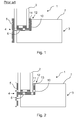
Figure 1 illustrates a schematic window structure according to the prior art. -
Figure 2 illustrates a schematic window structure according to the invention where part of the strip is replaced by a translucent or transparent material. -
Figure 3-7 illustrate specific embodiments of the window structure according to the invention. -
Figure 1 shows aknown window structure 1, with a plate-shaped element 2, e.g. one or more glass layers (two glass layers are shown) and awindow frame 3, often made from wood. Preferably the plate-shaped element 2 is provided with a frame, asash 4, comprising avertical part 5 and ahorizontal part 6. Typically, aglazing bead 10 is attached to thehorizontal part 6 of thesash 4. When manufacturing thewindow structure 1 it was previously common to let theglazing bead 10 project approximately 4 mm above the window frame. When such an elevation difference is to be eliminated, effort will be made to obtain a flush level between asurface 7 of thewindow frame 3 and theaccessible surface 11 of the glazing bead or the strip. However, a typical tolerance on the level of theaccessible surface 11 of theglazing bead 10 is plus/minus 2 mm. - Any minor deviation from such a flush transition between the
window frame 3 and the strip orglazing bead 10, will result in a shadow effect in thearea 12 behind thestrip 10. This shadow, as well as any elevation difference between theframe 3 and thestrip 10, is unwanted for aesthetic reasons. Therefore, a tolerance of plus/minus 2 mm is unacceptably large. However, even a minor tolerance of less than 1 mm may result in an unacceptable shadow. -
Figure 2 shows awindow structure 1 according to the invention, where thestrip 10 only reaches a level below the level of thesurface 7 of thewindow frame 3. Furthermore a translucent ortransparent strip 13 is provided between the plate-shaped element 2 and thewindow frame 3. This translucent ortransparent strip 13 is preferably placed up against the strip, or as part of thestrip 10 and will extend to a level preferably slightly above or flush with thesurface 7 of the window frame. Thestrip 10 may form the glazing bead. The glazing bead may also be formed from a combination of thestrip 10 and the translucent ortransparent strip 13. Finally, the glazing bead may be formed by the translucent ortransparent strip 13 alone. - This means that the whole glazing bead could be translucent or transparent and extend to the level illustrated in
figure 1 above the level of thesurface 7 of the window frame. Another alternative could be that only the part of the strip adjacent thetop surface 7 of the window frame is translucent or transparent. -
Figure 3 and 4 shows practical embodiments of the window structure offigure 2 . Both thevertical part 5 and thehorizontal part 6 of thesash 4 are extruded profiles. This is also the case for thestrip 10, which in the embodiments offigure 3 and 4 forms the glazing bead, where the translucent ortransparent strip 13 forms part of the glazing bead. Infigure 3 thetop surface 11 of the glazing bead is flush with thesurface 7 of thewindow frame 3. Bothsurfaces figure 4 the level of thetop surface 11 is elevated in relation to thesurface 7 of thewindow frame 3. Without application of a translucent or transparent material a shadow zone will be formed in the transition area between theglazing bead 10 and thewindow frame 3 in bothfigure 3 and infigure 4 . - In both
figure 3 and figure 4 the upper part (in relation to the figures) of the glazing bead profile is the part which could be made translucent or transparent when implementing the invention. However, it could also be thewhole glazing bead 10 or a separate strip placed on top of the glazing bead which could be made translucent or transparent. -
Figure 5 and 6 shows further embodiments of the window structure according to the invention. In both figures the translucent ortransparent strip 13 has been arranged separately connected to theglazing bead 10. Thetransparent strip 13 does not need to be arranged connected to theglazing bead 10 as shown infigure 3 - 6 . Thetransparent strip 13 may also be arranged connected to the inner side of thewindow frame 3. Thewindow frame 3 is often L shaped or U-shaped. - Further, a
transparent strip 13 could be arranged on both sides of a gap between thewindow frame 3 and the window sash when the window can be opened. In this embodiment the transition between thetransparent strip 13 and thewindow frame 3 is even more hidden and discreet since the transition occurs between two light transmitting materials. - The embodiment shown in
figure 7 , shows one more embodiment whereby a transparent or translucent strip could be attached to the window structure. In most window structures, arubber seal 20 is arranged pressed in between the window pane and the glazing bead. In the current embodiment, the seal is made from a transparent or translucent material and astrip 13 which covers the top surface of the glazing bead is integrally formed with the seal. In this way, the strip and the seal are applied in the same operation. The strip is furthermore held in place via the seal so additional fastening means between the strip and the glazing bead are not required. - It should be noted that in the current specification, the strip has been added to one type of standard window assembly, however, the person skilled in the art will recognize that the teaching of the current invention could be applied to many other forms of window structure.
Claims (12)
- A window structure (1) comprising a plate-shaped element (2), such as a glass pane, and a window frame (3), and further provided with a strip (10) placed between said plate shaped element (2) and said window frame (3);
characterized in that
said strip (10) comprises at least one zone of a translucent or transparent material (13) arranged along the visible transition between the window frame (3) and the strip (10). - A window structure according to claim 1, wherein said window frame (3) comprises a surface (7) which is substantially perpendicular to a major surface of the plate-shaped element (2).
- A window structure according to claim 1 or 2, wherein the plate-shaped element is supported by a sash (4).
- A window structure according to claim 3, wherein the plate-shaped element with said sash (4) is connected with at least one hinge, such that it is openable.
- A window structure according to any one of the previous claims, wherein said strip (10) is translucent or transparent.
- A window structure according to any one of the previous claims, wherein the accessible part (11) of said strip (10) is translucent or transparent.
- A window structure according to any one of the previous claims, wherein said strip (10) is the glazing bead.
- A window structure according to any one of the previous claims, wherein a light source is arranged such that light from said light source can be emitted through the material (13).
- A window structure according to any one of the previous claims, wherein the strip (10) has been extruded and a translucent or transparent material has been co-extruded in the surface region (11).
- A window structure according to any one of the previous claims, wherein the transparent strip (13) is a separate part connected to the glazing bead or the inner side of the frame (3).
- A window structure according to any one of claims 1-10, wherein the transparent strip (13) is integrally formed with a seal (20) which is arranged between the glazing bead (10) and the plate shaped element (2).
- A method of manufacturing a window structure comprising the steps,- arranging a window frame (3);- arranging a plate-shaped element (2), such as a glass pane;- arranging a strip (10) between the window frame (3) and the plate-shaped element (2);characterized in that at least a part (13) of the strip (10) is translucent or transparent.
Applications Claiming Priority (1)
| Application Number | Priority Date | Filing Date | Title |
|---|---|---|---|
| DKPA200700606 | 2007-04-25 |
Publications (1)
| Publication Number | Publication Date |
|---|---|
| EP1985789A2 true EP1985789A2 (en) | 2008-10-29 |
Family
ID=39758824
Family Applications (1)
| Application Number | Title | Priority Date | Filing Date |
|---|---|---|---|
| EP08155103A Withdrawn EP1985789A2 (en) | 2007-04-25 | 2008-04-24 | A window structure with a translucent strip and a method of manufacturing the window |
Country Status (1)
| Country | Link |
|---|---|
| EP (1) | EP1985789A2 (en) |
Cited By (1)
| Publication number | Priority date | Publication date | Assignee | Title |
|---|---|---|---|---|
| WO2011012295A3 (en) * | 2009-07-28 | 2011-03-31 | Vipo Vinduer A/S | Outwardly opening window |
-
2008
- 2008-04-24 EP EP08155103A patent/EP1985789A2/en not_active Withdrawn
Cited By (1)
| Publication number | Priority date | Publication date | Assignee | Title |
|---|---|---|---|---|
| WO2011012295A3 (en) * | 2009-07-28 | 2011-03-31 | Vipo Vinduer A/S | Outwardly opening window |
Similar Documents
| Publication | Publication Date | Title |
|---|---|---|
| US9016010B2 (en) | Pane module for use in a window | |
| EP3396100A1 (en) | Flat roof window with external screen | |
| US10597930B2 (en) | Impact rated light frame for sectional doors | |
| US7716875B2 (en) | Windows | |
| DE59905402D1 (en) | Method of assembling window or door sashes | |
| EP3228795A1 (en) | Wooden window or door assembly with an external covering | |
| KR20170000381U (en) | Hybrid window and door with synthetic resins and metal | |
| KR102224270B1 (en) | Window having glass guardrail | |
| US4877076A (en) | Screen unit with built-in blind | |
| US20040111972A1 (en) | Sill-free door with lowerable seal | |
| GB2139686A (en) | Secondary glazing frame | |
| GB2282402A (en) | Window assembly | |
| EP3737819B1 (en) | Openable glass structure with protection profiles | |
| KR102086254B1 (en) | Ventilation window for System window | |
| KR20140117101A (en) | Window having a slim frame | |
| AU2020257058A1 (en) | Configurable astragal and snap feature for fenestration systems | |
| GB2147646A (en) | Extruded plastics frame elements with integral seal | |
| CN205689091U (en) | A kind of dust-proof ornamental strip of assembled | |
| KR102086253B1 (en) | System window having ventilation window | |
| GB2235007A (en) | Windows in portable buildings | |
| EP3953554B1 (en) | Sliding window arrangement and use thereof for glazing of a balcony unit | |
| CN200992905Y (en) | Full frameless sliding window | |
| WO2004027193A1 (en) | Window or door structure | |
| GB2177442A (en) | Extruded plastics frame elements | |
| EP3740640B1 (en) | Frameless casement with u-shaped profile |
Legal Events
| Date | Code | Title | Description |
|---|---|---|---|
| PUAI | Public reference made under article 153(3) epc to a published international application that has entered the european phase |
Free format text: ORIGINAL CODE: 0009012 |
|
| AK | Designated contracting states |
Kind code of ref document: A2 Designated state(s): AT BE BG CH CY CZ DE DK EE ES FI FR GB GR HR HU IE IS IT LI LT LU LV MC MT NL NO PL PT RO SE SI SK TR |
|
| AX | Request for extension of the european patent |
Extension state: AL BA MK RS |
|
| STAA | Information on the status of an ep patent application or granted ep patent |
Free format text: STATUS: THE APPLICATION IS DEEMED TO BE WITHDRAWN |
|
| 18D | Application deemed to be withdrawn |
Effective date: 20121101 |