EP1985482A2 - Air outlet - Google Patents
Air outlet Download PDFInfo
- Publication number
- EP1985482A2 EP1985482A2 EP08004744A EP08004744A EP1985482A2 EP 1985482 A2 EP1985482 A2 EP 1985482A2 EP 08004744 A EP08004744 A EP 08004744A EP 08004744 A EP08004744 A EP 08004744A EP 1985482 A2 EP1985482 A2 EP 1985482A2
- Authority
- EP
- European Patent Office
- Prior art keywords
- air
- comfort nozzle
- flaps
- nozzle according
- comfort
- Prior art date
- Legal status (The legal status is an assumption and is not a legal conclusion. Google has not performed a legal analysis and makes no representation as to the accuracy of the status listed.)
- Granted
Links
Images


Classifications
-
- B—PERFORMING OPERATIONS; TRANSPORTING
- B60—VEHICLES IN GENERAL
- B60H—ARRANGEMENTS OF HEATING, COOLING, VENTILATING OR OTHER AIR-TREATING DEVICES SPECIALLY ADAPTED FOR PASSENGER OR GOODS SPACES OF VEHICLES
- B60H1/00—Heating, cooling or ventilating devices
- B60H1/34—Nozzles; Air-diffusers
- B60H1/3414—Nozzles; Air-diffusers with means for adjusting the air stream direction
-
- B—PERFORMING OPERATIONS; TRANSPORTING
- B60—VEHICLES IN GENERAL
- B60H—ARRANGEMENTS OF HEATING, COOLING, VENTILATING OR OTHER AIR-TREATING DEVICES SPECIALLY ADAPTED FOR PASSENGER OR GOODS SPACES OF VEHICLES
- B60H1/00—Heating, cooling or ventilating devices
- B60H1/34—Nozzles; Air-diffusers
- B60H1/3457—Outlets providing a vortex, i.e. a spirally wound air flow
-
- B—PERFORMING OPERATIONS; TRANSPORTING
- B60—VEHICLES IN GENERAL
- B60H—ARRANGEMENTS OF HEATING, COOLING, VENTILATING OR OTHER AIR-TREATING DEVICES SPECIALLY ADAPTED FOR PASSENGER OR GOODS SPACES OF VEHICLES
- B60H1/00—Heating, cooling or ventilating devices
- B60H1/34—Nozzles; Air-diffusers
- B60H2001/3471—Details of actuators
- B60H2001/3478—Details of actuators acting on additional damper doors
Definitions
- the invention relates to a comfort nozzle according to the preamble of claim 1.
- an air vent with an air-supplying air duct and an air guiding device wherein the air duct is divided in the spoiler device into at least two substantially cylindrical sub-ducts and the cylindrical sub-ducts are arranged parallel to each other. Further sub-channels are provided, which generate a swirl flow. Flaps to control the airflow passing through the air vent and to regulate the distribution of the airflow to the two regions of the air vent, which provide a diffused or directional air outlet, are positioned prior to entry into the air vent. In the region of the outlet opening from the air vent slats are arranged in the form of a louver grid to adjust the Heilausströmraum.
- a comfort nozzle which has at least one air guiding device which divides the air duct into a plurality of partial air ducts, a partial air duct for a spot jet and at least one other partial air duct for a diffuse air outlet being formed from the comfort nozzle, and a dosing device by means of which the air distribution the individual partial air channels takes place, wherein the metering device has three flaps with parallel pivot axes, and the outer flaps are single-leaf flaps.
- Such a comfort nozzle can have a simple kinematics for the individual nozzle positions, namely spot beam, diffuse jet and intermediate positions, as well as a shut-off function thereof, as well as a shut-off function.
- the settings mentioned can be realized by adjusting the corresponding flaps.
- the provision of the usual two cams for the control of the spot beam can be omitted, especially if the individual flaps belonging waves are coupled together via tooth segments, and at least one toothed segment is provided with a freewheeling surface.
- the middle flap is particularly preferably a two-leaf flap with a central pivot axis.
- the outer flaps preferably have flap surfaces pointing counter to the air inflow direction, which can be swiveled through an angle of preferably less than 180 °, in particular less than 120 °, and very particularly preferably of approximately 90 ° +/- 20 °.
- the outer flaps are preferably disposed adjacent one another in an end position with their ends spaced from the pivot axes, i. the flap surfaces are arranged in a V-shape. This improves the air distribution and ensures relatively low flow resistance through the flaps.
- the two outer flaps of the metering device are arranged with their pivot axes at the air inlet end of a respective partition.
- the dividing wall preferably already forms an inflow region for the subsequently arranged air-guiding device.
- the middle flap is preferably pivotable through an angle of less than 90 °, in particular preferably at an angle of less than 60 °.
- the swivel angle is preferably 45 ° +/- 15 °. A small swivel angle can be realized more easily by a corresponding coupling with the outer flaps than a 90 ° angle.
- the middle flap is arranged at the beginning of the sub-channel, which is associated with a spot jet of the comfort nozzle. This allows a streamlined flow path as possible, so that the air resistance kept low and the turbulence caused by deflections can be minimized.
- the outer flaps are preferably arranged at the beginning of subchannels which are associated with a diffuse jet of the comfort nozzle. Since these outer sub-channels usually have to be deflected more, the deflection can be connected to the swirl generation.
- the air duct which feeds the coming example of an air conditioner air comfort nozzle, is preferably with a rectangular Cross-section formed formed in which the metering device is arranged.
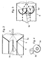
- the comfort nozzle 1 has a substantially horizontally arranged, rectangular air inlet surface 3 and a rectangular formed with semicircular short sides outlet opening 4 in the direction of the vehicle interior, wherein the air upstream side of the comfort nozzle 1 flaps 5 are arranged to the air distribution to the diffuse region and the beam region of To regulate comfort nozzle 1 and the total air mass flow, and a grill (not shown) is arranged on the air outlet side to protect the comfort nozzle 1, if necessary, to direct the air flow and optically adjust the opening to the adjacent areas.
- the arranged in the end region of an air channel 2 comfort nozzle 1 comprises a metering device 6, which is formed by the flaps 5 in conjunction with walls of the comfort nozzle 1, which will be explained in more detail below, and a spoiler 7, which is downstream of the metering device 6.
- the metering device 6 is formed by a flap arrangement, consisting of three flaps 5, which a targeted air distribution to the individual sub-channels of the air guide device 7 described in more detail later the comfort nozzle 1 allows.
- the metering device 6 is in particular in the FIGS. 1 and 2 shown in more detail, the FIGS. 3 and 4 show the kinematics of Dosiervonichtung 6.
- the control is performed by the occupant via a (not shown) dashboard actuator, in this case a knob, which is directly connected to a shaft of the metering device 6.
- the air channel 2 ends in a rectangular shape, wherein the cross section is divided in the longitudinal direction of the rectangle by two partitions into three subregions, wherein the central portion is formed slightly larger than the two outer portions.
- two outer flaps 5a are arranged, which are designed as single-leaf flaps, wherein the pivot axes S of these outer flaps 5a extends along the end of the corresponding partition wall.
- the third, middle flap 5b is designed as a mirror-image Schmettedingsklappe substantially with respect to its pivot axis S. All three flaps 5 have mutually parallel pivot axes S.
- the pivoting movements of the two outer flaps 5a are opposite, mirror-inverted to the central longitudinal plane, wherein the maximum pivoting angle in the present case is slightly less than 90 °.
- the angle occupied by the flap filaments to the surface of the dividing wall in the present case is somewhat smaller than in the outer end position.
- the flap surfaces in the outer end position close the two outer portions of the air channel 2 and in its central end position the central portion of the air channel 2.
- the middle flap 5b is arranged so far offset in the central portion of the air channel 2 in the air flow direction that no overlaps the movement ranges of the flaps 5 result.
- the pivoting angle of the middle flap 5c is in the present case a maximum of about 50 °.
- the flap position is made possible by means of a relatively simple kinematics, wherein the two shafts of the outer flaps 5a are provided with tooth segments 5a 'which mesh with one another.
- the shaft of the middle flap 5b is provided with a toothed segment 5b ', wherein on the toothed segment 5b' a freewheeling surface is provided to enable the middle flap 5b a certain freewheel, ie the middle flap 5b remains fully open, while the outer flaps Move 5a.
- Such gear arrangements are for example in the DE 103 46 539 A1 described in more detail, the disclosure of which is expressly included in relation to possible movement sequences of the flaps 5.
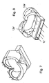
- FIGS. 5 to 11 seen in the air flow direction behind the metering device 6 arranged air guide 7 of the comfort nozzle 1 explained in more detail.
- the spoiler 7 of the comfort nozzle 1 is designed such that at its inlet region 10, which is then arranged on the metering device 6, through the above-mentioned partitions, a division of the air duct 2 in said three sections, hereinafter also as sub-channels 11, 12 'and 12 ", takes place (see, eg Fig. 6 ). In this case, no change in direction with respect to the direction of the air duct 2 is provided in the initial region, also referred to as entry region of the air guiding device 7.
- a second division of the subducts 11, 12 'and 12 is provided in each case, whereby this time the division takes place perpendicularly to the previous subdivision, but not necessarily in the same plane as seen in the longitudinal direction of the comfort nozzle 1
- the division of the middle sub-channel 11 into two sub-channels 11 a and 11 b.
- the respective rectangular sub-channels 11 a and 11 b are converted into a circular cross-section, each of the sub-channels 11 a and 11 b ends in a cylindrical region (see eg Fig. 5 ).
- the two other sub-channels 12 'and 12 are divided into sub-channels 12a', 12b 'and 12a", 12b ", wherein the sub-channels extend partially helically around the cylindrical portions of the inner sub-channels 11a and 11b (see Fig. 8 and Fig. 9 ).
- a directed flow results for the two inner sub-channels 11 a and 11 b, while for the outer sub-channels 12 a ', 12 a "an anticlockwise directed, helical flow pattern and for the other outer sub-channels 12b 'and 12b "a directed clockwise, helical flow pattern results.
- the function of the comfort nozzle 1 is the following: is the metering device 6 in a position that releases both sub-channels 11 and 12, so each passes an approximately equal air flow in the sub-channels 11, 12 'and 12 "and further in the sub-channels 11a, 11th b, 12a ', 12a ", 12b' and 12b.”
- the air flowing through the inner sub-channels 11a, 11b passes directly through the comfort nozzle 1 and is discharged into the vehicle interior in a substantially straight direction and with a sufficiently uniform flow profile.
- the air flowing through the outer partial channels 12a ', 12a ", 12b' and 12b" is deflected by the helical curves and thereby obtain a twist which is still present at the outlet opening 4 and provides for a certain turbulence of the air and the respective through the inner sub-channels 11a and 11b fan out coming streams of air.
- the air passes exclusively through the outer subchannels 12 a', 12a ", 12b 'and 12b" of the spoiler 7 and thereby receives the above-mentioned twist, which is still present at the outlet opening 4 and provides for a strong turbulence of the air (diffuse setting).
- Air outlet side can be provided - instead of the said grill - an adjustable fin arrangement, which deflects the spot beam if necessary, or slightly deflects a diffuse beam.
Landscapes
- Physics & Mathematics (AREA)
- Thermal Sciences (AREA)
- Engineering & Computer Science (AREA)
- Mechanical Engineering (AREA)
- Air-Conditioning For Vehicles (AREA)
- Duct Arrangements (AREA)
Abstract
Description
Die Erfindung betrifft eine Komfortdüse gemäß dem Oberbegriff des Anspruchs 1.The invention relates to a comfort nozzle according to the preamble of claim 1.
Aus der
Derartige Ausgestaltungen lassen jedoch noch Wünsche offen.However, such embodiments still leave something to be desired.
Es ist Aufgabe der Erfindung, eine verbesserte Komfortdüse zur Verfügung zu stellen.It is an object of the invention to provide an improved comfort nozzle available.
Diese Aufgabe wird gelöst durch eine Komfortdüse mit den Merkmalen des Anspruchs 1. Vorteilhafte Ausgestaltungen sind Gegenstand der Unteransprüche.This object is achieved by a comfort nozzle with the features of claim 1. Advantageous embodiments are the subject of the dependent claims.
Erfindungsgemäß ist eine Komfortdüse vorgesehen, die mindestens eine Luftleitvorrichtung, welche den Luftkanal in mehrere Teilluftkanäle aufteilt, wobei ein Teilluftkanal für einen Spotstrahl und mindestens ein anderer Teilluftkanal für einen diffusen Luftaustritt aus der Komfortdüse ausgebildet ist, und eine Dosiervorrichtung aufweist, mittels welcher die Luftverteilung auf die einzelnen Teilluftkanäle erfolgt, wobei die Dosiervorrichtung drei Klappen mit parallelen Schwenkachsen aufweist, und die äußeren Klappen einflügelige Klappen sind. Eine derartige Komfortdüse kann eine einfache Kinematik für die einzelnen Düsenstellungen, nämlich Spotstrahl, diffuser Strahl und Zwischenstellungen, sowie Absperrfunktion hiervon, sowie eine Absperrfunktion aufweisen. Mittels dieser Kinematikanordnung können die genannten Einstellungen durch Einstellung der entsprechenden Klappen realisiert werden. Das Vorsehen der bisher üblichen zwei Kurvenscheiben für die Regelung des Spotstrahls kann entfallen, insbesondere wenn die den einzelnen Klappen zugehörende Wellen über Zahnsegmente miteinander gekoppelt sind, und zumindest ein Zahnsegment mit einer Freilauffläche vorgesehen ist.According to the invention, a comfort nozzle is provided which has at least one air guiding device which divides the air duct into a plurality of partial air ducts, a partial air duct for a spot jet and at least one other partial air duct for a diffuse air outlet being formed from the comfort nozzle, and a dosing device by means of which the air distribution the individual partial air channels takes place, wherein the metering device has three flaps with parallel pivot axes, and the outer flaps are single-leaf flaps. Such a comfort nozzle can have a simple kinematics for the individual nozzle positions, namely spot beam, diffuse jet and intermediate positions, as well as a shut-off function thereof, as well as a shut-off function. By means of this kinematics arrangement, the settings mentioned can be realized by adjusting the corresponding flaps. The provision of the usual two cams for the control of the spot beam can be omitted, especially if the individual flaps belonging waves are coupled together via tooth segments, and at least one toothed segment is provided with a freewheeling surface.
Bei der mittleren Klappe handelt es sich besonders bevorzugt um eine zweiflügelige Klappe mit zentraler Schwenkachse.The middle flap is particularly preferably a two-leaf flap with a central pivot axis.
Die äußeren Klappen weisen vorzugsweise entgegen der Luftanströmrichtung weisende Klappenflächen auf, welche um einen Winkel von vorzugsweise weniger als 180°, insbesondere weniger als 120°, und ganz besonders bevorzugt von ca. 90° +/- 20° verschwenkbar sind.The outer flaps preferably have flap surfaces pointing counter to the air inflow direction, which can be swiveled through an angle of preferably less than 180 °, in particular less than 120 °, and very particularly preferably of approximately 90 ° +/- 20 °.
Die äußeren Klappen sind bevorzugt in einer Endstellung mit ihren von den Schwenkachsen beabstandeten Enden aneinander anliegend angeordnet, d.h. die Klappenflächen sind V-förmig angeordnet. Dies verbessert die Luftverteilung und sorgt für relativ geringe Strömungswiderstände durch die Klappen.The outer flaps are preferably disposed adjacent one another in an end position with their ends spaced from the pivot axes, i. the flap surfaces are arranged in a V-shape. This improves the air distribution and ensures relatively low flow resistance through the flaps.
Vorzugsweise sind die beiden äußeren Klappen der Dosiervorrichtung mit ihren Schwenkachsen am luftanströmseitigen Ende je einer Trennwand angeordnet. Die Trennwand bildet hierbei bevorzugt bereits einen Einströmbereich zur nachfolgend angeordneten Luftleitvorrichtung.Preferably, the two outer flaps of the metering device are arranged with their pivot axes at the air inlet end of a respective partition. In this case, the dividing wall preferably already forms an inflow region for the subsequently arranged air-guiding device.
Die mittlere Klappe ist vorzugsweise um einen Winkel von weniger als 90° verschwenkbar, insbesondere bevorzugt in einem Winkel von weniger als 60°. Der Schwenkwinkel beträgt vorzugsweise 45° +/- 15°. Ein kleiner Schwenkwinkel lässt sich durch eine entsprechende Kopplung mit den äußeren Klappen einfacher realisieren als ein 90° Winkel.The middle flap is preferably pivotable through an angle of less than 90 °, in particular preferably at an angle of less than 60 °. The swivel angle is preferably 45 ° +/- 15 °. A small swivel angle can be realized more easily by a corresponding coupling with the outer flaps than a 90 ° angle.
Vorzugsweise ist die mittlere Klappe am Beginn des Teilkanals angeordnet, welcher einem Spotstrahl der Komfortdüse zugeordnet ist. Dies ermöglicht einen möglichst geradlinigen Strömungsverlauf, so dass der Luftwiderstand gering gehalten und die durch Umlenkungen bewirkten Verwirbelungen minimiert werden können.Preferably, the middle flap is arranged at the beginning of the sub-channel, which is associated with a spot jet of the comfort nozzle. This allows a streamlined flow path as possible, so that the air resistance kept low and the turbulence caused by deflections can be minimized.
Die äußeren Klappen sind vorzugsweise am Beginn von Teilkanälen angeordnet, welche einem diffusen Strahl der Komfortdüse zugeordnet sind. Da diese äußeren Teilkanäle üblicherweise mehr umgelenkt werden müssen, kann die Umlenkung mit der Drallerzeugung verbunden werden.The outer flaps are preferably arranged at the beginning of subchannels which are associated with a diffuse jet of the comfort nozzle. Since these outer sub-channels usually have to be deflected more, the deflection can be connected to the swirl generation.
Der Luftkanal, welcher die beispielsweise von einer Klimaanlage kommende Luft der Komfortdüse zuführt, ist vorzugsweise mit einem rechteckförmigen Querschnitt endend ausgebildet, in welchem die Dosiervorrichtung angeordnet ist.The air duct, which feeds the coming example of an air conditioner air comfort nozzle, is preferably with a rectangular Cross-section formed formed in which the metering device is arranged.
Im Folgenden wird die Erfindung anhand eines Ausführungsbeispiels unter Bezugnahme auf die Zeichnung im Einzelnen erläutert. In der Zeichnung zeigen:
- Fig. 1
- eine Ansicht von hinten auf eine Komfortdüse gemäß dem Ausführungsbeispiel,
- Fig. 2
- einen Schnitt durch die Komfortdüse von
Fig. 1 entlang der Linie II-II, - Fig. 3
- eine Seitenansicht in Richtung des Pfeiles III von
Fig. 1 mit angedeuteten Zahnrädern und gestrichelt dargestellten Klappen, . - Fig. 4
- eine Detailansicht der die Klappen koppelnden Zahnräder von
Fig. 3 , - Fig. 5
- eine perspektivische Ansicht der Luftleitvorrichtung, wie sie in der Komfortdüse von
Fig. 1 verwendet wird, - Fig. 6
- eine andere perspektivische Ansicht der Luftleitvorrichtung von
Fig. 5 , - Fig. 7
- eine erste perspektivische Ansicht eines Teils der Luftleitvorrichtung von
Fig. 5 , - Fig. 8
- eine andere perspektivische Darstellung des Teils der Luftleitvonichtung von
Fig. 7 , - Fig. 9
- eine erste perspektivische Darstellung eines zweiten Teils der Luftleitvorrichtung von
Fig. 5 , - Fig. 10
- eine andere perspektivische Darstellung des Teils der Luftleitvorrichtung von
Fig. 9 , und - Fig. 11
- eine perspektivische Darstellung eines dritten Teils der Luftleitvorrichtung von
Fig. 5 .
- Fig. 1
- a view from the rear of a comfort nozzle according to the embodiment,
- Fig. 2
- a section through the comfort nozzle of
Fig. 1 along the line II-II, - Fig. 3
- a side view in the direction of arrow III of
Fig. 1 with indicated gears and dashed flaps,. - Fig. 4
- a detailed view of the flaps coupling the gears of
Fig. 3 . - Fig. 5
- a perspective view of the air deflector, as in the comfort of
Fig. 1 is used, - Fig. 6
- another perspective view of the spoiler of
Fig. 5 . - Fig. 7
- a first perspective view of a portion of the spoiler of
Fig. 5 . - Fig. 8
- another perspective view of the part of the Luftleitvonichtung of
Fig. 7 . - Fig. 9
- a first perspective view of a second part of the spoiler of
Fig. 5 . - Fig. 10
- another perspective view of the part of the spoiler of
Fig. 9 , and - Fig. 11
- a perspective view of a third part of the spoiler of
Fig. 5 ,
Eine Komfortdüse 1, wie sie als Ausströmer eines Kraftfahrzeug-Belüftungssystems verwendet wird, ist im Endbereich eines Luftkanals 2 angeordnet. Die Komfortdüse 1 weist eine im Wesentlichen horizontal angeordnete, rechteckige Lufteintrittsfläche 3 und eine rechteckförmige mit halbkreisförmig ausgebildeten kurzen Seiten ausgebildete Austrittsöffnung 4 in Richtung Fahrzeuginnenraum auf, wobei luftanströmseitig der Komfortdüse 1 Klappen 5 angeordnet sind, um die Luftverteilung auf den diffusen Bereich und den Strahlbereich der Komfortdüse 1 sowie den Gesamtluftmassenstrom zu regeln, und luftaustrittsseitig ein Grill (nicht dargestellt) angeordnet ist, um die Komfortdüse 1 zu schützen, ggf. noch die Luftströmung zu richten und die Öffnung optisch an die benachbarten Flächen anzupassen.A comfort nozzle 1, as used as a vent of a motor vehicle ventilation system, is arranged in the end region of an
Die im Endbereich eines Luftkanals 2 angeordnete Komfortdüse 1 umfasst eine Dosiervorrichtung 6, welche durch die Klappen 5 in Verbindung mit Wänden der Komfortdüse 1 gebildet wird, auf die nachfolgend näher erläutert wird, und eine Luftleitvorrichtung 7, welche der Dosiervorrichtung 6 nachgeordnet ist.The arranged in the end region of an
Die Dosiervorrichtung 6 ist durch eine Klappenanordnung, bestehend aus drei Klappen 5 gebildet, welche eine gezielte Luftverteilung auf die einzelnen Teilkanäle der an späterer Stelle näher beschriebenen Luftleitvorrichtung 7 der Komfortdüse 1 ermöglicht. Die Dosiervorrichtung 6 ist insbesondere in den
Der Luftkanal 2 endet rechteckförmig, wobei der Querschnitt in Längsrichtung des Rechtecks durch zwei Trennwände in drei Teilbereiche unterteilt ist, wobei der mittlere Teilbereich etwas größer ausgebildet ist als die beiden äußeren Teilbereiche. Am luftkanalseftigen Ende der Trennwände sind zwei äußere Klappen 5a angeordnet, die als einflügelige Klappen ausgebildet sind, wobei die Schwenkachsen S dieser äußeren Klappen 5a entlang des Endes der entsprechenden Trennwand verläuft. Die dritte, mittlere Klappe 5b ist als im Wesentlichen bezüglich ihrer Schwenkachse S spiegelbildliche Schmettedingsklappe ausgebildet. Alle drei Klappen 5 weisen parallel zueinander verlaufende Schwenkachsen S auf. Die Schwenkbewegungen der beiden äußeren Klappen 5a verlaufen entgegengesetzt, spiegelbildlich zur Mittellängsebene, wobei der maximale Schwenkwinkel vorliegend etwas weniger als 90° beträgt. In der mittleren Endstellung ist der Winkel, den die Klappenfilächen zur Fläche der Trennwand einnehmen vorliegend etwas kleiner als in der äußeren Endstellung. Hierbei verschließen die Klappenflächen in der äußeren Endstellung die beiden äußeren Teilbereiche des Luftkanals 2 und in ihrer mittleren Endstellung den mittleren Teilbereich des Luftkanals 2. Die mittlere Klappe 5b ist so weit in den mittleren Teilbereich des Luftkanals 2 in Luftströmungsrichtung versetzt angeordnet, dass sich keine Überschneidungen der Bewegungsbereiche der Klappen 5 ergeben. Der Schwenkwinkel der mittleren Klappe 5c beträgt vorliegend maximal ca. 50°.The
Die Klappenstellung wird mittels einer relativ einfachen Kinematik ermöglicht, wobei die beiden Wellen der äußeren Klappen 5a mit Zahnsegmenten 5a' versehen sind, die miteinander kämmen. Die Welle der mittleren Klappe 5b ist mit einem Zahnsegment 5b' versehen, wobei am Zahnsegment 5b' eine Freilauffläche vorgesehen ist, um der mittleren Klappe 5b einen gewissen Freilauf zu ermöglichen, d.h. die mittlere Klappe 5b bleibt hierbei vollständig geöffnet, während sich die äußeren Klappen 5a bewegen. Derartige Getriebeanordnungen sind beispielsweise in der
Im Folgenden wird unter Bezugnahme auf die
Die Luftleitvorrichtung 7 der Komfortdüse 1 ist derart ausgebildet, dass an ihrem Eintrittsbereich 10, der anschließend an die Dosiervorrichtung 6 angeordnet ist, durch die oben genannten Trennwände eine Aufteilung des Luftkanals 2 in besagte drei Teilbereiche, im Folgenden auch als Teilkanäle 11, 12' und 12" bezeichnet, erfolgt (siehe z.B.
Im Anschluss an den Eintrittsbereich der Luftleitvorrichtung 7 ist jeweils eine zweite Aufteilung der Teilkanäle 11, 12' und 12" vorgesehen, wobei diesmal die Aufteilung senkrecht zur vorigen Aufteilung erfolgt, allerdings nicht notwendigerweise in der in Längsrichtung der Komfortdüse 1 gesehen gleichen Ebene. Hierbei erfolgt zuerst die Aufteilung des mittleren Teilkanals 11 in zwei Teilkanäle 11 a und 11b. Die jeweils rechteckförmigen Teilkanäle 11a und 11b werden in einen kreisförmigen Querschnitt übergeführt, wobei jeder der Teilkanäle 11a und 11 b in einem zylinderförmigen Bereich endet (siehe z.B.
Auf Grund der entgegengesetzt gerichteten wendelartigen Strömungsverläufe wird die durch die äußeren Teilkanäle 12a', 12a", 12b', 12b" kommende Luft mit einem Drall versehen, während die durch die inneren Teilkanäle 11a und 11 b kommende Luft diese gerade durchläuft und gerade ausströmt.Due to the oppositely directed helical flow paths, the air coming through the
Die Funktion der Komfortdüse 1 ist Folgende: steht die Dosiervorrichtung 6 in einer Stellung, die beide Teilkanäle 11 und 12 freigibt, so gelangt jeweils ein etwa gleich großer Luftstrom in die Teilkanäle 11, 12' und 12" und weiter in die Teilkanäle 11a, 11 b, 12a', 12a", 12b' und 12b". Die die inneren Teilkanäle 11a, 11 b durchströmende Luft gelangt auf direktem Wege durch die Komfortdüse 1 und wird in im Wesentlichen gerader Richtung und mit einem ausreichend gleichmäßigen Strömungsprofil in den Fahrzeuginnenraum abgegeben. Die die äußeren Teilkanäle 12a', 12a", 12b' und 12b" durchströmende Luft wird durch die wendelartigen Verläufe umgelenkt und erhalten dadurch einen Drall, der auch an der Austrittsöffnung 4 noch vorhanden ist und für eine gewisse Verwirbelung der Luft sorgt und die jeweiligen durch die inneren Teilkanäle 11a und 11b kommenden Luftströme auffächert.The function of the comfort nozzle 1 is the following: is the
Verschließen die äußeren Klappen 5a die äußeren Teilbereiche und somit die äußeren Teilkanäle 12' und 12" und ist der innere Teilbereich bzw. Teilkanal 11 freigegeben, so gelangt die Luft ausschließlich durch die inneren Teilkanäle 11 a und 11 b zur Austrittsöffnung 4, so dass ein im Wesentlichen drallfreier Luftstrahl an den Fahrzeuginnenraum abgegeben wird (Spotwirkung).Close the
Verschließen hingegen die äußeren Klappen 5a in Verbindung mit der inneren Klappe 5b der Dosiervorrichtung 6 den inneren Teilbereich bzw. Teilkanal 11 und sind die äußeren Teilbereiche bzw. Teilkanäle 12' und 12" freigegeben, so gelangt die Luft ausschließlich durch die äußeren Teilkanäle 12a', 12a", 12b' und 12b" der Luftleitvorrichtung 7 und erhält dadurch den o.g. Drall, der auch an der Austrittsöffnung 4 noch vorhanden ist und für eine starke Verwirbelung der Luft sorgt (diffuse Einstellung).On the other hand, if the
Zwischenbereiche können beliebig angesteuert werden, so dass eine feine Dosierung des Luftstromes mit Hilfe der Komfortdüse 1 möglich ist.Intermediate areas can be controlled as desired, so that a fine dosing of the air flow with the aid of the comfort nozzle 1 is possible.
Luftaustrittsseitig kann - an Stelle des besagten Grills - eine einstellbare Lamellenanordnung vorgesehen sein, welche den Spotstrahl ggf. umlenkt oder einen diffusen Strahl geringfügig ablenkt.Air outlet side can be provided - instead of the said grill - an adjustable fin arrangement, which deflects the spot beam if necessary, or slightly deflects a diffuse beam.
Claims (13)
Applications Claiming Priority (1)
| Application Number | Priority Date | Filing Date | Title |
|---|---|---|---|
| DE102007019682A DE102007019682A1 (en) | 2007-04-24 | 2007-04-24 | comfort vent |
Publications (3)
| Publication Number | Publication Date |
|---|---|
| EP1985482A2 true EP1985482A2 (en) | 2008-10-29 |
| EP1985482A3 EP1985482A3 (en) | 2009-03-04 |
| EP1985482B1 EP1985482B1 (en) | 2012-11-28 |
Family
ID=39272716
Family Applications (1)
| Application Number | Title | Priority Date | Filing Date |
|---|---|---|---|
| EP20080004744 Not-in-force EP1985482B1 (en) | 2007-04-24 | 2008-03-14 | Air outlet |
Country Status (2)
| Country | Link |
|---|---|
| EP (1) | EP1985482B1 (en) |
| DE (1) | DE102007019682A1 (en) |
Cited By (4)
| Publication number | Priority date | Publication date | Assignee | Title |
|---|---|---|---|---|
| EP2062763A1 (en) * | 2007-11-26 | 2009-05-27 | Behr GmbH & Co. KG | Nozzle, especially for a vehicle |
| CN109955683A (en) * | 2019-03-13 | 2019-07-02 | 曼德电子电器有限公司 | Air conditioning exhausting gas circuit regulating mechanism |
| WO2019233877A1 (en) * | 2018-06-07 | 2019-12-12 | Bayerische Motoren Werke Aktiengesellschaft | Air vent for introducing air into a motor vehicle interior |
| CN112026489A (en) * | 2020-09-29 | 2020-12-04 | 奇瑞汽车股份有限公司 | Air outlet structure of automobile air conditioner |
Families Citing this family (5)
| Publication number | Priority date | Publication date | Assignee | Title |
|---|---|---|---|---|
| DE102009022740A1 (en) * | 2009-05-26 | 2010-12-02 | Behr Gmbh & Co. Kg | air vent device |
| DE102011075977A1 (en) * | 2011-05-17 | 2012-11-22 | Behr Gmbh & Co. Kg | Comfort nozzle, particularly for heating or air conditioning unit in motor vehicle, has spot-air channel and surrounding diffuse air ducts, and air inlet by rotational adjustment of spot flap |
| DE102011086229A1 (en) * | 2011-11-11 | 2013-05-16 | Behr Gmbh & Co. Kg | Air vent for ventilation system of vehicle, is provided with valve body having diffuse channel, a spot channel and guide device for controlling air flow through diffuse channel and spot channel |
| DE102012215686A1 (en) * | 2012-09-04 | 2014-03-06 | Behr Gmbh & Co. Kg | Direct spot-like air outlet for arranging in instrument panel for connecting with heating and/or air conditioning apparatus of motor car, has air reversing flaps arranged at inlet side, where air leaking characteristics are adjustable |
| DE102014208589A1 (en) * | 2014-05-07 | 2015-11-12 | Mahle International Gmbh | air vents |
Citations (2)
| Publication number | Priority date | Publication date | Assignee | Title |
|---|---|---|---|---|
| DE10346539A1 (en) | 2003-10-02 | 2005-04-21 | Behr Gmbh & Co Kg | Gear arrangement for an air control device, in particular for an air conditioning system of a motor vehicle |
| DE102004038016A1 (en) | 2003-08-11 | 2005-07-21 | Behr Gmbh & Co. Kg | Air vent for a motor vehicle comprises an air channel divided into cylindrical partial channels which are arranged parallel to each other, and an air deflecting device |
Family Cites Families (4)
| Publication number | Priority date | Publication date | Assignee | Title |
|---|---|---|---|---|
| DE10048529A1 (en) * | 2000-09-30 | 2002-04-11 | Volkswagen Ag | Device for setting air flow rates |
| DE10130951A1 (en) * | 2001-06-27 | 2003-01-23 | Behr Gmbh & Co | Air guiding device, in particular of a vehicle |
| DE10243974A1 (en) * | 2002-09-20 | 2004-04-01 | Behr Gmbh & Co. | Air filter, in particular for a motor vehicle |
| WO2005068232A1 (en) * | 2004-01-15 | 2005-07-28 | Behr Gmbh & Co. Kg | Method for regulating air nozzles for air-conditioning a motor vehicle |
-
2007
- 2007-04-24 DE DE102007019682A patent/DE102007019682A1/en not_active Withdrawn
-
2008
- 2008-03-14 EP EP20080004744 patent/EP1985482B1/en not_active Not-in-force
Patent Citations (2)
| Publication number | Priority date | Publication date | Assignee | Title |
|---|---|---|---|---|
| DE102004038016A1 (en) | 2003-08-11 | 2005-07-21 | Behr Gmbh & Co. Kg | Air vent for a motor vehicle comprises an air channel divided into cylindrical partial channels which are arranged parallel to each other, and an air deflecting device |
| DE10346539A1 (en) | 2003-10-02 | 2005-04-21 | Behr Gmbh & Co Kg | Gear arrangement for an air control device, in particular for an air conditioning system of a motor vehicle |
Cited By (8)
| Publication number | Priority date | Publication date | Assignee | Title |
|---|---|---|---|---|
| EP2062763A1 (en) * | 2007-11-26 | 2009-05-27 | Behr GmbH & Co. KG | Nozzle, especially for a vehicle |
| WO2019233877A1 (en) * | 2018-06-07 | 2019-12-12 | Bayerische Motoren Werke Aktiengesellschaft | Air vent for introducing air into a motor vehicle interior |
| CN111867859A (en) * | 2018-06-07 | 2020-10-30 | 宝马股份公司 | Air outflow device for introducing air into a motor vehicle interior |
| US11554632B2 (en) | 2018-06-07 | 2023-01-17 | Bayerische Motoren Werke Aktiengesellschaft | Air vent for introducing air into a motor vehicle interior |
| CN111867859B (en) * | 2018-06-07 | 2023-10-03 | 宝马股份公司 | Air outlet for introducing air into the interior of a motor vehicle |
| CN109955683A (en) * | 2019-03-13 | 2019-07-02 | 曼德电子电器有限公司 | Air conditioning exhausting gas circuit regulating mechanism |
| CN112026489A (en) * | 2020-09-29 | 2020-12-04 | 奇瑞汽车股份有限公司 | Air outlet structure of automobile air conditioner |
| CN112026489B (en) * | 2020-09-29 | 2022-03-15 | 奇瑞汽车股份有限公司 | Air outlet structure of automobile air conditioner |
Also Published As
| Publication number | Publication date |
|---|---|
| EP1985482A3 (en) | 2009-03-04 |
| DE102007019682A1 (en) | 2008-10-30 |
| EP1985482B1 (en) | 2012-11-28 |
Similar Documents
| Publication | Publication Date | Title |
|---|---|---|
| EP1985482B1 (en) | Air outlet | |
| EP1656271B1 (en) | Air vent, especially for a motor vehicle | |
| DE10219696B4 (en) | air outlet nozzle | |
| EP1902876B1 (en) | Air distribution case, in particular for a vehicle air conditioner, having a distribution valve and method of controlling such a distribution valve | |
| EP3403859A1 (en) | Air vent | |
| EP1542881B1 (en) | Air inlet, in particular for a motor vehicle | |
| DE202011102256U1 (en) | Air outlet device for a motor vehicle with a deflector | |
| EP3758964B1 (en) | Ventilation device for a motor vehicle | |
| EP1608522B1 (en) | Air exhausting device, in particular for a vehicle and corresponding method for exhausting air | |
| EP1800918B1 (en) | Air nozzle with vortex air flow | |
| DE102012015519A1 (en) | Air guide device for air discharging outlet for directing airflow from e.g. ventilation channel towards inner space of vehicle, has coupling and bearing axles spaced from each other such that slats are arranged at acute angle to each other | |
| EP1785298B1 (en) | Air nozzle | |
| DE102016121727A1 (en) | Ventilation device for vehicle | |
| DE102008021015A1 (en) | Arrangement for mixing gaseous media, e.g. air in vehicle air conditioning system, and blocking cross-section has first, second elements that interact to define different open cross-sections in channel; each is rotatable about fixed axis | |
| DE102019119732B4 (en) | Passenger traffic and motor vehicle | |
| DE102004039950A1 (en) | Air duct for use in vehicle comprises tube with outlets in its top, guide plate whose cross-section forms part of circle being mounted above outlets and directing air tangentially to produce Coanda effect | |
| EP1747109B1 (en) | Air outlet in particular for a motor vehicle | |
| EP2237979A1 (en) | Sound-dampening fluid channel having a flow guide element | |
| EP1972475A1 (en) | Air vent | |
| DE102008016238A1 (en) | Air nozzle for supplying air into inner area of vehicle i.e. motor vehicle, has ventilation flap that is positioned opposite to flow direction of air in position of flap partially based on axis of rotation | |
| EP1785299B1 (en) | Air nozzle | |
| EP1663682B1 (en) | Air vent, particularly for a motor vehicle | |
| DE102015206621A1 (en) | Air flow control unit | |
| DE102019131894B4 (en) | Control arrangement for an air vent | |
| EP1632375B1 (en) | Air outlet, in particular for a motor vehicle |
Legal Events
| Date | Code | Title | Description |
|---|---|---|---|
| PUAI | Public reference made under article 153(3) epc to a published international application that has entered the european phase |
Free format text: ORIGINAL CODE: 0009012 |
|
| AK | Designated contracting states |
Kind code of ref document: A2 Designated state(s): AT BE BG CH CY CZ DE DK EE ES FI FR GB GR HR HU IE IS IT LI LT LU LV MC MT NL NO PL PT RO SE SI SK TR |
|
| AX | Request for extension of the european patent |
Extension state: AL BA MK RS |
|
| PUAL | Search report despatched |
Free format text: ORIGINAL CODE: 0009013 |
|
| AK | Designated contracting states |
Kind code of ref document: A3 Designated state(s): AT BE BG CH CY CZ DE DK EE ES FI FR GB GR HR HU IE IS IT LI LT LU LV MC MT NL NO PL PT RO SE SI SK TR |
|
| AX | Request for extension of the european patent |
Extension state: AL BA MK RS |
|
| 17Q | First examination report despatched |
Effective date: 20091001 |
|
| 17P | Request for examination filed |
Effective date: 20090904 |
|
| AKX | Designation fees paid |
Designated state(s): AT BE BG CH CY CZ DE DK EE ES FI FR GB GR HR HU IE IS IT LI LT LU LV MC MT NL NO PL PT RO SE SI SK TR |
|
| GRAP | Despatch of communication of intention to grant a patent |
Free format text: ORIGINAL CODE: EPIDOSNIGR1 |
|
| GRAS | Grant fee paid |
Free format text: ORIGINAL CODE: EPIDOSNIGR3 |
|
| GRAA | (expected) grant |
Free format text: ORIGINAL CODE: 0009210 |
|
| AK | Designated contracting states |
Kind code of ref document: B1 Designated state(s): AT BE BG CH CY CZ DE DK EE ES FI FR GB GR HR HU IE IS IT LI LT LU LV MC MT NL NO PL PT RO SE SI SK TR |
|
| REG | Reference to a national code |
Ref country code: GB Ref legal event code: FG4D Free format text: NOT ENGLISH |
|
| REG | Reference to a national code |
Ref country code: CH Ref legal event code: EP |
|
| REG | Reference to a national code |
Ref country code: AT Ref legal event code: REF Ref document number: 585960 Country of ref document: AT Kind code of ref document: T Effective date: 20121215 |
|
| REG | Reference to a national code |
Ref country code: IE Ref legal event code: FG4D Free format text: LANGUAGE OF EP DOCUMENT: GERMAN |
|
| REG | Reference to a national code |
Ref country code: DE Ref legal event code: R096 Ref document number: 502008008733 Country of ref document: DE Effective date: 20130124 |
|
| REG | Reference to a national code |
Ref country code: NL Ref legal event code: VDEP Effective date: 20121128 |
|
| REG | Reference to a national code |
Ref country code: LT Ref legal event code: MG4D |
|
| PG25 | Lapsed in a contracting state [announced via postgrant information from national office to epo] |
Ref country code: ES Free format text: LAPSE BECAUSE OF FAILURE TO SUBMIT A TRANSLATION OF THE DESCRIPTION OR TO PAY THE FEE WITHIN THE PRESCRIBED TIME-LIMIT Effective date: 20130311 Ref country code: LT Free format text: LAPSE BECAUSE OF FAILURE TO SUBMIT A TRANSLATION OF THE DESCRIPTION OR TO PAY THE FEE WITHIN THE PRESCRIBED TIME-LIMIT Effective date: 20121128 Ref country code: NO Free format text: LAPSE BECAUSE OF FAILURE TO SUBMIT A TRANSLATION OF THE DESCRIPTION OR TO PAY THE FEE WITHIN THE PRESCRIBED TIME-LIMIT Effective date: 20130228 Ref country code: FI Free format text: LAPSE BECAUSE OF FAILURE TO SUBMIT A TRANSLATION OF THE DESCRIPTION OR TO PAY THE FEE WITHIN THE PRESCRIBED TIME-LIMIT Effective date: 20121128 Ref country code: SE Free format text: LAPSE BECAUSE OF FAILURE TO SUBMIT A TRANSLATION OF THE DESCRIPTION OR TO PAY THE FEE WITHIN THE PRESCRIBED TIME-LIMIT Effective date: 20121128 |
|
| PG25 | Lapsed in a contracting state [announced via postgrant information from national office to epo] |
Ref country code: PT Free format text: LAPSE BECAUSE OF FAILURE TO SUBMIT A TRANSLATION OF THE DESCRIPTION OR TO PAY THE FEE WITHIN THE PRESCRIBED TIME-LIMIT Effective date: 20130328 Ref country code: PL Free format text: LAPSE BECAUSE OF FAILURE TO SUBMIT A TRANSLATION OF THE DESCRIPTION OR TO PAY THE FEE WITHIN THE PRESCRIBED TIME-LIMIT Effective date: 20121128 Ref country code: GR Free format text: LAPSE BECAUSE OF FAILURE TO SUBMIT A TRANSLATION OF THE DESCRIPTION OR TO PAY THE FEE WITHIN THE PRESCRIBED TIME-LIMIT Effective date: 20130301 Ref country code: SI Free format text: LAPSE BECAUSE OF FAILURE TO SUBMIT A TRANSLATION OF THE DESCRIPTION OR TO PAY THE FEE WITHIN THE PRESCRIBED TIME-LIMIT Effective date: 20121128 Ref country code: LV Free format text: LAPSE BECAUSE OF FAILURE TO SUBMIT A TRANSLATION OF THE DESCRIPTION OR TO PAY THE FEE WITHIN THE PRESCRIBED TIME-LIMIT Effective date: 20121128 Ref country code: CY Free format text: LAPSE BECAUSE OF FAILURE TO SUBMIT A TRANSLATION OF THE DESCRIPTION OR TO PAY THE FEE WITHIN THE PRESCRIBED TIME-LIMIT Effective date: 20121128 |
|
| PG25 | Lapsed in a contracting state [announced via postgrant information from national office to epo] |
Ref country code: CZ Free format text: LAPSE BECAUSE OF FAILURE TO SUBMIT A TRANSLATION OF THE DESCRIPTION OR TO PAY THE FEE WITHIN THE PRESCRIBED TIME-LIMIT Effective date: 20121128 Ref country code: SK Free format text: LAPSE BECAUSE OF FAILURE TO SUBMIT A TRANSLATION OF THE DESCRIPTION OR TO PAY THE FEE WITHIN THE PRESCRIBED TIME-LIMIT Effective date: 20121128 Ref country code: EE Free format text: LAPSE BECAUSE OF FAILURE TO SUBMIT A TRANSLATION OF THE DESCRIPTION OR TO PAY THE FEE WITHIN THE PRESCRIBED TIME-LIMIT Effective date: 20121128 Ref country code: BG Free format text: LAPSE BECAUSE OF FAILURE TO SUBMIT A TRANSLATION OF THE DESCRIPTION OR TO PAY THE FEE WITHIN THE PRESCRIBED TIME-LIMIT Effective date: 20130228 Ref country code: DK Free format text: LAPSE BECAUSE OF FAILURE TO SUBMIT A TRANSLATION OF THE DESCRIPTION OR TO PAY THE FEE WITHIN THE PRESCRIBED TIME-LIMIT Effective date: 20121128 |
|
| PG25 | Lapsed in a contracting state [announced via postgrant information from national office to epo] |
Ref country code: NL Free format text: LAPSE BECAUSE OF FAILURE TO SUBMIT A TRANSLATION OF THE DESCRIPTION OR TO PAY THE FEE WITHIN THE PRESCRIBED TIME-LIMIT Effective date: 20121128 Ref country code: IT Free format text: LAPSE BECAUSE OF FAILURE TO SUBMIT A TRANSLATION OF THE DESCRIPTION OR TO PAY THE FEE WITHIN THE PRESCRIBED TIME-LIMIT Effective date: 20121128 Ref country code: RO Free format text: LAPSE BECAUSE OF FAILURE TO SUBMIT A TRANSLATION OF THE DESCRIPTION OR TO PAY THE FEE WITHIN THE PRESCRIBED TIME-LIMIT Effective date: 20121128 |
|
| BERE | Be: lapsed |
Owner name: BEHR G.M.B.H. & CO. KG Effective date: 20130331 |
|
| PLBE | No opposition filed within time limit |
Free format text: ORIGINAL CODE: 0009261 |
|
| STAA | Information on the status of an ep patent application or granted ep patent |
Free format text: STATUS: NO OPPOSITION FILED WITHIN TIME LIMIT |
|
| PG25 | Lapsed in a contracting state [announced via postgrant information from national office to epo] |
Ref country code: MC Free format text: LAPSE BECAUSE OF NON-PAYMENT OF DUE FEES Effective date: 20130331 |
|
| REG | Reference to a national code |
Ref country code: CH Ref legal event code: PL |
|
| 26N | No opposition filed |
Effective date: 20130829 |
|
| GBPC | Gb: european patent ceased through non-payment of renewal fee |
Effective date: 20130314 |
|
| PG25 | Lapsed in a contracting state [announced via postgrant information from national office to epo] |
Ref country code: HR Free format text: LAPSE BECAUSE OF FAILURE TO SUBMIT A TRANSLATION OF THE DESCRIPTION OR TO PAY THE FEE WITHIN THE PRESCRIBED TIME-LIMIT Effective date: 20121128 |
|
| REG | Reference to a national code |
Ref country code: DE Ref legal event code: R097 Ref document number: 502008008733 Country of ref document: DE Effective date: 20130829 |
|
| REG | Reference to a national code |
Ref country code: IE Ref legal event code: MM4A |
|
| PG25 | Lapsed in a contracting state [announced via postgrant information from national office to epo] |
Ref country code: IE Free format text: LAPSE BECAUSE OF NON-PAYMENT OF DUE FEES Effective date: 20130314 Ref country code: CH Free format text: LAPSE BECAUSE OF NON-PAYMENT OF DUE FEES Effective date: 20130331 Ref country code: BE Free format text: LAPSE BECAUSE OF NON-PAYMENT OF DUE FEES Effective date: 20130331 Ref country code: GB Free format text: LAPSE BECAUSE OF NON-PAYMENT OF DUE FEES Effective date: 20130314 Ref country code: LI Free format text: LAPSE BECAUSE OF NON-PAYMENT OF DUE FEES Effective date: 20130331 |
|
| REG | Reference to a national code |
Ref country code: AT Ref legal event code: MM01 Ref document number: 585960 Country of ref document: AT Kind code of ref document: T Effective date: 20130314 |
|
| PG25 | Lapsed in a contracting state [announced via postgrant information from national office to epo] |
Ref country code: MT Free format text: LAPSE BECAUSE OF FAILURE TO SUBMIT A TRANSLATION OF THE DESCRIPTION OR TO PAY THE FEE WITHIN THE PRESCRIBED TIME-LIMIT Effective date: 20121128 |
|
| PG25 | Lapsed in a contracting state [announced via postgrant information from national office to epo] |
Ref country code: AT Free format text: LAPSE BECAUSE OF NON-PAYMENT OF DUE FEES Effective date: 20130314 |
|
| REG | Reference to a national code |
Ref country code: DE Ref legal event code: R082 Ref document number: 502008008733 Country of ref document: DE Representative=s name: GRAUEL, ANDREAS, DIPL.-PHYS. DR. RER. NAT., DE |
|
| REG | Reference to a national code |
Ref country code: DE Ref legal event code: R082 Ref document number: 502008008733 Country of ref document: DE Representative=s name: GRAUEL, ANDREAS, DIPL.-PHYS. DR. RER. NAT., DE Effective date: 20150323 Ref country code: DE Ref legal event code: R081 Ref document number: 502008008733 Country of ref document: DE Owner name: MAHLE INTERNATIONAL GMBH, DE Free format text: FORMER OWNER: BEHR GMBH & CO. KG, 70469 STUTTGART, DE Effective date: 20150323 |
|
| PG25 | Lapsed in a contracting state [announced via postgrant information from national office to epo] |
Ref country code: TR Free format text: LAPSE BECAUSE OF FAILURE TO SUBMIT A TRANSLATION OF THE DESCRIPTION OR TO PAY THE FEE WITHIN THE PRESCRIBED TIME-LIMIT Effective date: 20121128 |
|
| PG25 | Lapsed in a contracting state [announced via postgrant information from national office to epo] |
Ref country code: HU Free format text: LAPSE BECAUSE OF FAILURE TO SUBMIT A TRANSLATION OF THE DESCRIPTION OR TO PAY THE FEE WITHIN THE PRESCRIBED TIME-LIMIT; INVALID AB INITIO Effective date: 20080314 Ref country code: LU Free format text: LAPSE BECAUSE OF NON-PAYMENT OF DUE FEES Effective date: 20130314 |
|
| REG | Reference to a national code |
Ref country code: FR Ref legal event code: PLFP Year of fee payment: 9 |
|
| PG25 | Lapsed in a contracting state [announced via postgrant information from national office to epo] |
Ref country code: IS Free format text: LAPSE BECAUSE OF FAILURE TO SUBMIT A TRANSLATION OF THE DESCRIPTION OR TO PAY THE FEE WITHIN THE PRESCRIBED TIME-LIMIT Effective date: 20121128 |
|
| REG | Reference to a national code |
Ref country code: FR Ref legal event code: PLFP Year of fee payment: 10 |
|
| REG | Reference to a national code |
Ref country code: FR Ref legal event code: PLFP Year of fee payment: 11 |
|
| PGFP | Annual fee paid to national office [announced via postgrant information from national office to epo] |
Ref country code: FR Payment date: 20190322 Year of fee payment: 12 |
|
| PGFP | Annual fee paid to national office [announced via postgrant information from national office to epo] |
Ref country code: DE Payment date: 20190404 Year of fee payment: 12 |
|
| REG | Reference to a national code |
Ref country code: DE Ref legal event code: R119 Ref document number: 502008008733 Country of ref document: DE |
|
| PG25 | Lapsed in a contracting state [announced via postgrant information from national office to epo] |
Ref country code: FR Free format text: LAPSE BECAUSE OF NON-PAYMENT OF DUE FEES Effective date: 20200331 Ref country code: DE Free format text: LAPSE BECAUSE OF NON-PAYMENT OF DUE FEES Effective date: 20201001 |