EP1985358B1 - System for homogenizing at least two solutions - Google Patents
System for homogenizing at least two solutions Download PDFInfo
- Publication number
- EP1985358B1 EP1985358B1 EP08251496A EP08251496A EP1985358B1 EP 1985358 B1 EP1985358 B1 EP 1985358B1 EP 08251496 A EP08251496 A EP 08251496A EP 08251496 A EP08251496 A EP 08251496A EP 1985358 B1 EP1985358 B1 EP 1985358B1
- Authority
- EP
- European Patent Office
- Prior art keywords
- solution
- assembly
- homogenizing
- applicator
- housing
- Prior art date
- Legal status (The legal status is an assumption and is not a legal conclusion. Google has not performed a legal analysis and makes no representation as to the accuracy of the status listed.)
- Ceased
Links
- 238000002156 mixing Methods 0.000 claims description 36
- 230000004913 activation Effects 0.000 claims description 21
- 230000003213 activating effect Effects 0.000 claims description 5
- 239000000243 solution Substances 0.000 description 79
- 239000000227 bioadhesive Substances 0.000 description 8
- 239000000853 adhesive Substances 0.000 description 6
- 230000001070 adhesive effect Effects 0.000 description 6
- 238000000034 method Methods 0.000 description 6
- 239000000203 mixture Substances 0.000 description 5
- XLYOFNOQVPJJNP-UHFFFAOYSA-N water Substances O XLYOFNOQVPJJNP-UHFFFAOYSA-N 0.000 description 5
- 230000000881 depressing effect Effects 0.000 description 4
- 238000004945 emulsification Methods 0.000 description 4
- 230000001804 emulsifying effect Effects 0.000 description 4
- 239000012530 fluid Substances 0.000 description 4
- 229920000642 polymer Polymers 0.000 description 4
- 239000000565 sealant Substances 0.000 description 4
- 230000000994 depressogenic effect Effects 0.000 description 3
- 238000000265 homogenisation Methods 0.000 description 3
- 239000011259 mixed solution Substances 0.000 description 3
- 230000009286 beneficial effect Effects 0.000 description 2
- 210000003813 thumb Anatomy 0.000 description 2
- 150000001298 alcohols Chemical class 0.000 description 1
- 239000011248 coating agent Substances 0.000 description 1
- 238000000576 coating method Methods 0.000 description 1
- 238000010276 construction Methods 0.000 description 1
- 210000003811 finger Anatomy 0.000 description 1
- 239000000463 material Substances 0.000 description 1
- 239000003921 oil Substances 0.000 description 1
- 235000011837 pasties Nutrition 0.000 description 1
- 238000006116 polymerization reaction Methods 0.000 description 1
- 229920002635 polyurethane Polymers 0.000 description 1
- 239000004814 polyurethane Substances 0.000 description 1
- 239000003381 stabilizer Substances 0.000 description 1
- 229910001220 stainless steel Inorganic materials 0.000 description 1
- 239000010935 stainless steel Substances 0.000 description 1
- 239000000126 substance Substances 0.000 description 1
- 230000008961 swelling Effects 0.000 description 1
- 229920002994 synthetic fiber Polymers 0.000 description 1
Images





Classifications
-
- B—PERFORMING OPERATIONS; TRANSPORTING
- B01—PHYSICAL OR CHEMICAL PROCESSES OR APPARATUS IN GENERAL
- B01F—MIXING, e.g. DISSOLVING, EMULSIFYING OR DISPERSING
- B01F27/00—Mixers with rotary stirring devices in fixed receptacles; Kneaders
- B01F27/27—Mixers with stator-rotor systems, e.g. with intermeshing teeth or cylinders or having orifices
-
- B—PERFORMING OPERATIONS; TRANSPORTING
- B01—PHYSICAL OR CHEMICAL PROCESSES OR APPARATUS IN GENERAL
- B01F—MIXING, e.g. DISSOLVING, EMULSIFYING OR DISPERSING
- B01F27/00—Mixers with rotary stirring devices in fixed receptacles; Kneaders
- B01F27/50—Pipe mixers, i.e. mixers wherein the materials to be mixed flow continuously through pipes, e.g. column mixers
-
- B—PERFORMING OPERATIONS; TRANSPORTING
- B01—PHYSICAL OR CHEMICAL PROCESSES OR APPARATUS IN GENERAL
- B01F—MIXING, e.g. DISSOLVING, EMULSIFYING OR DISPERSING
- B01F33/00—Other mixers; Mixing plants; Combinations of mixers
- B01F33/50—Movable or transportable mixing devices or plants
- B01F33/501—Movable mixing devices, i.e. readily shifted or displaced from one place to another, e.g. portable during use
- B01F33/5011—Movable mixing devices, i.e. readily shifted or displaced from one place to another, e.g. portable during use portable during use, e.g. hand-held
-
- B—PERFORMING OPERATIONS; TRANSPORTING
- B01—PHYSICAL OR CHEMICAL PROCESSES OR APPARATUS IN GENERAL
- B01F—MIXING, e.g. DISSOLVING, EMULSIFYING OR DISPERSING
- B01F35/00—Accessories for mixers; Auxiliary operations or auxiliary devices; Parts or details of general application
- B01F35/80—Forming a predetermined ratio of the substances to be mixed
- B01F35/88—Forming a predetermined ratio of the substances to be mixed by feeding the materials batchwise
- B01F35/882—Forming a predetermined ratio of the substances to be mixed by feeding the materials batchwise using measuring chambers, e.g. volumetric pumps, for feeding the substances
- B01F35/8822—Forming a predetermined ratio of the substances to be mixed by feeding the materials batchwise using measuring chambers, e.g. volumetric pumps, for feeding the substances using measuring chambers of the piston or plunger type
-
- B—PERFORMING OPERATIONS; TRANSPORTING
- B01—PHYSICAL OR CHEMICAL PROCESSES OR APPARATUS IN GENERAL
- B01F—MIXING, e.g. DISSOLVING, EMULSIFYING OR DISPERSING
- B01F2101/00—Mixing characterised by the nature of the mixed materials or by the application field
- B01F2101/2202—Mixing compositions or mixers in the medical or veterinary field
-
- B—PERFORMING OPERATIONS; TRANSPORTING
- B01—PHYSICAL OR CHEMICAL PROCESSES OR APPARATUS IN GENERAL
- B01F—MIXING, e.g. DISSOLVING, EMULSIFYING OR DISPERSING
- B01F2101/00—Mixing characterised by the nature of the mixed materials or by the application field
- B01F2101/2305—Mixers of the two-component package type, i.e. where at least two components are separately stored, and are mixed in the moment of application
-
- B—PERFORMING OPERATIONS; TRANSPORTING
- B05—SPRAYING OR ATOMISING IN GENERAL; APPLYING FLUENT MATERIALS TO SURFACES, IN GENERAL
- B05D—PROCESSES FOR APPLYING FLUENT MATERIALS TO SURFACES, IN GENERAL
- B05D1/00—Processes for applying liquids or other fluent materials
- B05D1/34—Applying different liquids or other fluent materials simultaneously
Definitions
- the present disclosure relates to systems for homogenizing and/or emulsifying two or more solutions prior to application, and more particularly, to an applicator system for emulsifying a polyurethane based adhesive/sealant and water prior to application.
- Bioadhesives are known in the art, as are various methods for applying the bioadhesive. Bioadhesives offer many significant advantages over conventional wound closure method, i.e., using sutures, staples, clips or other suitable mechanical fasteners. Bioadhesives are faster and simpler to apply, have a tendency to promote quicker wound closure with less scaring, and eliminate the need for a follow up visit to remove the mechanical fasteners.
- bioadhesives are composed of components that have a tendency to immediately activate and in some instances, rapidly polymerize when combined with one another. Because of this immediate activation and/or rapid polymerization of the bioadhesive, the components comprising the bioadhesive may not be combined until immediately prior to application.
- Conventional applicators for mixing the bioadhesive components prior to application generally include a mixing chamber or common conduit where the solutions are combined, i.e., mixed, as the solutions pass therethrough. The consistency of this mixture may vary depending on the types of solutions being combined, their quantities, and the speed at which the solutions pass through the mixing chamber.
- the components In an application requiring a homogenized solution, the components must be mixed separate from the applicator using a stand-alone or portable homogenizer, thus ensuring proper mixing.
- a surgeon When preparing the homogenized solution for application a surgeon is limited to mixing small amounts because once the solutions are combined, it may begin to harden. Any hardening prior to application may cause the applicator tip to clog and prevent an even application of the solution.
- U.S. Patent No 3,767,085 to Cannon et al. discloses such a device.
- the '085 patent discloses a double barrel carpule type syringe for the mixing of an elastomeric base material and an accelerator.
- the mixing syringe includes, on a distal end thereof, a common mixing and dispensing chamber provided with a rotary agitator driven from a motor on the syringe.
- the mixing syringe further includes a double plunger through which manual depression thereof results in the discharge of the fluids into the mixing and dispensing chamber.
- EP 1 099 470 discloses a device for mixing two pasty substances.
- the device of EP 1 099 470 includes a mixing element which is housed within the tubular portion of the housing of the device.
- EP 0 087 029 discloses a device for blending dental pastes so to enable prints to be made.
- the device of EP 0 087 029 includes a disposable agitator.
- an applicator system capable of mixing, homogenizing and/or emulsifying two or more solutions prior to application.
- a system for homogenizing two or more solutions as defined in claim 1 includes at least a first and a second source of solution, a hand held homogenizer having a homogenizing assembly, and an applicator assembly.
- the applicator assembly is configured to fluidly communicate the at least first and second sources of solution with the homogenizing assembly, wherein solution from each of the at least first and second source of solution is homogenized by the homogenizing assembly upon dispensing of the solution from the first and second sources of solution
- the first and second sources of solution may comprise syringes or metering pumps.
- the homogenizer may be configured to rotate the homogenizer assembly at about 1,000 to about 35,000 RPM, preferably 1,000 to 25,000 RPM.
- the applicator assembly may further be configured to include an outlet for dispensing a homogenized solution.
- the outlet may form an applicator tip for applying the homogenized solution.
- the outlet may instead form a connection for releasably securing a hose or tube.
- the homogenizing assembly may include rotors and stators.
- the homogenizing assembly may also be disposable.
- the applicator system may further include an activation mechanism for automatically supplying the solution from the first and second sources of solution.
- the activation mechanism may include a button or switch mounted on the applicator assembly.
- the applicator assembly may further include an activation mechanism for selectively releasing the solutions from the two or more sources of solution.
- the activation mechanism way include a dial for selectively activating the applicator assembly.
- the activation mechanism may include a motor.
- the method includes the steps of providing an applicator assembly having a housing configured for receiving two or more sources of solution, and a hand held homogenizer having a homogenizing assembly operably connected to the housing, wherein said housing is further configured to fluidly communicate each of said two or more sources of solution with said homogenizing assembly.
- the method further including the steps of providing two or more sources of solution, operably connecting said two or more sources of solution with said applicator assembly, dispensing solution from each of said two or more sources of solution into said housing, and activating said homogenizing assembly.
- FIG. 1 is a front, elevational view of the applicator system according to an embodiment of the present disclosure
- FIG. 2 is a side, elevational view of an applicator assembly and a first container of the applicator system of FIG. 1 ;
- FIG. 3 is a partial, cross-sectional, front, elevational view of the applicator assembly of the applicator system of FIGS. 1 and 2 ;
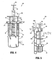
- FIG. 4 is a front, elevational view of an alternate embodiment of an applicator system according to the present disclosure.
- FIG. 5 is a partial, side, elevational view of an applicator and a first container of solution of the applicator system of FIG.. 4 ;
- FIG. 6 is a partial, cross-sectional, front, elevational view of the applicator system of FIGS. 4 and 5 ;
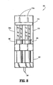
- FIG. 7 is a side, elevational view of another embodiment of the applicator system of the present disclosure.
- FIG. 8 is a front, elevational view of the applicator system of FIG. 7 ;
- FIG. 9 is a partial, longitudinal, cross-sectional side, elevational view of the applicator system of FIGS. 7 and 8 .
- the present disclosure relates particularly, to the emulsification and/or homogenization of a polymer adhesive and water
- aspects of the present disclosure can be incorporated into any apparatus, system or method where two or more solutions require mixing, homogenization, emulsification, or the like, prior to application.
- Embodiments of the presently disclosed applicator will now be described in detail with reference to the drawings in which like reference numerals designate identical or corresponding elements in each of the several views.
- distal refers to that portion of the instrument, or component thereof which is further from the user while the term “proximal” refers to that portion which is closer to the user.
- Applicator system 10 includes a hand-beld homogenizer 50, an applicator assembly 100 and two containers 60, 70 for selectively dispensing solution, e.g. syringes.
- applicator assembly 100 includes a housing 110, an arm 112 extending from housing 110, and a mount 114 fixedly attached to a distal end of arm 112.
- Mount 114 is configured to define openings 114a, 114b for selectively receiving respective syringes 60, 70 therein. Openings 114a, 114b may be configured to accommodate any number of solution containing vessels or sources, including, but not limited to, syringes, bottles, tubes and hoses.
- Mount 114 may be slideably supported within a longitudinal groove 112a defined in arm 112. In this manner, mount 114 may be selectively positioned along extension arm 112 as indicated by arrow "A".
- the spacing or distance between housing 110 and mount 114 may be adjusted to accommodate syringes or other vessels of varying dimensions.
- housing 110 includes first and second inlets 120, 122, respectively, an entrance conduit 124 fluidly interconnecting first and second inlets 120, 122, a mixing chamber 126 fluidly connected to entrance conduit 124, an exit conduit 128 fluidly connected to mixing chamber 126, and an outlet 130 fluidly connected to exit conduit 128.
- Housing 110 defines an opening 134 formed therein that is configured for selectively engaging and receiving a homogenizing assembly 56 of homogenizer 50.
- Inlets 120, 122 fluidly communicate with mixing chamber 126 via entrance conduit 124.
- Outlet 130 may be configured, as shown in FIGS. 1-3 , as a needle 132 for directly applying or dispensing of the homogenized solution to a target site. Outlet 130 may instead be configured for operable fluid engagement with a conduit, hose, tube or the like, for remotely applying the homogenized solution.
- Inlets 120, 122 of housing 110 may be configured for selective engagement with syringes 60, 70, respectively.
- Each inlet 120, 122 may include a threaded portion 120a, 122a for selectively receiving syringes 60, 70.
- Homogenizer 50 may be any known, commercially available portable homogenizer. Homogenizer 50 may operate at a single speed or may be capable of operating at variable speeds. Homogenizer 50 is preferably configured to operate in the range of about 1,000 to about 35,000 RPM, preferable 1,000-25000 RPM. Homogenizer 50 may be battery operated.
- homogenizer 50 includes a handle 52 housing a drive means, such as a motor 58, a drive shaft 54 extending from drive means 58, and a mixing homogenizing assembly 56 supported on a distal end of shaft 54.
- Homogenizing assembly 56 comprises rotors 56a and stators 56b.
- Rotors 56a and stators 56b may be made from stainless steel, polymers or the like.
- Homogenizing assembly 56 may include any number of rotors 56a and stators 56b in any configuration.
- Rotors 56a and stators 56b may be disposable, replaceable and/or sterilizable.
- Homogenizing assembly 56 of homogenizer 50 is rotatably mounted in mixing chamber 126 to homogenize the solutions introduced from syringes 60,70.
- Homogenizer 50 may include a lever, button or other suitable activation switch 52a for activating homogenizing assembly 56.
- syringes 60, 70 arc inserted through openings 114a, 114b of mount 114 and engageably coupled in threaded portions 120a, 122a of inlets 120, 122, respectively.
- homogenizer 50 may be activated. Depression of respective plungers 62, 72 of syringes 60, 70 causes the individual solutions contained within each syringe 60, 70 to be expelled into inlets 120, 122, respectively, and received within or advanced into entrance conduit 124.
- the individual solutions from syringes 60, 70 are first combined in entrance conduit 124 to form a solution mix before being introduced or advanced into mixing chamber 126.
- homogenizing assembly 56 causes the further mixing, homogenization, emulsification or the like, of the solution mix to form a homogenized solution.
- the resulting homogenized solution is further advanced through mixing chamber 126 and through exit conduit 128 before being forced out through outlet 130.
- the independent configuration of syringes 60,70 permit a user to adjusted the amount of solution expelled from each syringe 60, 70 as necessary to provide a homogenized solution of proper concentration exiting outlet 130.
- Equal amounts of each solution may be dispersed by depressing plungers 62, 72 equal amounts. Depressing the plunger of one syringe more than another will result in a higher concentration of that individual solution in the resulting homogenized solution.
- the rate of which the individual solutions are dispersed, and thus the rate at which the homogenized solution exits through outlet 130 may also be varied. For example, the greater the force applied to plungers 62, 72, the faster the homogenized solution will exit outlet 130.
- Syringes 60, 70 may include markings or gradations 64, 74 for determining the amount of solution being introduced into housing 110 of applicator system 100.
- Syringes 60, 70 may instead be replaced by a metering pump, such as syringe pump, diaphragm pump, gear pump or the like, for selectively supplying or delivering solution to inlets 120, 122 of housing 110.
- the solutions supplied to inlets 120, 122 may be permitted to flow without any external pressure, i.e. depression of a plunger.
- the rotation of homogenizing assembly 56 creates a suction that may draw the solutions from within containers or syringes 60, 70 into mixing chamber 126 and expels the homogenized solution through outlet 130.
- the rate of flow may be varied by adjusting the speed at which the homogenizing assembly 56 rotates or by modifying the configuration of mixing chamber 126.
- Applicator assembly 200 includes first and second containers or syringes 80, 90. Applicator assembly 200 is substantially similar to applicator assembly 100 and thus will only be discussed herein to the extent necessary to identify differences in construction and operation.
- Applicator assembly 200 includes a housing 210, an arm 212 extending from housing 210 and a mount 214 selectively positionable about arm 212.
- Mount 214 may be slidably supported within a longitudinal groove 2 12a defined in arm 212. In this manner, mount 214 may be electively positioned along arm 212 as indicated by arrow "B".
- the proximal end of arm 212 is further configured to receive an activation mechanism 230 for selectively dispersing the solutions from syringes 80, 90 into housing 210 of applicator assembly 200.
- Activation mechanism 230 includes a dial 232 supported on arm 212 and a plunger assembly 234.
- Plunger assembly 234 includes an elongated member 234a having teeth 234b along a length thereof, a button or tab 235 supported on elongated member 234a for activating activation mechanism 230, and a planar member 236 supported on elongated member 234 for engaging plungers 82, 92 of syringes 80, 90.
- a proximal end of extension arm 212 is configured to slidable receive and support elongated member 234.
- Dial 232 is rotatably mounted within the proximal end of extension arm 212 and including teeth 232a is configured to engage teeth 234a of elongated member 234.
- housing 210 includes first and second inlets 220, 222, respectively, an entrance conduit 224 fluidly interconnecting the first and second inlets 220. 222, a mixing chamber 226 fluidly connected to entrance conduit 224, an exit conduit 228 fluidly connected to mixing chamber 226, and an outlet 230 fluidly connected to exit conduit 228.
- Mixing chamber 226 is configured to include a homogenizing assembly 256.
- Homogenizing assembly 256 comprises a shaft 254, and rotors 256a and stators 256b securely affixed to shaft 255.
- Homogenizing assembly 256 is configured to be maintained with housing 210.
- Housing 210 further defines an opening 234 configured for selectively engaging a homogenizing motor.
- the proximal end of shaft 254 is configured for operable engagement with a shaft 255 extending from the homogenizing motor to rotate homogenizing assembly 256.
- homogenizing motors of various speeds and configurations may be interchangeably connected to housing 210 of applicator assembly 200 to rotate homogenizing assembly 256.
- Applicator assembly 200 may be disposable, replaceable and/or sterilizable.
- Applicator system 300 includes a housing 310 configured and adapted to selectively receive and support first and second containers of solution 360, 370, a homogenizing motor 350 supported on housing 310, a homogenizing assembly 356 extending from motor 350 and housing 310, and an applicator assembly 320 supported on housing 310 and configured to receive homogenizing assembly 356.
- Housing 310 includes a base 310a for encasing homogenizer motor 350, a cover 310b selectively supportable on base 310a for accessing and replacing homogenizing motor 350, and a handle assembly 310c extending from base 310a for providing a secure grip for applicator system 300.
- Base 310a is further configured to selectively retain first and second containers of solution 360, 370.
- a button or lever 314 is slidably mounted within grooves 314a of base 310a and is configured to simultaneously depress plungers 362, 372 of first and second containers 360, 370.
- Button 314 is positioned such that button 314 may be depressed using the thumb of the hand that is gripping handle assembly 310c, thus enabling single handed operation of applicator system 300.
- the rate at which button 314 is depressed may function to control the rate at which the homogenized solution is dispensed.
- Applicator assembly 320 is operably connected to housing 310 and each of first and second containers 360, 370. Applicator assembly 320 may be integrally formed with housing 310 or may instead be selectively attachable/detachable thereto. In this manner, applicator assembly 320 may be replaced between uses or as deemed necessary by a surgeon.
- solution from first and second containers 360, 370 is introduced into an entrance conduit 322 before entering a mixing chamber 326.
- the rate of introduction of solution from containers 360, 370, as discussed above, is controlled by the rate in which button 314 is depressed.
- Rotatably mounted within mixing chamber 326 is homogenizing assembly 356 for mixing, homogenizing and/or emulsifying the solutions.
- Homogenizing assembly 356 is operably connected to homogenizing motor 350 by a shaft 355 extending therethrough.
- Homogenizing motor 350 rotates shaft 355 at speeds of anywhere between about 1,000 and about 25,000 RPM, thus, stabilizers 353a, 353b positioned about shaft 355 prevent excessively vibration thereof.
- outlet 330 formed in applicator assembly 320 and may be applied to a wound or other target tissue site.
- Outlet 330 may instead be configured for fluid communication with and releasable engagement to a tube, hose or the like, for remote application of the homogenized solution.
- applicator system 300 includes an activation mechanism 380 for automatically depressing button 314 of housing 320.
- Activation mechanism 380 includes a motor 382 or other drive device and a threaded rod 384 extending therefrom.
- Threaded rod 384 is rotatably mounted within housing 320 and is operably connected to motor 380.
- Button 314 includes a tab portion 386 which extends into housing 320 and is configured to be engaged with threaded rod 384.
- Tab portion 386 of button 314 is configured such that as threaded rod 384 is rotated by motor 382, tab portion 386 operably engages threaded rod 384. In this manner, rotation of threaded rod 384 causes axial movement of button 114. Rotation of threaded rod 384 in a first direction causes downward movement of button 114, while rotation of threaded rod 284 in a second direction cause button 114 to be retracted.
- Activation mechanism 380 may further include an activation button or switch 385.
- Switch 385 is operably connected to motor 380 and may be positioned anywhere on housing 310.
- switch 385 is mounted on handle member 310c such that it may be activated by a finger or thumb of the user.
- motor 385 may be remotely controlled, whereby activation is accomplished through the use of a foot switch or other remote means.
- Motor 385 may instead be configured to activate upon attainment of a preset condition, i.e. homogenizing motor 350 reaching a predetermined speed.
- Activation mechanism 380 may be configured to depress or retract button 314 under a variety of conditions and at a variety of rates. It is envisioned that applicator assembly 300 may include more than one activation mechanism 380 for selectively depressing a second or subsequent buttons. In this manner, different solutions may be ejected at different rates, thereby altering the properties of the mixed solution.
- Solutions for use with any of the applicator systems disclosed herein include, and are not limited to, polymers, oils, alcohols, water and the like.
Landscapes
- Chemical & Material Sciences (AREA)
- Chemical Kinetics & Catalysis (AREA)
- Accessories For Mixers (AREA)
- Surgical Instruments (AREA)
- Mixers Of The Rotary Stirring Type (AREA)
Description
- The present disclosure relates to systems for homogenizing and/or emulsifying two or more solutions prior to application, and more particularly, to an applicator system for emulsifying a polyurethane based adhesive/sealant and water prior to application.
- Polymers and other synthetic materials are currently being developed for use in internal and external wound closure. "Bioadhesives" are known in the art, as are various methods for applying the bioadhesive. Bioadhesives offer many significant advantages over conventional wound closure method, i.e., using sutures, staples, clips or other suitable mechanical fasteners. Bioadhesives are faster and simpler to apply, have a tendency to promote quicker wound closure with less scaring, and eliminate the need for a follow up visit to remove the mechanical fasteners.
- Most bioadhesives are composed of components that have a tendency to immediately activate and in some instances, rapidly polymerize when combined with one another. Because of this immediate activation and/or rapid polymerization of the bioadhesive, the components comprising the bioadhesive may not be combined until immediately prior to application. Conventional applicators for mixing the bioadhesive components prior to application generally include a mixing chamber or common conduit where the solutions are combined, i.e., mixed, as the solutions pass therethrough. The consistency of this mixture may vary depending on the types of solutions being combined, their quantities, and the speed at which the solutions pass through the mixing chamber.
- In an application requiring a homogenized solution, the components must be mixed separate from the applicator using a stand-alone or portable homogenizer, thus ensuring proper mixing. When preparing the homogenized solution for application a surgeon is limited to mixing small amounts because once the solutions are combined, it may begin to harden. Any hardening prior to application may cause the applicator tip to clog and prevent an even application of the solution.
- Conventional applicators or syringes for mixing two solutions are known in the art.
U.S. Patent No 3,767,085 to Cannon et al. discloses such a device. Specifically, the '085 patent discloses a double barrel carpule type syringe for the mixing of an elastomeric base material and an accelerator. The mixing syringe includes, on a distal end thereof, a common mixing and dispensing chamber provided with a rotary agitator driven from a motor on the syringe. The mixing syringe further includes a double plunger through which manual depression thereof results in the discharge of the fluids into the mixing and dispensing chamber. - Conventional applicators, like that disclosed in the '085 patent, lack the ability to emulsify solutions. Adhesive/sealants, which are highly viscous, do not readily combine with low viscosity solutions, such as water. The emulsification of adhesive/sealant and water has been found to speed up the cure time of the adhesive and reduce post cure swelling. As with the separately homogenized solution, a surgeon is limited to mixing small amounts of the adhesive/sealant otherwise risk hardening of the solution and clogging of the applicator tip during application.
-
EP 1 099 470 discloses a device for mixing two pasty substances. The device ofEP 1 099 470 includes a mixing element which is housed within the tubular portion of the housing of the device. -
EP 0 087 029EP 0 087 029 - In addition to not being able to emulsify two or more solutions, conventional applicators require the manual depression of a plunger by a surgeon to eject the solution form the syringes, and ultimately discharge the mixed solution from the applicator. This manual depression may result in a non-uniform discharge of mixed solution from the applicator. In many applications a uniform discharge is required to ensure a proper seal, coating, adherence or the like.
- Therefore, it would be beneficial to have an applicator system capable of mixing, homogenizing and/or emulsifying two or more solutions prior to application.
- It would further be beneficial to have an applicator system that automatically dispensed a homogenized solution.
- According to the present disclosure a system for homogenizing two or more solutions as defined in claim 1 is provided. The system includes at least a first and a second source of solution, a hand held homogenizer having a homogenizing assembly, and an applicator assembly. The applicator assembly is configured to fluidly communicate the at least first and second sources of solution with the homogenizing assembly, wherein solution from each of the at least first and second source of solution is homogenized by the homogenizing assembly upon dispensing of the solution from the first and second sources of solution The first and second sources of solution may comprise syringes or metering pumps.
- The homogenizer may be configured to rotate the homogenizer assembly at about 1,000 to about 35,000 RPM, preferably 1,000 to 25,000 RPM. The applicator assembly may further be configured to include an outlet for dispensing a homogenized solution. The outlet may form an applicator tip for applying the homogenized solution. The outlet may instead form a connection for releasably securing a hose or tube.
- The homogenizing assembly may include rotors and stators. The homogenizing assembly may also be disposable. The applicator system may further include an activation mechanism for automatically supplying the solution from the first and second sources of solution. The activation mechanism may include a button or switch mounted on the applicator assembly.
- The applicator assembly may further include an activation mechanism for selectively releasing the solutions from the two or more sources of solution. The activation mechanism way include a dial for selectively activating the applicator assembly. The activation mechanism may include a motor.
- These is described a method for homogenizing and applying two or more solutions. The method includes the steps of providing an applicator assembly having a housing configured for receiving two or more sources of solution, and a hand held homogenizer having a homogenizing assembly operably connected to the housing, wherein said housing is further configured to fluidly communicate each of said two or more sources of solution with said homogenizing assembly. The method further including the steps of providing two or more sources of solution, operably connecting said two or more sources of solution with said applicator assembly, dispensing solution from each of said two or more sources of solution into said housing, and activating said homogenizing assembly.
- The foregoing summary, as well as the following detailed description will be better understood when read in conjunction with the appended figures. For the purpose of illustrating the present disclosure, a preferred embodiment is shown. It is understood, however, that the present disclosure is not limited to the precise arrangement and instrumentalities shown.
-
FIG. 1 is a front, elevational view of the applicator system according to an embodiment of the present disclosure; -
FIG. 2 is a side, elevational view of an applicator assembly and a first container of the applicator system ofFIG. 1 ; -
FIG. 3 is a partial, cross-sectional, front, elevational view of the applicator assembly of the applicator system ofFIGS. 1 and2 ; -
FIG. 4 is a front, elevational view of an alternate embodiment of an applicator system according to the present disclosure; -
FIG. 5 is a partial, side, elevational view of an applicator and a first container of solution of the applicator system ofFIG.. 4 ; -
FIG. 6 is a partial, cross-sectional, front, elevational view of the applicator system ofFIGS. 4 and 5 ; -
FIG. 7 is a side, elevational view of another embodiment of the applicator system of the present disclosure; -
FIG. 8 is a front, elevational view of the applicator system ofFIG. 7 ; and -
FIG. 9 is a partial, longitudinal, cross-sectional side, elevational view of the applicator system ofFIGS. 7 and8 . - Although the present disclosure relates particularly, to the emulsification and/or homogenization of a polymer adhesive and water, aspects of the present disclosure can be incorporated into any apparatus, system or method where two or more solutions require mixing, homogenization, emulsification, or the like, prior to application. Embodiments of the presently disclosed applicator will now be described in detail with reference to the drawings in which like reference numerals designate identical or corresponding elements in each of the several views. As used herein, the term "distal" refers to that portion of the instrument, or component thereof which is further from the user while the term "proximal" refers to that portion which is closer to the user.
- Referring initially to
FIGS. 1-3 , an embodiment of the presently disclosed homogenizing applicator system is shown generally asapplicator system 10.Applicator system 10 includes a hand-beld homogenizer 50, anapplicator assembly 100 and twocontainers - As seen in
FIGS. 1-3 ,applicator assembly 100 includes ahousing 110, anarm 112 extending fromhousing 110, and amount 114 fixedly attached to a distal end ofarm 112.Mount 114 is configured to defineopenings respective syringes Openings Mount 114 may be slideably supported within alongitudinal groove 112a defined inarm 112. In this manner, mount 114 may be selectively positioned alongextension arm 112 as indicated by arrow "A". Thus, the spacing or distance betweenhousing 110 and mount 114 may be adjusted to accommodate syringes or other vessels of varying dimensions. - With particular reference to
FIG. 3 ,housing 110 includes first andsecond inlets entrance conduit 124 fluidly interconnecting first andsecond inlets chamber 126 fluidly connected toentrance conduit 124, anexit conduit 128 fluidly connected to mixingchamber 126, and anoutlet 130 fluidly connected to exitconduit 128.Housing 110 defines anopening 134 formed therein that is configured for selectively engaging and receiving a homogenizingassembly 56 ofhomogenizer 50.Inlets chamber 126 viaentrance conduit 124.Outlet 130 may be configured, as shown inFIGS. 1-3 , as aneedle 132 for directly applying or dispensing of the homogenized solution to a target site.Outlet 130 may instead be configured for operable fluid engagement with a conduit, hose, tube or the like, for remotely applying the homogenized solution. -
Inlets housing 110 may be configured for selective engagement withsyringes inlet portion syringes -
Homogenizer 50 may be any known, commercially available portable homogenizer.Homogenizer 50 may operate at a single speed or may be capable of operating at variable speeds.Homogenizer 50 is preferably configured to operate in the range of about 1,000 to about 35,000 RPM, preferable 1,000-25000 RPM.Homogenizer 50 may be battery operated. - As seen in
FIGS. 1 and3 ,homogenizer 50 includes ahandle 52 housing a drive means, such as amotor 58, adrive shaft 54 extending from drive means 58, and amixing homogenizing assembly 56 supported on a distal end ofshaft 54.Homogenizing assembly 56 comprisesrotors 56a andstators 56b.Rotors 56a andstators 56b may be made from stainless steel, polymers or the like.Homogenizing assembly 56 may include any number ofrotors 56a andstators 56b in any configuration.Rotors 56a andstators 56b may be disposable, replaceable and/or sterilizable.Homogenizing assembly 56 ofhomogenizer 50 is rotatably mounted in mixingchamber 126 to homogenize the solutions introduced fromsyringes Homogenizer 50 may include a lever, button or othersuitable activation switch 52a for activating homogenizingassembly 56. - In operation,
syringes openings mount 114 and engageably coupled in threadedportions inlets syringes respective inlets housing 110,homogenizer 50 may be activated. Depression ofrespective plungers syringes syringe inlets entrance conduit 124. The individual solutions fromsyringes entrance conduit 124 to form a solution mix before being introduced or advanced into mixingchamber 126. Once the solution mix enters mixingchamber 126, homogenizingassembly 56 causes the further mixing, homogenization, emulsification or the like, of the solution mix to form a homogenized solution. The resulting homogenized solution is further advanced through mixingchamber 126 and throughexit conduit 128 before being forced out throughoutlet 130. - The independent configuration of
syringes syringe concentration exiting outlet 130. Equal amounts of each solution may be dispersed by depressingplungers outlet 130, may also be varied. For example, the greater the force applied toplungers outlet 130. -
Syringes gradations housing 110 ofapplicator system 100.Syringes inlets housing 110. - In an alternate embodiment, the solutions supplied to
inlets assembly 56 creates a suction that may draw the solutions from within containers orsyringes chamber 126 and expels the homogenized solution throughoutlet 130. The rate of flow may be varied by adjusting the speed at which the homogenizingassembly 56 rotates or by modifying the configuration of mixingchamber 126. - Referring now to
FIGS. 4-6 , an alternate embodiment of an applicator assembly of an applicator system is shown generally asapplicator assembly 200.Applicator assembly 200 includes first and second containers orsyringes Applicator assembly 200 is substantially similar toapplicator assembly 100 and thus will only be discussed herein to the extent necessary to identify differences in construction and operation. -
Applicator assembly 200 includes ahousing 210, anarm 212 extending fromhousing 210 and amount 214 selectively positionable aboutarm 212.Mount 214 may be slidably supported within a longitudinal groove 2 12a defined inarm 212. In this manner, mount 214 may be electively positioned alongarm 212 as indicated by arrow "B". The proximal end ofarm 212 is further configured to receive anactivation mechanism 230 for selectively dispersing the solutions fromsyringes housing 210 ofapplicator assembly 200. -
Activation mechanism 230 includes adial 232 supported onarm 212 and aplunger assembly 234.Plunger assembly 234 includes anelongated member 234a havingteeth 234b along a length thereof, a button ortab 235 supported onelongated member 234a for activatingactivation mechanism 230, and aplanar member 236 supported onelongated member 234 for engagingplungers syringes extension arm 212 is configured to slidable receive and supportelongated member 234.Dial 232 is rotatably mounted within the proximal end ofextension arm 212 and includingteeth 232a is configured to engageteeth 234a ofelongated member 234. - In operation, rotation of
dial 232 in a first direction (arrow "C1") causes longitudinal motion or advancement ofelongated member 234 andplanar member 236 in a first direction (arrow "C2"). Asplanar member 236 engagesplungers syringes housing 210. Rotation ofdial 232 in a second direction, opposite the first direction, (arrow "D1") causes longitudinal motion or retraction ofplanar member 236 in a second, opposite the first direction (arrow "D2"). By varying the rate at whichdial 232 is rotated in the first direction a surgeon may vary the rate at which solutions are simultaneously ejected fromapplicator assembly 200. - With particular reference to
FIG. 6 ,housing 210 includes first andsecond inlets entrance conduit 224 fluidly interconnecting the first andsecond inlets 220. 222, a mixingchamber 226 fluidly connected toentrance conduit 224, anexit conduit 228 fluidly connected to mixingchamber 226, and anoutlet 230 fluidly connected to exitconduit 228. Mixingchamber 226 is configured to include a homogenizingassembly 256.Homogenizing assembly 256 comprises ashaft 254, androtors 256a andstators 256b securely affixed toshaft 255.Homogenizing assembly 256 is configured to be maintained withhousing 210.Housing 210 further defines anopening 234 configured for selectively engaging a homogenizing motor. The proximal end ofshaft 254 is configured for operable engagement with ashaft 255 extending from the homogenizing motor to rotate homogenizingassembly 256. In this manner, homogenizing motors of various speeds and configurations may be interchangeably connected tohousing 210 ofapplicator assembly 200 to rotate homogenizingassembly 256.Applicator assembly 200 may be disposable, replaceable and/or sterilizable. - Referring now to
FIGS. 7-9 , an alternate embodiment of an applicator system is shown generally asapplicator system 300.Applicator system 300 includes ahousing 310 configured and adapted to selectively receive and support first and second containers ofsolution motor 350 supported onhousing 310, a homogenizingassembly 356 extending frommotor 350 andhousing 310, and anapplicator assembly 320 supported onhousing 310 and configured to receivehomogenizing assembly 356. -
Housing 310 includes abase 310a for encasing homogenizermotor 350, acover 310b selectively supportable onbase 310a for accessing and replacinghomogenizing motor 350, and ahandle assembly 310c extending frombase 310a for providing a secure grip forapplicator system 300.Base 310a is further configured to selectively retain first and second containers ofsolution lever 314 is slidably mounted withingrooves 314a ofbase 310a and is configured to simultaneously depress plungers 362, 372 of first andsecond containers Button 314 is positioned such thatbutton 314 may be depressed using the thumb of the hand that is grippinghandle assembly 310c, thus enabling single handed operation ofapplicator system 300. As with the prior applicator systems, the rate at whichbutton 314 is depressed may function to control the rate at which the homogenized solution is dispensed. -
Applicator assembly 320 is operably connected tohousing 310 and each of first andsecond containers Applicator assembly 320 may be integrally formed withhousing 310 or may instead be selectively attachable/detachable thereto. In this manner,applicator assembly 320 may be replaced between uses or as deemed necessary by a surgeon. - In use or operation, solution from first and
second containers entrance conduit 322 before entering a mixing chamber 326. The rate of introduction of solution fromcontainers button 314 is depressed. Rotatably mounted within mixing chamber 326 is homogenizingassembly 356 for mixing, homogenizing and/or emulsifying the solutions.Homogenizing assembly 356 is operably connected to homogenizingmotor 350 by ashaft 355 extending therethrough. Homogenizingmotor 350 rotatesshaft 355 at speeds of anywhere between about 1,000 and about 25,000 RPM, thus,stabilizers shaft 355 prevent excessively vibration thereof. Once the mix of solution is homogenized, the homogenized solution is released throughoutlet 330 formed inapplicator assembly 320 and may be applied to a wound or other target tissue site.Outlet 330 may instead be configured for fluid communication with and releasable engagement to a tube, hose or the like, for remote application of the homogenized solution. - Optionally,
applicator system 300 includes anactivation mechanism 380 for automaticallydepressing button 314 ofhousing 320.Activation mechanism 380 includes amotor 382 or other drive device and a threadedrod 384 extending therefrom. Threadedrod 384 is rotatably mounted withinhousing 320 and is operably connected tomotor 380.Button 314 includes atab portion 386 which extends intohousing 320 and is configured to be engaged with threadedrod 384.Tab portion 386 ofbutton 314 is configured such that as threadedrod 384 is rotated bymotor 382,tab portion 386 operably engages threadedrod 384. In this manner, rotation of threadedrod 384 causes axial movement ofbutton 114. Rotation of threadedrod 384 in a first direction causes downward movement ofbutton 114, while rotation of threaded rod 284 in a seconddirection cause button 114 to be retracted. -
Activation mechanism 380 may further include an activation button orswitch 385.Switch 385 is operably connected tomotor 380 and may be positioned anywhere onhousing 310. Preferably,switch 385 is mounted onhandle member 310c such that it may be activated by a finger or thumb of the user. Alternatively,motor 385 may be remotely controlled, whereby activation is accomplished through the use of a foot switch or other remote means.Motor 385 may instead be configured to activate upon attainment of a preset condition, i.e. homogenizingmotor 350 reaching a predetermined speed. -
Activation mechanism 380 may configured to depress or retractbutton 314 under a variety of conditions and at a variety of rates. It is envisioned thatapplicator assembly 300 may include more than oneactivation mechanism 380 for selectively depressing a second or subsequent buttons. In this manner, different solutions may be ejected at different rates, thereby altering the properties of the mixed solution. - Solutions for use with any of the applicator systems disclosed herein include, and are not limited to, polymers, oils, alcohols, water and the like.
Claims (11)
- A system (10) for homogenizing two or more solutions, said system comprising:at least a first and a second source of solution (60, 70);a hand held homogenizer (50) having a homogenizing assembly (56); andan applicator assembly (100) configured to fluidly communicate said at least first and second sources of solution with said homogenizing assembly (56), wherein said applicator assembly (100) comprises a housing (110) including first and second inlets (120, 122), an entrance conduit (124) fluidly interconnecting said first and second inlets (120, 122), a mixing chamber (126) fluidly connected to said entrance conduit (124), an exit conduit (128) fluidly connected to said mixing chamber (126) and an outlet (130) fluidly connected to said exit conduit (128), wherein said housing also defines an opening (134) formed therein that is configured for selectively engaging and receiving the homogenizing assembly (56) of said homogenizer (50), wherein solution from each of said at least first and second source of solution is homogenized by said homogenizing assembly (56) upon dispensing of said solution from said first and second sources of solution.
- The system (10) of claim 1, wherein said at least first and second sources of solution comprise syringes or metering pumps (60, 70).
- The system (10) of claim 1 or 2, wherein said homogenizer (50) is configured to rotate said homogenizing assembly (56) at about 1,000 to about 35,000 RPM.
- The system (10) of any one of the preceding claims, wherein said outlet (130) for dispensing said homogenized solution forms an applicator tip for applying said homogenized solution.
- The system (10) of any one of the preceding claims, wherein said outlet (130) for dispensing said homogenized solution forms a connection for releasably securing a hose or tube.
- The system (10) of any one of the preceding claims, wherein the homogenizing assembly (56) includes rotors (56a) and stators (56b).
- The system (10) of any one of the preceding claims, wherein the homogenizing assembly (56) is disposable.
- The system (10) of any one of the preceding claims, further including an activation mechanism (230) for automatically supplying the solution from said at least first and second sources of solution.
- The system (10) of claim 8, wherein the activation mechanism (230) includes a button or switch (235) mounted on said applicator assembly (100).
- The system (10) of claim 8, wherein the activation mechanism includes a dial for selectively activating said applicator assembly.
- The system (10) of claim 10, wherein the activation mechanism includes a motor.
Priority Applications (1)
| Application Number | Priority Date | Filing Date | Title |
|---|---|---|---|
| EP11002627A EP2364771A1 (en) | 2007-04-24 | 2008-04-23 | Applicator system and method of use |
Applications Claiming Priority (1)
| Application Number | Priority Date | Filing Date | Title |
|---|---|---|---|
| US11/789,399 US20080267005A1 (en) | 2007-04-24 | 2007-04-24 | Applicator system and method of use |
Related Child Applications (1)
| Application Number | Title | Priority Date | Filing Date |
|---|---|---|---|
| EP11002627A Division-Into EP2364771A1 (en) | 2007-04-24 | 2008-04-23 | Applicator system and method of use |
Publications (2)
| Publication Number | Publication Date |
|---|---|
| EP1985358A1 EP1985358A1 (en) | 2008-10-29 |
| EP1985358B1 true EP1985358B1 (en) | 2012-10-17 |
Family
ID=39648940
Family Applications (2)
| Application Number | Title | Priority Date | Filing Date |
|---|---|---|---|
| EP08251496A Ceased EP1985358B1 (en) | 2007-04-24 | 2008-04-23 | System for homogenizing at least two solutions |
| EP11002627A Withdrawn EP2364771A1 (en) | 2007-04-24 | 2008-04-23 | Applicator system and method of use |
Family Applications After (1)
| Application Number | Title | Priority Date | Filing Date |
|---|---|---|---|
| EP11002627A Withdrawn EP2364771A1 (en) | 2007-04-24 | 2008-04-23 | Applicator system and method of use |
Country Status (5)
| Country | Link |
|---|---|
| US (1) | US20080267005A1 (en) |
| EP (2) | EP1985358B1 (en) |
| JP (1) | JP2008264542A (en) |
| AU (1) | AU2008201580B2 (en) |
| CA (1) | CA2627745A1 (en) |
Families Citing this family (14)
| Publication number | Priority date | Publication date | Assignee | Title |
|---|---|---|---|---|
| KR100894889B1 (en) * | 2007-12-17 | 2009-04-30 | 삼성전기주식회사 | Discharge device with stirring function |
| US8469233B2 (en) * | 2008-04-18 | 2013-06-25 | Kuros Biosurgery Ag | Dispensing device, kit containing the device, and method of operating the device |
| US8197122B2 (en) * | 2008-04-24 | 2012-06-12 | Tyco Healthcare Group Lp | Dynamic mixing applicator |
| CH700896A1 (en) * | 2009-04-28 | 2010-10-29 | Medmix Systems Ag | Discharging device i.e. dual-chambered syringe, for discharging e.g. paste-like product to treatment location, has drive device including spindle with external thread, which extends between plungers and engages with housing internal thread |
| GB0915008D0 (en) * | 2009-08-28 | 2009-09-30 | 3M Innovative Properties Co | Device for dispensing a dental material |
| EP2324794A1 (en) | 2009-11-20 | 2011-05-25 | 3M Innovative Properties Company | A device for dispensing a dental composition |
| EP2324792A1 (en) * | 2009-11-20 | 2011-05-25 | 3M Innovative Properties Company | A device for dispensing a material |
| DE102010062798A1 (en) * | 2010-12-10 | 2012-06-14 | Krones Aktiengesellschaft | Blender for a beverage bottling plant |
| US9085002B2 (en) * | 2011-05-19 | 2015-07-21 | Illinois Tool Works Inc. | Modular manifold adhesive gun |
| CN109592803B (en) * | 2018-12-24 | 2021-10-01 | 廊坊一萍锅炉保养工程有限公司 | Corrosion and scale inhibitor and automatic packing equipment thereof |
| WO2020172737A1 (en) * | 2019-02-25 | 2020-09-03 | CO2 GRO Inc. | Hose attachment for mixing co2 and water for foliar spraying |
| CN112755848A (en) * | 2021-01-07 | 2021-05-07 | 黄佳豪 | Reagent mixing arrangement is used in modified starch processing |
| CN114272793A (en) * | 2021-12-10 | 2022-04-05 | 台前县人民医院 | Sample concentration adjusting equipment for medical examination |
| CN116492904A (en) * | 2023-02-28 | 2023-07-28 | 宁德晟兴新能源科技有限公司 | A stirring and dissolving device for NMP solution production and its application method |
Family Cites Families (65)
| Publication number | Priority date | Publication date | Assignee | Title |
|---|---|---|---|---|
| US139749A (en) * | 1873-06-10 | Improvement in apparatus for treating grain for distillation | ||
| US266039A (en) * | 1882-10-17 | John matthews | ||
| US2802648A (en) * | 1953-12-01 | 1957-08-13 | Lockheed Aircraft Corp | Proportioning and mixing fluid dispensing device |
| US2965362A (en) * | 1957-11-13 | 1960-12-20 | Ingbuero Dipl Ing Friedrich He | Device for mixing and homogenizing |
| US3631847A (en) * | 1966-03-04 | 1972-01-04 | James C Hobbs | Method and apparatus for injecting fluid into the vascular system |
| US3570719A (en) * | 1968-07-02 | 1971-03-16 | Louis Schiff | Reagent mixing and dispensing apparatus |
| US3584623A (en) * | 1968-08-26 | 1971-06-15 | Robert P Carlisle | Cannulae-flushing means |
| US3938783A (en) * | 1970-10-30 | 1976-02-17 | The Upjohn Company | Method for continuous mixing of foam materials |
| US3764115A (en) * | 1971-06-30 | 1973-10-09 | Ibm | Method and apparatus for mixing fluids |
| US3767085A (en) * | 1971-08-02 | 1973-10-23 | J Cannon | Mixing syringe |
| US3738773A (en) * | 1971-10-20 | 1973-06-12 | Tait Mfg Co | Bladeless pump impeller |
| US4074363A (en) * | 1976-09-17 | 1978-02-14 | Ric-Wil, Incorporated | Apparatus for generating plastic foam |
| US4202635A (en) * | 1977-12-02 | 1980-05-13 | Hendrickson Carl E | Portable device for mixing two materials |
| US4213936A (en) * | 1978-08-09 | 1980-07-22 | Robert Lodrick | Foam generating and spraying apparatus |
| DE2949369A1 (en) * | 1979-12-07 | 1981-06-11 | Hilti AG, 9494 Schaan | DEVICE FOR DELIVERING MULTI-COMPONENT DIMENSIONS |
| DE3026492A1 (en) * | 1980-07-12 | 1982-02-04 | Wilhelm Hedrich Vakuumanlagen GmbH und Co KG, 6332 Ehringshausen | DEVICE FOR MIXING AND DEGASSING COMPONENTS OF SYNTHETIC RESINS, ESPECIALLY DUROPLASTIC RESINS |
| US4334788A (en) * | 1980-07-15 | 1982-06-15 | Miner Robert M | Pin action mixing pump |
| EP0082251B1 (en) * | 1981-12-22 | 1987-08-05 | Contraves Ag | Syringe for two fluids |
| EP0087029A1 (en) * | 1982-02-05 | 1983-08-31 | Hans Klaus Schneider | Device for mixing dental masses |
| AT379311B (en) * | 1984-03-29 | 1985-12-27 | Immuno Ag | DEVICE FOR APPLICATING A TISSUE ADHESIVE |
| DE3425566A1 (en) * | 1984-07-11 | 1986-01-16 | Draenert Klaus | DEVICE AND METHOD FOR MIXING AND APPLYING BONE CEMENT |
| DE3623932A1 (en) * | 1986-07-16 | 1988-01-21 | Schneider Friedhelm Kunststoff | COMBINED MIXING AND CONVEYING DEVICE FOR HIGH VISCOSE LIQUIDS |
| DE3723517A1 (en) * | 1987-07-16 | 1989-01-26 | Licentia Gmbh | HAND-DRIVEN, MOTOR-DRIVEN ELECTRIC TOOL |
| US4874369A (en) * | 1987-07-27 | 1989-10-17 | Baxter International Inc. | Self-priming injection site with check valve |
| DE68923718T2 (en) * | 1988-03-14 | 1996-01-18 | Kanegafuchi Chemical Ind | Continuous mixer for two liquids. |
| US5004351A (en) * | 1988-04-18 | 1991-04-02 | Minnesota Mining & Manufacturing Company | Reaction injection molding machine |
| EP0351358B1 (en) * | 1988-07-13 | 1992-03-18 | Gurit-Essex AG | Method and apparatus to eject a substance from a cartridge |
| US4889432A (en) * | 1989-02-07 | 1989-12-26 | Roosevelt Patterson | Dental mixer apparatus |
| US5116315A (en) * | 1989-10-03 | 1992-05-26 | Hemaedics, Inc. | Biological syringe system |
| US5083872A (en) * | 1990-12-14 | 1992-01-28 | Eastman Kodak Company | Liquids mixing and dispensing system |
| DE4312740A1 (en) * | 1993-04-20 | 1994-10-27 | Gurit Essex Ag | Device for emptying cartridges |
| US5328462A (en) * | 1993-09-03 | 1994-07-12 | Ultradent Products, Inc. | Methods and apparatus for mixing and dispensing multi-part compositions |
| US5665066A (en) * | 1993-09-03 | 1997-09-09 | Ultradent Products, Inc. | Methods and apparatus for mixing and dispensing multi-part compositions |
| JPH0912764A (en) * | 1995-06-27 | 1997-01-14 | Toray Dow Corning Silicone Co Ltd | Method for producing silicone foam |
| JP3077135B2 (en) * | 1996-01-31 | 2000-08-14 | 花王株式会社 | Discharge container |
| US5968018A (en) * | 1996-10-30 | 1999-10-19 | Cohesion Corporation | Cell separation device and in-line orifice mixer system |
| US5876116A (en) * | 1996-11-15 | 1999-03-02 | Barker; Donald | Integrated bone cement mixing and dispensing system |
| US5860739A (en) * | 1997-03-05 | 1999-01-19 | Cannon; Mark L. | Automatic mixing syringe for dental materials |
| US6331172B1 (en) * | 1997-04-14 | 2001-12-18 | Baxter International Inc. | Applicator for dispensing measured quantities with use of controlled suction |
| JP2001516677A (en) * | 1997-07-26 | 2001-10-02 | マイ ラルフ | Dispensing container for body care agents |
| US6042262A (en) * | 1997-07-29 | 2000-03-28 | Stryker Technologies Corportion | Apparatus for storing, mixing, and dispensing two-component bone cement |
| DE29818499U1 (en) * | 1998-10-16 | 2000-03-02 | Espe Dental Ag | Mixer for multi-component pastes |
| JP2002371135A (en) * | 1998-10-16 | 2002-12-26 | Sansei Kako Kk | Method for producing aqueous dispersion |
| DE29819661U1 (en) * | 1998-11-04 | 1999-02-25 | Kress-Elektrik GmbH & Co Elektromotorenfabrik, 72406 Bisingen | Device for squeezing and dispensing flowable multi-components |
| US6506025B1 (en) * | 1999-06-23 | 2003-01-14 | California Institute Of Technology | Bladeless pump |
| US6309372B1 (en) * | 1999-07-16 | 2001-10-30 | Ultradent Products, Inc. | Integrated mixing and dispensing apparatus |
| EP1072323B1 (en) * | 1999-07-29 | 2003-09-10 | Wilhelm A. Keller | Cartridge discharge device with actuator for dynamic mixers |
| EP1083005A3 (en) * | 1999-08-11 | 2004-12-15 | Tah Industries, Inc. | A static mixer nozzle and attachment accessory configuration |
| DE19947331C2 (en) * | 1999-10-01 | 2002-02-28 | 3M Espe Ag | Dynamic mixer |
| ATE273065T1 (en) * | 1999-11-12 | 2004-08-15 | Kettenbach Gmbh & Co Kg | DEVICE FOR MIXING TWO PASTY MASSES, IN PARTICULAR FOR MIXING A DENTAL IMPRESSION MATERIAL WITH A CATALYST MATERIAL |
| US6443612B1 (en) * | 1999-12-02 | 2002-09-03 | Wilhelm A. Keller | Dynamic mixer |
| EP1110599B1 (en) * | 1999-12-23 | 2003-04-09 | Ernst Mühlbauer GmbH & Co.KG | Dynamic mixer for dental impression pastes |
| US6386396B1 (en) * | 2001-01-31 | 2002-05-14 | Hewlett-Packard Company | Mixing rotary positive displacement pump for micro dispensing |
| KR100791757B1 (en) * | 2001-06-27 | 2008-01-04 | 가부시키가이샤 가네보케쇼힝 | Mixed Injection Device |
| DE10164385C1 (en) * | 2001-12-28 | 2003-03-06 | Kettenbach Gmbh & Co Kg | Device for mixing two paste-like substances for dental work includes first channel extending through coupling section and having first and second parts with adjoining deflection section inbetween to ensure constant mixing ratio at outlet |
| US20040108334A1 (en) * | 2002-01-28 | 2004-06-10 | Strecker Timothy D. | Mixing rotary positive displacement pump for micro dispensing |
| FR2840546B1 (en) * | 2002-06-07 | 2005-02-25 | Atofina | METHOD FOR MIXING CONTENT DYNAMICALLY AT LEAST TWO FLUIDS AND MICROMELANGER |
| US6889872B2 (en) * | 2002-06-28 | 2005-05-10 | Meritool, L.L.C. | Electric two-part material dispenser |
| WO2004080611A1 (en) * | 2003-03-06 | 2004-09-23 | Dentsply International Inc. | Dispensing and mixing tip |
| DE50309535D1 (en) * | 2003-07-15 | 2008-05-15 | Straumann Holding Ag | System and method for mixing at least four components |
| DE60300822T2 (en) * | 2003-08-14 | 2006-04-13 | 3M Espe Ag | Mixing element for a multi-component paste mixer, and mixer with this mixing element |
| US7178976B2 (en) * | 2004-03-09 | 2007-02-20 | Flavor Burst Co. | Blender for ingredients into soft-serve freezer products |
| JP2006142500A (en) * | 2004-11-16 | 2006-06-08 | Mitsubishi Rayon Co Ltd | Bathtub manufacturing method |
| CA2624819C (en) * | 2005-10-07 | 2014-07-08 | Sulzer Mixpac Ag | Dynamic mixer |
| US7423202B2 (en) * | 2007-02-28 | 2008-09-09 | Pioneer Hi-Bred International, Inc. | Soybean variety XB39E07 |
-
2007
- 2007-04-24 US US11/789,399 patent/US20080267005A1/en not_active Abandoned
-
2008
- 2008-03-28 CA CA002627745A patent/CA2627745A1/en not_active Abandoned
- 2008-04-09 AU AU2008201580A patent/AU2008201580B2/en not_active Ceased
- 2008-04-16 JP JP2008107340A patent/JP2008264542A/en active Pending
- 2008-04-23 EP EP08251496A patent/EP1985358B1/en not_active Ceased
- 2008-04-23 EP EP11002627A patent/EP2364771A1/en not_active Withdrawn
Also Published As
| Publication number | Publication date |
|---|---|
| EP2364771A1 (en) | 2011-09-14 |
| EP1985358A1 (en) | 2008-10-29 |
| CA2627745A1 (en) | 2008-10-24 |
| AU2008201580B2 (en) | 2013-08-15 |
| AU2008201580A1 (en) | 2008-11-13 |
| JP2008264542A (en) | 2008-11-06 |
| US20080267005A1 (en) | 2008-10-30 |
Similar Documents
| Publication | Publication Date | Title |
|---|---|---|
| AU2008201580B2 (en) | Applicator system and method of use | |
| EP1928344B1 (en) | Dispensing syringe with multiple barrels and with a rotatable knob for moving plunger rods | |
| US7861893B2 (en) | Adhesive dispenser for surgery | |
| EP1998843B1 (en) | Dual air regulated spray applicator | |
| EP2111801A1 (en) | Dynamic mixing applicator | |
| CA2886186C (en) | Device and method for mixing of a multi-component cement | |
| JP6211617B2 (en) | Airless non-clog type chip assembly and apparatus | |
| US8603025B2 (en) | Gas-assisted fluid-dispensing device | |
| US20130331771A1 (en) | Gas-assisted device and method for dispensing biomaterials | |
| JP2002522166A (en) | Variable output applicator and method for multi-component biofluid reagents and methods of application | |
| EP1087842B1 (en) | Electronic fluid dispenser | |
| JP2001521425A (en) | Fluid applicator for dispensing measured quantity using controlled suction force | |
| JP2008529663A5 (en) | ||
| JP2007511296A (en) | Mixing and dispensing device for osteosynthesis with composite components | |
| US20230013268A1 (en) | Dental material delivery system | |
| WO2008047371A2 (en) | Fluid delivery system | |
| EP3352679B1 (en) | Spray or drip tips having multiple outlet channels | |
| EP2967511A1 (en) | Device and system for dispensing a biological sealant | |
| WO2021165785A1 (en) | Dispensing device for a dental substance | |
| US20240325196A1 (en) | Hand operated intraocular fluid delivery device |
Legal Events
| Date | Code | Title | Description |
|---|---|---|---|
| PUAI | Public reference made under article 153(3) epc to a published international application that has entered the european phase |
Free format text: ORIGINAL CODE: 0009012 |
|
| AK | Designated contracting states |
Kind code of ref document: A1 Designated state(s): AT BE BG CH CY CZ DE DK EE ES FI FR GB GR HR HU IE IS IT LI LT LU LV MC MT NL NO PL PT RO SE SI SK TR |
|
| AX | Request for extension of the european patent |
Extension state: AL BA MK RS |
|
| 17P | Request for examination filed |
Effective date: 20090303 |
|
| 17Q | First examination report despatched |
Effective date: 20090402 |
|
| AKX | Designation fees paid |
Designated state(s): DE ES FR GB IE IT |
|
| REG | Reference to a national code |
Ref country code: DE Ref legal event code: R079 Ref document number: 602008019412 Country of ref document: DE Free format text: PREVIOUS MAIN CLASS: B01F0013000000 Ipc: B01F0007000000 |
|
| RIC1 | Information provided on ipc code assigned before grant |
Ipc: B01F 13/00 20060101ALI20120502BHEP Ipc: B01F 7/00 20060101AFI20120502BHEP Ipc: B05D 1/34 20060101ALN20120502BHEP Ipc: B01F 15/04 20060101ALI20120502BHEP |
|
| GRAP | Despatch of communication of intention to grant a patent |
Free format text: ORIGINAL CODE: EPIDOSNIGR1 |
|
| GRAS | Grant fee paid |
Free format text: ORIGINAL CODE: EPIDOSNIGR3 |
|
| GRAA | (expected) grant |
Free format text: ORIGINAL CODE: 0009210 |
|
| AK | Designated contracting states |
Kind code of ref document: B1 Designated state(s): DE ES FR GB IE IT |
|
| REG | Reference to a national code |
Ref country code: GB Ref legal event code: FG4D |
|
| REG | Reference to a national code |
Ref country code: IE Ref legal event code: FG4D |
|
| REG | Reference to a national code |
Ref country code: DE Ref legal event code: R096 Ref document number: 602008019412 Country of ref document: DE Effective date: 20121213 |
|
| RAP2 | Party data changed (patent owner data changed or rights of a patent transferred) |
Owner name: COVIDIEN LP |
|
| PG25 | Lapsed in a contracting state [announced via postgrant information from national office to epo] |
Ref country code: ES Free format text: LAPSE BECAUSE OF FAILURE TO SUBMIT A TRANSLATION OF THE DESCRIPTION OR TO PAY THE FEE WITHIN THE PRESCRIBED TIME-LIMIT Effective date: 20130128 |
|
| PLBE | No opposition filed within time limit |
Free format text: ORIGINAL CODE: 0009261 |
|
| STAA | Information on the status of an ep patent application or granted ep patent |
Free format text: STATUS: NO OPPOSITION FILED WITHIN TIME LIMIT |
|
| PG25 | Lapsed in a contracting state [announced via postgrant information from national office to epo] |
Ref country code: IT Free format text: LAPSE BECAUSE OF FAILURE TO SUBMIT A TRANSLATION OF THE DESCRIPTION OR TO PAY THE FEE WITHIN THE PRESCRIBED TIME-LIMIT Effective date: 20121017 |
|
| 26N | No opposition filed |
Effective date: 20130718 |
|
| REG | Reference to a national code |
Ref country code: DE Ref legal event code: R097 Ref document number: 602008019412 Country of ref document: DE Effective date: 20130718 |
|
| REG | Reference to a national code |
Ref country code: FR Ref legal event code: PLFP Year of fee payment: 9 |
|
| REG | Reference to a national code |
Ref country code: FR Ref legal event code: PLFP Year of fee payment: 10 |
|
| REG | Reference to a national code |
Ref country code: FR Ref legal event code: PLFP Year of fee payment: 11 |
|
| PGFP | Annual fee paid to national office [announced via postgrant information from national office to epo] |
Ref country code: GB Payment date: 20180321 Year of fee payment: 11 |
|
| PGFP | Annual fee paid to national office [announced via postgrant information from national office to epo] |
Ref country code: FR Payment date: 20180322 Year of fee payment: 11 Ref country code: IE Payment date: 20180323 Year of fee payment: 11 |
|
| PGFP | Annual fee paid to national office [announced via postgrant information from national office to epo] |
Ref country code: DE Payment date: 20180320 Year of fee payment: 11 |
|
| REG | Reference to a national code |
Ref country code: DE Ref legal event code: R119 Ref document number: 602008019412 Country of ref document: DE |
|
| GBPC | Gb: european patent ceased through non-payment of renewal fee |
Effective date: 20190423 |
|
| PG25 | Lapsed in a contracting state [announced via postgrant information from national office to epo] |
Ref country code: GB Free format text: LAPSE BECAUSE OF NON-PAYMENT OF DUE FEES Effective date: 20190423 Ref country code: DE Free format text: LAPSE BECAUSE OF NON-PAYMENT OF DUE FEES Effective date: 20191101 |
|
| PG25 | Lapsed in a contracting state [announced via postgrant information from national office to epo] |
Ref country code: FR Free format text: LAPSE BECAUSE OF NON-PAYMENT OF DUE FEES Effective date: 20190430 |
|
| PG25 | Lapsed in a contracting state [announced via postgrant information from national office to epo] |
Ref country code: IE Free format text: LAPSE BECAUSE OF NON-PAYMENT OF DUE FEES Effective date: 20190423 |