EP1983963B1 - Control unit assembly - Google Patents
Control unit assembly Download PDFInfo
- Publication number
- EP1983963B1 EP1983963B1 EP07705019.3A EP07705019A EP1983963B1 EP 1983963 B1 EP1983963 B1 EP 1983963B1 EP 07705019 A EP07705019 A EP 07705019A EP 1983963 B1 EP1983963 B1 EP 1983963B1
- Authority
- EP
- European Patent Office
- Prior art keywords
- control unit
- conduits
- fluid
- unit assembly
- assembly according
- Prior art date
- Legal status (The legal status is an assumption and is not a legal conclusion. Google has not performed a legal analysis and makes no representation as to the accuracy of the status listed.)
- Active
Links
Images


Classifications
-
- A—HUMAN NECESSITIES
- A61—MEDICAL OR VETERINARY SCIENCE; HYGIENE
- A61B—DIAGNOSIS; SURGERY; IDENTIFICATION
- A61B5/00—Measuring for diagnostic purposes; Identification of persons
- A61B5/74—Details of notification to user or communication with user or patient; User input means
- A61B5/7475—User input or interface means, e.g. keyboard, pointing device, joystick
-
- A—HUMAN NECESSITIES
- A61—MEDICAL OR VETERINARY SCIENCE; HYGIENE
- A61H—PHYSICAL THERAPY APPARATUS, e.g. DEVICES FOR LOCATING OR STIMULATING REFLEX POINTS IN THE BODY; ARTIFICIAL RESPIRATION; MASSAGE; BATHING DEVICES FOR SPECIAL THERAPEUTIC OR HYGIENIC PURPOSES OR SPECIFIC PARTS OF THE BODY
- A61H9/00—Pneumatic or hydraulic massage
- A61H9/005—Pneumatic massage
- A61H9/0078—Pneumatic massage with intermittent or alternately inflated bladders or cuffs
-
- A—HUMAN NECESSITIES
- A61—MEDICAL OR VETERINARY SCIENCE; HYGIENE
- A61B—DIAGNOSIS; SURGERY; IDENTIFICATION
- A61B2560/00—Constructional details of operational features of apparatus; Accessories for medical measuring apparatus
- A61B2560/04—Constructional details of apparatus
- A61B2560/0456—Apparatus provided with a docking unit
-
- A—HUMAN NECESSITIES
- A61—MEDICAL OR VETERINARY SCIENCE; HYGIENE
- A61H—PHYSICAL THERAPY APPARATUS, e.g. DEVICES FOR LOCATING OR STIMULATING REFLEX POINTS IN THE BODY; ARTIFICIAL RESPIRATION; MASSAGE; BATHING DEVICES FOR SPECIAL THERAPEUTIC OR HYGIENIC PURPOSES OR SPECIFIC PARTS OF THE BODY
- A61H2201/00—Characteristics of apparatus not provided for in the preceding codes
- A61H2201/01—Constructive details
- A61H2201/0107—Constructive details modular
-
- A—HUMAN NECESSITIES
- A61—MEDICAL OR VETERINARY SCIENCE; HYGIENE
- A61H—PHYSICAL THERAPY APPARATUS, e.g. DEVICES FOR LOCATING OR STIMULATING REFLEX POINTS IN THE BODY; ARTIFICIAL RESPIRATION; MASSAGE; BATHING DEVICES FOR SPECIAL THERAPEUTIC OR HYGIENIC PURPOSES OR SPECIFIC PARTS OF THE BODY
- A61H2201/00—Characteristics of apparatus not provided for in the preceding codes
- A61H2201/01—Constructive details
- A61H2201/0119—Support for the device
- A61H2201/0134—Cushion or similar support
-
- A—HUMAN NECESSITIES
- A61—MEDICAL OR VETERINARY SCIENCE; HYGIENE
- A61H—PHYSICAL THERAPY APPARATUS, e.g. DEVICES FOR LOCATING OR STIMULATING REFLEX POINTS IN THE BODY; ARTIFICIAL RESPIRATION; MASSAGE; BATHING DEVICES FOR SPECIAL THERAPEUTIC OR HYGIENIC PURPOSES OR SPECIFIC PARTS OF THE BODY
- A61H2201/00—Characteristics of apparatus not provided for in the preceding codes
- A61H2201/01—Constructive details
- A61H2201/0119—Support for the device
- A61H2201/0138—Support for the device incorporated in furniture
- A61H2201/0142—Beds
- A61H2201/0146—Mattresses
-
- A—HUMAN NECESSITIES
- A61—MEDICAL OR VETERINARY SCIENCE; HYGIENE
- A61H—PHYSICAL THERAPY APPARATUS, e.g. DEVICES FOR LOCATING OR STIMULATING REFLEX POINTS IN THE BODY; ARTIFICIAL RESPIRATION; MASSAGE; BATHING DEVICES FOR SPECIAL THERAPEUTIC OR HYGIENIC PURPOSES OR SPECIFIC PARTS OF THE BODY
- A61H2201/00—Characteristics of apparatus not provided for in the preceding codes
- A61H2201/50—Control means thereof
- A61H2201/5002—Means for controlling a set of similar massage devices acting in sequence at different locations on a patient
-
- A—HUMAN NECESSITIES
- A61—MEDICAL OR VETERINARY SCIENCE; HYGIENE
- A61H—PHYSICAL THERAPY APPARATUS, e.g. DEVICES FOR LOCATING OR STIMULATING REFLEX POINTS IN THE BODY; ARTIFICIAL RESPIRATION; MASSAGE; BATHING DEVICES FOR SPECIAL THERAPEUTIC OR HYGIENIC PURPOSES OR SPECIFIC PARTS OF THE BODY
- A61H2201/00—Characteristics of apparatus not provided for in the preceding codes
- A61H2201/50—Control means thereof
- A61H2201/5007—Control means thereof computer controlled
-
- A—HUMAN NECESSITIES
- A61—MEDICAL OR VETERINARY SCIENCE; HYGIENE
- A61H—PHYSICAL THERAPY APPARATUS, e.g. DEVICES FOR LOCATING OR STIMULATING REFLEX POINTS IN THE BODY; ARTIFICIAL RESPIRATION; MASSAGE; BATHING DEVICES FOR SPECIAL THERAPEUTIC OR HYGIENIC PURPOSES OR SPECIFIC PARTS OF THE BODY
- A61H2205/00—Devices for specific parts of the body
- A61H2205/10—Leg
-
- A—HUMAN NECESSITIES
- A61—MEDICAL OR VETERINARY SCIENCE; HYGIENE
- A61H—PHYSICAL THERAPY APPARATUS, e.g. DEVICES FOR LOCATING OR STIMULATING REFLEX POINTS IN THE BODY; ARTIFICIAL RESPIRATION; MASSAGE; BATHING DEVICES FOR SPECIAL THERAPEUTIC OR HYGIENIC PURPOSES OR SPECIFIC PARTS OF THE BODY
- A61H2205/00—Devices for specific parts of the body
- A61H2205/12—Feet
Definitions
- This invention relates to a control unit assembly for use with a medical device and particularly a pneumatic medical device such as a compression device for a limb.
- the invention relates to a control unit assembly for use with a mobile compression device suited for use in the treatment of venous leg ulcers, oedema, deep vein thrombosis and vascular disorders.
- Various medical devices are known that require inflation of one or more cells with fluid to a desired pressure for example compression devices which are used to apply pressure or pressure offloading devices such as mattresses or cushions which are used to even out pressure points.
- Compression devices are known for applying compressive pressure to a patient's limb. These types of devices are used to assist mainly in the prevention of deep vein thrombosis (DVT), vascular disorders and the reduction of oedema.
- Prior art devices are adapted for use in a hospital setting in which they are used predominantly for the prevention of DVT in patients with a high risk for developing this condition.
- Compression therapy is used in the treatment of venous leg ulcers.
- the treatment relies on the compression achieving a reduction in oedema and improved return of blood via the venous system. This in turn reduces the residence time for blood supplied to the lower limb and the severity of ischaemic episodes within the limb that can result in tissue breakdown.
- Compression of the limb can be achieved by a pnuematic or hydraulic compression device.
- WO 2004/084790 discloses one type of mobile compression device.
- mobile it is meant that the user wearing the compression device has relative freedom to move about.
- the device of WO 2004/084790 comprises one or more fluid inflatable cuffs containing one or more cells arranged for fitting on to a leg or an arm.
- the device allows the adjustment of the pressure in the cells dependent on the pressure profile desired.
- the application of pressure by the cells in the sleeve or cuff is maintained by a pump and valves which are operated by an automatic control unit which detects the fall or rise in pressure in each cell throughout the device. Where excessive or deficient pressure is detected by a sensor located in the cell, the control unit activates the pump to restore the intended pressure.
- control unit In the compression devices of the prior art, the control unit is a separate component which is typically not integral to the compression device and remotely operated. This is often on the user's belt, placed in a pocket or carried around by hand which is inconvenient for the user.
- US 5687732 (INAGAKI TAKASHI) concerns a blood pressure monitor where the control unit is positioned on a device but is not readily attached and detached therefrom.
- a control unit generally includes a pump, electronic circuitry, conduits for connecting the control unit to the compression device, valves, a source of power etc
- the control unit is usually quite large.
- the known control units are bulky and heavy. Therefore, positioning of the unit in the device has not been practical because attaching the known control units to an outer surface of the compression device would result in an excessive weight burden impairing the mobility of the user. Integral positioning is also unnecessary as most of the prior art devices are used in a hospital setting where mobility of the patient is not the main concern.
- weight would be localised at the attachment point of the device resulting in a weight imbalance on the compression device.
- a bulky control unit protruding from an outer surface of the compression device permits the unit to be knocked and possibly broken when the user is mobile and would not fit beneath clothing.
- a control unit which is an integral part of a device with a low profile and whose internal components are miniaturised sufficiently so as not to affect the performance of the control unit or the medical device has therefore been sought.
- control unit for a medical device wherein the control unit comprises a pump, a conduit and control means for controlling the flow of fluid from the pump through the conduit as defined in claim 1.
- the control unit of the invention has the advantage that, as the conduits are rigid it is possible to make a detachable connection between the control unit and a docking unit which is part of the medical device. This also makes it possible for there to be no external conduits between the control unit and the docking unit on the medical device. In this way the control unit can be readily attached and detached from the medical device.
- control unit assembly for a medical device wherein the assembly comprises a control unit and a docking unit, the docking unit located on the medical device wherein the control unit comprises a pump, a conduit and control means for controlling the flow of fluid from the pump through the conduit and the docking unit comprises a detachable fluid transfer connector which connects the conduit to an inflatable cell of the device.
- the docking unit also comprises a backing plate and the connector is a relatively inflexible connector preferably of the plug and socket type.
- the connector preferably forms an air tight seal and allows the repeated attachment and removal of the control unit.
- the number and arrangement of the connectors will be adapted to suit the number of cells present in the device.
- the backing plate with rigid connectors permits direct insertion of the control unit into the device and allows it to be removed and re-inserted. This overcomes the need for remote positioning of the control unit assembly. Instead, the pump draws air or fluid from an external source into the conduits and to the rigid fluid transfer connectors of the backing plate into the cells of the compression device.
- the rigid connectors act to hold to the control unit assembly securely while permitting the control unit to be readily detached from the compression device.
- an additional press-fit retaining means which acts against a spring bias and can be released by the pressing of a button on the control unit.
- control unit is removable and therefore reusable.
- control unit assembly is significantly more costly to produce. Designed as a separate unit it can have a working life of many years and can be transferred between devices and between patients. For cost-effective treatment of patients, the recycling of the control unit rather than its disposal after each patient is desirable.
- medical device whose inner surfaces come into contact with the patient's skin are typically single use and disposed of once no longer required by a particular patient. In any case, compression devices will typically have a working life of no longer than 6 months. Hence, the easy removal of the control unit assembly from the medical device and replacement on another medical device is advantageous.
- conduits in the control unit are preferably rigid internal passages wholly located within the control unit in the form of a manifold.
- the fluid transfer conduits form a labyrinth of passages in the rigid material of the control unit.
- the conduits terminate in connectors suitable for making connections with other components of the control unit assembly and compression device.
- the manifold replaces the plurality of tubes between the pump and device and makes the control unit compact enough to be received in the docking unit.
- the docking unit is preferably a pouch within the outer contour of the device.
- control unit further comprises a plurality of valves located between the pump and the conduits, the plurality of valves being arranged in a ranked or tiered hierarchical structure
- Hierarchical or ranked valve tree structure it is meant that the valves are arranged in ranks according to their proximity in the direction of fluid flow from the pump. The valve closest to the pump directs fluid flow to a further rank or ranks of valves. In this manner the number of valves that it is necessary to have in the control unit to control the plurality of inflatable cells is reduced.
- the provision of the ranked valve arrangement permits size reduction of the control unit by reducing the number of valves and therefore the space that they occupy and their power consumption. This permits the proximal positioning of the control unit assembly on or within an outer sleeve of a compression device. When placed discretely within an outer sleeve of the compression device, there are no external edges of the control unit which can be knocked or damaged during use resulting in improved patient safety, quality of patient life and control unit life. Furthermore, improved patient compliance is expected with such a discretely concealed unit.
- the ranked valve tree structure of the valve assembly advantageously provides a means of selectively varying the air or fluid pressure of individual cells in the compression device without simultaneously activating all of the valves. Furthermore, the ranked valve tree structure reduces the number of valves required to achieve pressure variation. The tree structure thus permits size reduction in the control unit as fewer valves are needed. Hence, this arrangement is particularly amenable to portable power sources such as a battery.
- the valves are preferably latching valves as they further reduce the power consumption in the device.
- a compression device for use on a limb comprising a control unit assembly according to the first and second aspects of the present invention.
- the one or more detachable fluid transfer connectors of one aspect of the invention is adapted for connection with the air or fluid transfer conduits in the control unit and in the compression device. Particularly preferably, this is achieved by male connector tube on the control unit assembly being engageable with a female connector slot on the compression device or a female connector slot on the control unit assembly being engageable with a male connector tube on the compression device.
- a latch can be used to retain the male and female parts in place in order to secure the control unit.
- the latch can be easily released so that the control unit assembly can be removed from the compression device for example by pushing a button on the exterior of the compression device.
- any number of rigid air or fluid transfer connectors can be employed. However, preferably four or five connectors will be present and this will be dependent on the requirements of the compression device. It is preferred if the air or fluid transfer connectors comprise a rigid plastics material which can be integrally formed as part of the backing plate. This may be achieved for example by means of injection molding techniques during the manufacture of the docking unit or backing plate.
- the control unit assembly of the first and second aspects of the invention may comprise an additional (booster) portable battery as a power source.
- This may be a re-chargeable nickel cadmium, nickel metal hydride or lithium ion battery.
- control unit is attached to the backing plate in a sliding press-fit to engage the connectors and the latch.
- the compression device has an outer surface with a pouch for receiving and holding the control unit assembly.
- the docking unit is positioned in the pouch and can conveniently be in the form of a backing plate.
- the compression device may contain many inflatable cells dependent on the individual needs of a patient and may be adapted for an arm or a leg.
- the device may be adapted for use below the knee of a patient and comprises three inflatable cells located in the region between the knee and the ankle and two inflatable cells located in the heel and foot region.
- control unit assembly for a medical device wherein the assembly comprises a control unit and a docking unit, the docking unit located on the medical device wherein the control unit comprises a pump, a conduit and control means for controlling the flow of air through the conduit and the docking unit comprises a detachable air inlet connector which provides air to the pump, the connector being provided with a filter.
- the air inlet to the pump is provided with a filter provided on the device side of the assembly.
- the control unit is indirectly provided with a new filter. If the filter were placed in the control unit, it would not be replaced during the lifetime of the control unit without servicing of the unit.
- the provision of the filter on the device side of the assembly means that contamination of the control unit and its electrical circuitry is limited. If the filter were present in the control unit, during operation of the device unfiltered air would be drawn into the control unit at least as far as the filter. As the filter is external to the control unit, only filtered air is drawn into the control unit. This gives the advantage that reliability of the control unit may be improved.
- a control unit assembly and compression device worn on the leg of a patient.
- the device comprises a sleeve 2 having a leg cuff 4 connected to a foot cuff 6.
- the device also comprises a control unit assembly 8 comprising a control unit 10.
- the control unit 10 is small and when removed from the sleeve 2 may be hand held.
- the control unit 10 is battery powered and rechargeable so that it can be recharged when attached to or detached from the device 2.
- Figure 1 also shows the pouch 12 provided on sleeve 2 for receiving the control unit 10 and the low profile of the assembly.
- the control unit assembly follows the contour of the device and integrates the assembly into the device.
- Figure 2 is a perspective view taken from above the device with the control unit removed showing the interior of the pouch 12 and the backing plate 14.
- the control unit may be slidably engaged in the pouch and retained in position by a latching means.
- Figure 1 shows a release button 22 positioned on the pouch of the device which when depressed releases the control unit from the pouch.
- FIG. 3 is a perspective view of the control unit 10 removed from the assembly and taken from below the unit, showing the connectors 16 for engagement with the rigid connectors of the backing plate.
- Figure 4 is a perspective view of the backing plate 14, removed from the device for the purposes of illustration, showing the rigid connectors 18 for engagement with the connectors 16 of the control unit.
- Figure 4 shows the control unit 10 being slid into engagement with the backing plate 14.
- the control unit 10 begins to compress two springs 20 which act to bias the control unit 10 and backing plate 14 apart. Further sliding movement of the control unit 10 causes the connectors 16, 18 to engage in a fluid tight seal and the control unit to engage a latch which retains the control unit 10 in the pouch 12 against the springs 20.
- the control unit 10 is released from the pouch 12 by depressing button 22 ( Figure 1 ), the outline of which is visible on the sleeve 2.
- the springs 20 then cause the assembly to spring apart and the control unit 10 can be removed from the device.
- the springs 20 can be in the form of a leaf spring located in the backing plate which similarly biases the parts of the assembly apart.
- FIG. 4 also shows air filter 24 provided on the air inlet/outlet connector of the backing plate 14. As the filter is provided on the backing plate 14, it is naturally replaced when the control unit is used with a new device. This reduces the service requirements of the control unit.
- the control unit 10 has fluid flow conduits 40, 42, 44, 46, 48 which terminate in connectors C1, C2, C3 and C4 and an air inlet/outlet C5.
- air is taken in via the conduit 48 by the operation of pump and valves V4 and V5 under instruction from a processor (not shown).
- the processor instructs valves V3, V1 and V2 which are arranged between the air inlet C5 and the conduits 40, 42, 44, 46 such that only one of the conduits is operational at any one time.
- valve V3 directs fluid from/to the air inlet/outlet C5 to/from either valve V1 or V2 which in turn selectively open or close fluid paths to connectors C1 or C2, or C3 or C4.
- the valves are preferably latching valves.
- a sensor S1 ( Figure 6 ) is located in conduit 40 between connector C1 and valve V1 in the control unit 10. Similarly, sensors S2, S3 and S4 are located in conduits 42, 44, 46 respectively. Sensors S1 to S4 are all fluid pressure sensors controlled by a processor and arranged to provide an indication of pressure exerted by the respective cells in the device. S5 independently monitors the pressure in the fluid flow system of the device.
- Figure 6 also shows the air manifold 50 with its labyrinth of passages that supplies air from the pump to each of the connectors C1 to C5.
- the air manifold 50 replaces the external tubes needed with prior art devices between a distal control unit and the connectors of the device.
Landscapes
- Health & Medical Sciences (AREA)
- Life Sciences & Earth Sciences (AREA)
- Animal Behavior & Ethology (AREA)
- Veterinary Medicine (AREA)
- Public Health (AREA)
- General Health & Medical Sciences (AREA)
- Physics & Mathematics (AREA)
- Engineering & Computer Science (AREA)
- Physical Education & Sports Medicine (AREA)
- Pain & Pain Management (AREA)
- Epidemiology (AREA)
- Biophysics (AREA)
- Pathology (AREA)
- Rehabilitation Therapy (AREA)
- Biomedical Technology (AREA)
- Heart & Thoracic Surgery (AREA)
- Medical Informatics (AREA)
- Molecular Biology (AREA)
- Surgery (AREA)
- Massaging Devices (AREA)
Description
- This invention relates to a control unit assembly for use with a medical device and particularly a pneumatic medical device such as a compression device for a limb. In particular, the invention relates to a control unit assembly for use with a mobile compression device suited for use in the treatment of venous leg ulcers, oedema, deep vein thrombosis and vascular disorders.
- Various medical devices are known that require inflation of one or more cells with fluid to a desired pressure for example compression devices which are used to apply pressure or pressure offloading devices such as mattresses or cushions which are used to even out pressure points. Compression devices are known for applying compressive pressure to a patient's limb. These types of devices are used to assist mainly in the prevention of deep vein thrombosis (DVT), vascular disorders and the reduction of oedema. Prior art devices are adapted for use in a hospital setting in which they are used predominantly for the prevention of DVT in patients with a high risk for developing this condition.
US 5117812 ,US 5022387 andUS 5263473 (The Kendall Company),US 6231532 (Tyco International Inc),US 6440093 (McEwen et al ),US 6463934 (Aircast Inc) andWO 2004/091463 (Hill Rom Services Inc) disclose such devices, the latter providing the basis for the preamble of claim 1 - Compression therapy is used in the treatment of venous leg ulcers. The treatment relies on the compression achieving a reduction in oedema and improved return of blood via the venous system. This in turn reduces the residence time for blood supplied to the lower limb and the severity of ischaemic episodes within the limb that can result in tissue breakdown.
- Compression of the limb can be achieved by a pnuematic or hydraulic compression device.
-
WO 2004/084790 discloses one type of mobile compression device. By "mobile" it is meant that the user wearing the compression device has relative freedom to move about. The device ofWO 2004/084790 comprises one or more fluid inflatable cuffs containing one or more cells arranged for fitting on to a leg or an arm. The device allows the adjustment of the pressure in the cells dependent on the pressure profile desired. The application of pressure by the cells in the sleeve or cuff is maintained by a pump and valves which are operated by an automatic control unit which detects the fall or rise in pressure in each cell throughout the device. Where excessive or deficient pressure is detected by a sensor located in the cell, the control unit activates the pump to restore the intended pressure. - In the compression devices of the prior art, the control unit is a separate component which is typically not integral to the compression device and remotely operated. This is often on the user's belt, placed in a pocket or carried around by hand which is inconvenient for the user.
US 5687732 (INAGAKI TAKASHI) concerns a blood pressure monitor where the control unit is positioned on a device but is not readily attached and detached therefrom. - As a control unit generally includes a pump, electronic circuitry, conduits for connecting the control unit to the compression device, valves, a source of power etc, the control unit is usually quite large. Hence, the known control units are bulky and heavy. Therefore, positioning of the unit in the device has not been practical because attaching the known control units to an outer surface of the compression device would result in an excessive weight burden impairing the mobility of the user. Integral positioning is also unnecessary as most of the prior art devices are used in a hospital setting where mobility of the patient is not the main concern. Were the control unit to be positioned on the device, weight would be localised at the attachment point of the device resulting in a weight imbalance on the compression device. Also, a bulky control unit protruding from an outer surface of the compression device permits the unit to be knocked and possibly broken when the user is mobile and would not fit beneath clothing.
- There are barriers to reducing the size of the control unit. The conduits between the pump and the inflatable cells have in the past been external and would thus present a trip or tangle hazard. The power consumption by the components in a typical hospital device would make the battery too large to be carried on the device itself and would make it too bulky to fit under clothing.
- The above disadvantages may contribute to low patient compliance and limit use. A control unit which is an integral part of a device with a low profile and whose internal components are miniaturised sufficiently so as not to affect the performance of the control unit or the medical device has therefore been sought.
- According to a first aspect of the present invention there is provided a control unit for a medical device wherein the control unit comprises a pump, a conduit and control means for controlling the flow of fluid from the pump through the conduit as defined in claim 1.
- The control unit of the invention has the advantage that, as the conduits are rigid it is possible to make a detachable connection between the control unit and a docking unit which is part of the medical device. This also makes it possible for there to be no external conduits between the control unit and the docking unit on the medical device. In this way the control unit can be readily attached and detached from the medical device.
- Also described is a control unit assembly for a medical device wherein the assembly comprises a control unit and a docking unit, the docking unit located on the medical device wherein
the control unit comprises a pump, a conduit and control means for controlling the flow of fluid from the pump through the conduit and
the docking unit comprises a detachable fluid transfer connector which connects the conduit to an inflatable cell of the device. - The docking unit also comprises a backing plate and the connector is a relatively inflexible connector preferably of the plug and socket type. The connector preferably forms an air tight seal and allows the repeated attachment and removal of the control unit. The number and arrangement of the connectors will be adapted to suit the number of cells present in the device.
- The provision of the backing plate with rigid connectors permits direct insertion of the control unit into the device and allows it to be removed and re-inserted. This overcomes the need for remote positioning of the control unit assembly. Instead, the pump draws air or fluid from an external source into the conduits and to the rigid fluid transfer connectors of the backing plate into the cells of the compression device.
- The rigid connectors act to hold to the control unit assembly securely while permitting the control unit to be readily detached from the compression device. To assist in the securement of the control unit to the device there may be provided an additional press-fit retaining means which acts against a spring bias and can be released by the pressing of a button on the control unit.
- The presence of the docking unit and the detachable fluid connectors gives the advantage that the control unit is removable and therefore reusable. This is because typically the control unit assembly is significantly more costly to produce. Designed as a separate unit it can have a working life of many years and can be transferred between devices and between patients. For cost-effective treatment of patients, the recycling of the control unit rather than its disposal after each patient is desirable. In contrast, the medical device whose inner surfaces come into contact with the patient's skin are typically single use and disposed of once no longer required by a particular patient. In any case, compression devices will typically have a working life of no longer than 6 months. Hence, the easy removal of the control unit assembly from the medical device and replacement on another medical device is advantageous.
- The invention further provides that the conduits in the control unit are preferably rigid internal passages wholly located within the control unit in the form of a manifold.
- By the term "manifold" is meant that the fluid transfer conduits form a labyrinth of passages in the rigid material of the control unit. Preferably the conduits terminate in connectors suitable for making connections with other components of the control unit assembly and compression device. The manifold replaces the plurality of tubes between the pump and device and makes the control unit compact enough to be received in the docking unit. The docking unit is preferably a pouch within the outer contour of the device.
- The invention further provides that preferably the control unit further comprises a plurality of valves located between the pump and the conduits, the plurality of valves being arranged in a ranked or tiered hierarchical structure
- By the term "hierarchical or ranked valve tree structure" it is meant that the valves are arranged in ranks according to their proximity in the direction of fluid flow from the pump. The valve closest to the pump directs fluid flow to a further rank or ranks of valves. In this manner the number of valves that it is necessary to have in the control unit to control the plurality of inflatable cells is reduced.
- The provision of the ranked valve arrangement permits size reduction of the control unit by reducing the number of valves and therefore the space that they occupy and their power consumption. This permits the proximal positioning of the control unit assembly on or within an outer sleeve of a compression device. When placed discretely within an outer sleeve of the compression device, there are no external edges of the control unit which can be knocked or damaged during use resulting in improved patient safety, quality of patient life and control unit life. Furthermore, improved patient compliance is expected with such a discretely concealed unit.
- The ranked valve tree structure of the valve assembly where present, advantageously provides a means of selectively varying the air or fluid pressure of individual cells in the compression device without simultaneously activating all of the valves. Furthermore, the ranked valve tree structure reduces the number of valves required to achieve pressure variation. The tree structure thus permits size reduction in the control unit as fewer valves are needed. Hence, this arrangement is particularly amenable to portable power sources such as a battery. The valves are preferably latching valves as they further reduce the power consumption in the device.
- Further according to the invention there is provided a compression device for use on a limb comprising a control unit assembly according to the first and second aspects of the present invention.
- Preferably, the one or more detachable fluid transfer connectors of one aspect of the invention is adapted for connection with the air or fluid transfer conduits in the control unit and in the compression device. Particularly preferably, this is achieved by male connector tube on the control unit assembly being engageable with a female connector slot on the compression device or a female connector slot on the control unit assembly being engageable with a male connector tube on the compression device.
- A latch can be used to retain the male and female parts in place in order to secure the control unit. Preferably, the latch can be easily released so that the control unit assembly can be removed from the compression device for example by pushing a button on the exterior of the compression device.
- Any number of rigid air or fluid transfer connectors can be employed. However, preferably four or five connectors will be present and this will be dependent on the requirements of the compression device. It is preferred if the air or fluid transfer connectors comprise a rigid plastics material which can be integrally formed as part of the backing plate. This may be achieved for example by means of injection molding techniques during the manufacture of the docking unit or backing plate.
- The control unit assembly of the first and second aspects of the invention may comprise an additional (booster) portable battery as a power source. This may be a re-chargeable nickel cadmium, nickel metal hydride or lithium ion battery.
- Preferably, the control unit is attached to the backing plate in a sliding press-fit to engage the connectors and the latch.
- Preferably, the compression device has an outer surface with a pouch for receiving and holding the control unit assembly. The docking unit is positioned in the pouch and can conveniently be in the form of a backing plate.
- The compression device may contain many inflatable cells dependent on the individual needs of a patient and may be adapted for an arm or a leg. In a particularly preferred embodiment, the device may be adapted for use below the knee of a patient and comprises three inflatable cells located in the region between the knee and the ankle and two inflatable cells located in the heel and foot region.
- Also described is a control unit assembly for a medical device wherein the assembly comprises a control unit and a docking unit, the docking unit located on the medical device wherein the control unit comprises a pump, a conduit and control means for controlling the flow of air through the conduit and the docking unit comprises a detachable air inlet connector which provides air to the pump, the connector being provided with a filter.
- In this way the air inlet to the pump is provided with a filter provided on the device side of the assembly. This means that when the device has reached the end of its useful life and is replaced, the control unit is indirectly provided with a new filter. If the filter were placed in the control unit, it would not be replaced during the lifetime of the control unit without servicing of the unit. In addition the provision of the filter on the device side of the assembly means that contamination of the control unit and its electrical circuitry is limited. If the filter were present in the control unit, during operation of the device unfiltered air would be drawn into the control unit at least as far as the filter. As the filter is external to the control unit, only filtered air is drawn into the control unit. This gives the advantage that reliability of the control unit may be improved.
- Preferred embodiments of the invention will now be described with reference to the accompanying drawings in which:
-
Figure 1 shows a perspective view of the control unit assembly of the invention integrated in a mobile compression device worn on the limb of a patient; -
Figure 2 shows a perspective view of a backing plate for receiving a control unit to form the assembly of the invention; -
Figure 3 shows a perspective view of one end of the control unit of the invention showing the connectors which engage the connectors of the backing plate in use; -
Figure 4 shows a perspective view of the backing plate and control unit of the assembly removed from the compression device to show the coming together of the connectors and the springs which bias the assembly apart for detachment of the control unit; -
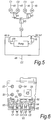
Figure 5 shows a schematic air flow logic diagram of the assembly of the invention; and -
Figure 6 shows a schematic view of the interior of the control unit of the assembly ofFigure 1 showing the air manifold. - In
Figure 1 a control unit assembly and compression device according to an embodiment of the invention is shown worn on the leg of a patient. The device comprises asleeve 2 having aleg cuff 4 connected to afoot cuff 6. The device also comprises acontrol unit assembly 8 comprising acontrol unit 10. Thecontrol unit 10 is small and when removed from thesleeve 2 may be hand held. Thecontrol unit 10 is battery powered and rechargeable so that it can be recharged when attached to or detached from thedevice 2.Figure 1 also shows thepouch 12 provided onsleeve 2 for receiving thecontrol unit 10 and the low profile of the assembly. The control unit assembly follows the contour of the device and integrates the assembly into the device. -
Figure 2 is a perspective view taken from above the device with the control unit removed showing the interior of thepouch 12 and thebacking plate 14. The control unit may be slidably engaged in the pouch and retained in position by a latching means.Figure 1 shows arelease button 22 positioned on the pouch of the device which when depressed releases the control unit from the pouch. -
Figure 3 is a perspective view of thecontrol unit 10 removed from the assembly and taken from below the unit, showing theconnectors 16 for engagement with the rigid connectors of the backing plate. -
Figure 4 is a perspective view of thebacking plate 14, removed from the device for the purposes of illustration, showing therigid connectors 18 for engagement with theconnectors 16 of the control unit.Figure 4 shows thecontrol unit 10 being slid into engagement with thebacking plate 14. As thecontrol unit 10 is slid into the backing plate, it begins to compress twosprings 20 which act to bias thecontrol unit 10 andbacking plate 14 apart. Further sliding movement of thecontrol unit 10 causes theconnectors control unit 10 in thepouch 12 against thesprings 20. Thecontrol unit 10 is released from thepouch 12 by depressing button 22 (Figure 1 ), the outline of which is visible on thesleeve 2. Thesprings 20 then cause the assembly to spring apart and thecontrol unit 10 can be removed from the device. Thesprings 20 can be in the form of a leaf spring located in the backing plate which similarly biases the parts of the assembly apart. -
Figure 4 also shows air filter 24 provided on the air inlet/outlet connector of thebacking plate 14. As the filter is provided on thebacking plate 14, it is naturally replaced when the control unit is used with a new device. This reduces the service requirements of the control unit. - Referring to
Figures 5 and 6 , thecontrol unit 10 hasfluid flow conduits conduit 48 by the operation of pump and valves V4 and V5 under instruction from a processor (not shown). The processor instructs valves V3, V1 and V2 which are arranged between the air inlet C5 and theconduits Figure 5 it can be seen that valve V3 directs fluid from/to the air inlet/outlet C5 to/from either valve V1 or V2 which in turn selectively open or close fluid paths to connectors C1 or C2, or C3 or C4. The valves are preferably latching valves. - A sensor S1 (
Figure 6 ) is located inconduit 40 between connector C1 and valve V1 in thecontrol unit 10. Similarly, sensors S2, S3 and S4 are located inconduits -
Figure 6 also shows theair manifold 50 with its labyrinth of passages that supplies air from the pump to each of the connectors C1 to C5. Theair manifold 50 replaces the external tubes needed with prior art devices between a distal control unit and the connectors of the device.
Claims (12)
- A control unit assembly for a medical device wherein the assembly comprises a control unit (10) and a docking unit, the docking unit located on the medical device, the medical device comprising a compression device for a limb, the compression device comprising a sleeve (2) with inflatable cells ; the control unit (10) comprising
a pump,
at least two conduits and
control means for controlling the flow of fluid from the pump through the conduits, characterised in that:the docking unit comprises a backing plate (14) which carries rigid fluid transfer connectors (18) which detachably connect the conduits to inflatable cells of the device;the conduits each comprise a rigid internal passage located in the control unit (10) which terminates in a connector (16) configured to make a detachable connection between the control unit and the docking unit so that the control unit can be readily attached and detached from the device;each connector (16) of the control unit (10) able to engage the fluid transfer connector (18) of the docking unit to form a fluid tight seal andthe control unit (10) slides into connection with the backing plate (14) to form the fluid tight seal. - The control unit assembly according to claim 1 wherein a valve is located between the pump and each conduit.
- The control unit assembly according to claims 1 or 2 wherein the rigid conduits form an air manifold in the control unit.
- The control unit assembly according to any preceding claim wherein the control unit further comprises a plurality of valves located between the pump and the conduits, the plurality of valves being arranged in a ranked structure.
- The control unit assembly according to claim 4 wherein the ranked valve structure comprises a first rank latching valve connected to an external fluid source via the pump which valve when latched open in a first position allows fluid to flow to a second rank latching valve, which directs fluid flow between two conduits, said first rank latching valve when latched open in a second position allows fluid to flow to a further second rank latching valve which directs fluid flow between a further two conduits.
- The control unit assembly according to claim 5, wherein each of the latching valves is located in the manifold of the control unit.
- The control unit assembly according to any one of claims 5 to 6, wherein the opening of a second rank valve in the valve structure permits the transfer of fluid between a first inflatable cell and a second inflatable cell in the device.
- The control unit assembly according to claim 4 or 5 wherein a pressure sensor is located between each conduit and its latching valve.
- The control unit assembly according to any preceding claim, wherein the device is adapted for use below the knee of a patient and comprises three inflatable cells located in the region between the knee and the ankle and two inflatable cells located in the heel and foot region.
- The control unit assembly according to claim 1 wherein the control unit, when assembled with the docking unit, is integrated into the outer contour of the device.
- A control unit assembly for a medical device as claimed in claim 1 wherein the docking unit comprises an air inlet connector which detachably connects to a connector (16) of the control unit and which provides air to the pump, the air inlet connector being provided with a filter.
- A control unit assembly as claimed in any preceding claim wherein the control unit assembly is positioned on or within an outer sleeve of the compression device.
Applications Claiming Priority (2)
| Application Number | Priority Date | Filing Date | Title |
|---|---|---|---|
| GBGB0601451.8A GB0601451D0 (en) | 2006-01-24 | 2006-01-24 | Control unit assembly |
| PCT/GB2007/000244 WO2007085828A1 (en) | 2006-01-24 | 2007-01-24 | Control unit assembly |
Publications (2)
| Publication Number | Publication Date |
|---|---|
| EP1983963A1 EP1983963A1 (en) | 2008-10-29 |
| EP1983963B1 true EP1983963B1 (en) | 2019-09-25 |
Family
ID=36060797
Family Applications (1)
| Application Number | Title | Priority Date | Filing Date |
|---|---|---|---|
| EP07705019.3A Active EP1983963B1 (en) | 2006-01-24 | 2007-01-24 | Control unit assembly |
Country Status (10)
| Country | Link |
|---|---|
| US (1) | US11471116B2 (en) |
| EP (1) | EP1983963B1 (en) |
| JP (1) | JP5015961B2 (en) |
| CN (1) | CN101370461A (en) |
| AU (1) | AU2007209121A1 (en) |
| CA (1) | CA2635115C (en) |
| GB (1) | GB0601451D0 (en) |
| NZ (1) | NZ569182A (en) |
| TW (1) | TWI413518B (en) |
| WO (1) | WO2007085828A1 (en) |
Families Citing this family (24)
| Publication number | Priority date | Publication date | Assignee | Title |
|---|---|---|---|---|
| US8535253B2 (en) | 2008-09-30 | 2013-09-17 | Covidien Lp | Tubeless compression device |
| US8177734B2 (en) | 2008-09-30 | 2012-05-15 | Tyco Healthcare Group Lp | Portable controller unit for a compression device |
| US8394043B2 (en) | 2010-02-12 | 2013-03-12 | Covidien Lp | Compression garment assembly |
| TWI621420B (en) | 2010-04-08 | 2018-04-21 | 病童醫院 | Use of remote ischemic conditioning for traumatic injury |
| US8844075B2 (en) * | 2010-10-22 | 2014-09-30 | Hill-Rom Services, Inc. | Footboard with partial mattress integration |
| US8764789B2 (en) | 2011-04-15 | 2014-07-01 | CellAegis Devices Inc. | System for performing remote ischemic conditioning |
| CA2904162A1 (en) | 2013-03-15 | 2014-12-18 | The Hospital For Sick Children | Methods relating to the use of remote ischemic conditioning |
| WO2014140832A2 (en) | 2013-03-15 | 2014-09-18 | The Hospital For Sick Children | Treatment of erectile dysfunction using remote ischemic conditioning |
| AU2013203746B2 (en) | 2013-03-15 | 2015-05-07 | Cellaegis Devices, Inc. | Gas Powered System for Performing Remote Ischemic Conditioning |
| CA2942614A1 (en) | 2013-03-15 | 2014-10-16 | The Hospital For Sick Children | Methods for modulating autophagy using remote ischemic conditioning |
| US20150057585A1 (en) * | 2013-08-20 | 2015-02-26 | Covidien Lp | Compression device having compliance tracking |
| US20150094629A1 (en) * | 2013-09-27 | 2015-04-02 | Covidien Lp | Compression garment controlling |
| USD870297S1 (en) | 2017-09-28 | 2019-12-17 | Tactile Systems Technology, Inc. | Trunk garment |
| JP2021502152A (en) | 2017-11-06 | 2021-01-28 | タクティル システムズ テクノロジー,インコーポレイティド | Compression garment system |
| CN111601545B (en) | 2017-11-09 | 2024-05-07 | 康沃特克科技公司 | Ostomy monitoring systems and methods |
| USD893514S1 (en) | 2018-11-08 | 2020-08-18 | 11 Health And Technologies Limited | Display screen or portion thereof with graphical user interface |
| US20210137784A1 (en) * | 2019-01-11 | 2021-05-13 | Li Zhijian | Massage Apparatus |
| DE102019201591B4 (en) * | 2019-02-07 | 2025-05-28 | Bühler Motor GmbH | Airplane seat massage system and airplane seat with a massage system |
| KR102179175B1 (en) * | 2019-03-11 | 2020-11-16 | (주)선메딕스 | Movable air massage apparatus |
| CA3198681A1 (en) | 2020-10-15 | 2022-04-21 | Convatec Technologies Inc. | Ostomy systems and methods |
| WO2022155536A2 (en) * | 2021-01-15 | 2022-07-21 | Inova Labs, Inc. Dba Monterey Health | Systems for circulatory-related disorders |
| CN112716764A (en) * | 2021-01-20 | 2021-04-30 | 湖南省肿瘤医院 | Lymphedema limb end pressure treatment device |
| CN116847750A (en) * | 2021-01-29 | 2023-10-03 | 泰乐博迪股份有限公司 | Pneumatic compression unit with integrated pump |
| US11839244B1 (en) * | 2023-07-11 | 2023-12-12 | Jeffery B. Jorden | Leg massaging trouser assembly |
Citations (3)
| Publication number | Priority date | Publication date | Assignee | Title |
|---|---|---|---|---|
| JPH0614722Y2 (en) * | 1988-12-15 | 1994-04-20 | 松下電工株式会社 | Electronic blood pressure monitor |
| JP2669858B2 (en) * | 1988-07-26 | 1997-10-29 | 松下電工株式会社 | Wrist sphygmomanometer |
| US5687732A (en) * | 1994-10-07 | 1997-11-18 | Omron Corporation | Blood pressure monitor |
Family Cites Families (68)
| Publication number | Priority date | Publication date | Assignee | Title |
|---|---|---|---|---|
| US5022387A (en) | 1987-09-08 | 1991-06-11 | The Kendall Company | Antiembolism stocking used in combination with an intermittent pneumatic compression device |
| US4858596A (en) | 1988-02-18 | 1989-08-22 | The Kendall Company | Portable sequential compression device |
| US5117812A (en) | 1990-11-05 | 1992-06-02 | The Kendall Company | Segmented compression device for the limb |
| US5263473A (en) | 1990-11-05 | 1993-11-23 | The Kendall Company | Compression device for the limb |
| US5383894A (en) | 1993-07-30 | 1995-01-24 | The Kendall Co. | Compression device having stepper motor controlled valves |
| US5795312A (en) | 1993-09-27 | 1998-08-18 | The Kendall Company | Compression sleeve |
| US6786879B1 (en) | 1994-04-05 | 2004-09-07 | Kci Licensing, Inc. | Gradient sequential compression system for preventing deep vein thrombosis |
| US5575762A (en) | 1994-04-05 | 1996-11-19 | Beiersdorf-Jobst, Inc. | Gradient sequential compression system and method for reducing the occurrence of deep vein thrombosis |
| CA2153375C (en) | 1994-07-26 | 2000-09-12 | Arnold Tobler | Attachment of hook and loop fastener to a compression sleeve |
| US5876359A (en) | 1994-11-14 | 1999-03-02 | Bock; Malcolm G. | Sequential compression device controller |
| US5843007A (en) | 1996-04-29 | 1998-12-01 | Mcewen; James Allen | Apparatus and method for periodically applying a pressure waveform to a limb |
| JPH119633A (en) * | 1997-06-27 | 1999-01-19 | Tec Corp | Fluid massaging device |
| JPH1119145A (en) | 1997-07-01 | 1999-01-26 | Nitto Kohki Co Ltd | Compressed air distribution valve and distribution device |
| US6123681A (en) | 1998-03-31 | 2000-09-26 | Global Vascular Concepts, Inc. | Anti-embolism stocking device |
| US6041243A (en) | 1998-05-15 | 2000-03-21 | Northrop Grumman Corporation | Personal communications unit |
| US6007559A (en) | 1998-06-12 | 1999-12-28 | Aci Medical | Vascular assist methods and apparatus |
| US6544202B2 (en) | 1998-08-12 | 2003-04-08 | Mcewen James Allen | Apparatus and method for applying an adaptable pressure waveform to a limb |
| US6062244A (en) | 1998-08-13 | 2000-05-16 | Aci Medical | Fluidic connector |
| US6231532B1 (en) | 1998-10-05 | 2001-05-15 | Tyco International (Us) Inc. | Method to augment blood circulation in a limb |
| JP3909789B2 (en) | 1998-12-28 | 2007-04-25 | 日東工器株式会社 | Air massager |
| US6206510B1 (en) | 1999-04-22 | 2001-03-27 | Hewlett-Packard Company | Method and apparatus for adapting an ink jet printing system for receiving an alternate supply of ink |
| US6290662B1 (en) | 1999-05-28 | 2001-09-18 | John K. Morris | Portable, self-contained apparatus for deep vein thrombosis (DVT) prophylaxis |
| US6198204B1 (en) | 2000-01-27 | 2001-03-06 | Michael D. Pottenger | Piezoelectrically controlled active wear |
| WO2002055005A1 (en) * | 2001-01-12 | 2002-07-18 | Midtown Technology Ltd. | Inflatable massage garment |
| US7001384B2 (en) | 2000-06-07 | 2006-02-21 | Aircast Llc | Method and apparatus for facilitating the healing of bone fractures |
| US6463934B1 (en) | 2000-06-12 | 2002-10-15 | Aircast, Inc. | Method for providing enhanced blood circulation |
| US6846295B1 (en) | 2000-11-20 | 2005-01-25 | Mego Afek Industrial Measuring Instruments | Compression sleeve |
| US6558338B1 (en) | 2000-11-20 | 2003-05-06 | Mego Afek Industrial Measuring Instruments | System for and method of applying pressure to human body |
| US6620116B2 (en) | 2000-12-08 | 2003-09-16 | Michael P. Lewis | External counterpulsation unit |
| US6632188B2 (en) | 2001-01-08 | 2003-10-14 | D2Rm Corp. | Foot massaging apparatus utilizing air inflated nodes and air inflated nodes combined with a fluid |
| IL141824A (en) | 2001-03-05 | 2008-11-03 | Flowmedic Ltd | Portable device for the enhancement of the circulation and for the prevention of stasis related deep vein thrombosis (dvt) |
| JP3899369B2 (en) * | 2001-05-16 | 2007-03-28 | 株式会社フジ医療器 | Massage machine |
| JP2003062023A (en) * | 2001-08-22 | 2003-03-04 | Noritz Corp | Device for massaging lower limb |
| WO2003053323A2 (en) | 2001-12-11 | 2003-07-03 | Noclots Limited | Improvements in and relating to calf compression devices |
| SG103371A1 (en) | 2001-12-28 | 2004-04-29 | Matsushita Electric Works Ltd | Wearable human motion applicator |
| IL160185A0 (en) | 2004-02-02 | 2004-07-25 | Flowmedic Israel Ltd | A portable device for the enhancement of circulation of blood and lymph flow in a limb |
| US6749556B2 (en) | 2002-05-10 | 2004-06-15 | Scimed Life Systems, Inc. | Electroactive polymer based artificial sphincters and artificial muscle patches |
| GB0217996D0 (en) | 2002-08-02 | 2002-09-11 | Novamedix Distrib Ltd | An inflatable device for use in impulse therapy |
| ATE398988T1 (en) | 2003-02-24 | 2008-07-15 | Danfoss As | ELECTROACTIVE ELASTIC COMPRESSION BANDAGE |
| GB0307097D0 (en) | 2003-03-27 | 2003-04-30 | Bristol Myers Squibb Co | Compression device for the limb |
| WO2004091463A2 (en) * | 2003-04-11 | 2004-10-28 | Hill-Rom Services, Inc. | System for compression therapy |
| US7491185B2 (en) | 2003-08-21 | 2009-02-17 | Boston Scientific Scimed, Inc. | External counterpulsation device using electroactive polymer actuators |
| IL164286A0 (en) | 2004-09-26 | 2005-12-18 | Benny Rousso | A portable device for the enhancement of blood circulation |
| WO2005120500A2 (en) | 2003-09-03 | 2005-12-22 | Flowmedic Limited | Sleeves for accommodating a circulation enhancement device |
| US7637879B2 (en) | 2003-12-29 | 2009-12-29 | Medical Compression Systems, (Dbn) Ltd. | Method and apparatus for assisting vascular flow through external compression synchronized with venous phasic flow |
| US7871387B2 (en) | 2004-02-23 | 2011-01-18 | Tyco Healthcare Group Lp | Compression sleeve convertible in length |
| US7354410B2 (en) | 2004-02-23 | 2008-04-08 | Tyco Healthcare Group Lp | Compression treatment system |
| TWM253369U (en) | 2004-03-04 | 2004-12-21 | Chia Jei Technology Business C | Miniature self-administrative-type device for prevention of vein thrombosis |
| US8079969B2 (en) | 2004-06-09 | 2011-12-20 | Benny Rousso | Portable self-contained device for enhancing circulation |
| IL164285A0 (en) | 2004-09-26 | 2005-12-18 | Benny Rousso | A portable device for the enhancent of blood |
| IL164360A0 (en) | 2004-09-29 | 2005-12-18 | Benny Rousso | A device for providing intermittent compression toa limb |
| CN101094641B (en) | 2005-01-04 | 2011-05-18 | 史蒂夫·卡克纳 | Automatic massage therapy equipment for biomechanical restorative massage |
| JP2006305293A (en) | 2005-03-31 | 2006-11-09 | Nitto Kohki Co Ltd | Pneumatic body action device |
| US8235921B2 (en) | 2005-05-01 | 2012-08-07 | Flow Medic Limited | Computerized portable device for the enhancement of circulation |
| US20060287672A1 (en) | 2005-06-15 | 2006-12-21 | Western Clinical Engineering Ltd. | Tourniquet cuff with improved pneumatic passageway |
| US7442175B2 (en) | 2005-12-12 | 2008-10-28 | Tyco Healthcare Group Lp | Compression sleeve having air conduit |
| US8029451B2 (en) | 2005-12-12 | 2011-10-04 | Tyco Healthcare Group Lp | Compression sleeve having air conduits |
| US7618384B2 (en) | 2006-09-20 | 2009-11-17 | Tyco Healthcare Group Lp | Compression device, system and method of use |
| GB0622415D0 (en) | 2006-11-10 | 2006-12-20 | Huntleigh Technology Plc | Compression system |
| EP2162090A1 (en) | 2007-07-04 | 2010-03-17 | Nanopowers S.A. | Artificial contractile structure and apparatus comprising such structure |
| US8387266B2 (en) | 2008-12-02 | 2013-03-05 | Medical Minds LLC | Device for measuring a body part of a living being |
| US7992217B2 (en) | 2009-04-30 | 2011-08-09 | The Invention Science Fund I, Llc | Shape changing material |
| US8162869B2 (en) | 2009-07-10 | 2012-04-24 | Tyco Healthcare Group Lp | Hybrid compression garmet |
| US20110040221A1 (en) | 2009-08-17 | 2011-02-17 | Kci Licensing, Inc. | System and Method to Reduce Stasis-Induced Reperfusion Injury |
| US8403870B2 (en) | 2009-09-15 | 2013-03-26 | Covidien Lp | Portable, self-contained compression device |
| US8523794B2 (en) | 2009-09-17 | 2013-09-03 | Milka Llc | Method and apparatus for treating lymphedema |
| US20110131839A1 (en) | 2009-12-03 | 2011-06-09 | C-Boot Ltd. | Pneumatic Alternating Pressure Relief of a Foot |
| US11000444B2 (en) | 2010-02-08 | 2021-05-11 | Gnotrix, Llc | Treatment devices and methods |
-
2006
- 2006-01-24 GB GBGB0601451.8A patent/GB0601451D0/en not_active Ceased
-
2007
- 2007-01-23 TW TW096102599A patent/TWI413518B/en not_active IP Right Cessation
- 2007-01-24 WO PCT/GB2007/000244 patent/WO2007085828A1/en not_active Ceased
- 2007-01-24 EP EP07705019.3A patent/EP1983963B1/en active Active
- 2007-01-24 AU AU2007209121A patent/AU2007209121A1/en not_active Abandoned
- 2007-01-24 NZ NZ569182A patent/NZ569182A/en not_active IP Right Cessation
- 2007-01-24 CA CA2635115A patent/CA2635115C/en active Active
- 2007-01-24 CN CNA2007800027322A patent/CN101370461A/en active Pending
- 2007-01-24 JP JP2008551869A patent/JP5015961B2/en not_active Expired - Fee Related
-
2017
- 2017-12-21 US US15/850,257 patent/US11471116B2/en active Active
Patent Citations (3)
| Publication number | Priority date | Publication date | Assignee | Title |
|---|---|---|---|---|
| JP2669858B2 (en) * | 1988-07-26 | 1997-10-29 | 松下電工株式会社 | Wrist sphygmomanometer |
| JPH0614722Y2 (en) * | 1988-12-15 | 1994-04-20 | 松下電工株式会社 | Electronic blood pressure monitor |
| US5687732A (en) * | 1994-10-07 | 1997-11-18 | Omron Corporation | Blood pressure monitor |
Also Published As
| Publication number | Publication date |
|---|---|
| US11471116B2 (en) | 2022-10-18 |
| JP5015961B2 (en) | 2012-09-05 |
| CN103784305A (en) | 2014-05-14 |
| JP2009523590A (en) | 2009-06-25 |
| WO2007085828A1 (en) | 2007-08-02 |
| AU2007209121A1 (en) | 2007-08-02 |
| EP1983963A1 (en) | 2008-10-29 |
| GB0601451D0 (en) | 2006-03-08 |
| CA2635115A1 (en) | 2007-08-02 |
| TW200800136A (en) | 2008-01-01 |
| CA2635115C (en) | 2014-09-23 |
| US20190290220A9 (en) | 2019-09-26 |
| CN101370461A (en) | 2009-02-18 |
| TWI413518B (en) | 2013-11-01 |
| NZ569182A (en) | 2011-05-27 |
| US20180110479A1 (en) | 2018-04-26 |
Similar Documents
| Publication | Publication Date | Title |
|---|---|---|
| CA2635115C (en) | Control unit assembly | |
| US10092250B2 (en) | Control unit for a medical device | |
| US11826302B2 (en) | Wearable robotic device | |
| US6494852B1 (en) | Portable ambulant pneumatic compression system | |
| US10391211B2 (en) | Negative pressure wound therapy orthopedic device | |
| KR20160046865A (en) | Compression garment controller | |
| US20230054745A1 (en) | Unified pneumatic and electrical connector system and method | |
| MX2008009132A (en) | Control unit assembly | |
| CN103784305B (en) | Medical treatment device | |
| CN121287461A (en) | Wearable devices |
Legal Events
| Date | Code | Title | Description |
|---|---|---|---|
| PUAI | Public reference made under article 153(3) epc to a published international application that has entered the european phase |
Free format text: ORIGINAL CODE: 0009012 |
|
| 17P | Request for examination filed |
Effective date: 20080821 |
|
| AK | Designated contracting states |
Kind code of ref document: A1 Designated state(s): AT BE BG CH CY CZ DE DK EE ES FI FR GB GR HU IE IS IT LI LT LU LV MC NL PL PT RO SE SI SK TR |
|
| RIN1 | Information on inventor provided before grant (corrected) |
Inventor name: TUCKER, CARL, ESCORT Inventor name: WILSON, GRAHAM, PETER Inventor name: BAKER, TROY, A. Inventor name: BERGENS, THOMAS Inventor name: LOOF, STEFAN Inventor name: LINNANE, PATRICK, GERRARD Inventor name: BONNEFIN, WAYNE, LEE Inventor name: TABRON, IAN, STEWART |
|
| RAP1 | Party data changed (applicant data changed or rights of an application transferred) |
Owner name: CONVATEC TECHNOLOGIES INC. |
|
| DAX | Request for extension of the european patent (deleted) | ||
| RAP1 | Party data changed (applicant data changed or rights of an application transferred) |
Owner name: SWELLING SOLUTIONS, INC. |
|
| 17Q | First examination report despatched |
Effective date: 20150527 |
|
| STAA | Information on the status of an ep patent application or granted ep patent |
Free format text: STATUS: EXAMINATION IS IN PROGRESS |
|
| GRAP | Despatch of communication of intention to grant a patent |
Free format text: ORIGINAL CODE: EPIDOSNIGR1 |
|
| STAA | Information on the status of an ep patent application or granted ep patent |
Free format text: STATUS: GRANT OF PATENT IS INTENDED |
|
| INTG | Intention to grant announced |
Effective date: 20181217 |
|
| GRAJ | Information related to disapproval of communication of intention to grant by the applicant or resumption of examination proceedings by the epo deleted |
Free format text: ORIGINAL CODE: EPIDOSDIGR1 |
|
| STAA | Information on the status of an ep patent application or granted ep patent |
Free format text: STATUS: EXAMINATION IS IN PROGRESS |
|
| GRAP | Despatch of communication of intention to grant a patent |
Free format text: ORIGINAL CODE: EPIDOSNIGR1 |
|
| STAA | Information on the status of an ep patent application or granted ep patent |
Free format text: STATUS: GRANT OF PATENT IS INTENDED |
|
| INTC | Intention to grant announced (deleted) | ||
| INTG | Intention to grant announced |
Effective date: 20190402 |
|
| GRAS | Grant fee paid |
Free format text: ORIGINAL CODE: EPIDOSNIGR3 |
|
| GRAA | (expected) grant |
Free format text: ORIGINAL CODE: 0009210 |
|
| STAA | Information on the status of an ep patent application or granted ep patent |
Free format text: STATUS: THE PATENT HAS BEEN GRANTED |
|
| AK | Designated contracting states |
Kind code of ref document: B1 Designated state(s): AT BE BG CH CY CZ DE DK EE ES FI FR GB GR HU IE IS IT LI LT LU LV MC NL PL PT RO SE SI SK TR |
|
| REG | Reference to a national code |
Ref country code: GB Ref legal event code: FG4D |
|
| REG | Reference to a national code |
Ref country code: CH Ref legal event code: EP |
|
| REG | Reference to a national code |
Ref country code: AT Ref legal event code: REF Ref document number: 1183102 Country of ref document: AT Kind code of ref document: T Effective date: 20191015 |
|
| REG | Reference to a national code |
Ref country code: IE Ref legal event code: FG4D |
|
| REG | Reference to a national code |
Ref country code: DE Ref legal event code: R096 Ref document number: 602007059257 Country of ref document: DE |
|
| REG | Reference to a national code |
Ref country code: NL Ref legal event code: MP Effective date: 20190925 |
|
| PG25 | Lapsed in a contracting state [announced via postgrant information from national office to epo] |
Ref country code: LT Free format text: LAPSE BECAUSE OF FAILURE TO SUBMIT A TRANSLATION OF THE DESCRIPTION OR TO PAY THE FEE WITHIN THE PRESCRIBED TIME-LIMIT Effective date: 20190925 Ref country code: BG Free format text: LAPSE BECAUSE OF FAILURE TO SUBMIT A TRANSLATION OF THE DESCRIPTION OR TO PAY THE FEE WITHIN THE PRESCRIBED TIME-LIMIT Effective date: 20191225 Ref country code: FI Free format text: LAPSE BECAUSE OF FAILURE TO SUBMIT A TRANSLATION OF THE DESCRIPTION OR TO PAY THE FEE WITHIN THE PRESCRIBED TIME-LIMIT Effective date: 20190925 Ref country code: SE Free format text: LAPSE BECAUSE OF FAILURE TO SUBMIT A TRANSLATION OF THE DESCRIPTION OR TO PAY THE FEE WITHIN THE PRESCRIBED TIME-LIMIT Effective date: 20190925 |
|
| REG | Reference to a national code |
Ref country code: LT Ref legal event code: MG4D |
|
| PG25 | Lapsed in a contracting state [announced via postgrant information from national office to epo] |
Ref country code: GR Free format text: LAPSE BECAUSE OF FAILURE TO SUBMIT A TRANSLATION OF THE DESCRIPTION OR TO PAY THE FEE WITHIN THE PRESCRIBED TIME-LIMIT Effective date: 20191226 Ref country code: LV Free format text: LAPSE BECAUSE OF FAILURE TO SUBMIT A TRANSLATION OF THE DESCRIPTION OR TO PAY THE FEE WITHIN THE PRESCRIBED TIME-LIMIT Effective date: 20190925 |
|
| REG | Reference to a national code |
Ref country code: AT Ref legal event code: MK05 Ref document number: 1183102 Country of ref document: AT Kind code of ref document: T Effective date: 20190925 |
|
| PG25 | Lapsed in a contracting state [announced via postgrant information from national office to epo] |
Ref country code: NL Free format text: LAPSE BECAUSE OF FAILURE TO SUBMIT A TRANSLATION OF THE DESCRIPTION OR TO PAY THE FEE WITHIN THE PRESCRIBED TIME-LIMIT Effective date: 20190925 Ref country code: AT Free format text: LAPSE BECAUSE OF FAILURE TO SUBMIT A TRANSLATION OF THE DESCRIPTION OR TO PAY THE FEE WITHIN THE PRESCRIBED TIME-LIMIT Effective date: 20190925 Ref country code: EE Free format text: LAPSE BECAUSE OF FAILURE TO SUBMIT A TRANSLATION OF THE DESCRIPTION OR TO PAY THE FEE WITHIN THE PRESCRIBED TIME-LIMIT Effective date: 20190925 Ref country code: RO Free format text: LAPSE BECAUSE OF FAILURE TO SUBMIT A TRANSLATION OF THE DESCRIPTION OR TO PAY THE FEE WITHIN THE PRESCRIBED TIME-LIMIT Effective date: 20190925 Ref country code: ES Free format text: LAPSE BECAUSE OF FAILURE TO SUBMIT A TRANSLATION OF THE DESCRIPTION OR TO PAY THE FEE WITHIN THE PRESCRIBED TIME-LIMIT Effective date: 20190925 Ref country code: PL Free format text: LAPSE BECAUSE OF FAILURE TO SUBMIT A TRANSLATION OF THE DESCRIPTION OR TO PAY THE FEE WITHIN THE PRESCRIBED TIME-LIMIT Effective date: 20190925 Ref country code: PT Free format text: LAPSE BECAUSE OF FAILURE TO SUBMIT A TRANSLATION OF THE DESCRIPTION OR TO PAY THE FEE WITHIN THE PRESCRIBED TIME-LIMIT Effective date: 20200127 |
|
| PG25 | Lapsed in a contracting state [announced via postgrant information from national office to epo] |
Ref country code: SK Free format text: LAPSE BECAUSE OF FAILURE TO SUBMIT A TRANSLATION OF THE DESCRIPTION OR TO PAY THE FEE WITHIN THE PRESCRIBED TIME-LIMIT Effective date: 20190925 Ref country code: IS Free format text: LAPSE BECAUSE OF FAILURE TO SUBMIT A TRANSLATION OF THE DESCRIPTION OR TO PAY THE FEE WITHIN THE PRESCRIBED TIME-LIMIT Effective date: 20200224 Ref country code: CZ Free format text: LAPSE BECAUSE OF FAILURE TO SUBMIT A TRANSLATION OF THE DESCRIPTION OR TO PAY THE FEE WITHIN THE PRESCRIBED TIME-LIMIT Effective date: 20190925 |
|
| REG | Reference to a national code |
Ref country code: DE Ref legal event code: R097 Ref document number: 602007059257 Country of ref document: DE |
|
| PG2D | Information on lapse in contracting state deleted |
Ref country code: IS |
|
| PG25 | Lapsed in a contracting state [announced via postgrant information from national office to epo] |
Ref country code: DK Free format text: LAPSE BECAUSE OF FAILURE TO SUBMIT A TRANSLATION OF THE DESCRIPTION OR TO PAY THE FEE WITHIN THE PRESCRIBED TIME-LIMIT Effective date: 20190925 Ref country code: IS Free format text: LAPSE BECAUSE OF FAILURE TO SUBMIT A TRANSLATION OF THE DESCRIPTION OR TO PAY THE FEE WITHIN THE PRESCRIBED TIME-LIMIT Effective date: 20200126 |
|
| PLBE | No opposition filed within time limit |
Free format text: ORIGINAL CODE: 0009261 |
|
| STAA | Information on the status of an ep patent application or granted ep patent |
Free format text: STATUS: NO OPPOSITION FILED WITHIN TIME LIMIT |
|
| PG25 | Lapsed in a contracting state [announced via postgrant information from national office to epo] |
Ref country code: MC Free format text: LAPSE BECAUSE OF FAILURE TO SUBMIT A TRANSLATION OF THE DESCRIPTION OR TO PAY THE FEE WITHIN THE PRESCRIBED TIME-LIMIT Effective date: 20190925 |
|
| REG | Reference to a national code |
Ref country code: CH Ref legal event code: PL |
|
| 26N | No opposition filed |
Effective date: 20200626 |
|
| REG | Reference to a national code |
Ref country code: BE Ref legal event code: MM Effective date: 20200131 |
|
| REG | Reference to a national code |
Ref country code: DE Ref legal event code: R082 Ref document number: 602007059257 Country of ref document: DE Representative=s name: VENNER SHIPLEY GERMANY LLP, DE Ref country code: DE Ref legal event code: R082 Ref document number: 602007059257 Country of ref document: DE Representative=s name: VENNER SHIPLEY LLP, DE |
|
| PG25 | Lapsed in a contracting state [announced via postgrant information from national office to epo] |
Ref country code: LU Free format text: LAPSE BECAUSE OF NON-PAYMENT OF DUE FEES Effective date: 20200124 |
|
| PG25 | Lapsed in a contracting state [announced via postgrant information from national office to epo] |
Ref country code: SI Free format text: LAPSE BECAUSE OF FAILURE TO SUBMIT A TRANSLATION OF THE DESCRIPTION OR TO PAY THE FEE WITHIN THE PRESCRIBED TIME-LIMIT Effective date: 20190925 Ref country code: BE Free format text: LAPSE BECAUSE OF NON-PAYMENT OF DUE FEES Effective date: 20200131 Ref country code: LI Free format text: LAPSE BECAUSE OF NON-PAYMENT OF DUE FEES Effective date: 20200131 Ref country code: CH Free format text: LAPSE BECAUSE OF NON-PAYMENT OF DUE FEES Effective date: 20200131 |
|
| PGFP | Annual fee paid to national office [announced via postgrant information from national office to epo] |
Ref country code: IT Payment date: 20210122 Year of fee payment: 15 Ref country code: IE Payment date: 20210127 Year of fee payment: 15 |
|
| PG25 | Lapsed in a contracting state [announced via postgrant information from national office to epo] |
Ref country code: TR Free format text: LAPSE BECAUSE OF FAILURE TO SUBMIT A TRANSLATION OF THE DESCRIPTION OR TO PAY THE FEE WITHIN THE PRESCRIBED TIME-LIMIT Effective date: 20190925 Ref country code: CY Free format text: LAPSE BECAUSE OF FAILURE TO SUBMIT A TRANSLATION OF THE DESCRIPTION OR TO PAY THE FEE WITHIN THE PRESCRIBED TIME-LIMIT Effective date: 20190925 |
|
| PG25 | Lapsed in a contracting state [announced via postgrant information from national office to epo] |
Ref country code: IT Free format text: LAPSE BECAUSE OF NON-PAYMENT OF DUE FEES Effective date: 20220124 Ref country code: IE Free format text: LAPSE BECAUSE OF NON-PAYMENT OF DUE FEES Effective date: 20220124 |
|
| PGFP | Annual fee paid to national office [announced via postgrant information from national office to epo] |
Ref country code: GB Payment date: 20260127 Year of fee payment: 20 |
|
| PGFP | Annual fee paid to national office [announced via postgrant information from national office to epo] |
Ref country code: DE Payment date: 20260128 Year of fee payment: 20 |
|
| PGFP | Annual fee paid to national office [announced via postgrant information from national office to epo] |
Ref country code: FR Payment date: 20260126 Year of fee payment: 20 |