EP1983266A2 - Methods and systems to facilitate reducing combustor pressure drops - Google Patents
Methods and systems to facilitate reducing combustor pressure drops Download PDFInfo
- Publication number
- EP1983266A2 EP1983266A2 EP08154513A EP08154513A EP1983266A2 EP 1983266 A2 EP1983266 A2 EP 1983266A2 EP 08154513 A EP08154513 A EP 08154513A EP 08154513 A EP08154513 A EP 08154513A EP 1983266 A2 EP1983266 A2 EP 1983266A2
- Authority
- EP
- European Patent Office
- Prior art keywords
- streamline flow
- flow conditioner
- deflection plate
- combustor
- plate
- Prior art date
- Legal status (The legal status is an assumption and is not a legal conclusion. Google has not performed a legal analysis and makes no representation as to the accuracy of the status listed.)
- Withdrawn
Links
- 238000000034 method Methods 0.000 title description 13
- 230000007704 transition Effects 0.000 description 40
- MWUXSHHQAYIFBG-UHFFFAOYSA-N nitrogen oxide Inorganic materials O=[N] MWUXSHHQAYIFBG-UHFFFAOYSA-N 0.000 description 24
- 238000002485 combustion reaction Methods 0.000 description 23
- 239000000446 fuel Substances 0.000 description 14
- 239000007789 gas Substances 0.000 description 10
- 230000015572 biosynthetic process Effects 0.000 description 8
- 230000008878 coupling Effects 0.000 description 6
- 238000010168 coupling process Methods 0.000 description 6
- 238000005859 coupling reaction Methods 0.000 description 6
- 230000000694 effects Effects 0.000 description 5
- UGFAIRIUMAVXCW-UHFFFAOYSA-N Carbon monoxide Chemical compound [O+]#[C-] UGFAIRIUMAVXCW-UHFFFAOYSA-N 0.000 description 3
- 229910002091 carbon monoxide Inorganic materials 0.000 description 3
- 239000000567 combustion gas Substances 0.000 description 3
- 238000001816 cooling Methods 0.000 description 2
- VNWKTOKETHGBQD-UHFFFAOYSA-N methane Chemical compound C VNWKTOKETHGBQD-UHFFFAOYSA-N 0.000 description 2
- 230000005465 channeling Effects 0.000 description 1
- 238000013016 damping Methods 0.000 description 1
- 239000003344 environmental pollutant Substances 0.000 description 1
- 238000002309 gasification Methods 0.000 description 1
- 238000007689 inspection Methods 0.000 description 1
- 230000004048 modification Effects 0.000 description 1
- 238000012986 modification Methods 0.000 description 1
- 239000003345 natural gas Substances 0.000 description 1
- 230000010355 oscillation Effects 0.000 description 1
- 231100000719 pollutant Toxicity 0.000 description 1
- 238000010248 power generation Methods 0.000 description 1
Images


Classifications
-
- F—MECHANICAL ENGINEERING; LIGHTING; HEATING; WEAPONS; BLASTING
- F23—COMBUSTION APPARATUS; COMBUSTION PROCESSES
- F23R—GENERATING COMBUSTION PRODUCTS OF HIGH PRESSURE OR HIGH VELOCITY, e.g. GAS-TURBINE COMBUSTION CHAMBERS
- F23R3/00—Continuous combustion chambers using liquid or gaseous fuel
- F23R3/02—Continuous combustion chambers using liquid or gaseous fuel characterised by the air-flow or gas-flow configuration
- F23R3/04—Air inlet arrangements
- F23R3/06—Arrangement of apertures along the flame tube
- F23R3/08—Arrangement of apertures along the flame tube between annular flame tube sections, e.g. flame tubes with telescopic sections
-
- F—MECHANICAL ENGINEERING; LIGHTING; HEATING; WEAPONS; BLASTING
- F23—COMBUSTION APPARATUS; COMBUSTION PROCESSES
- F23R—GENERATING COMBUSTION PRODUCTS OF HIGH PRESSURE OR HIGH VELOCITY, e.g. GAS-TURBINE COMBUSTION CHAMBERS
- F23R3/00—Continuous combustion chambers using liquid or gaseous fuel
- F23R3/42—Continuous combustion chambers using liquid or gaseous fuel characterised by the arrangement or form of the flame tubes or combustion chambers
- F23R3/54—Reverse-flow combustion chambers
-
- Y—GENERAL TAGGING OF NEW TECHNOLOGICAL DEVELOPMENTS; GENERAL TAGGING OF CROSS-SECTIONAL TECHNOLOGIES SPANNING OVER SEVERAL SECTIONS OF THE IPC; TECHNICAL SUBJECTS COVERED BY FORMER USPC CROSS-REFERENCE ART COLLECTIONS [XRACs] AND DIGESTS
- Y10—TECHNICAL SUBJECTS COVERED BY FORMER USPC
- Y10T—TECHNICAL SUBJECTS COVERED BY FORMER US CLASSIFICATION
- Y10T29/00—Metal working
- Y10T29/49—Method of mechanical manufacture
- Y10T29/49316—Impeller making
- Y10T29/4932—Turbomachine making
Definitions
- This invention relates generally to combustors and more particularly, methods and systems to facilitate reducing pressure drops within gas turbine combustors and to facilitate increasing efficiency and lowering emissions and dampening thermo acoustic oscillations.
- At least some known gas turbine engines include a multi-stage compressor that compresses inlet air to higher pressures and temperatures.
- the compressed air is channeled to combustors which mix the compressed air and fuel to generate combustion gases directed towards a turbine.
- the turbine drives the compressor and/or other loads such as, but not limited to, electric generators and mechanical drive applications.
- Known combustors are generally formed with an outer case and a combustion liner coupled radially inward from the case.
- At least some known combustors also include a second liner, commonly referred to as a flow sleeve, which extends within the casing and around the combustion liner.
- Known flow sleeves include an inlet end that receives a portion of the compressed air channeled along a radially outer surface of the combustion liner.
- known flow sleeve configurations may also undesirably increase the pressure drop of air flowing through the flow sleeve.
- a method for assembling a gas turbine combustor for use with a turbine includes providing a combustor case having a first end, a second end, and a centerline extending there between.
- the method also includes coupling an end cover to the case first end and coupling a combustor liner within the case such that the liner is substantially coaxially aligned with respect to the case.
- the method also includes providing a streamline flow conditioner including a body that includes a radially outer surface and a radially inner surface, and a deflection plate that extends from the body.
- the deflection plate includes a radially outer surface and a radially inner surface that extends radially outward with respect to the centerline.
- the plate inner surface at least one of extends radially outward with respect to the centerline and defines a plurality of openings within the plate inner surface.
- the method further includes coupling the streamline flow conditioner to the case second end such that the streamline flow conditioner is coupled radially between the case and the combustor liner such that the deflection plate is adjacent the case second end.
- a gas turbine combustor system includes a case comprising a first end, a second end, and a centerline extending there between.
- the system also includes an end cover coupled to the case first end, a combustor liner coupled within the case such that the liner is substantially coaxially aligned with respect to the case, and a streamline flow conditioner coupled between the case and the combustor liner.
- the streamline flow conditioner including a body comprising a radially outer surface, a radially inner surface opposite the outer surface, a first end, and a second end. The body first end is adjacent the end cover. The body second end is adjacent the case second end.
- the system also includes a deflection plate including a radially outer surface and a radially inner surface opposing the plate outer surface.
- the deflection plate extends from the body second end.
- the plate inner surface at least one of extends radially outward with respect to the centerline and defines a plurality of openings within the plate inner surface.
- a streamline flow conditioner for a combustor includes a body including a radially outer surface, a radially inner surface opposite the outer surface, a first end, a second end, and a plurality of openings defined within the second end.
- the streamline flow conditioner also includes a deflection plate including a radially outer surface and a radially inner surface opposite the plate outer surface. The deflection plate extends from the body second end. The plate inner surface at least one of extends radially outward with respect to the centerline and defines a plurality of openings within the plate inner surface.
- exemplary streamline flow conditioners are described herein with respect to gas turbine systems, it should be appreciated that the exemplary streamline flow conditioners are applicable to other combustion systems such as, but not limited to, natural gas and integrated gasification combined-cycle (IGCC) power generation systems.
- IGCC natural gas and integrated gasification combined-cycle
- axial and axially are used throughout this application to refer to directions and orientations extending generally parallel to a centerline of the associated turbine engine.
- radial and radially are used throughout this application to refer to directions and orientations extending substantially perpendicular to a centerline of the turbine engine.
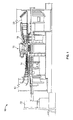
- FIG. 1 is a schematic illustration of an exemplary gas turbine system 10 including an intake section 12, a compressor section 14 coupled downstream from the intake section 12, a combustor section 16 coupled downstream from the intake section 12, a turbine section 18 coupled downstream from the combustor section 16, and an exhaust section 20.
- Turbine section 18 drives compressor section 14 and a load 22 such as, but not limited to, an electrical generator and a mechanical drive application.
- intake section 12 channels inlet air to compressor section 14.
- the inlet air is compressed to higher pressures and temperatures, and the compressed air is channeled to combustor section 16.
- Combustor section 16 facilitates mixing and burning the compressed air and fuel to generate combustion gases that are discharged towards turbine section 18 to drive compressor section 14 and/or load 22. Exhaust gases exiting turbine section 18 flow through exhaust section 20 to ambient atmosphere.
- FIG 2 is a cross-sectional view of a known combustor 24 that may be used with gas turbine system 10 (shown in Figure 1 ).
- combustor 24 includes a centerline axis A-A, an annular case 26, and end cover 28 coupled to a first end 30 of case 26.
- a plurality of fuel nozzles 32 and an additional fuel nozzle 34 are coupled to end cover 28.
- Combustor 24 also includes a combustion liner 36 and a streamline flow conditioner 38 that is coaxially coupled within case 26.
- streamline flow conditioner 38 is coupled to a second end 40 of case 26 and is coupled radially between case 26 and combustion liner 36. More specifically, streamline flow conditioner 38 is spaced a radial distance from combustion liner 36 such that an air passage 42 is defined there between.
- Streamline flow conditioner 38 includes a body 44 including a first end 46 and an opposite second end 48.
- a transition piece 50 is coupled to an end of combustion liner 36 near second end 48 to facilitate channeling combustion gases towards turbine nozzles (not shown).
- a combination of combustion liner 36, streamline flow conditioner second end 48, and/or transition piece 50 define a streamline flow conditioner inlet 52.
- a portion of compressed airflow 54 may enter passage 42 from a larger and/or higher pressure plenum (not shown) surrounding streamline flow conditioner inlet 52.
- pressure losses may develop near streamline flow conditioner inlet 52.
- other structural features near streamline flow conditioner inlet 52 may contribute to undesirable pressure losses in the compressed air flowing through passage 42.
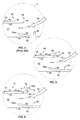
- Figure 3 is an enlarged cross-sectional view of a portion of streamline flow conditioner 38 of combustor 24 taken along area 3.
- transition piece 50 and streamline flow conditioner body second end 48 may contribute to, or cause, undesirable pressure losses in air flowing through combustor 24.
- transition piece 50 includes an annular bellmouth 56 and an annular support ring 58 that partially obstruct the compressed air entering passage 42 through streamline flow conditioner inlet 52 when transition piece is coupled to combustion liner 36.
- streamline flow conditioner body 44 includes a radially outer surface 60 and a radially inner surface 62 that are each substantially parallel to centerline axis A-A (shown in Figure 2 ).
- Second end 48 also includes a sharp edge 64 that extends substantially perpendicularly to centerline axis A-A.
- body edge 64 is axially spaced an axial distance X from an edge 56a of transition piece 50. Edge 64 partially obstructs compressed air entering passage 42 through streamline flow conditioner inlet 52 during operation.
- edge 64 is known to extend to a perforated inlet deflection plate (not shown) that extends radially inward from inner surface 62.
- edge 64 is known to create high pressure losses near streamline flow conditioner inlet 52.
- known combustors such as combustor 24 are configured to operate with a predetermined pressure drop in compressed air such as, but not limited to, an approximate 4.5 % pressure drop. As such, the remaining 3.5% pressure drop may be tolerated by other sections of combustor 24.
- the pressure losses resulting from edge 64 reduce the amount of air available for cooling combustion liner 36 and/or for mixing with fuel introduced by nozzles 32 coupled adjacent to first end 46 of streamline flow conditioner 38.
- FIG 4 is an enlarged cross-sectional view of an exemplary streamline flow conditioner 66 that may be used with combustor 24 (shown in Figure 2 ).
- Streamline flow conditioner 66 is substantially similar to streamline flow conditioner 38 shown in Figures 2 and 3 , and components in Figure 4 that are identical to components of Figures 2 and 3 , are identified in Figure 4 using the same reference numerals used in Figures 2 and 3 .
- streamline flow conditioner 66 includes a deflection plate 68 extending from second end edge 64.
- Deflection plate 68 includes an outer surface 70 that is oriented substantially parallel to a centerline axis A-A (shown in Figure 2 ) of combustor 24.
- Deflection plate 68 also includes an arcuate fillet 72 that is radially inward of, and opposes outer surface 70.
- Fillet 72 is formed with a radius of curvature R and extends radially outward from body inner surface 62 to deflection plate outer surface 70.
- fillet may include a non-circular cross-section.
- deflection plate 68 may be coupled to streamline flow conditioner body 44.
- deflection plate 68 may be formed with any shape such as, but not limited to, a curved shape that facilitates reducing a pressure drop at streamline flow conditioner inlet 52 as herein described.
- radius R may be any radius that facilitates reducing a pressure drop at streamline flow conditioner inlet 52 as herein described.
- deflection plate 68 provides a smoother transition for compressed airflow 54 directed into passage 42, as compared to known streamline flow conditioners. Because inner fillet 72 extends radially outward from inner surface 62, deflection plate 68 also provides a larger inlet opening, as compared to known streamline flow conditioners. As a result, streamline flow conditioner 66 facilitates reducing an amount of pressure drop adjacent streamline flow conditioner inlet 52 as compared to known streamline flow conditioners. As a result, an increased total pressure drop may be tolerated by other combustor components as compared to known combustors that include known streamline flow conditioners.
- deflection plate 68 also provides more airflow through streamline flow conditioner passage 42, as compared to known streamline flow conditioners. As a result, a larger amount of compressed air may be mixed with fuel for combustion, as compared to known streamline flow conditioners. As such, streamline flow conditioner 66 facilitates reducing the formation of air polluting emissions such as, but not limited to, CO and NO x . In addition, excess air towards the combustor headend may facilitate damping to combustor thermo acoustics.
- FIG 5 is an enlarged cross-sectional view of an exemplary streamline flow conditioner 74 that may be used with combustor 24 (shown in Figure 2 ).
- Streamline flow conditioner 74 is substantially similar to streamline flow conditioners 38 and 66 shown in Figures 2-4 respectively, and components in Figure 5 that are identical to components of Figures 2-4 , are identified in Figure 5 using the same reference numerals used in Figures 2-4 .
- streamline flow conditioner 74 includes a conical deflection plate 76 extending from second end edge 64.
- Deflection plate 76 includes an outer surface 78 that is oriented substantially parallel to a radially inner surface 80 opposing outer surface 78.
- Deflection plate 76 includes a free end edge 76a that connects outer surface 78 and inner surface 80.
- Deflection plate 76 is formed with a radius of curvature R and extends radially outward from body inner surface 62 to end edge 76a.
- deflection plate 76 may be coupled to streamline flow conditioner body 44. It should be appreciated that deflection plate 76 may be formed with any shape that facilitates reducing a pressure drop at streamline flow conditioner inlet 52 as herein described. Further, it should be appreciated that radius R may be any radius that facilitates reducing a pressure drop at streamline flow conditioner inlet 52 as herein described.
- deflection plate 76 provides a smoother transition for compressed airflow 54 directed into passage 42 as compared to known streamline flow conditioners. Because inner surface 80 extends radially outward from inner surface 62, deflection plate 76 also provides a larger inlet opening, as compared to known streamline flow conditioners. As a result, streamline flow conditioner 74 facilitates reducing an amount of pressure drop adjacent streamline flow conditioner inlet 52 as compared to known streamline flow conditioners. As a result, an increased total pressure drop may be tolerated by other combustor components, as compared to known combustors that include streamline flow conditioners.
- deflection plate 76 further provides more airflow through streamline flow conditioner passage 42, as compared to known streamline flow conditioners. As a result, a larger amount of compressed air may be mixed with fuel for combustion, as compared to known streamline flow conditioners. As such, streamline flow conditioner 74 facilitates reducing the formation of air polluting emissions such as, but not limited to, nitrogen oxides ("NO x ").
- NO x nitrogen oxides
- FIG 6 is an enlarged cross-sectional view of an exemplary streamline flow conditioner 82 that may be used with combustor 24 (shown in Figure 2 ).
- Streamline flow conditioner 82 is substantially similar to streamline flow conditioners 38, 66, and 74 shown in Figures 2-5 respectively, and components in Figure 6 that are identical to components of Figures 2-5 , are identified in Figure 6 using the same reference numerals used in Figures 2-5 .
- streamline flow conditioner 82 includes conical deflection plate 76 extending from second end edge 64.
- Deflection plate 76 includes outer surface 78 and radially inner surface 80.
- Streamline flow conditioner 82 also includes a plurality of openings 84 defined between outer and inner surfaces 60 and 62 of streamline flow conditioner body 44.
- deflection plate 76 provides a smoother transition for compressed airflow 54 directed into passage 42 as compared to known streamline flow conditioners. Because second end 48 includes openings 84, streamline flow conditioner 82 provides additional inlets of compressed airflow into passage 42, as compared to known streamline flow conditioners. Because inner surface 80 extends radially outward from inner surface 62, deflection plate 76 also provides a larger inlet opening, as compared to known streamline flow conditioners. As a result, streamline flow conditioner 82 facilitates reducing an amount of pressure drop adjacent streamline flow conditioner inlet 52 as compared to known streamline flow conditioners.
- deflection plate 76 further provides more airflow through streamline flow conditioner passage 42, as compared to known streamline flow conditioners.
- streamline flow conditioner 82 facilitates reducing the formation of air polluting emissions such as, but not limited to, NO x .
- FIG 7 is an enlarged cross-sectional view of an exemplary streamline flow conditioner 86 that may be used with combustor 24 (shown in Figure 2 ).
- Streamline flow conditioner 86 is substantially similar to streamline flow conditioners 38, 66, 74, and 82 shown in Figures 2-6 respectively, and components in Figure 7 that are identical to components of Figures 2-6 , are identified in Figure 7 using the same reference numerals used in Figures 2-6 .
- streamline flow conditioner 86 includes a deflection plate 88 extending from second end edge 64.
- Deflection plate 88 includes an outer surface 90, a radially inner surface 92 opposing outer surface 90, and an end portion 94 that connects outer surface 90 and inner surface 92.
- Inner surface 92 includes a radius of curvature R and extends radially outward from body inner surface 62 to end portion 94.
- End portion 94 has a substantially circular cross-section. In one embodiment, end portion may include a non-circular cross-section.
- deflection plate 88 may be coupled to streamline flow conditioner body 44.
- deflection plate 88 may be formed with any shape that facilitates reducing a pressure drop at streamline flow conditioner inlet 52 as herein described. Further, it should be appreciated that radius R may be any radius that facilitates reducing a pressure drop at streamline flow conditioner inlet 52 as herein described.
- deflection plate 88 provides a smoother transition for compressed airflow directed 54 into passage 42 as compared to known streamline flow conditioners. Because deflection plate 88 also includes end 94, deflection plate 88 provides a smoother transition for compressed airflow 54 directed into passage 42 as compared to known streamline flow conditioners. Because inner surface 92 extends radially outward from inner surface 62, deflection plate 88 also provides a larger inlet opening, as compared to known streamline flow conditioners. As a result, streamline flow conditioner 86 facilitates reducing an amount of pressure drop adjacent streamline flow conditioner inlet 52 as compared to known streamline flow conditioners.
- deflection plate 88 further provides more airflow through streamline flow conditioner passage 42, as compared to known streamline flow conditioners. As a result, a larger amount of compressed air may be mixed with fuel for combustion, as compared to known streamline flow conditioners.
- streamline flow conditioner 86 facilitates reducing the formation of air polluting emissions such as, but not limited to, NO x .
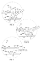
- FIG 8 is an enlarged cross-sectional view of an exemplary streamline flow conditioner 96 that may be used with combustor 24 (shown in Figure 2 ).
- Streamline flow conditioner 96 is substantially similar to streamline flow conditioners 38, 66, 74, 82, and 82 shown in Figures 2-7 respectively, and components in Figure 8 that are identical to components of Figures 2-7 , are identified in Figure 8 using the same reference numerals used in Figures 2-7 .
- streamline flow conditioner 96 includes a conical deflection plate 98 extending from second end edge 64.
- Deflection plate 98 extends radially outward from body inner surface 62 to an end edge 100.
- Deflection plate 98 also extends an axial distance X 1 from support ring 58 of transition piece 50 to overlap support ring 58 and additional portions of transition piece 50.
- deflection plate 98 includes a plurality of openings 102.
- deflection plate 98 may be coupled to streamline flow conditioner body 44. It should be appreciated that deflection plate 98 may be formed with any shape that facilitates reducing a pressure drop at streamline flow conditioner inlet 52 as herein described. Further, it should be appreciated that axial distance X 1 may be any axial distance that facilitates reducing a pressure drop at streamline flow conditioner inlet 52 as herein described.
- deflection plate 98 extends radially outward from inner surface 62, deflection plate 98 provides a smoother transition for compressed airflow 54 directed into passage 42 as compared to known streamline flow conditioners. Because deflection plate 98 includes openings 102, streamline flow conditioner 96 provides additional inlets of compressed airflow into passage 42, as compared to known streamline flow conditioners. Because deflection plate 98 extends radially outward from inner surface 62, deflection plate 98 also provides a larger inlet opening as compared to known streamline flow conditioners.
- deflection plate 98 extends axially from support ring 58 of transition piece 50 to overlap support ring 58 and additional portions of transition piece 50, inlet 52 is further extended and/or enlarged as compared to known streamline flow conditioners. Because deflection plate 98 extends axially from support ring 58 of transition piece 50 to overlap support ring 58 and additional portions of transition piece 50, inlet 52 is further extended to facilitate increasing the flow area as compared to known streamline flow conditioners.
- streamline flow conditioner 96 facilitates reducing the effects of airflow disturbances, which may be caused by bellmouth 56 and/or support ring 58 on the overall airflow in passage 42.
- streamline flow conditioner 96 facilitates reducing an amount of pressure drop adjacent streamline flow conditioner inlet 52 as compared to known streamline flow conditioners.
- an increased total pressure drop may be tolerated by other combustor components, as compared to known combustors that include streamline flow conditioners.
- deflection plate 98 extends radially outward from inner surface 62, deflection plate 98 further provides more airflow through streamline flow conditioner passage 42, as compared to known streamline flow conditioners.
- a larger amount of compressed air may be mixed with fuel for combustion, as compared to known streamline flow conditioners.
- streamline flow conditioner 96 facilitates reducing the formation of air polluting emissions such as, but not limited to, NO x .
- Figure 9 is an enlarged cross-sectional view of an exemplary streamline flow conditioner 104 that may be used with combustor 24 (shown in Figure 2 ).
- Streamline flow conditioner 104 is substantially similar to streamline flow conditioners 38, 66, 74, 82, and 96 shown in Figures 2-8 respectively, and components in Figure 9 that are identical to components of Figures 2-8 , are identified in Figure 9 using the same reference numerals used in Figures 2-8 .
- streamline flow conditioner 104 includes a deflection plate 106 extending from second end edge 64.
- Deflection plate 106 includes an end portion 108 that has a rounded inner surface 110 and a substantially circular cross-section.
- end portion may include a non-circular cross-section.
- End portion inner surface 110 extends radially outward from body inner surface 62 and extends an axial distance X 1 from support ring 58 of transition piece 50 to overlap support ring 58 and additional portions of transition piece 50 and/or a transition piece seal 56' that couples transition piece 50 to combustion liner.
- end portion 108 includes one or more openings 112.
- deflection plate 106 may be coupled to streamline flow conditioner body 44.
- deflection plate 106 may be formed with any shape that facilitates reducing a pressure drop at streamline flow conditioner inlet 52 as herein described. Further, it should be appreciated that axial distance X 1 may be any axial distance that facilitates reducing a pressure drop at streamline flow conditioner inlet 52 as herein described.
- deflection plate 106 provides a smoother transition for compressed airflow 54 directed into passage 42 as compared to known streamline flow conditioners. Because deflection plate 106 includes openings 112, streamline flow conditioner 104 provides additional inlets of compressed airflow into passage 42, as compared to known streamline flow conditioners. Because inner surface 110 extends radially outward from inner surface 62, deflection plate 106 also provides a larger inlet opening as compared to known streamline flow conditioners. Because deflection plate 106 extends axially from support ring 58 of transition piece 50 to overlap support ring 58 and additional portions of transition piece 50, inlet 52 is further extended and/or enlarged as compared to known streamline flow conditioners. Because deflection plate 106 extends axially from support ring 58 of transition piece 50 to overlap support ring 58 and additional portions of transition piece 50, inlet 52 is further extended to facilitate increasing the flow area as compared to known streamline flow conditioners.
- streamline flow conditioner 104 facilitates reducing the effects of airflow disturbances, which may be caused by bellmouth 56, transition piece seal 56', and/or support ring 58 on the overall airflow in passage 42.
- streamline flow conditioner 104 facilitates reducing an amount of pressure drop adjacent streamline flow conditioner inlet 52 as compared to known streamline flow conditioners.
- an increased total pressure drop may be tolerated by other combustor components, as compared to known combustors that include streamline flow conditioners.
- inner surface 110 extends radially outward from inner surface 62, deflection plate 106 further provides more airflow through streamline flow conditioner passage 42, as compared to known streamline flow conditioners.
- a larger amount of compressed air may be mixed with fuel for combustion, as compared to known streamline flow conditioners.
- streamline flow conditioner 104 facilitates reducing the formation of air polluting emissions such as, but not limited to, NO x .
- Figure 10 is an enlarged cross-sectional view of an exemplary streamline flow conditioner 114 that may be used with combustor 24 (shown in Figure 2 ).
- Streamline flow conditioner 114 is substantially similar to streamline flow conditioners 38, 66, 74, 82, 82, 96, and 104 shown in Figures 2-9 respectively, and components in Figure 10 that are identical to components of Figures 2-9 , are identified in Figure 10 using the same reference numerals used in Figures 2-9 .
- streamline flow conditioner 114 includes a conical deflection plate 116 extending from second end edge 64.
- Deflection plate 116 includes a converging portion 118 and a diverging portion 120 that respectively extend radially inward and outward from body inner surface 62 to an end edge 122.
- Deflection plate 116 also extends an axial distance X 1 from support ring 58 of transition piece 50 to overlap support ring 58 and additional portions of transition piece 50.
- deflection plate 116 may be coupled to streamline flow conditioner body 44. It should be appreciated that deflection plate 116 may be formed with any shape that facilitates reducing a pressure drop at streamline flow conditioner inlet 52 as herein described. Further, it should be appreciated that axial distance X 1 may be any axial distance that facilitates reducing a pressure drop at streamline flow conditioner inlet 52 as herein described.
- deflection plate 116 includes converging portion 118, control of airflow within passage 42 may be facilitated. Because deflection plate diverging portion 120 extends radially outward from inner surface 62, deflection plate 116 provides a smoother transition for compressed airflow 54 directed into passage 42 as compared to known streamline flow conditioners. Because deflection plate 116 extends radially outward from inner surface 62, deflection plate 116 also provides a larger inlet opening as compared to known streamline flow conditioners. Because deflection plate 116 extends axially from support ring 58 of transition piece 50 to overlap support ring 58 and additional portions of transition piece 50, inlet 52 is further extended and/or enlarged as compared to known streamline flow conditioners. Because deflection plate 116 extends axially from support ring 58 of transition piece 50 to overlap support ring 58 and additional portions of transition piece 50, inlet 52 is further extended to facilitate increasing the flow area as compared to known streamline flow conditioners.
- streamline flow conditioner 114 facilitates reducing the effects of airflow disturbances, which may be caused by bellmouth 56 and/or support ring 58 on the overall airflow in passage 42.
- streamline flow conditioner 114 facilitates reducing an amount of pressure drop adjacent streamline flow conditioner inlet 52 as compared to known streamline flow conditioners.
- an increased total pressure drop may be tolerated by other combustor components, as compared to known combustors that include streamline flow conditioners.
- deflection plate 116 extends radially outward from inner surface 62, deflection plate 116 further provides more airflow through streamline flow conditioner passage 42, as compared to known streamline flow conditioners.
- a larger amount of compressed air may be mixed with fuel for combustion, as compared to known streamline flow conditioners.
- streamline flow conditioner 114 facilitates reducing the formation of air polluting emissions such as, but not limited to, NO x .
- FIG 11 is an enlarged cross-sectional view of an exemplary streamline flow conditioner 124 that may be used with combustor 24 (shown in Figure 2 ).
- Streamline flow conditioner 124 is substantially similar to streamline flow conditioners 38, 66, 74, 82, 82, 96, 104, and 114 shown in Figures 2-10 respectively, and components in Figure 11 that are identical to components of Figures 2-10 , are identified in Figure 11 using the same reference numerals used in Figures 2-10 .
- streamline flow conditioner 124 includes a deflection plate 126 extending from second end edge 64.
- Deflection plate 126 includes an end edge 128 that extends an axial distance X 1 from support ring 58 of transition piece 50 to overlap support ring 58 and additional portions of transition piece 50.
- deflection plate 126 includes one or more openings 130.
- deflection plate 126 may be coupled to streamline flow conditioner body 44. It should be appreciated that deflection plate 126 may be formed with any shape that facilitates reducing a pressure drop at streamline flow conditioner inlet 52 as herein described. Further, it should be appreciated that axial distance X 1 may be any axial distance that facilitates reducing a pressure drop at streamline flow conditioner inlet 52 as herein described.
- streamline flow conditioner 124 provides additional inlets of compressed airflow into passage 42, as compared to known streamline flow conditioners. Because deflection plate 126 extends axially from support ring 58 of transition piece 50 to overlap support ring 58 and additional portions of transition piece 50, inlet 52 is further extended to facilitate increasing the flow area as compared to known streamline flow conditioners. As a result, streamline flow conditioner 124 facilitates reducing the effects of airflow disturbances, which may be caused by bellmouth 56 and/or support ring 58 on the overall airflow in passage 42.
- streamline flow conditioner 124 facilitates reducing the effects of airflow disturbances, which may be caused by support ring 58 and/or bellmouth 56, on the overall airflow in passage 42.
- streamline flow conditioner 124 facilitates reducing an amount of pressure drop adjacent streamline flow conditioner inlet 52 as compared to known streamline flow conditioners.
- an increased total pressure drop may be tolerated by other combustor components, as compared to known combustors that include streamline flow conditioners.
- a larger amount of compressed air may be mixed with fuel for combustion, as compared to known streamline flow conditioners.
- streamline flow conditioner 124 facilitates reducing the formation of air polluting emissions such as, but not limited to, NOx.
- a method for assembling combustor 24 includes providing combustor case 26 having first end 30, second end 40, and a centerline A-A extending there between.
- the method also includes coupling end cover 28 to case first end 30 and coupling combustor liner 36 within case 26 such that liner 36 is substantially coaxially aligned with respect to case 26.
- the method also includes providing streamline flow conditioner 66, 74, 82, or 86 including body 44 that includes radially outer surface 60 and radially inner surface 62, and deflection plate 68, 76, or 86 that extends from body 44.
- Deflection plate 68, 76, or 86 includes radially outer surface 70, 78, or 90 and radially inner surface 72, 80, or 92 that extends radially outward with respect to centerline A-A.
- the method further includes coupling streamline flow conditioner 66, 74, 82, or 86 to case second end 40 such that streamline flow conditioner 66, 74, 82, or 86 is coupled radially between case 26 and combustor liner 36 such that deflection plate 68, 76, or 86 is adjacent case second end 40.
- streamline flow conditioner 66, 74, 82, or 86 may be incorporated during combustion inspection intervals.
- radius R and/or axial distance X of the deflection plates from the transition piece may be varied to facilitate reducing pressure drops near streamline flow conditioner inlets.
- a larger radius R and a larger axial distance facilitates reducing the pressure drop at streamline flow conditioner inlets as compared to smaller a radius R and a smaller axial distance.
- any of the exemplary deflections plates may be coupled to or be formed integrally with any of the exemplary streamline flow conditioner bodies.
- each streamline flow conditioner includes a deflection plate that extends radially outward with respect to an inner surface of a streamline flow conditioner body.
- a smoother inlet area is defined as compared to known streamline flow conditioners.
- the exemplary streamline flow conditioner designs facilitate reducing pressure losses near the streamline flow conditioner inlets such that an increased total pressure drop may be tolerated by other combustor components, as compared to known combustors that include streamline flow conditioners.
- the exemplary streamline flow conditioner designs facilitate reducing pressure losses near the streamline flow conditioner inlet that were experienced by known streamline flow conditioners.
- the exemplary streamline flow conditioners enable a larger amount of compressed air to mix with fuel. As such, streamline flow conditioner facilitates lowering emissions as compared to known streamline flow conditioners.
- streamline flow conditioners are described in detail above.
- the streamline flow conditioners are not limited to use with the specified combustors and turbine containing systems described herein, but rather, the streamline flow conditioners can be utilized independently and separately from other combustor and/or turbine containing system components described herein.
- the invention is not limited to the embodiments of the combustors described in detail above. Rather, other variations of streamline flow conditioner embodiments may be utilized within the spirit and scope of the claims.
Landscapes
- Engineering & Computer Science (AREA)
- Chemical & Material Sciences (AREA)
- Combustion & Propulsion (AREA)
- Mechanical Engineering (AREA)
- General Engineering & Computer Science (AREA)
- Pressure Vessels And Lids Thereof (AREA)
Abstract
Description
- This invention relates generally to combustors and more particularly, methods and systems to facilitate reducing pressure drops within gas turbine combustors and to facilitate increasing efficiency and lowering emissions and dampening thermo acoustic oscillations.
- At least some known gas turbine engines include a multi-stage compressor that compresses inlet air to higher pressures and temperatures. The compressed air is channeled to combustors which mix the compressed air and fuel to generate combustion gases directed towards a turbine. The turbine drives the compressor and/or other loads such as, but not limited to, electric generators and mechanical drive applications. Known combustors are generally formed with an outer case and a combustion liner coupled radially inward from the case.
- At least some known combustors also include a second liner, commonly referred to as a flow sleeve, which extends within the casing and around the combustion liner. Known flow sleeves include an inlet end that receives a portion of the compressed air channeled along a radially outer surface of the combustion liner. Although such a flow sleeve is generally used to increase cooling of the combustion liner, known flow sleeve configurations may also undesirably increase the pressure drop of air flowing through the flow sleeve.
- According to a first aspect of the present invention, a method for assembling a gas turbine combustor for use with a turbine is provided. The method includes providing a combustor case having a first end, a second end, and a centerline extending there between. The method also includes coupling an end cover to the case first end and coupling a combustor liner within the case such that the liner is substantially coaxially aligned with respect to the case. The method also includes providing a streamline flow conditioner including a body that includes a radially outer surface and a radially inner surface, and a deflection plate that extends from the body. The deflection plate includes a radially outer surface and a radially inner surface that extends radially outward with respect to the centerline. The plate inner surface at least one of extends radially outward with respect to the centerline and defines a plurality of openings within the plate inner surface. The method further includes coupling the streamline flow conditioner to the case second end such that the streamline flow conditioner is coupled radially between the case and the combustor liner such that the deflection plate is adjacent the case second end.
- According to another aspect, a gas turbine combustor system is provided. The system includes a case comprising a first end, a second end, and a centerline extending there between. The system also includes an end cover coupled to the case first end, a combustor liner coupled within the case such that the liner is substantially coaxially aligned with respect to the case, and a streamline flow conditioner coupled between the case and the combustor liner. The streamline flow conditioner including a body comprising a radially outer surface, a radially inner surface opposite the outer surface, a first end, and a second end. The body first end is adjacent the end cover. The body second end is adjacent the case second end. The system also includes a deflection plate including a radially outer surface and a radially inner surface opposing the plate outer surface. The deflection plate extends from the body second end. The plate inner surface at least one of extends radially outward with respect to the centerline and defines a plurality of openings within the plate inner surface.
- According to another aspect, a streamline flow conditioner for a combustor is provided. The streamline flow conditioner includes a body including a radially outer surface, a radially inner surface opposite the outer surface, a first end, a second end, and a plurality of openings defined within the second end. The streamline flow conditioner also includes a deflection plate including a radially outer surface and a radially inner surface opposite the plate outer surface. The deflection plate extends from the body second end. The plate inner surface at least one of extends radially outward with respect to the centerline and defines a plurality of openings within the plate inner surface.
- Various aspects and embodiments of the present invention will now be described in connection with the accompanying drawing, in which:
-
Figure 1 is a schematic illustration of an exemplary gas turbine system including a combustion section; -
Figure 2 is a schematic cross-sectional view of a known combustor that may be used with the gas turbine system shown inFigure 1 ; -
Figure 3 is an enlarged cross-sectional view of a portion of a flow sleeve of a known combustor shown inFigure 2 and taken alongarea 3; -
Figure 4 is an enlarged cross-sectional view of an exemplary streamline flow conditioner deflection plate that may be used with the combustor shown inFigure 2 ; -
Figure 5 is an enlarged cross-sectional view of an alternative streamline flow conditioner deflection plate that may be used with the combustor shown inFigure 2 ; -
Figure 6 is an enlarged cross-sectional view of another alternative streamline flow conditioner deflection plate that may be used with the combustor shown inFigure 2 ; -
Figure 7 is an enlarged cross-sectional view of a further alternative streamline flow conditioner deflection plate that may be used with the combustor shown inFigure 2 ; -
Figure 8 is an enlarged cross-sectional view of a further alternative streamline flow conditioner deflection plate that may be used with the combustor shown inFigure 2 ; -
Figure 9 is an enlarged cross-sectional view of another alternative streamline flow conditioner deflection plate that may be used with the combustor shown inFigure 2 ; -
Figure 10 is an enlarged cross-sectional view of a yet another further alternative streamline flow conditioner deflection plate that may be used with the combustor shown inFigure 2 ; and -
Figure 11 is an enlarged cross-sectional view of a further alternative streamline flow conditioner deflection plate that may be used with the combustor shown inFigure 2 . - Various of the exemplary methods and systems described herein address the structural disadvantages of known flow sleeves by reconfiguring a portion of the streamline flow conditioner that is adjacent to an inlet area. Although the exemplary streamline flow conditioner designs are described herein with respect to gas turbine systems, it should be appreciated that the exemplary streamline flow conditioners are applicable to other combustion systems such as, but not limited to, natural gas and integrated gasification combined-cycle (IGCC) power generation systems. It should be appreciated that the terms "axial" and "axially" are used throughout this application to refer to directions and orientations extending generally parallel to a centerline of the associated turbine engine. It should be appreciated that "radial" and "radially" are used throughout this application to refer to directions and orientations extending substantially perpendicular to a centerline of the turbine engine.
-
Figure 1 is a schematic illustration of an exemplarygas turbine system 10 including anintake section 12, acompressor section 14 coupled downstream from theintake section 12, acombustor section 16 coupled downstream from theintake section 12, aturbine section 18 coupled downstream from thecombustor section 16, and anexhaust section 20.Turbine section 18 drivescompressor section 14 and aload 22 such as, but not limited to, an electrical generator and a mechanical drive application. - During operation,
intake section 12 channels inlet air tocompressor section 14. The inlet air is compressed to higher pressures and temperatures, and the compressed air is channeled tocombustor section 16.Combustor section 16 facilitates mixing and burning the compressed air and fuel to generate combustion gases that are discharged towardsturbine section 18 to drivecompressor section 14 and/orload 22. Exhaust gases exitingturbine section 18 flow throughexhaust section 20 to ambient atmosphere. -
Figure 2 is a cross-sectional view of a knowncombustor 24 that may be used with gas turbine system 10 (shown inFigure 1 ). In the exemplary embodiment,combustor 24 includes a centerline axis A-A, anannular case 26, andend cover 28 coupled to afirst end 30 ofcase 26. A plurality offuel nozzles 32 and anadditional fuel nozzle 34 are coupled toend cover 28. - Combustor 24 also includes a
combustion liner 36 and astreamline flow conditioner 38 that is coaxially coupled withincase 26. In the exemplary embodiment,streamline flow conditioner 38 is coupled to asecond end 40 ofcase 26 and is coupled radially betweencase 26 andcombustion liner 36. More specifically,streamline flow conditioner 38 is spaced a radial distance fromcombustion liner 36 such that anair passage 42 is defined there between.Streamline flow conditioner 38 includes abody 44 including afirst end 46 and an oppositesecond end 48. Atransition piece 50 is coupled to an end ofcombustion liner 36 nearsecond end 48 to facilitate channeling combustion gases towards turbine nozzles (not shown). A combination ofcombustion liner 36, streamline flow conditionersecond end 48, and/ortransition piece 50 define a streamlineflow conditioner inlet 52. - During operation, a portion of
compressed airflow 54 may enterpassage 42 from a larger and/or higher pressure plenum (not shown) surrounding streamlineflow conditioner inlet 52. As a result, withincombustor 24, pressure losses may develop near streamlineflow conditioner inlet 52. Additionally, other structural features near streamlineflow conditioner inlet 52 may contribute to undesirable pressure losses in the compressed air flowing throughpassage 42. -
Figure 3 is an enlarged cross-sectional view of a portion ofstreamline flow conditioner 38 ofcombustor 24 taken alongarea 3. In the exemplary embodiment,transition piece 50 and streamline flow conditioner bodysecond end 48 may contribute to, or cause, undesirable pressure losses in air flowing throughcombustor 24. Specifically,transition piece 50 includes anannular bellmouth 56 and anannular support ring 58 that partially obstruct the compressedair entering passage 42 through streamlineflow conditioner inlet 52 when transition piece is coupled tocombustion liner 36. - In the exemplary embodiment, streamline
flow conditioner body 44 includes a radiallyouter surface 60 and a radiallyinner surface 62 that are each substantially parallel to centerline axis A-A (shown inFigure 2 ).Second end 48 also includes asharp edge 64 that extends substantially perpendicularly to centerline axis A-A. In one embodiment,body edge 64 is axially spaced an axial distance X from anedge 56a oftransition piece 50.Edge 64 partially obstructs compressedair entering passage 42 through streamlineflow conditioner inlet 52 during operation. Alternatively,edge 64 is known to extend to a perforated inlet deflection plate (not shown) that extends radially inward frominner surface 62. - As a result of such obstructions, compressed air entering
streamline flow conditioner 38 may experience undesirable pressure losses. For example,edge 64 is known to create high pressure losses near streamlineflow conditioner inlet 52. Generally, known combustors such ascombustor 24 are configured to operate with a predetermined pressure drop in compressed air such as, but not limited to, an approximate 4.5 % pressure drop. As such, the remaining 3.5% pressure drop may be tolerated by other sections ofcombustor 24. In other words, the pressure losses resulting fromedge 64 reduce the amount of air available for coolingcombustion liner 36 and/or for mixing with fuel introduced bynozzles 32 coupled adjacent tofirst end 46 ofstreamline flow conditioner 38. As a result of the pressure drop adjacent the streamline flow conditioner inlet, an amount of pollutants generated such as, but not limited to, carbon monoxide (CO) and nitrogen oxides (NOx) emissions may be undesirably increased. Further, hardware durability and efficiency may be negatively impacted. -
Figure 4 is an enlarged cross-sectional view of an exemplarystreamline flow conditioner 66 that may be used with combustor 24 (shown inFigure 2 ).Streamline flow conditioner 66 is substantially similar to streamlineflow conditioner 38 shown inFigures 2 and3 , and components inFigure 4 that are identical to components ofFigures 2 and3 , are identified inFigure 4 using the same reference numerals used inFigures 2 and3 . - In the exemplary embodiment, streamline
flow conditioner 66 includes adeflection plate 68 extending fromsecond end edge 64.Deflection plate 68 includes anouter surface 70 that is oriented substantially parallel to a centerline axis A-A (shown inFigure 2 ) ofcombustor 24.Deflection plate 68 also includes anarcuate fillet 72 that is radially inward of, and opposesouter surface 70.Fillet 72 is formed with a radius of curvature R and extends radially outward from bodyinner surface 62 to deflection plateouter surface 70. In one embodiment, fillet may include a non-circular cross-section. In one embodiment,deflection plate 68 may be coupled to streamlineflow conditioner body 44. It should also be appreciated thatdeflection plate 68 may be formed with any shape such as, but not limited to, a curved shape that facilitates reducing a pressure drop at streamlineflow conditioner inlet 52 as herein described. Further, it should be appreciated that radius R may be any radius that facilitates reducing a pressure drop at streamlineflow conditioner inlet 52 as herein described. - Because
inner fillet 72 extends radially outward frominner surface 62,deflection plate 68 provides a smoother transition forcompressed airflow 54 directed intopassage 42, as compared to known streamline flow conditioners. Becauseinner fillet 72 extends radially outward frominner surface 62,deflection plate 68 also provides a larger inlet opening, as compared to known streamline flow conditioners. As a result, streamlineflow conditioner 66 facilitates reducing an amount of pressure drop adjacent streamlineflow conditioner inlet 52 as compared to known streamline flow conditioners. As a result, an increased total pressure drop may be tolerated by other combustor components as compared to known combustors that include known streamline flow conditioners. Becauseinner fillet 72 extends radially outward frominner surface 62,deflection plate 68 also provides more airflow through streamlineflow conditioner passage 42, as compared to known streamline flow conditioners. As a result, a larger amount of compressed air may be mixed with fuel for combustion, as compared to known streamline flow conditioners. As such, streamlineflow conditioner 66 facilitates reducing the formation of air polluting emissions such as, but not limited to, CO and NOx. In addition, excess air towards the combustor headend may facilitate damping to combustor thermo acoustics. -
Figure 5 is an enlarged cross-sectional view of an exemplarystreamline flow conditioner 74 that may be used with combustor 24 (shown inFigure 2 ).Streamline flow conditioner 74 is substantially similar to streamlineflow conditioners Figures 2-4 respectively, and components inFigure 5 that are identical to components ofFigures 2-4 , are identified inFigure 5 using the same reference numerals used inFigures 2-4 . - In the exemplary embodiment, streamline
flow conditioner 74 includes aconical deflection plate 76 extending fromsecond end edge 64.Deflection plate 76 includes anouter surface 78 that is oriented substantially parallel to a radiallyinner surface 80 opposingouter surface 78.Deflection plate 76 includes afree end edge 76a that connectsouter surface 78 andinner surface 80.Deflection plate 76 is formed with a radius of curvature R and extends radially outward from bodyinner surface 62 to endedge 76a. In one embodiment,deflection plate 76 may be coupled to streamlineflow conditioner body 44. It should be appreciated thatdeflection plate 76 may be formed with any shape that facilitates reducing a pressure drop at streamlineflow conditioner inlet 52 as herein described. Further, it should be appreciated that radius R may be any radius that facilitates reducing a pressure drop at streamlineflow conditioner inlet 52 as herein described. - Because
inner surface 80 extends radially outward frominner surface 62,deflection plate 76 provides a smoother transition forcompressed airflow 54 directed intopassage 42 as compared to known streamline flow conditioners. Becauseinner surface 80 extends radially outward frominner surface 62,deflection plate 76 also provides a larger inlet opening, as compared to known streamline flow conditioners. As a result, streamlineflow conditioner 74 facilitates reducing an amount of pressure drop adjacent streamlineflow conditioner inlet 52 as compared to known streamline flow conditioners. As a result, an increased total pressure drop may be tolerated by other combustor components, as compared to known combustors that include streamline flow conditioners. Becauseinner surface 80 extends radially outward frominner surface 62,deflection plate 76 further provides more airflow through streamlineflow conditioner passage 42, as compared to known streamline flow conditioners. As a result, a larger amount of compressed air may be mixed with fuel for combustion, as compared to known streamline flow conditioners. As such, streamlineflow conditioner 74 facilitates reducing the formation of air polluting emissions such as, but not limited to, nitrogen oxides ("NOx"). -
Figure 6 is an enlarged cross-sectional view of an exemplarystreamline flow conditioner 82 that may be used with combustor 24 (shown inFigure 2 ).Streamline flow conditioner 82 is substantially similar to streamlineflow conditioners Figures 2-5 respectively, and components inFigure 6 that are identical to components ofFigures 2-5 , are identified inFigure 6 using the same reference numerals used inFigures 2-5 . - In the exemplary embodiment, streamline
flow conditioner 82 includesconical deflection plate 76 extending fromsecond end edge 64.Deflection plate 76 includesouter surface 78 and radiallyinner surface 80.Streamline flow conditioner 82 also includes a plurality ofopenings 84 defined between outer andinner surfaces flow conditioner body 44. - Because
inner surface 80 extends radially outward frominner surface 62,deflection plate 76 provides a smoother transition forcompressed airflow 54 directed intopassage 42 as compared to known streamline flow conditioners. Becausesecond end 48 includesopenings 84,streamline flow conditioner 82 provides additional inlets of compressed airflow intopassage 42, as compared to known streamline flow conditioners. Becauseinner surface 80 extends radially outward frominner surface 62,deflection plate 76 also provides a larger inlet opening, as compared to known streamline flow conditioners. As a result, streamlineflow conditioner 82 facilitates reducing an amount of pressure drop adjacent streamlineflow conditioner inlet 52 as compared to known streamline flow conditioners. As a result, an increased total pressure drop may be tolerated by other combustor components, as compared to known combustors that include streamline flow conditioners. Becauseinner surface 80 extends radially outward frominner surface 62,deflection plate 76 further provides more airflow through streamlineflow conditioner passage 42, as compared to known streamline flow conditioners. As a result, a larger amount of compressed air may be mixed with fuel for combustion, as compared to known streamline flow conditioners. As such, streamlineflow conditioner 82 facilitates reducing the formation of air polluting emissions such as, but not limited to, NOx. -
Figure 7 is an enlarged cross-sectional view of an exemplarystreamline flow conditioner 86 that may be used with combustor 24 (shown inFigure 2 ).Streamline flow conditioner 86 is substantially similar to streamlineflow conditioners Figures 2-6 respectively, and components inFigure 7 that are identical to components ofFigures 2-6 , are identified inFigure 7 using the same reference numerals used inFigures 2-6 . - In the exemplary embodiment, streamline
flow conditioner 86 includes adeflection plate 88 extending fromsecond end edge 64.Deflection plate 88 includes anouter surface 90, a radiallyinner surface 92 opposingouter surface 90, and anend portion 94 that connectsouter surface 90 andinner surface 92.Inner surface 92 includes a radius of curvature R and extends radially outward from bodyinner surface 62 to endportion 94.End portion 94 has a substantially circular cross-section. In one embodiment, end portion may include a non-circular cross-section. In one embodiment,deflection plate 88 may be coupled to streamlineflow conditioner body 44. It should be appreciated thatdeflection plate 88 may be formed with any shape that facilitates reducing a pressure drop at streamlineflow conditioner inlet 52 as herein described. Further, it should be appreciated that radius R may be any radius that facilitates reducing a pressure drop at streamlineflow conditioner inlet 52 as herein described. - Because
inner surface 92 extends radially outward frominner surface 62,deflection plate 88 provides a smoother transition for compressed airflow directed 54 intopassage 42 as compared to known streamline flow conditioners. Becausedeflection plate 88 also includesend 94,deflection plate 88 provides a smoother transition forcompressed airflow 54 directed intopassage 42 as compared to known streamline flow conditioners. Becauseinner surface 92 extends radially outward frominner surface 62,deflection plate 88 also provides a larger inlet opening, as compared to known streamline flow conditioners. As a result, streamlineflow conditioner 86 facilitates reducing an amount of pressure drop adjacent streamlineflow conditioner inlet 52 as compared to known streamline flow conditioners. As a result, an increased total pressure drop may be tolerated by other combustor components, as compared to known combustors that include streamline flow conditioners. Becauseinner surface 92 extends radially outward frominner surface 62,deflection plate 88 further provides more airflow through streamlineflow conditioner passage 42, as compared to known streamline flow conditioners. As a result, a larger amount of compressed air may be mixed with fuel for combustion, as compared to known streamline flow conditioners. - As such, streamline
flow conditioner 86 facilitates reducing the formation of air polluting emissions such as, but not limited to, NOx. -
Figure 8 is an enlarged cross-sectional view of an exemplarystreamline flow conditioner 96 that may be used with combustor 24 (shown inFigure 2 ).Streamline flow conditioner 96 is substantially similar to streamlineflow conditioners Figures 2-7 respectively, and components inFigure 8 that are identical to components ofFigures 2-7 , are identified inFigure 8 using the same reference numerals used inFigures 2-7 . - In the exemplary embodiment, streamline
flow conditioner 96 includes aconical deflection plate 98 extending fromsecond end edge 64.Deflection plate 98 extends radially outward from bodyinner surface 62 to anend edge 100.Deflection plate 98 also extends an axial distance X1 fromsupport ring 58 oftransition piece 50 to overlapsupport ring 58 and additional portions oftransition piece 50. Further,deflection plate 98 includes a plurality ofopenings 102. In one embodiment,deflection plate 98 may be coupled to streamlineflow conditioner body 44. It should be appreciated thatdeflection plate 98 may be formed with any shape that facilitates reducing a pressure drop at streamlineflow conditioner inlet 52 as herein described. Further, it should be appreciated that axial distance X1 may be any axial distance that facilitates reducing a pressure drop at streamlineflow conditioner inlet 52 as herein described. - Because
deflection plate 98 extends radially outward frominner surface 62,deflection plate 98 provides a smoother transition forcompressed airflow 54 directed intopassage 42 as compared to known streamline flow conditioners. Becausedeflection plate 98 includesopenings 102, streamlineflow conditioner 96 provides additional inlets of compressed airflow intopassage 42, as compared to known streamline flow conditioners. Becausedeflection plate 98 extends radially outward frominner surface 62,deflection plate 98 also provides a larger inlet opening as compared to known streamline flow conditioners. Becausedeflection plate 98 extends axially fromsupport ring 58 oftransition piece 50 to overlapsupport ring 58 and additional portions oftransition piece 50,inlet 52 is further extended and/or enlarged as compared to known streamline flow conditioners. Becausedeflection plate 98 extends axially fromsupport ring 58 oftransition piece 50 to overlapsupport ring 58 and additional portions oftransition piece 50,inlet 52 is further extended to facilitate increasing the flow area as compared to known streamline flow conditioners. - As a result, streamline
flow conditioner 96 facilitates reducing the effects of airflow disturbances, which may be caused bybellmouth 56 and/orsupport ring 58 on the overall airflow inpassage 42. As a result, streamlineflow conditioner 96 facilitates reducing an amount of pressure drop adjacent streamlineflow conditioner inlet 52 as compared to known streamline flow conditioners. As a result, an increased total pressure drop may be tolerated by other combustor components, as compared to known combustors that include streamline flow conditioners. Becausedeflection plate 98 extends radially outward frominner surface 62,deflection plate 98 further provides more airflow through streamlineflow conditioner passage 42, as compared to known streamline flow conditioners. As a result, a larger amount of compressed air may be mixed with fuel for combustion, as compared to known streamline flow conditioners. As such, streamlineflow conditioner 96 facilitates reducing the formation of air polluting emissions such as, but not limited to, NOx. -
Figure 9 is an enlarged cross-sectional view of an exemplarystreamline flow conditioner 104 that may be used with combustor 24 (shown inFigure 2 ).Streamline flow conditioner 104 is substantially similar to streamlineflow conditioners Figures 2-8 respectively, and components inFigure 9 that are identical to components ofFigures 2-8 , are identified inFigure 9 using the same reference numerals used inFigures 2-8 . - In the exemplary embodiment, streamline
flow conditioner 104 includes adeflection plate 106 extending fromsecond end edge 64.Deflection plate 106 includes anend portion 108 that has a roundedinner surface 110 and a substantially circular cross-section. In one embodiment, end portion may include a non-circular cross-section. End portioninner surface 110 extends radially outward from bodyinner surface 62 and extends an axial distance X1 fromsupport ring 58 oftransition piece 50 to overlapsupport ring 58 and additional portions oftransition piece 50 and/or a transition piece seal 56' that couplestransition piece 50 to combustion liner. Further,end portion 108 includes one ormore openings 112. In one embodiment,deflection plate 106 may be coupled to streamlineflow conditioner body 44. It should be appreciated thatdeflection plate 106 may be formed with any shape that facilitates reducing a pressure drop at streamlineflow conditioner inlet 52 as herein described. Further, it should be appreciated that axial distance X1 may be any axial distance that facilitates reducing a pressure drop at streamlineflow conditioner inlet 52 as herein described. - Because end portion
inner surface 110 extends radially outward frominner surface 62,deflection plate 106 provides a smoother transition forcompressed airflow 54 directed intopassage 42 as compared to known streamline flow conditioners. Becausedeflection plate 106 includesopenings 112, streamlineflow conditioner 104 provides additional inlets of compressed airflow intopassage 42, as compared to known streamline flow conditioners. Becauseinner surface 110 extends radially outward frominner surface 62,deflection plate 106 also provides a larger inlet opening as compared to known streamline flow conditioners. Becausedeflection plate 106 extends axially fromsupport ring 58 oftransition piece 50 to overlapsupport ring 58 and additional portions oftransition piece 50,inlet 52 is further extended and/or enlarged as compared to known streamline flow conditioners. Becausedeflection plate 106 extends axially fromsupport ring 58 oftransition piece 50 to overlapsupport ring 58 and additional portions oftransition piece 50,inlet 52 is further extended to facilitate increasing the flow area as compared to known streamline flow conditioners. - As a result, streamline
flow conditioner 104 facilitates reducing the effects of airflow disturbances, which may be caused bybellmouth 56, transition piece seal 56', and/orsupport ring 58 on the overall airflow inpassage 42. As a result, streamlineflow conditioner 104 facilitates reducing an amount of pressure drop adjacent streamlineflow conditioner inlet 52 as compared to known streamline flow conditioners. As a result, an increased total pressure drop may be tolerated by other combustor components, as compared to known combustors that include streamline flow conditioners. Becauseinner surface 110 extends radially outward frominner surface 62,deflection plate 106 further provides more airflow through streamlineflow conditioner passage 42, as compared to known streamline flow conditioners. As a result, a larger amount of compressed air may be mixed with fuel for combustion, as compared to known streamline flow conditioners. As such, streamlineflow conditioner 104 facilitates reducing the formation of air polluting emissions such as, but not limited to, NOx. -
Figure 10 is an enlarged cross-sectional view of an exemplarystreamline flow conditioner 114 that may be used with combustor 24 (shown inFigure 2 ).Streamline flow conditioner 114 is substantially similar to streamlineflow conditioners Figures 2-9 respectively, and components inFigure 10 that are identical to components ofFigures 2-9 , are identified inFigure 10 using the same reference numerals used inFigures 2-9 . - In the exemplary embodiment, streamline
flow conditioner 114 includes aconical deflection plate 116 extending fromsecond end edge 64.Deflection plate 116 includes a convergingportion 118 and a divergingportion 120 that respectively extend radially inward and outward from bodyinner surface 62 to anend edge 122.Deflection plate 116 also extends an axial distance X1 fromsupport ring 58 oftransition piece 50 to overlapsupport ring 58 and additional portions oftransition piece 50. In one embodiment,deflection plate 116 may be coupled to streamlineflow conditioner body 44. It should be appreciated thatdeflection plate 116 may be formed with any shape that facilitates reducing a pressure drop at streamlineflow conditioner inlet 52 as herein described. Further, it should be appreciated that axial distance X1 may be any axial distance that facilitates reducing a pressure drop at streamlineflow conditioner inlet 52 as herein described. - Because
deflection plate 116 includes convergingportion 118, control of airflow withinpassage 42 may be facilitated. Because deflectionplate diverging portion 120 extends radially outward frominner surface 62,deflection plate 116 provides a smoother transition forcompressed airflow 54 directed intopassage 42 as compared to known streamline flow conditioners. Becausedeflection plate 116 extends radially outward frominner surface 62,deflection plate 116 also provides a larger inlet opening as compared to known streamline flow conditioners. Becausedeflection plate 116 extends axially fromsupport ring 58 oftransition piece 50 to overlapsupport ring 58 and additional portions oftransition piece 50,inlet 52 is further extended and/or enlarged as compared to known streamline flow conditioners. Becausedeflection plate 116 extends axially fromsupport ring 58 oftransition piece 50 to overlapsupport ring 58 and additional portions oftransition piece 50,inlet 52 is further extended to facilitate increasing the flow area as compared to known streamline flow conditioners. - As a result, streamline
flow conditioner 114 facilitates reducing the effects of airflow disturbances, which may be caused bybellmouth 56 and/orsupport ring 58 on the overall airflow inpassage 42. As a result, streamlineflow conditioner 114 facilitates reducing an amount of pressure drop adjacent streamlineflow conditioner inlet 52 as compared to known streamline flow conditioners. As a result, an increased total pressure drop may be tolerated by other combustor components, as compared to known combustors that include streamline flow conditioners. Because deflection plate 116extends radially outward frominner surface 62,deflection plate 116 further provides more airflow through streamlineflow conditioner passage 42, as compared to known streamline flow conditioners. As a result, a larger amount of compressed air may be mixed with fuel for combustion, as compared to known streamline flow conditioners. As such, streamlineflow conditioner 114 facilitates reducing the formation of air polluting emissions such as, but not limited to, NOx. -
Figure 11 is an enlarged cross-sectional view of an exemplarystreamline flow conditioner 124 that may be used with combustor 24 (shown inFigure 2 ).Streamline flow conditioner 124 is substantially similar to streamlineflow conditioners Figures 2-10 respectively, and components inFigure 11 that are identical to components ofFigures 2-10 , are identified inFigure 11 using the same reference numerals used inFigures 2-10 . - In the exemplary embodiment, streamline
flow conditioner 124 includes adeflection plate 126 extending fromsecond end edge 64.Deflection plate 126 includes anend edge 128 that extends an axial distance X1 fromsupport ring 58 oftransition piece 50 to overlapsupport ring 58 and additional portions oftransition piece 50. Further,deflection plate 126 includes one ormore openings 130. In one embodiment,deflection plate 126 may be coupled to streamlineflow conditioner body 44. It should be appreciated thatdeflection plate 126 may be formed with any shape that facilitates reducing a pressure drop at streamlineflow conditioner inlet 52 as herein described. Further, it should be appreciated that axial distance X1 may be any axial distance that facilitates reducing a pressure drop at streamlineflow conditioner inlet 52 as herein described. - Because
deflection plate 126 includesopenings 130, streamlineflow conditioner 124 provides additional inlets of compressed airflow intopassage 42, as compared to known streamline flow conditioners. Becausedeflection plate 126 extends axially fromsupport ring 58 oftransition piece 50 to overlapsupport ring 58 and additional portions oftransition piece 50,inlet 52 is further extended to facilitate increasing the flow area as compared to known streamline flow conditioners. As a result, streamlineflow conditioner 124 facilitates reducing the effects of airflow disturbances, which may be caused bybellmouth 56 and/orsupport ring 58 on the overall airflow inpassage 42. As a result, streamlineflow conditioner 124 facilitates reducing the effects of airflow disturbances, which may be caused bysupport ring 58 and/orbellmouth 56, on the overall airflow inpassage 42. As a result, streamlineflow conditioner 124 facilitates reducing an amount of pressure drop adjacent streamlineflow conditioner inlet 52 as compared to known streamline flow conditioners. As a result, an increased total pressure drop may be tolerated by other combustor components, as compared to known combustors that include streamline flow conditioners. As a result, a larger amount of compressed air may be mixed with fuel for combustion, as compared to known streamline flow conditioners. As such, streamlineflow conditioner 124 facilitates reducing the formation of air polluting emissions such as, but not limited to, NOx. - A method for assembling
combustor 24 is provided. The method includes providingcombustor case 26 havingfirst end 30,second end 40, and a centerline A-A extending there between. The method also includes coupling end cover 28 to casefirst end 30 andcoupling combustor liner 36 withincase 26 such thatliner 36 is substantially coaxially aligned with respect tocase 26. The method also includes providingstreamline flow conditioner body 44 that includes radiallyouter surface 60 and radiallyinner surface 62, anddeflection plate body 44.Deflection plate outer surface inner surface streamline flow conditioner second end 40 such thatstreamline flow conditioner case 26 andcombustor liner 36 such thatdeflection plate second end 40. Further, it should be appreciated that the above-described exemplary streamline flow conditioner may be incorporated during combustion inspection intervals. - In the above embodiments, it should be appreciated that radius R and/or axial distance X of the deflection plates from the transition piece may be varied to facilitate reducing pressure drops near streamline flow conditioner inlets. For example, it should be appreciated that a larger radius R and a larger axial distance facilitates reducing the pressure drop at streamline flow conditioner inlets as compared to smaller a radius R and a smaller axial distance. Further, it should be appreciated that any of the exemplary deflections plates may be coupled to or be formed integrally with any of the exemplary streamline flow conditioner bodies.
- As described herein, each streamline flow conditioner includes a deflection plate that extends radially outward with respect to an inner surface of a streamline flow conditioner body. As a result, a smoother inlet area is defined as compared to known streamline flow conditioners. The exemplary streamline flow conditioner designs facilitate reducing pressure losses near the streamline flow conditioner inlets such that an increased total pressure drop may be tolerated by other combustor components, as compared to known combustors that include streamline flow conditioners. As a result, the exemplary streamline flow conditioner designs facilitate reducing pressure losses near the streamline flow conditioner inlet that were experienced by known streamline flow conditioners. Further, the exemplary streamline flow conditioners enable a larger amount of compressed air to mix with fuel. As such, streamline flow conditioner facilitates lowering emissions as compared to known streamline flow conditioners.
- Exemplary embodiments of streamline flow conditioners are described in detail above. The streamline flow conditioners are not limited to use with the specified combustors and turbine containing systems described herein, but rather, the streamline flow conditioners can be utilized independently and separately from other combustor and/or turbine containing system components described herein. Moreover, the invention is not limited to the embodiments of the combustors described in detail above. Rather, other variations of streamline flow conditioner embodiments may be utilized within the spirit and scope of the claims.
- While the invention has been described in terms of various specific embodiments, those skilled in the art will recognize that the invention can be practiced with modification within the spirit and scope of the claims.
Claims (10)
- A combustor system (16) comprising:a case (26) comprising a first end (30), a second end, and a centerline extending there between;an end cover (28) coupled to said case first end;a combustor liner (36) coupled within said case such that said liner is substantially coaxially aligned with respect to the case; anda streamline flow conditioner (66) coupled between said case and said combustor liner, wherein said streamline flow conditioner comprises:a body comprising a radially outer surface (60), a radially inner surface (92) opposite said outer surface, a first end, and a second end (40), said body first end adjacent said end cover, said body second end adjacent said case second end; anda deflection plate (68) comprising a radially outer surface and a radially inner surface opposing said plate outer surface, said deflection plate extending from said body second end, said plate inner surface at least one of extending radially outward with respect to said centerline and defining a plurality of openings within said plate inner surface.
- A combustor system (16) in accordance with Claim 1 wherein said plate outer surface (78) is substantially parallel to said body inner surface (80).
- A combustor system (16) in accordance with any preceding Claim wherein said plate inner surface (80) is arcuate.
- A combustor system (16) in accordance with preceding Claim wherein said plate outer surface (78) extends radially outward from said body outer surface.
- A combustor system (16) in accordance with any preceding Claim wherein said plate includes an end portion (94) that has a substantially circular cross-section.
- A combustor system (16) in accordance with any preceding Claim wherein said body second end (40) comprises a plurality of openings (112) extending between said body inner surface (80) and said body outer surface (78).
- A combustor system (16) in accordance with any preceding Claim wherein said deflection plate comprises a substantially conical shape.
- A combustor system (16) in accordance with any preceding Claim wherein said first portion comprises a substantially cylindrical shape.
- A streamline flow conditioner (66) for a combustor (24) comprising:a body comprising a radially outer surface (78), a radially inner surface (80) opposite said outer surface, a first end (46), a second end (48), and a plurality of openings (112) defined within said second end; anda deflection plate (68) comprising a radially outer surface (78), a radially inner surface (80) opposite said plate outer surface, said deflection plate extending from said body second end (94), said plate inner surface at least one of extending radially outward from said centerline and defining a plurality of openings (84) within said plate inner surface.
- A streamline flow conditioner (66) in accordance with Claim 9 wherein said plate outer surface (78) is substantially parallel to said body inner surface (80).
Applications Claiming Priority (1)
| Application Number | Priority Date | Filing Date | Title |
|---|---|---|---|
| US11/787,671 US7878002B2 (en) | 2007-04-17 | 2007-04-17 | Methods and systems to facilitate reducing combustor pressure drops |
Publications (2)
| Publication Number | Publication Date |
|---|---|
| EP1983266A2 true EP1983266A2 (en) | 2008-10-22 |
| EP1983266A3 EP1983266A3 (en) | 2009-01-07 |
Family
ID=39522217
Family Applications (1)
| Application Number | Title | Priority Date | Filing Date |
|---|---|---|---|
| EP08154513A Withdrawn EP1983266A3 (en) | 2007-04-17 | 2008-04-15 | Methods and systems to facilitate reducing combustor pressure drops |
Country Status (3)
| Country | Link |
|---|---|
| US (1) | US7878002B2 (en) |
| EP (1) | EP1983266A3 (en) |
| JP (1) | JP2008267799A (en) |
Cited By (4)
| Publication number | Priority date | Publication date | Assignee | Title |
|---|---|---|---|---|
| CN102628596A (en) * | 2011-02-03 | 2012-08-08 | 通用电气公司 | Method and apparatus for cooling combustor liner in combustor |
| EP2837887A1 (en) * | 2013-08-15 | 2015-02-18 | Alstom Technology Ltd | Combustor of a gas turbine with pressure drop optimized liner cooling |
| EP2896885A1 (en) * | 2014-01-16 | 2015-07-22 | Doosan Heavy Industries & Construction Co. Ltd. | Liner, flow sleeve and gas turbine combustor each having cooling sleeve |
| EP2921779A1 (en) * | 2014-03-18 | 2015-09-23 | Alstom Technology Ltd | Combustion chamber with cooling sleeve |
Families Citing this family (7)
| Publication number | Priority date | Publication date | Assignee | Title |
|---|---|---|---|---|
| US8359867B2 (en) * | 2010-04-08 | 2013-01-29 | General Electric Company | Combustor having a flow sleeve |
| US20110271688A1 (en) * | 2010-05-06 | 2011-11-10 | General Electric Company | Reduced Pressure Loss Transition Support |
| US8201412B2 (en) * | 2010-09-13 | 2012-06-19 | General Electric Company | Apparatus and method for cooling a combustor |
| US20130086920A1 (en) * | 2011-10-05 | 2013-04-11 | General Electric Company | Combustor and method for supplying flow to a combustor |
| US20150338101A1 (en) * | 2014-05-21 | 2015-11-26 | General Electric Company | Turbomachine combustor including a combustor sleeve baffle |
| JP6267085B2 (en) * | 2014-09-05 | 2018-01-24 | 三菱日立パワーシステムズ株式会社 | Gas turbine combustor |
| US20170268776A1 (en) * | 2016-03-15 | 2017-09-21 | General Electric Company | Gas turbine flow sleeve mounting |
Citations (3)
| Publication number | Priority date | Publication date | Assignee | Title |
|---|---|---|---|---|
| US4719748A (en) | 1985-05-14 | 1988-01-19 | General Electric Company | Impingement cooled transition duct |
| US20050144953A1 (en) | 2003-12-24 | 2005-07-07 | Martling Vincent C. | Flow sleeve for a law NOx combustor |
| US20050223713A1 (en) | 2004-04-12 | 2005-10-13 | General Electric Company | Reduced center burner in multi-burner combustor and method for operating the combustor |
Family Cites Families (22)
| Publication number | Priority date | Publication date | Assignee | Title |
|---|---|---|---|---|
| US1719748A (en) * | 1928-04-19 | 1929-07-02 | Fred F Kabler | Liquid-measuring-dispensing tank |
| US4297842A (en) * | 1980-01-21 | 1981-11-03 | General Electric Company | NOx suppressant stationary gas turbine combustor |
| JPS57154858U (en) * | 1981-03-19 | 1982-09-29 | ||
| CA1263243A (en) * | 1985-05-14 | 1989-11-28 | Lewis Berkley Davis, Jr. | Impingement cooled transition duct |
| JPS6317959U (en) * | 1986-07-15 | 1988-02-05 | ||
| JPH0663648B2 (en) * | 1986-12-05 | 1994-08-22 | 株式会社日立製作所 | Gas turbine combustor |
| DE3803086C2 (en) * | 1987-02-06 | 1997-06-26 | Gen Electric | Combustion chamber for a gas turbine engine |
| JP3054420B2 (en) * | 1989-05-26 | 2000-06-19 | 株式会社東芝 | Gas turbine combustor |
| US6250062B1 (en) | 1999-08-17 | 2001-06-26 | General Electric Company | Fuel nozzle centering device and method for gas turbine combustors |
| US6405536B1 (en) | 2000-03-27 | 2002-06-18 | Wu-Chi Ho | Gas turbine combustor burning LBTU fuel gas |
| US6543233B2 (en) | 2001-02-09 | 2003-04-08 | General Electric Company | Slot cooled combustor liner |
| US6442929B1 (en) | 2001-06-04 | 2002-09-03 | Power Systems Mfg., Llc | Igniter assembly having spring biasing of a semi-hemispherical mount |
| JP2003286863A (en) * | 2002-03-29 | 2003-10-10 | Hitachi Ltd | Gas turbine combustor and cooling method of gas turbine combustor |
| JP2003329244A (en) | 2002-05-14 | 2003-11-19 | Mitsubishi Heavy Ind Ltd | Gas turbine combustor and combustion controlling method |
| US6725667B2 (en) | 2002-08-22 | 2004-04-27 | General Electric Company | Combustor dome for gas turbine engine |
| US6844520B2 (en) | 2002-09-26 | 2005-01-18 | General Electric Company | Methods for fabricating gas turbine engine combustors |
| US6851263B2 (en) | 2002-10-29 | 2005-02-08 | General Electric Company | Liner for a gas turbine engine combustor having trapped vortex cavity |
| US6935116B2 (en) * | 2003-04-28 | 2005-08-30 | Power Systems Mfg., Llc | Flamesheet combustor |
| US7093419B2 (en) | 2003-07-02 | 2006-08-22 | General Electric Company | Methods and apparatus for operating gas turbine engine combustors |
| US7043921B2 (en) * | 2003-08-26 | 2006-05-16 | Honeywell International, Inc. | Tube cooled combustor |
| US7010921B2 (en) | 2004-06-01 | 2006-03-14 | General Electric Company | Method and apparatus for cooling combustor liner and transition piece of a gas turbine |
| US7571611B2 (en) * | 2006-04-24 | 2009-08-11 | General Electric Company | Methods and system for reducing pressure losses in gas turbine engines |
-
2007
- 2007-04-17 US US11/787,671 patent/US7878002B2/en active Active
-
2008
- 2008-04-15 JP JP2008105209A patent/JP2008267799A/en active Pending
- 2008-04-15 EP EP08154513A patent/EP1983266A3/en not_active Withdrawn
Patent Citations (3)
| Publication number | Priority date | Publication date | Assignee | Title |
|---|---|---|---|---|
| US4719748A (en) | 1985-05-14 | 1988-01-19 | General Electric Company | Impingement cooled transition duct |
| US20050144953A1 (en) | 2003-12-24 | 2005-07-07 | Martling Vincent C. | Flow sleeve for a law NOx combustor |
| US20050223713A1 (en) | 2004-04-12 | 2005-10-13 | General Electric Company | Reduced center burner in multi-burner combustor and method for operating the combustor |
Cited By (8)
| Publication number | Priority date | Publication date | Assignee | Title |
|---|---|---|---|---|
| CN102628596A (en) * | 2011-02-03 | 2012-08-08 | 通用电气公司 | Method and apparatus for cooling combustor liner in combustor |
| EP2837887A1 (en) * | 2013-08-15 | 2015-02-18 | Alstom Technology Ltd | Combustor of a gas turbine with pressure drop optimized liner cooling |
| RU2686246C2 (en) * | 2013-08-15 | 2019-04-24 | Ансалдо Энерджиа Свитзерлэнд Аг | Combustor of gas turbine with pressure drop optimized liner cooling |
| EP2896885A1 (en) * | 2014-01-16 | 2015-07-22 | Doosan Heavy Industries & Construction Co. Ltd. | Liner, flow sleeve and gas turbine combustor each having cooling sleeve |
| CN104791844A (en) * | 2014-01-16 | 2015-07-22 | 斗山重工业株式会社 | Liner, flow sleeve and gas turbine combustor each having cooling sleeve |
| CN104791844B (en) * | 2014-01-16 | 2017-07-11 | 斗山重工业株式会社 | Inner lining body, circulation sleeve pipe and gas turbine combustor including cooling down liner body |
| US10094573B2 (en) | 2014-01-16 | 2018-10-09 | DOOSAN Heavy Industries Construction Co., LTD | Liner, flow sleeve and gas turbine combustor each having cooling sleeve |
| EP2921779A1 (en) * | 2014-03-18 | 2015-09-23 | Alstom Technology Ltd | Combustion chamber with cooling sleeve |
Also Published As
| Publication number | Publication date |
|---|---|
| US20080256956A1 (en) | 2008-10-23 |
| US7878002B2 (en) | 2011-02-01 |
| JP2008267799A (en) | 2008-11-06 |
| EP1983266A3 (en) | 2009-01-07 |
Similar Documents
| Publication | Publication Date | Title |
|---|---|---|
| US7878002B2 (en) | Methods and systems to facilitate reducing combustor pressure drops | |
| CN101943421B (en) | Combustor can flow conditioner | |
| US9163839B2 (en) | Micromixer combustion head end assembly | |
| US7500364B2 (en) | System for coupling flow from a centrifugal compressor to an axial combustor for gas turbines | |
| EP1847779A2 (en) | Optimized configuration of a reverse flow combustion system for a gas turbine engine | |
| CN103968420A (en) | Variable volume combustor with an air bypass system | |
| JP5052783B2 (en) | Gas turbine engine and fuel supply device | |
| US11371699B2 (en) | Integrated front panel for a burner | |
| CN102374531A (en) | Combustor and combustor screech mitigation methods | |
| US8800288B2 (en) | System for reducing vibrational motion in a gas turbine system | |
| EP3299582B1 (en) | Sealing arrangement and gas turbine comprising a sealing arrangement | |
| EP3249164B1 (en) | Side seal with reduced corner leakage | |
| EP2672184A2 (en) | Method and apparatus for a fuel nozzle assembly for use with a combustor | |
| CN103968419A (en) | Variable volume combustor with cantilevered support structure | |
| EP2634489A1 (en) | Fuel nozzle assembly for use in turbine engines and method of assembling same | |
| CN115962486B (en) | Combustor swirler to CMC dome attachment | |
| US20180371952A1 (en) | Backflow prevention system for a gas turbine engine | |
| EP3418508A1 (en) | Protective baffles for gas turbine noise attenuation system | |
| CN203907673U (en) | Combustor co-used with gas turbine motor | |
| US7360364B2 (en) | Method and apparatus for assembling gas turbine engine combustors | |
| US11215085B2 (en) | Turbine exhaust diffuser | |
| US20180371951A1 (en) | Protective baffles for gas turbine noise attenuation system | |
| EP3418509A1 (en) | Ducts for silencing gas turbine noise in compact exhaust systems |
Legal Events
| Date | Code | Title | Description |
|---|---|---|---|
| PUAI | Public reference made under article 153(3) epc to a published international application that has entered the european phase |
Free format text: ORIGINAL CODE: 0009012 |
|
| AK | Designated contracting states |
Kind code of ref document: A2 Designated state(s): AT BE BG CH CY CZ DE DK EE ES FI FR GB GR HR HU IE IS IT LI LT LU LV MC MT NL NO PL PT RO SE SI SK TR |
|
| AX | Request for extension of the european patent |
Extension state: AL BA MK RS |
|
| PUAL | Search report despatched |
Free format text: ORIGINAL CODE: 0009013 |
|
| AK | Designated contracting states |
Kind code of ref document: A3 Designated state(s): AT BE BG CH CY CZ DE DK EE ES FI FR GB GR HR HU IE IS IT LI LT LU LV MC MT NL NO PL PT RO SE SI SK TR |
|
| AX | Request for extension of the european patent |
Extension state: AL BA MK RS |
|
| RIC1 | Information provided on ipc code assigned before grant |
Ipc: F23R 3/54 20060101ALI20081204BHEP Ipc: F23R 3/08 20060101AFI20081204BHEP |
|
| 17P | Request for examination filed |
Effective date: 20090707 |
|
| 17Q | First examination report despatched |
Effective date: 20090731 |
|
| AKX | Designation fees paid |
Designated state(s): DE FR GB IT |
|
| STAA | Information on the status of an ep patent application or granted ep patent |
Free format text: STATUS: THE APPLICATION IS DEEMED TO BE WITHDRAWN |
|
| 18D | Application deemed to be withdrawn |
Effective date: 20130802 |