EP1983203A2 - Device for rotating and clamping moveable flaps - Google Patents
Device for rotating and clamping moveable flaps Download PDFInfo
- Publication number
- EP1983203A2 EP1983203A2 EP20080007261 EP08007261A EP1983203A2 EP 1983203 A2 EP1983203 A2 EP 1983203A2 EP 20080007261 EP20080007261 EP 20080007261 EP 08007261 A EP08007261 A EP 08007261A EP 1983203 A2 EP1983203 A2 EP 1983203A2
- Authority
- EP
- European Patent Office
- Prior art keywords
- flap
- rotation
- clamping
- joint
- axis
- Prior art date
- Legal status (The legal status is an assumption and is not a legal conclusion. Google has not performed a legal analysis and makes no representation as to the accuracy of the status listed.)
- Granted
Links
Images

Classifications
-
- G—PHYSICS
- G01—MEASURING; TESTING
- G01M—TESTING STATIC OR DYNAMIC BALANCE OF MACHINES OR STRUCTURES; TESTING OF STRUCTURES OR APPARATUS, NOT OTHERWISE PROVIDED FOR
- G01M9/00—Aerodynamic testing; Arrangements in or on wind tunnels
- G01M9/08—Aerodynamic models
-
- B—PERFORMING OPERATIONS; TRANSPORTING
- B64—AIRCRAFT; AVIATION; COSMONAUTICS
- B64C—AEROPLANES; HELICOPTERS
- B64C9/00—Adjustable control surfaces or members, e.g. rudders
- B64C9/02—Mounting or supporting thereof
-
- E—FIXED CONSTRUCTIONS
- E05—LOCKS; KEYS; WINDOW OR DOOR FITTINGS; SAFES
- E05F—DEVICES FOR MOVING WINGS INTO OPEN OR CLOSED POSITION; CHECKS FOR WINGS; WING FITTINGS NOT OTHERWISE PROVIDED FOR, CONCERNED WITH THE FUNCTIONING OF THE WING
- E05F17/00—Special devices for shifting a plurality of wings operated simultaneously
-
- E—FIXED CONSTRUCTIONS
- E05—LOCKS; KEYS; WINDOW OR DOOR FITTINGS; SAFES
- E05F—DEVICES FOR MOVING WINGS INTO OPEN OR CLOSED POSITION; CHECKS FOR WINGS; WING FITTINGS NOT OTHERWISE PROVIDED FOR, CONCERNED WITH THE FUNCTIONING OF THE WING
- E05F15/00—Power-operated mechanisms for wings
- E05F15/60—Power-operated mechanisms for wings using electrical actuators
- E05F15/603—Power-operated mechanisms for wings using electrical actuators using rotary electromotors
- E05F15/611—Power-operated mechanisms for wings using electrical actuators using rotary electromotors for swinging wings
- E05F15/614—Power-operated mechanisms for wings using electrical actuators using rotary electromotors for swinging wings operated by meshing gear wheels, one of which being mounted at the wing pivot axis; operated by a motor acting directly on the wing pivot axis
-
- E—FIXED CONSTRUCTIONS
- E05—LOCKS; KEYS; WINDOW OR DOOR FITTINGS; SAFES
- E05Y—INDEXING SCHEME RELATING TO HINGES OR OTHER SUSPENSION DEVICES FOR DOORS, WINDOWS OR WINGS AND DEVICES FOR MOVING WINGS INTO OPEN OR CLOSED POSITION, CHECKS FOR WINGS AND WING FITTINGS NOT OTHERWISE PROVIDED FOR, CONCERNED WITH THE FUNCTIONING OF THE WING
- E05Y2900/00—Application of doors, windows, wings or fittings thereof
- E05Y2900/50—Application of doors, windows, wings or fittings thereof for vehicles
- E05Y2900/502—Application of doors, windows, wings or fittings thereof for vehicles for aircraft
Definitions
- the invention relates to a device according to the preamble of patent claim 1.
- Hinges are known as a device for rotating two movable flaps about an axis of rotation. Hinges usually consist of two bushes, which are each firmly connected to a flap and an axis which connects the two bushes along the axis of rotation. A disadvantage of known hinges is the detection of the movable flaps at a predeterminable angle to each other. This can usually be done by means of screw through a socket and the axis or corresponding the two flaps connecting elbows.
- the clamping device has a clamping sleeve arranged in the axis of rotation.
- This clamping sleeve is against the first flap, e.g. the wing or at the same time against the first flap and the second movable flap, e.g. Landing flap tensioned.
- a mandrel available, which is releasably insertable into the clamping sleeve. The introduction of the mandrel causes an expansion of the clamping sleeve, whereby it is stretched against the flap or the flaps.
- first flap is referred to as a wing and the second movable flap as a rudder without limiting the generality.
- the twisting device can be attached to the wing or the rudder.
- the shaft of the twisting device is suitably attached to the wing and stored.
- the twisting device has one around the Rotary axis mounted drivable shaft.
- the shaft is according to the invention with the rudder (when the shaft is mounted on the wing) or the wing (when the shaft is mounted on the rudder) connected via a driver. This connection can eg a
- Rivet, pin or screw connection which establishes a rigid, but releasable connection between the shaft and the rudder or wing.
- Fig. 1 shows a sectional view through a wing-rudder assembly with a clamping and twisting device according to the invention.
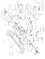
- Fig. 2 the device according to the invention is shown as an exploded view.
- the same reference numerals mean the same parts.
- the illustrations show a clamping and twisting device 1 b, 1 a, which is suspended in each case on the wing 100. This arrangement is preferable for mechanical reasons. However, it is quite possible, the clamping and twisting device 1b, 1 a in each case or partially hang on the rudder 200. In this case, however, the larger lever forces occurring due to the higher weight of the rudder 200 are to be considered in the design of, for example, the servomotor 9, 10 or the gears 8, 11.
- the illustrations show a respectively arranged along the rotation axis D clamping device 1b and a twisting device 1a.
- the devices such that parts of the clamping and / or twisting device 1b, 1a are outside the axis of rotation D. This can e.g. be done by suitable joints, which will be discussed below.
- the clamping device 1 b is based on the principle that for clamping a mandrel 2 is moved into a clamping sleeve 3. As a result, the clamping sleeve 3 is widened and pressed against the rudder 200 or against the rudder 200 and the wing 100. Suitably, the clamping sleeve 3 is pressed against a fixedly connected to the rudder 200 and the wing 100 collet 40a, 40b. Furthermore, a clamping by means of a loose clamping sleeve 3, which simultaneously presses against wings 100 and rudder 200 done.
- the collet suitably consists of a rudder-side clamping fitting 40a and a wing-side clamping fitting 40b, each having a bushing with a through hole along the axis of rotation D.
- the two clamping fittings 40a, 40b are respectively fixed to the wing 100 and the rudder 200, e.g. fastened by means of a screw connection, and have recesses, so that the two fittings 40a, 40b engage in the intended construction of wing 100 and rudder 200, so that the holes in the sockets of the two fittings 40a, 40b form a continuous bore along the axis of rotation D.
- the bush of one fitting 40a engages in the recess of the other fitting 40b.
- the clamping sleeve 3 is advantageously located in the bore of the socket of the fortified at the rudder 200 fitting 40 a.
- the clamping sleeve 3 can also be arranged in a region of the continuous bore, so that when the clamping sleeve 3 expands, it is tensioned against the rudder 200 and the wing 100. This ensures that in the tensioned state of the clamping sleeve 3 reduces the occurring game in the axis of rotation D.
- the clamping of the clamping sleeve 3 against the rudder 200 or against the wing 100 and the rudder 200 is achieved by means of a mandrel 2, which is moved to clamp the clamping sleeve 3 in this up to a predeterminable end stop.
- the clamping sleeve 3 may be formed as a hollow cylindrical sleeve with a closed jacket. In the region of the conical ends, the sleeve 3 is elastically deformed during clamping. If larger clamping forces are required, the clamping sleeve 3 can also be axially slotted in the region of the conical ends or over the entire length, in order to allow larger diameter changes for the clamping operation.
- the inner cone of the clamping sleeve 3 and the outer cone of the mandrel 2 are chosen so that upon reaching the end stop rotation of the mandrel 2 is prevented by frictional engagement.
- a rotation 4 is attached, which prevents the clamping sleeve 3 can rotate about the axis of rotation D, and is supported on the wing 100.
- wing 100 may be e.g. a recess may be provided into which the anti-rotation lock 4 engages.
- the anti-rotation 4 may suitably be a bulge, which is carried out on the outside of the clamping sleeve 3.
- the anti-rotation 4 may also be a sleeve member which is connected along the axis of rotation D with the clamping sleeve 3 and through which the mandrel 2 can pass.
- the inner diameter of the sleeve member 4 is expediently larger than the maximum outer diameter of the mandrel. 2
- An anti-rotation 4 is not required and the function of a rotation can also be taken directly from the clamping sleeve, if this is additionally braced against the clamping fittings 40a and 40b.
- the movement of the mandrel 2 is expediently by means of one of a threaded spindle 6a with a helical groove and a spindle nut 6b existing ball screw 6 reaches, which converts the rotational (rotating) movement of a drive shaft used for the drive 70 of a servomotor 9 in a translatory (linear) movement.
- the ball screw 6 is connected at one end via a ball thrust joint 5 with the mandrel 2 and at the other end via a drive joint 7 with the drive shaft 70 of the servomotor 9.
- a ball thrust joint 5 with the mandrel 2
- a drive joint 7 with the drive shaft 70 of the servomotor 9.
- the ball thrust joint 5 essentially consists of a joint ball 5 a, which is held movably in a joint shell 5 b, and located in a joint housing 5 c.
- the joint ball 5 a is expediently connected to the mandrel 2 and the joint shell 5 b with the ball screw 6 or vice versa.
- a servo motor 9 is fastened to the wing 100, which is expediently connected to the drive joint 7 via a gear 8, for example, a planetary gear.
- the arrangement of servo motor 9, which is incorporated in a motor housing 9b and gear 8 is suitably by means of a motor mount 9c, which is supported on the wing 100, stored.
- the drive joint 7 advantageously comprises a drive housing 7b and a hinge 7a mounted so as to be non-rotatably displaceable in the longitudinal direction in the housing 7b.
- the housing 7b is expediently connected to the drive shaft 70 of the servomotor 9, the joint 7a to the ball screw 6.
- the inner contour of the housing 7b corresponds to the outer contour of the joint 7a.
- the housing 7b for example, have an inner contour of a hexagon, in which the joint 7a with an outer contour of a hexagon is rotatable feasible.
- the joint 7a is guided between a first and second position in the housing. With the drive joint 7, the linear movement of the mandrel 2 is compensated by the ball screw 6, so that a continuous drive with simultaneous linear movement of the mandrel 2 is possible.
- Fig. 1 shows a clamping device according to the invention, in which all components along the axis of rotation D are arranged.
- the drive shaft 70 of the electric motor 9, the electric motor 9 itself, the drive joint 7, the ball screw 6 and the ball thrust joint 5 are arranged in a line outside the rotation axis D.
- the mandrel 2 connected to the ball screw 6 in a linear movement can be arranged between mandrel 2 and ball screw 6, for example, a flexible shaft.
- the rudder 200 is suitably mounted at the two narrow ends by means of a fitting 30 a, 30 b on the wing 100.
- This bearing fitting 30a, 30b is based essentially on the same principle as the clamping fitting 40a, 40b, however, the bearing fitting 30a, 30b has a bearing pin 30c in the continuous bores through the rudder and wing-side part of the fitting.
- the Fig. 1 and 2 also show the twisting device according to the invention.
- the twisting device 1 a comprises a servomotor 10 with a drive shaft 60.
- the servomotor 10 is expediently inserted in a motor housing 10b.
- the twisting device 1 a is suitably attached to the wing 100 and mounted by means of a motor mount 10 a.
- the drive shaft 60 is arranged in particular along the axis of rotation D.
- the servomotor 10 is also arranged in the axis of rotation D, but it is possible, the servo motor 10 outside Positioning axis of rotation D and drive the drive shaft 60, for example via a flexible shaft.
- a corresponding positive fit or cam 50 e.g. a screw or a threaded pin is provided, which connects the drive shaft 60 with the rudder 200.
- the turning device comprises a device 13 connected to the servomotor with which the angle of rotation of the drive shaft 60 can be determined.
- suitable means 20 are available for determining the zero position of the wing to the flap.
- an inductive or optical proximity switch 20 is present.
- a corresponding means which triggers the proximity switch may e.g. be firmly connected to the drive shaft 60 of the twisting device 1a.
- the means 20 may be e.g. Also, a fixed to the drive shaft 60 or the ball screw 6 connected sleeve, which has a light-dark transition in an optical proximity switch and a transition of a non-magnetic material to a magnetic material in an inductive proximity switch.
- the electric motor 10 has means which bring about a shutdown of the electric motor 10 when the torque exceeds a predefinable value. Thereby, the destruction of the electric motor and the twisting device is prevented if the clamping device is brought into a position in which the mandrel presses against the clamping sleeve and so a clamping between the rudder and wing is reached.
- the clamping is first released, wherein the mandrel is moved out of the clamping sleeve.
- the rudder is set in the desired angular position.
- the rudder is brought to zero position until the proximity switch responds. Conveniently, to avoid ambiguity, this position may be outside the nominal displacement range (e.g., -30 ° to 30 °) at e.g. -40 °.
- the rudder is moved beyond the other end of the adjustment range to avoid hysteresis errors (e.g., backlash compensation). Thereafter, only the final angular position is approached.
- the nominal adjustment range is understood to be that angular range which the movable second flap is intended to cover with respect to the first flap.
- the zero position can be set either above or below this nominal adjustment range.
- the clamping is activated again by the mandrel is pressed into the clamping sleeve with a defined force.
- the clamping motor is limited to a maximum current and thus to a maximum torque.
- the mandrel position achieved thereby serves as a zero reference of the clamping. If this zero reference value deviates by a certain size during the next closing operation, this is defined and displayed as an error case.
- the electrical components of the device according to the invention can be suitably controlled electronically over a long distance. This control can also be wireless.
- control hardware is partially or completely in the immediate vicinity of the adjustment and clamping device.
Abstract
Description
Die Erfindung betrifft eine Einrichtung gemäß dem Oberbegriff des Patentanspruchs 1.The invention relates to a device according to the preamble of patent claim 1.
Scharniere sind als Einrichtung zum Verdrehen zweier beweglicher Klappen um eine Drehachse bekannt. Scharniere bestehen üblicherweise aus zwei Buchsen, welche jeweils mit einer Klappe fest verbunden sind und einer Achse, welche die beiden Buchsen entlang der Drehachse verbindet. Nachteilig bei bekannten Scharnieren ist das Feststellen der beweglichen Klappen bei einem vorgebbaren Winkel zueinander. Dies kann üblicherweise mittels Schraubverbindungen durch eine Buchse und die Achse oder entsprechende die beiden Klappen verbindenden Winkelstücke erfolgen.Hinges are known as a device for rotating two movable flaps about an axis of rotation. Hinges usually consist of two bushes, which are each firmly connected to a flap and an axis which connects the two bushes along the axis of rotation. A disadvantage of known hinges is the detection of the movable flaps at a predeterminable angle to each other. This can usually be done by means of screw through a socket and the axis or corresponding the two flaps connecting elbows.
In der Luftfahrt sind Einrichtungen zum Verdrehen beweglicher Klappen beispielsweise bei einer Flügel-Landeklappenanordnung bekannt. Diese Anordnung zeichnet sich im Wesentlichen durch einen komplizierten Aufbau mehrerer Hebel und Gelenke aus, welche den Flügel mit der Klappe verbinden. Diese Anordnung wird üblicherweise mit Hydraulikzylindern oder mittels eines Elektromotors mit einem hohen Drehmoment angetrieben. Der Motor ist in der Lage durch das hohe Drehmoment den Hebel-Gelenk-Aufbau zu blockieren und so ein Feststellen der Klappe in einer vorgebbaren Winkelposition zum Flügel zu erreichen.In aviation devices for rotating movable flaps are known, for example in a wing flaps assembly. This arrangement is characterized essentially by a complicated structure of several levers and joints, which connect the wing with the flap. This arrangement is usually driven by hydraulic cylinders or by means of a high torque electric motor. The engine is able to block the lever-joint structure due to the high torque and thus to achieve a determination of the flap in a predetermined angular position to the wing.
Im Modellbau bei z.B. Flugzeuge, Schiffe etc. werden kleine Hebelkonstruktionen, Drehwellen o.ä. verwendet, welche mit im Rumpf oder Flügel angeordneten Servomotoren angetrieben werden. Diese Servomotoren sind üblicherweise so ausgelegt, dass sie die auf die Klappen oder Ruder wirkenden äußeren Kräfte halten können. Somit ist ein stufenloses Verstellen der Klappen möglich. Das Feststellen der Klappen in einer bestimmten Winkelposition erfolgt durch das Drehmoment des Servomotors.In the model construction with eg airplanes, ships etc. are small lever constructions, rotating shafts or similar. used, which are driven by arranged in the fuselage or wing servomotors. These servomotors are usually designed to hold the external forces acting on the flaps or rudders. Thus, a continuous adjustment of the flaps is possible. The determination of the flaps in a certain angular position is effected by the torque of the servomotor.
Bei Windkanalmodellen tritt allerdings das Problem auf, dass selbst kleinste Hebelkonstruktionen aufgrund des geringen Platzangebots meist nicht realisierbar sind. Auch lassen sich aufgrund des geringen verfügbaren Platzes im Rumpf des Windkanalmodells oft keine geeigneten Servomotoren einbauen. Üblicherweise werden bei Windkanalmodellen die zu untersuchenden Klappenstellungen manuell eingestellt, wobei mit Schraubverbindungen die Klappe in der entsprechenden Position fixiert wird. Ein stufenloses Verstellen der Klappe ist so kaum möglich. Bei Windkanalversuchen bedeutet dies für jede zu untersuchende Position ein Aus- und Einschalten, sowie ein Öffnen des Windkanals.In wind tunnel models, however, the problem arises that even the smallest lever designs are usually not feasible due to the limited space available. Also can be installed due to the small space available in the fuselage of the wind tunnel model often no suitable servomotors. Usually, the flap positions to be examined are set manually in wind tunnel models, the flap being fixed in the corresponding position with screw connections. A continuous adjustment of the flap is hardly possible. In wind tunnel tests, this means for each position to be tested a switching on and off, as well as an opening of the wind tunnel.
Es ist Aufgabe der Erfindung eine Vorrichtung anzugeben, mit welcher ein stufenloses Verdrehen und Klemmen zweier zueinander beweglicher Klappen auch bei geringem Platzangebot einfach möglich ist.It is an object of the invention to provide a device with which a continuous rotation and clamping two mutually movable flaps is easily possible even with little space.
Diese Aufgabe wird mit der Vorrichtung gemäß den Merkmalen des Anspruchs 1 gelöst.This object is achieved with the device according to the features of claim 1.
Die Klemmeinrichtung weist erfindungsgemäß eine in der Drehachse angeordnete Spannhülse auf. Diese Spannhülse ist gegen die erste Klappe, z.B. den Flügel oder gleichzeitig gegen die erste Klappe und die zweite bewegliche Klappe, z.B. Landeklappe spannbar. Um die Spanhülse gegen die Klappe oder Klappen zu spannen ist zweckmäßig ein Spanndorn vorhanden, welcher in die Spannhülse lösbar einbringbar ist. Das Einbringen des Spanndorns bewirkt ein Aufweiten der Spannhülse, wodurch diese gegen die Klappe oder die Klappen gespannt wird.The clamping device according to the invention has a clamping sleeve arranged in the axis of rotation. This clamping sleeve is against the first flap, e.g. the wing or at the same time against the first flap and the second movable flap, e.g. Landing flap tensioned. In order to tension the chip sleeve against the flap or flaps is expediently a mandrel available, which is releasably insertable into the clamping sleeve. The introduction of the mandrel causes an expansion of the clamping sleeve, whereby it is stretched against the flap or the flaps.
Im Weiteren werden ohne Beschränkung der Allgemeinheit die erste Klappe als Flügel und die zweite bewegliche Klappe als Ruder bezeichnet.In addition, the first flap is referred to as a wing and the second movable flap as a rudder without limiting the generality.
Die Verdreheinrichtung kann am Flügel oder am Ruder befestigt sein. Aus Gewichtsgründen ist die Welle der Verdreheinrichtung zweckmäßig am Flügel befestigt und gelagert. Erfindungsgemäß weist die Verdreheinrichtung eine um die Drehachse gelagerte antreibbare Welle auf. Die Welle ist dabei erfindungsgemäß mit dem Ruder (wenn die Welle am Flügel gelagert ist) oder dem Flügel (wenn die Welle am Ruder gelagert ist) über einen Mitnehmer verbunden. Diese Verbindung kann z.B. eineThe twisting device can be attached to the wing or the rudder. For weight reasons, the shaft of the twisting device is suitably attached to the wing and stored. According to the invention, the twisting device has one around the Rotary axis mounted drivable shaft. The shaft is according to the invention with the rudder (when the shaft is mounted on the wing) or the wing (when the shaft is mounted on the rudder) connected via a driver. This connection can eg a
Niet-, Stift- oder Schraubverbindung sein, welche eine starre, aber lösbare Verbindung zwischen der Welle und dem Ruder oder Flügel herstellt.Rivet, pin or screw connection, which establishes a rigid, but releasable connection between the shaft and the rudder or wing.
Die Erfindung sowie weitere vorteilhafte Ausgestaltungen der Erfindungen werden im Folgenden anhand von Zeichnungen näher erläutert. Es zeigen
- Fig. 1
- eine Schnittdarstellung durch eine Flügel-Ruderanordnung mit einer erfindungsgemäßen Vorrichtung zum Verdrehen und Klemmen des Ruders in einer beispielhaften Ausführungsform,
- Fig. 2
- eine Explosionsdarstellung einer Flügel-Ruderanordnung mit einer erfindungsgemäßen Vorrichtung zum Verdrehen und Klemmen des Ruders in einer beispielhaften Ausführungsform.
- Fig. 1
- 1 is a sectional view through a wing-rudder assembly with a device according to the invention for twisting and clamping the rudder in an exemplary embodiment,
- Fig. 2
- an exploded view of a wing-rudder assembly with a device according to the invention for twisting and clamping the rudder in an exemplary embodiment.
Die Darstellungen zeigen eine Klemm- und Verdreheinrichtung 1 b, 1 a, welche jeweils am Flügel 100 aufgehängt ist. Diese Anordnung ist aus mechanischen Gründen zu bevorzugen. Es ist aber durchaus möglich, die Klemm- und Verdreheinrichtung 1b, 1 a jeweils oder teilweise am Ruder 200 aufzuhängen. In diesem Fall sind allerdings die aufgrund des höheren Gewichts des Ruders 200 auftretenden größeren Hebelkräfte bei der Auslegung z.B. des Servomotors 9,10 oder der Getriebe 8, 11 zu berücksichtigen.The illustrations show a clamping and
Die Darstellungen zeigt eine jeweils entlang der Drehachse D angeordnete Klemmeinrichtung 1b sowie eine Verdreheinrichtung 1a. Es ist allerdings möglich, die Einrichtungen derart anzuordnen, dass Teile der Klemm- und/oder Verdreheinrichtung 1b, 1a außerhalb der Drehachse D liegen. Dies kann z.B. durch geeignete Gelenke erfolgen, worauf weiter unten noch eingegangen wird.The illustrations show a respectively arranged along the rotation axis
Die Klemmeinrichtung 1 b basiert auf dem Prinzip, dass zum Klemmen ein Spanndorn 2 in eine Spannhülse 3 hineinbewegt wird. Dadurch wird die Spannhülse 3 geweitet und gegen das Ruder 200 oder gegen das Ruder 200 und den Flügel 100 gedrückt. Zweckmäßig wird die Spannhülse 3 gegen eine fest mit dem Ruder 200 und dem Flügel 100 verbundene Spannzange 40a, 40b gedrückt. Weiterhin kann eine Klemmung auch mittels einer losen Spannhülse 3, welche gleichzeitig gegen Flügel 100 und Ruder 200 drückt, erfolgen.The
Die Spannzange besteht in geeigneter Weise aus einem ruderseitigen Spanbeschlag 40a und einem flügelseitigen Spannbeschlag 40b, welche jeweils eine Buchse mit einer Durchgangsbohrung entlang der Drehachse D aufweisen. Die beiden Spannbeschläge 40a, 40b sind jeweils am Flügel 100 und am Ruder 200 z.B. mittels einer Schraubverbindung befestigt, und weisen Ausnehmungen auf, so dass die beiden Beschläge 40a, 40b im bestimmungsgemäßen Aufbau von Flügel 100 und Ruder 200 ineinandergreifen, so dass die Bohrungen in den Buchsen der beiden Beschläge 40a, 40b eine durchgängige Bohrung entlang der Drehachse D bilden. Zweckmäßig greift dabei die Buchse des einen Beschlags 40a in die Ausnehmung des anderen Beschlags 40b ein.The collet suitably consists of a rudder-side clamping fitting 40a and a wing-side clamping fitting 40b, each having a bushing with a through hole along the axis of rotation D. The two
Die Spannhülse 3 befindet sich vorteilhaft in der Bohrung der Buchse des am Ruder 200 befestigten Beschlags 40a. In einer weiteren Ausführungsform kann die Spannhülse 3 aber auch in einem Bereich der durchgängigen Bohrung angeordnet sein, so dass beim Weiten der Spannhülse 3 diese gegen das Ruder 200 und den Flügel 100 gespannt wird. Dadurch wird erreicht das sich im gespannten Zustand der Spannhülse 3 das auftretende Spiel in der Drehachse D verringert.The
Die Klemmung der Spannhülse 3 gegen das Ruder 200 oder gegen den Flügel 100 und das Ruder 200 wird mittels eines Spanndorns 2 erreicht, welcher zur Klemmung der Spannhülse 3 in diese bis zu einem vorgebbaren Endanschlag hineinbewegt wird. Die Spannhülse 3 kann als hohlzylindrische Hülse mit geschlossenem Mantel ausgebildet sein. Im Bereich der konischen Enden wird die Hülse 3 beim Spannen elastisch verformt. Sind größere Spannkräfte erforderlich, so kann die Spannhülse 3 auch im Bereich der konischen Enden oder über die gesamte Länge axial geschlitzt sein, um größere Durchmesseränderungen für den Klemmvorgang zu ermöglichen. Der Innenkonus der Spannhülse 3 und der Außenkonus des Spanndorns 2 sind so gewählt, dass beim Erreichen des Endanschlags eine Drehung des Spanndorns 2 durch Reibschluss verhindert ist.The clamping of the
An der Spannhülse 3 ist vorteilhaft eine Verdrehsicherung 4 angebracht, welche verhindert, dass sich die Spannhülse 3 um die Drehachse D drehen kann, und sich am Flügel 100 abstützt. Hierfür kann am Flügel 100 z.B. eine Ausnehmung vorgesehen sein, in welche die Verdrehsicherung 4 eingreift. Die Verdrehsicherung 4 kann zweckmäßig eine Ausbuchtung sein, welche an der Außenseite der Spannhülse 3 ausgeführt ist.On the clamping
Die Verdrehsicherung 4 kann aber auch ein Hülsenelement sein, welches entlang der Drehachse D mit der Spannhülse 3 verbunden ist und durch welches der Spanndorn 2 durchgreifen kann. Der Innendurchmesser des Hülsenelements 4 ist dabei zweckmäßig größer als der maximale Außendurchmesser des Spanndorns 2.The
Eine Verdrehsicherung 4 ist nicht erforderlich und die Funktion einer Verdrehsicherung kann auch von der Spannhülse direkt übernommen werden, wenn diese zusätzlich gegen die Spannbeschläge 40a und 40b verspannt wird.An
Die Bewegung des Spanndorns 2 wird zweckmäßig mittels eines aus einer Gewindespindel 6a mit einer schraubenförmigen Rille und einer Spindelmutter 6b bestehenden Kugelgewindetriebs 6 erreicht, welcher die rotatorische (drehende) Bewegung einer zweckmäßig für den Antrieb verwendeten Antriebswelle 70 eines Servomotors 9 in eine translatorische (lineare) Bewegung umsetzt.The movement of the
Der Kugelgewindetrieb 6 ist am einen Ende über ein Kugel-Schubgelenk 5 mit dem Spanndorn 2 und am anderen Ende über ein Antriebsgelenk 7 mit der Antriebswelle 70 des Servomotors 9 verbunden. Mittels des Kugel-Schubgelenks 5 ist es möglich, Spannungen welche radial auf die Drehachse D wirken auszugleichen. Dadurch wird z.B. gewährleistet, dass Verkantungen des Spanndorns 2 beim Hineinbewegen in die Spannhülse 3 radial auf die Drehachse wirkende Kräfte, welche auf die Antriebswelle 70 des Servomotors 9 übertragen werden können, vermieden werden.The
Das Kugel-Schubgelenk 5 besteht im Wesentlichen aus einer Gelenkkugel 5a, welche in ein einer Gelenkschale 5b beweglich gehalten ist, und sich in einem Gelenkgehäuse 5c befinden. Die Gelenkkugel 5a ist dabei zweckmäßig mit dem Spanndorn 2 und die Gelenkschale 5b mit dem Kugelgewindetrieb 6 oder umgekehrt verbunden.The ball thrust
Zum Antreiben der Klemmeinrichtung 1 n ist am Flügel 100 ein Servomotor 9 befestigt, welcher zweckmäßig über ein Getriebe 8, z.B., ein Planetengetriebe mit dem Antriebsgelenk 7 verbunden ist. Die Anordnung aus Servomotor 9, welcher in einem Motorgehäuse 9b eingebracht ist und Getriebe 8 ist zweckmäßig mittels eines Motorträgers 9c, welcher sich am Flügel 100 abstützt, gelagert.For driving the clamping device 1 n, a
Das Antriebsgelenk 7 umfasst vorteilhaft ein Antriebsgehäuse 7b und ein in dem Gehäuse 7b verdrehsicher in Längsrichtung verschiebbar gelagertes Gelenk 7a. Das Gehäuse 7b ist zweckmäßig mit der Antriebswelle 70 des Servomotors 9 verbunden, das Gelenk 7a mit dem Kugelgewindetrieb 6.The drive joint 7 advantageously comprises a drive housing 7b and a
Dabei entspricht insbesondere die Innenkontur des Gehäuses 7b der Außenkontur des Gelenkes 7a. So kann das Gehäuse 7b z.B. eine Innenkontur eines Sechskant aufweisen, in welcher das Gelenk 7a mit einer Außenkontur eines Sechskant verdrehsicher führbar ist. Das Gelenk 7a wird dabei zwischen einer ersten und zweiten Position in dem Gehäuse geführt. Mit dem Antriebsgelenk 7 wird die Linearbewegung des Spanndorns 2 durch den Kugelgewindetrieb 6 ausgeglichen, so dass ein kontinuierlicher Antrieb bei gleichzeitiger Linearbewegung des Spanndorns 2 möglich ist.In particular, the inner contour of the housing 7b corresponds to the outer contour of the joint 7a. Thus, the housing 7b, for example, have an inner contour of a hexagon, in which the joint 7a with an outer contour of a hexagon is rotatable feasible. The joint 7a is guided between a first and second position in the housing. With the
Das Ruder 200 ist zweckmäßig an den beiden schmalen Enden mittels eines Beschlags 30a, 30b am Flügel 100 gelagert. Dieser Lagerbeschlag 30a, 30b basiert im Wesentlichen auf dem gleichen Prinzip wie der Spannbeschlag 40a, 40b, allerdings weist der Lagerbeschlag 30a, 30b in der durchgängigen Bohrungen durch den ruder- und flügelseitigen Teil des Beschlags einen Lagerbolzen 30c auf.The
Im ungeklemmten Zustand sind alle Komponenten der Klemmeinrichtung 1 b, welche mit der Antriebswelle 70 verbunden sind, frei drehbar.In the unclamped state, all components of the
Die
Zur Übertragung der Drehbewegung der Antriebswelle 60 auf das Ruder 200 ist ein entsprechender Formschluss oder ein Mitnehmer 50, z.B. eine Schraube oder ein Gewindestift vorgesehen, welcher die Antriebswelle 60 mit dem Ruder 200 verbindet. Dadurch ist es möglich, dass durch die Drehung der vom Servomotor 10 angetriebenen Antriebswelle 60 das Ruder 200 um die Drehachse D gedreht wird.To transmit the rotational movement of the
Zweckmäßig umfasst die Verdreheinrichtung eine mit dem Servomotor verbundene Einrichtung 13, mit welcher der Drehwinkel der Antriebswelle 60 bestimmt werden kann.Expediently, the turning device comprises a
Außerdem sind zweckmäßig Mittel 20 vorhanden zur Bestimmung der Nulllage des Flügels zur Klappe. Hierzu ist im Flügel z.B. ein induktiver oder optischer Näherungsschalter 20 vorhanden. Am Ruder befindet sich bei Nulllage des Ruders zum Flügel gegenüber vom Näherungsschalter 20 ein entsprechendes Mittel, welches den Näherungsschalter auslöst. Dieses Mittel 20 kann z.B. fest mit der Antriebswelle 60 der Verdreheinrichtung 1a verbunden sein. Bei dem Mittel 20 kann es sich z.B. auch um eine mit der Antriebswelle 60 oder dem Kugel-Gewindetrieb 6 fest verbundenen Hülse handeln, welche bei einem optischen Näherungsschalter einen Hell-Dunkel-Übergang und bei einem induktiven Näherungsschalter einen Übergang eines nichtmagnetischen Materials zu einem magnetischen Material aufweist.In addition, suitable means 20 are available for determining the zero position of the wing to the flap. For this purpose, in the wing e.g. an inductive or optical proximity switch 20 is present. At the rudder is at zero position of the rudder to the wing opposite the proximity switch 20, a corresponding means which triggers the proximity switch. This means 20 may e.g. be firmly connected to the
Zweckmäßig weist der Elektromotor 10 Mittel auf, welche eine Abschaltung des Elektromotors 10 bewirken, wenn das Drehmoment einen vorgebbare Wert übersteigt. Dadurch wird die Zerstörung des Elektromotors und der Verdreheinrichtung verhindert, falls die Klemmeinrichtung in eine Position gebracht ist, in welcher der Spanndorn gegen die Spannhülse drückt und so eine Klemmung zwischen Ruder und Flügel erreicht ist.Expediently, the
Beim Betrieb der erfindungsgemäßen Vorrichtung wird zuerst die Klemmung gelöst, wobei der Spanndorn aus der Spannhülse hinausbewegt wird.During operation of the device according to the invention, the clamping is first released, wherein the mandrel is moved out of the clamping sleeve.
Anschließend wird mittels Ansteuerung des Servomotors der Verdreheinrichtung das Ruder in die gewünschte Winkelposition gestellt. In einem ersten Schritt wird das Ruder in Null-Lage bis zum Ansprechen des Näherungsschalters gebracht. Diese Position kann zweckmäßigerweise - um eine Mehrdeutigkeit zu vermeiden - außerhalb des Nennverstellbereichs (z.B. -30° bis 30°) bei z.B. -40° liegen. Nachdem die Null-Lage bestimmt ist, wird das Ruder zur Vermeidung von Hysteresefehlern (z.B. Ausgleich des Getriebespiels) über das andere Ende des Verstellbereichs hinaus bewegt. Danach wird erst die endgültige Winkelposition angefahren.Subsequently, by controlling the servomotor of the turning device, the rudder is set in the desired angular position. In a first step, the rudder is brought to zero position until the proximity switch responds. Conveniently, to avoid ambiguity, this position may be outside the nominal displacement range (e.g., -30 ° to 30 °) at e.g. -40 °. After the zero position is determined, the rudder is moved beyond the other end of the adjustment range to avoid hysteresis errors (e.g., backlash compensation). Thereafter, only the final angular position is approached.
Unter dem Nennverstellbereich wird derjenige Winkelbereich verstanden, welchen die bewegliche zweite Klappe gegenüber der ersten Klappe abdecken soll. Die Null-Lage kann entweder oberhalb oder unterhalb dieses Nennverstellbereichs festgelegt werden.The nominal adjustment range is understood to be that angular range which the movable second flap is intended to cover with respect to the first flap. The zero position can be set either above or below this nominal adjustment range.
Nach erfolgter Verstellung der Klappe wird die Klemmung wieder aktiviert, indem der Spanndorn in die Spannhülse mit definierter Kraft hineingedrückt wird. Der Klemmmotor wird auf eine maximale Stromstärke und somit auf ein maximales Drehmoment begrenzt. Die dadurch erreichte Dornposition dient als Nullreferenz der Klemmung. Weicht dieser Nullreferenzwert um eine bestimmte Größe beim nächsten Schließvorgang ab, so wird dies als Fehlerfall definiert und angezeigt.After adjustment of the flap, the clamping is activated again by the mandrel is pressed into the clamping sleeve with a defined force. The clamping motor is limited to a maximum current and thus to a maximum torque. The mandrel position achieved thereby serves as a zero reference of the clamping. If this zero reference value deviates by a certain size during the next closing operation, this is defined and displayed as an error case.
Die elektrischen Komponenten der erfindungsgemäßen Vorrichtung können zweckmäßig über eine weite Entfernung elektronisch angesteuert werden ist. Diese Ansteuerung kann auch drahtlos erfolgen.The electrical components of the device according to the invention can be suitably controlled electronically over a long distance. This control can also be wireless.
Zweckmäßig befindet sich die Steuerungshardware teilweise oder vollständig in unmittelbarer Nähe der Verstell- und Klemmeinrichtung.Suitably, the control hardware is partially or completely in the immediate vicinity of the adjustment and clamping device.
Claims (10)
dadurch gekennzeichnet, dass
die Klemmeinrichtung (1b) eine gegen die erste Klappe (100) und zweite Klappe (200) spannbare oder eine gegen die zweite Klappe (200) spannbare und sich gegen die erste Klappe (100) abstützende oder eine gegen die erste Klappe (100) spannbare und sich gegen die zweite Klappe (200) abstützende und in der Drehachse D angeordnete Spannhülse (3) aufweist und
die Verdreheinrichtung (1a) eine an einer Klappe (100, 200) um die Drehachse D drehbar gelagerte antreibbare Welle (60) mit einem mit der anderen Klappe (200, 100) verbundenen Mitnehmer (50) oder Formschluss aufweist.Device for rotating and clamping a second flap (200) movable relative to a first flap (100) about a rotation axis D, comprising a twisting device (1a) and a clamping device (1b),
characterized in that
the clamping device (1b) is tensionable against the first flap (100) and second flap (200) or tensionable against the second flap (200) and against the first flap (100) or tensionable against the first flap (100) and against the second flap (200) supporting and arranged in the axis of rotation D clamping sleeve (3) and has
the twisting device (1a) has a drivable shaft (60) rotatably mounted on a flap (100, 200) about the axis of rotation D with a driver (50) connected to the other flap (200, 100) or positive locking.
Applications Claiming Priority (1)
| Application Number | Priority Date | Filing Date | Title |
|---|---|---|---|
| DE200710018189 DE102007018189B4 (en) | 2007-04-18 | 2007-04-18 | Device for twisting and clamping movable flaps |
Publications (3)
| Publication Number | Publication Date |
|---|---|
| EP1983203A2 true EP1983203A2 (en) | 2008-10-22 |
| EP1983203A3 EP1983203A3 (en) | 2012-08-01 |
| EP1983203B1 EP1983203B1 (en) | 2013-09-04 |
Family
ID=39619387
Family Applications (1)
| Application Number | Title | Priority Date | Filing Date |
|---|---|---|---|
| EP20080007261 Not-in-force EP1983203B1 (en) | 2007-04-18 | 2008-04-12 | Device for rotating and clamping moveable flaps |
Country Status (3)
| Country | Link |
|---|---|
| US (1) | US7997539B2 (en) |
| EP (1) | EP1983203B1 (en) |
| DE (1) | DE102007018189B4 (en) |
Cited By (1)
| Publication number | Priority date | Publication date | Assignee | Title |
|---|---|---|---|---|
| CN113320715A (en) * | 2021-07-07 | 2021-08-31 | 四川省天域航通科技有限公司 | Wing strength test mechanism for unmanned aerial vehicle assembly |
Families Citing this family (5)
| Publication number | Priority date | Publication date | Assignee | Title |
|---|---|---|---|---|
| DE102005008331A1 (en) * | 2005-02-23 | 2006-08-31 | Airbus Deutschland Gmbh | Shaft`s rotation angle determining device for use in aircraft, has motor detecting primary rotation data, and position pick up unit detecting secondary rotation data, where synchronization unit synchronizes both data |
| DE102010053277A1 (en) * | 2010-12-02 | 2012-06-06 | Airbus Operations Gmbh | Locking fixture, recliner fixture, component system, main wing of an aircraft wind tunnel model and aircraft wind tunnel model with such a main wing |
| CN103807286B (en) * | 2014-02-28 | 2016-08-17 | 仝达机电工业(惠州)有限公司 | A kind of automatic turning device |
| US9643716B2 (en) * | 2014-04-01 | 2017-05-09 | The Boeing Company | Air vehicle, actuator assembly and associated method of manufacture |
| CN114735175A (en) * | 2022-03-24 | 2022-07-12 | 西北工业大学 | Wing rudder angle transformation structure of towing testing machine of underwater glider |
Family Cites Families (9)
| Publication number | Priority date | Publication date | Assignee | Title |
|---|---|---|---|---|
| US2932473A (en) * | 1957-03-26 | 1960-04-12 | Martin Co | Combined hinge, structural member and actuator for aircraft control surfaces |
| DE1283603B (en) * | 1965-04-06 | 1968-11-21 | Werner Altmann | Locking device for two parts movable relative to one another about an axis of rotation |
| US3731546A (en) * | 1971-12-01 | 1973-05-08 | Sundstrand Corp | Power operable pivot joint |
| US4691582A (en) * | 1984-01-30 | 1987-09-08 | Weyer Paul P | Thin profile rotary actuator with backlash elimination |
| DE3702294C1 (en) * | 1987-01-27 | 1988-04-14 | Messerschmitt Boelkow Blohm | Actuator for wing flaps of aircraft |
| DE102004063774A1 (en) * | 2004-12-30 | 2006-07-13 | Schilling, Wolfgang | Infinitely blockable hinge comprises expanding rubber ring between two metal discs with tensile bolt to expand and press against inside wall of upper hinge part |
| DE102005031990A1 (en) * | 2005-07-08 | 2007-01-11 | Stabilus Gmbh | Device for motor- and power-operated moving a pivotable about a pivot axis flap of a vehicle |
| US7560888B2 (en) * | 2005-09-08 | 2009-07-14 | Honeywell International Inc. | Electromechanical actuator including redundant, dissimilar position feedback |
| US7322545B2 (en) * | 2005-12-29 | 2008-01-29 | The Boeing Company | Structural mechanism for unlocking and engaging a controllable surface on a hinged platform (wing) |
-
2007
- 2007-04-18 DE DE200710018189 patent/DE102007018189B4/en not_active Expired - Fee Related
-
2008
- 2008-04-02 US US12/061,266 patent/US7997539B2/en not_active Expired - Fee Related
- 2008-04-12 EP EP20080007261 patent/EP1983203B1/en not_active Not-in-force
Non-Patent Citations (1)
| Title |
|---|
| None |
Cited By (1)
| Publication number | Priority date | Publication date | Assignee | Title |
|---|---|---|---|---|
| CN113320715A (en) * | 2021-07-07 | 2021-08-31 | 四川省天域航通科技有限公司 | Wing strength test mechanism for unmanned aerial vehicle assembly |
Also Published As
| Publication number | Publication date |
|---|---|
| DE102007018189A1 (en) | 2008-10-30 |
| DE102007018189B4 (en) | 2010-06-17 |
| EP1983203B1 (en) | 2013-09-04 |
| US7997539B2 (en) | 2011-08-16 |
| EP1983203A3 (en) | 2012-08-01 |
| US20080258015A1 (en) | 2008-10-23 |
Similar Documents
| Publication | Publication Date | Title |
|---|---|---|
| DE102018212696B3 (en) | Adjustment drive for a steering column and steering column for a motor vehicle | |
| EP3322632B1 (en) | Feedback actuator for a steering device | |
| EP1983203B1 (en) | Device for rotating and clamping moveable flaps | |
| DE60313938T2 (en) | Stabilizing fin actuator with malfunction-triggered locking mechanism | |
| DE60212303T2 (en) | Actuation system for an aerodynamic rudder | |
| EP3211271B1 (en) | Actuating arrangement and flap control system comprising the same | |
| WO2015132105A1 (en) | Steering column for a motor vehicle | |
| EP2891827B1 (en) | Electromechanically actuated decoupling device for actuators | |
| WO2002036933A1 (en) | Blowout valve assembly | |
| DE102010034843A1 (en) | Device for converting a rotary movement into an axial movement | |
| EP0731297A2 (en) | Actuator system for vehicle gear-box | |
| DE20311032U1 (en) | driving device | |
| DE102018130656A1 (en) | STEER-BY-WIRE-steering device | |
| EP3444065B1 (en) | Neutral point tensioning module | |
| DE102007027698B4 (en) | Dual Linear Actuator | |
| DE102017107887A1 (en) | Actuating device for a motor vehicle transmission and switching unit | |
| DE102017107885A1 (en) | Actuating device for a vehicle transmission | |
| DE102013214221B3 (en) | Device for blocking quick adjustment of threaded spindle of motor-driven adjustment mechanism for vehicle seat, has nut half that is moveable within recess both parallel and transverse to longitudinal axis of spindle | |
| EP2643126B1 (en) | Tool for assembling a securing ring | |
| EP2256033B1 (en) | Spindle drive | |
| EP3727770B1 (en) | Wall saw with a locking device | |
| EP2675045A2 (en) | Adjustment device | |
| EP2803802B1 (en) | Adjusting device for a door | |
| DE19605068C2 (en) | Screw connection | |
| EP3336293A1 (en) | Actuating device for a vehicle part which can be moved relative to a body of a motor vehicle |
Legal Events
| Date | Code | Title | Description |
|---|---|---|---|
| PUAI | Public reference made under article 153(3) epc to a published international application that has entered the european phase |
Free format text: ORIGINAL CODE: 0009012 |
|
| AK | Designated contracting states |
Kind code of ref document: A2 Designated state(s): AT BE BG CH CY CZ DE DK EE ES FI FR GB GR HR HU IE IS IT LI LT LU LV MC MT NL NO PL PT RO SE SI SK TR |
|
| AX | Request for extension of the european patent |
Extension state: AL BA MK RS |
|
| PUAL | Search report despatched |
Free format text: ORIGINAL CODE: 0009013 |
|
| AK | Designated contracting states |
Kind code of ref document: A3 Designated state(s): AT BE BG CH CY CZ DE DK EE ES FI FR GB GR HR HU IE IS IT LI LT LU LV MC MT NL NO PL PT RO SE SI SK TR |
|
| AX | Request for extension of the european patent |
Extension state: AL BA MK RS |
|
| RIC1 | Information provided on ipc code assigned before grant |
Ipc: F16C 11/10 20060101AFI20120628BHEP Ipc: G01M 9/08 20060101ALI20120628BHEP |
|
| 17P | Request for examination filed |
Effective date: 20130117 |
|
| GRAP | Despatch of communication of intention to grant a patent |
Free format text: ORIGINAL CODE: EPIDOSNIGR1 |
|
| AKX | Designation fees paid |
Designated state(s): CH DE FR GB LI NL |
|
| INTG | Intention to grant announced |
Effective date: 20130403 |
|
| GRAS | Grant fee paid |
Free format text: ORIGINAL CODE: EPIDOSNIGR3 |
|
| GRAA | (expected) grant |
Free format text: ORIGINAL CODE: 0009210 |
|
| AK | Designated contracting states |
Kind code of ref document: B1 Designated state(s): CH DE FR GB LI NL |
|
| REG | Reference to a national code |
Ref country code: GB Ref legal event code: FG4D Free format text: NOT ENGLISH |
|
| REG | Reference to a national code |
Ref country code: CH Ref legal event code: EP |
|
| REG | Reference to a national code |
Ref country code: DE Ref legal event code: R096 Ref document number: 502008010587 Country of ref document: DE Effective date: 20131031 |
|
| REG | Reference to a national code |
Ref country code: NL Ref legal event code: T3 |
|
| REG | Reference to a national code |
Ref country code: DE Ref legal event code: R097 Ref document number: 502008010587 Country of ref document: DE |
|
| PLBE | No opposition filed within time limit |
Free format text: ORIGINAL CODE: 0009261 |
|
| STAA | Information on the status of an ep patent application or granted ep patent |
Free format text: STATUS: NO OPPOSITION FILED WITHIN TIME LIMIT |
|
| 26N | No opposition filed |
Effective date: 20140605 |
|
| REG | Reference to a national code |
Ref country code: DE Ref legal event code: R097 Ref document number: 502008010587 Country of ref document: DE Effective date: 20140605 |
|
| REG | Reference to a national code |
Ref country code: DE Ref legal event code: R081 Ref document number: 502008010587 Country of ref document: DE Owner name: AIRBUS DEFENCE AND SPACE GMBH, DE Free format text: FORMER OWNER: EADS DEUTSCHLAND GMBH, 85521 OTTOBRUNN, DE Effective date: 20140814 |
|
| REG | Reference to a national code |
Ref country code: FR Ref legal event code: PLFP Year of fee payment: 8 |
|
| PGFP | Annual fee paid to national office [announced via postgrant information from national office to epo] |
Ref country code: NL Payment date: 20150420 Year of fee payment: 8 |
|
| PGFP | Annual fee paid to national office [announced via postgrant information from national office to epo] |
Ref country code: GB Payment date: 20150420 Year of fee payment: 8 Ref country code: DE Payment date: 20150421 Year of fee payment: 8 Ref country code: CH Payment date: 20150420 Year of fee payment: 8 |
|
| PGFP | Annual fee paid to national office [announced via postgrant information from national office to epo] |
Ref country code: FR Payment date: 20150421 Year of fee payment: 8 |
|
| REG | Reference to a national code |
Ref country code: DE Ref legal event code: R119 Ref document number: 502008010587 Country of ref document: DE |
|
| REG | Reference to a national code |
Ref country code: CH Ref legal event code: PL |
|
| REG | Reference to a national code |
Ref country code: NL Ref legal event code: MM Effective date: 20160501 |
|
| GBPC | Gb: european patent ceased through non-payment of renewal fee |
Effective date: 20160412 |
|
| REG | Reference to a national code |
Ref country code: FR Ref legal event code: ST Effective date: 20161230 |
|
| PG25 | Lapsed in a contracting state [announced via postgrant information from national office to epo] |
Ref country code: DE Free format text: LAPSE BECAUSE OF NON-PAYMENT OF DUE FEES Effective date: 20161101 Ref country code: GB Free format text: LAPSE BECAUSE OF NON-PAYMENT OF DUE FEES Effective date: 20160412 Ref country code: FR Free format text: LAPSE BECAUSE OF NON-PAYMENT OF DUE FEES Effective date: 20160502 Ref country code: LI Free format text: LAPSE BECAUSE OF NON-PAYMENT OF DUE FEES Effective date: 20160430 Ref country code: NL Free format text: LAPSE BECAUSE OF NON-PAYMENT OF DUE FEES Effective date: 20160501 Ref country code: CH Free format text: LAPSE BECAUSE OF NON-PAYMENT OF DUE FEES Effective date: 20160430 |