EP1983180A1 - Air intake control device of v-diesel engine - Google Patents
Air intake control device of v-diesel engine Download PDFInfo
- Publication number
- EP1983180A1 EP1983180A1 EP07713829A EP07713829A EP1983180A1 EP 1983180 A1 EP1983180 A1 EP 1983180A1 EP 07713829 A EP07713829 A EP 07713829A EP 07713829 A EP07713829 A EP 07713829A EP 1983180 A1 EP1983180 A1 EP 1983180A1
- Authority
- EP
- European Patent Office
- Prior art keywords
- intake
- flow rate
- air intake
- air
- diesel engine
- Prior art date
- Legal status (The legal status is an assumption and is not a legal conclusion. Google has not performed a legal analysis and makes no representation as to the accuracy of the status listed.)
- Granted
Links
Images


Classifications
-
- F—MECHANICAL ENGINEERING; LIGHTING; HEATING; WEAPONS; BLASTING
- F02—COMBUSTION ENGINES; HOT-GAS OR COMBUSTION-PRODUCT ENGINE PLANTS
- F02D—CONTROLLING COMBUSTION ENGINES
- F02D41/00—Electrical control of supply of combustible mixture or its constituents
- F02D41/02—Circuit arrangements for generating control signals
- F02D41/18—Circuit arrangements for generating control signals by measuring intake air flow
-
- F—MECHANICAL ENGINEERING; LIGHTING; HEATING; WEAPONS; BLASTING
- F02—COMBUSTION ENGINES; HOT-GAS OR COMBUSTION-PRODUCT ENGINE PLANTS
- F02B—INTERNAL-COMBUSTION PISTON ENGINES; COMBUSTION ENGINES IN GENERAL
- F02B37/00—Engines characterised by provision of pumps driven at least for part of the time by exhaust
- F02B37/007—Engines characterised by provision of pumps driven at least for part of the time by exhaust with exhaust-driven pumps arranged in parallel, e.g. at least one pump supplying alternatively
-
- F—MECHANICAL ENGINEERING; LIGHTING; HEATING; WEAPONS; BLASTING
- F02—COMBUSTION ENGINES; HOT-GAS OR COMBUSTION-PRODUCT ENGINE PLANTS
- F02D—CONTROLLING COMBUSTION ENGINES
- F02D23/00—Controlling engines characterised by their being supercharged
-
- F—MECHANICAL ENGINEERING; LIGHTING; HEATING; WEAPONS; BLASTING
- F02—COMBUSTION ENGINES; HOT-GAS OR COMBUSTION-PRODUCT ENGINE PLANTS
- F02D—CONTROLLING COMBUSTION ENGINES
- F02D41/00—Electrical control of supply of combustible mixture or its constituents
- F02D41/0002—Controlling intake air
-
- F—MECHANICAL ENGINEERING; LIGHTING; HEATING; WEAPONS; BLASTING
- F02—COMBUSTION ENGINES; HOT-GAS OR COMBUSTION-PRODUCT ENGINE PLANTS
- F02D—CONTROLLING COMBUSTION ENGINES
- F02D41/00—Electrical control of supply of combustible mixture or its constituents
- F02D41/008—Controlling each cylinder individually
- F02D41/0082—Controlling each cylinder individually per groups or banks
-
- F—MECHANICAL ENGINEERING; LIGHTING; HEATING; WEAPONS; BLASTING
- F02—COMBUSTION ENGINES; HOT-GAS OR COMBUSTION-PRODUCT ENGINE PLANTS
- F02D—CONTROLLING COMBUSTION ENGINES
- F02D9/00—Controlling engines by throttling air or fuel-and-air induction conduits or exhaust conduits
- F02D9/08—Throttle valves specially adapted therefor; Arrangements of such valves in conduits
- F02D9/10—Throttle valves specially adapted therefor; Arrangements of such valves in conduits having pivotally-mounted flaps
- F02D9/109—Throttle valves specially adapted therefor; Arrangements of such valves in conduits having pivotally-mounted flaps having two or more flaps
-
- F—MECHANICAL ENGINEERING; LIGHTING; HEATING; WEAPONS; BLASTING
- F02—COMBUSTION ENGINES; HOT-GAS OR COMBUSTION-PRODUCT ENGINE PLANTS
- F02M—SUPPLYING COMBUSTION ENGINES IN GENERAL WITH COMBUSTIBLE MIXTURES OR CONSTITUENTS THEREOF
- F02M26/00—Engine-pertinent apparatus for adding exhaust gases to combustion-air, main fuel or fuel-air mixture, e.g. by exhaust gas recirculation [EGR] systems
- F02M26/02—EGR systems specially adapted for supercharged engines
- F02M26/08—EGR systems specially adapted for supercharged engines for engines having two or more intake charge compressors or exhaust gas turbines, e.g. a turbocharger combined with an additional compressor
-
- F—MECHANICAL ENGINEERING; LIGHTING; HEATING; WEAPONS; BLASTING
- F02—COMBUSTION ENGINES; HOT-GAS OR COMBUSTION-PRODUCT ENGINE PLANTS
- F02M—SUPPLYING COMBUSTION ENGINES IN GENERAL WITH COMBUSTIBLE MIXTURES OR CONSTITUENTS THEREOF
- F02M26/00—Engine-pertinent apparatus for adding exhaust gases to combustion-air, main fuel or fuel-air mixture, e.g. by exhaust gas recirculation [EGR] systems
- F02M26/13—Arrangement or layout of EGR passages, e.g. in relation to specific engine parts or for incorporation of accessories
- F02M26/38—Arrangement or layout of EGR passages, e.g. in relation to specific engine parts or for incorporation of accessories with two or more EGR valves disposed in parallel
-
- F—MECHANICAL ENGINEERING; LIGHTING; HEATING; WEAPONS; BLASTING
- F02—COMBUSTION ENGINES; HOT-GAS OR COMBUSTION-PRODUCT ENGINE PLANTS
- F02M—SUPPLYING COMBUSTION ENGINES IN GENERAL WITH COMBUSTIBLE MIXTURES OR CONSTITUENTS THEREOF
- F02M35/00—Combustion-air cleaners, air intakes, intake silencers, or induction systems specially adapted for, or arranged on, internal-combustion engines
- F02M35/10—Air intakes; Induction systems
- F02M35/10006—Air intakes; Induction systems characterised by the position of elements of the air intake system in direction of the air intake flow, i.e. between ambient air inlet and supply to the combustion chamber
- F02M35/10026—Plenum chambers
- F02M35/10032—Plenum chambers specially shaped or arranged connecting duct between carburettor or air inlet duct and the plenum chamber; specially positioned carburettors or throttle bodies with respect to the plenum chamber
-
- F—MECHANICAL ENGINEERING; LIGHTING; HEATING; WEAPONS; BLASTING
- F02—COMBUSTION ENGINES; HOT-GAS OR COMBUSTION-PRODUCT ENGINE PLANTS
- F02M—SUPPLYING COMBUSTION ENGINES IN GENERAL WITH COMBUSTIBLE MIXTURES OR CONSTITUENTS THEREOF
- F02M35/00—Combustion-air cleaners, air intakes, intake silencers, or induction systems specially adapted for, or arranged on, internal-combustion engines
- F02M35/10—Air intakes; Induction systems
- F02M35/10006—Air intakes; Induction systems characterised by the position of elements of the air intake system in direction of the air intake flow, i.e. between ambient air inlet and supply to the combustion chamber
- F02M35/10026—Plenum chambers
- F02M35/10045—Multiple plenum chambers; Plenum chambers having inner separation walls
-
- F—MECHANICAL ENGINEERING; LIGHTING; HEATING; WEAPONS; BLASTING
- F02—COMBUSTION ENGINES; HOT-GAS OR COMBUSTION-PRODUCT ENGINE PLANTS
- F02M—SUPPLYING COMBUSTION ENGINES IN GENERAL WITH COMBUSTIBLE MIXTURES OR CONSTITUENTS THEREOF
- F02M35/00—Combustion-air cleaners, air intakes, intake silencers, or induction systems specially adapted for, or arranged on, internal-combustion engines
- F02M35/10—Air intakes; Induction systems
- F02M35/10373—Sensors for intake systems
- F02M35/10386—Sensors for intake systems for flow rate
-
- F—MECHANICAL ENGINEERING; LIGHTING; HEATING; WEAPONS; BLASTING
- F02—COMBUSTION ENGINES; HOT-GAS OR COMBUSTION-PRODUCT ENGINE PLANTS
- F02M—SUPPLYING COMBUSTION ENGINES IN GENERAL WITH COMBUSTIBLE MIXTURES OR CONSTITUENTS THEREOF
- F02M35/00—Combustion-air cleaners, air intakes, intake silencers, or induction systems specially adapted for, or arranged on, internal-combustion engines
- F02M35/10—Air intakes; Induction systems
- F02M35/104—Intake manifolds
- F02M35/116—Intake manifolds for engines with cylinders in V-arrangement or arranged oppositely relative to the main shaft
-
- F—MECHANICAL ENGINEERING; LIGHTING; HEATING; WEAPONS; BLASTING
- F01—MACHINES OR ENGINES IN GENERAL; ENGINE PLANTS IN GENERAL; STEAM ENGINES
- F01N—GAS-FLOW SILENCERS OR EXHAUST APPARATUS FOR MACHINES OR ENGINES IN GENERAL; GAS-FLOW SILENCERS OR EXHAUST APPARATUS FOR INTERNAL-COMBUSTION ENGINES
- F01N13/00—Exhaust or silencing apparatus characterised by constructional features
- F01N13/08—Other arrangements or adaptations of exhaust conduits
- F01N13/10—Other arrangements or adaptations of exhaust conduits of exhaust manifolds
- F01N13/107—More than one exhaust manifold or exhaust collector
-
- F—MECHANICAL ENGINEERING; LIGHTING; HEATING; WEAPONS; BLASTING
- F02—COMBUSTION ENGINES; HOT-GAS OR COMBUSTION-PRODUCT ENGINE PLANTS
- F02B—INTERNAL-COMBUSTION PISTON ENGINES; COMBUSTION ENGINES IN GENERAL
- F02B29/00—Engines characterised by provision for charging or scavenging not provided for in groups F02B25/00, F02B27/00 or F02B33/00 - F02B39/00; Details thereof
- F02B29/04—Cooling of air intake supply
- F02B29/0406—Layout of the intake air cooling or coolant circuit
- F02B29/0412—Multiple heat exchangers arranged in parallel or in series
-
- F—MECHANICAL ENGINEERING; LIGHTING; HEATING; WEAPONS; BLASTING
- F02—COMBUSTION ENGINES; HOT-GAS OR COMBUSTION-PRODUCT ENGINE PLANTS
- F02B—INTERNAL-COMBUSTION PISTON ENGINES; COMBUSTION ENGINES IN GENERAL
- F02B37/00—Engines characterised by provision of pumps driven at least for part of the time by exhaust
- F02B37/12—Control of the pumps
- F02B37/24—Control of the pumps by using pumps or turbines with adjustable guide vanes
-
- F—MECHANICAL ENGINEERING; LIGHTING; HEATING; WEAPONS; BLASTING
- F02—COMBUSTION ENGINES; HOT-GAS OR COMBUSTION-PRODUCT ENGINE PLANTS
- F02D—CONTROLLING COMBUSTION ENGINES
- F02D41/00—Electrical control of supply of combustible mixture or its constituents
- F02D41/0002—Controlling intake air
- F02D41/0007—Controlling intake air for control of turbo-charged or super-charged engines
-
- F—MECHANICAL ENGINEERING; LIGHTING; HEATING; WEAPONS; BLASTING
- F02—COMBUSTION ENGINES; HOT-GAS OR COMBUSTION-PRODUCT ENGINE PLANTS
- F02D—CONTROLLING COMBUSTION ENGINES
- F02D41/00—Electrical control of supply of combustible mixture or its constituents
- F02D41/22—Safety or indicating devices for abnormal conditions
- F02D41/221—Safety or indicating devices for abnormal conditions relating to the failure of actuators or electrically driven elements
-
- F—MECHANICAL ENGINEERING; LIGHTING; HEATING; WEAPONS; BLASTING
- F02—COMBUSTION ENGINES; HOT-GAS OR COMBUSTION-PRODUCT ENGINE PLANTS
- F02M—SUPPLYING COMBUSTION ENGINES IN GENERAL WITH COMBUSTIBLE MIXTURES OR CONSTITUENTS THEREOF
- F02M35/00—Combustion-air cleaners, air intakes, intake silencers, or induction systems specially adapted for, or arranged on, internal-combustion engines
- F02M35/10—Air intakes; Induction systems
- F02M35/1015—Air intakes; Induction systems characterised by the engine type
- F02M35/10157—Supercharged engines
-
- Y—GENERAL TAGGING OF NEW TECHNOLOGICAL DEVELOPMENTS; GENERAL TAGGING OF CROSS-SECTIONAL TECHNOLOGIES SPANNING OVER SEVERAL SECTIONS OF THE IPC; TECHNICAL SUBJECTS COVERED BY FORMER USPC CROSS-REFERENCE ART COLLECTIONS [XRACs] AND DIGESTS
- Y02—TECHNOLOGIES OR APPLICATIONS FOR MITIGATION OR ADAPTATION AGAINST CLIMATE CHANGE
- Y02T—CLIMATE CHANGE MITIGATION TECHNOLOGIES RELATED TO TRANSPORTATION
- Y02T10/00—Road transport of goods or passengers
- Y02T10/10—Internal combustion engine [ICE] based vehicles
- Y02T10/12—Improving ICE efficiencies
-
- Y—GENERAL TAGGING OF NEW TECHNOLOGICAL DEVELOPMENTS; GENERAL TAGGING OF CROSS-SECTIONAL TECHNOLOGIES SPANNING OVER SEVERAL SECTIONS OF THE IPC; TECHNICAL SUBJECTS COVERED BY FORMER USPC CROSS-REFERENCE ART COLLECTIONS [XRACs] AND DIGESTS
- Y02—TECHNOLOGIES OR APPLICATIONS FOR MITIGATION OR ADAPTATION AGAINST CLIMATE CHANGE
- Y02T—CLIMATE CHANGE MITIGATION TECHNOLOGIES RELATED TO TRANSPORTATION
- Y02T10/00—Road transport of goods or passengers
- Y02T10/10—Internal combustion engine [ICE] based vehicles
- Y02T10/40—Engine management systems
Definitions
- the present invention relates to an air intake control device of a V-diesel engine that controls the condition of intake air supplied to the V-diesel engine.
- an intake passage 2 of the V-engine includes a common upstream portion and branched downstream portions, which are connected to a pair of banks 1L, 1R.
- the intake air is thus distributed to the corresponding cylinders (see, for example, Patent Document 1).
- An air intake throttle valve 3, which adjusts the intake flow rate, is provided in the upstream portion of the intake passage 2, that is, in the common portion of the banks 1L, 1R.
- the common air intake throttle valve 3 is adjusted by the common air intake throttle valve 3 at the same time.
- intake passages 2L, 2R may be provided separately for the banks 1L, 1R and air intake throttle valves 3L, 3R are arranged in the corresponding intake passages 2L, 2R.
- This configuration narrows the adjustment range of the intake flow rate for each of the air intake throttle valves 3L, 3R to a half of the adjustment range of the intake flow rate required for the intake flow rate throttle valve provided commonly for the banks. The intake flow rate is thus adjusted accurately.
- an air intake control device of a V-diesel engine that accurately changes the condition of intake air by a pair of actuators provided in an intake passage and suppresses increase of load of calculation without complicating the configuration involved in control of operation of the actuators.
- an air intake control device of a V diesel engine having an intake passage through which intake air is supplied to respective cylinders formed in a pair of banks of the V diesel engine, an actuator that changes the condition of the intake air flowing in the intake passage, and control means that controls operation of the actuator.
- the intake passage includes a pair of connecting portions each connected to one of the banks, a converging portion that connects the connecting portions together, and a pair of branch portions branched from the converging portion and extending upstream.
- the actuator is provided in correspondence with each of the branch portions.
- the control means controls operation of each of the actuators in accordance with a common target control value.
- the actuators are arranged in correspondence with the branch portions of the intake passage.
- the operable range of each actuator becomes small. This allows each actuator to accurately change the condition of the intake flow rate.
- the intake air is temporarily mixed together in the converging portion of the intake passage.
- the intake air is then distributed to the banks through the corresponding connecting portions. This makes it unnecessary to control operation of the actuators separately.
- operation of the actuators is controlled in accordance with the common target control value. This prevents the structures involved in control of operation of the actuators from becoming complicated and load of calculation from increasing.
- the condition of the intake air includes, for example, the flow rate, pressure, and temperature of the intake flow rate , and the concentration and temperature of the recirculated exhaust gas in the intake air.
- the above described air intake control device of the V diesel engine preferably has a sensor that detects the condition of the intake air flowing in the intake passage.
- the sensor is preferably provided in correspondence with each of the branch portions.
- the sensors are provided in correspondence with the branch portions of the intake passage.
- the detectable range of each of the sensors becomes small. This allows each sensor to accurately detect the condition of the intake air.
- the senor preferably includes a pair of intake flow rate sensors each arranged in one of the branch portions.
- the control means preferably calculates the amount of the intake air flowing in the intake passage by averaging detection values provided by the intake flow rate sensors.
- control means preferably performs a smoothing procedure on the detection values of the intake flow rate sensors prior to the averaging procedure.
- This configuration further effectively suppresses influence by the pulsation of the intake air.
- control means preferably feedback controls operation of the actuators in accordance with the target control value.
- the control means preferably further includes determining means that determines whether there is a malfunction in the actuators, and restricting means that restricts change of the condition of the intake air through a feedback control performed on one of the actuators if the determining means determines that the other one of the actuators is malfunctioning.
- restriction of the change of the condition of the intake air includes prohibition of the change of the condition of the intake air through feedback control on one of the actuators if a malfunction of the other one of the actuators is detected.
- the V diesel engine preferably further includes a pair of superchargers arranged in correspondence with the branch portions, and a pair of boost pressure changing mechanisms each changing a boost pressure of the corresponding supercharger.
- the boost pressure changing mechanisms serve as the actuators.
- the restricting means preferably minimizes a supercharging efficiency by prohibiting the feedback control on the other one of the boost pressure changing mechanisms if the determining means determines that one of the boost pressure changing mechanisms is malfunctioning.
- the above described air intake control device of the V diesel engine preferably includes a pair of exhaust flow rate adjusting valves serving as the actuators.
- the exhaust flow rate adjusting valves are formed in a pair of communication lines each connecting an exhaust passage connected to the cylinders and the corresponding one of the branch portions to each other.
- the exhaust flow rate adjusting valves each adjust an amount of exhaust gas recirculated to the corresponding branch portions through the associated communication passage. If the determining means determines that one of the exhaust flow rate adjusting valves is malfunctioning, the restricting means fully closes the other one of the exhaust flow rate adjusting valves by prohibiting the feedback control on the exhaust flow rate adjusting valve.
- the above described air intake control device of the V diesel engine preferably includes a pair of air intake throttle valves serving as the actuators.
- the air intake throttle valves are formed in the corresponding branch portions.
- the air intake throttle valves each adjust the amount of the intake air passing through the corresponding branch portion. If the determining means determines that one of the air intake throttle valves is malfunctioning, the control means fully opens the other one of the air intake throttle valves by prohibiting the feedback control on the air intake throttle valve.
- the converging portion is preferably formed by a surge tank provided commonly for the banks.
- the intake air reliably has a volume necessary for reducing pulsation of intake air.
- the surge tank provided commonly for the banks as the converging portion, the intake air flowing from the two branch portions into the converging portion is effectively mixed together.
- the amounts and properties of the intake air sent from the converging portion to the two connecting portions thus become equal. This reduces undesirable influence caused by differences of the amounts and properties of the intake air fed to the cylinders from one bank to the other, such as variation of the engine operating speed and aggravation of the exhaust properties.
- this structure is suitable for large intake air control devices.
- an engine 10 is a V-engine, in which a pair of banks 11L, 11R are arranged in a V shape. Each of the banks 11L, 11R has four cylinders.
- An intake system of the engine 10 includes an air cleaner 12, a pair of intercoolers 14L, 14R, a throttle body 20, and superchargers 24L, 24R corresponding to the banks 11L, 11R.
- Each of the superchargers 24L, 24R is an exhaust driven type supercharger.
- Each supercharger 24L, 24R has a rotor 27.
- a compressor blade 26 and a turbine blade 25 are arranged at ends of each of the rotors 27.
- Each of the compressor blades 26 is arranged in the corresponding one of a pair of inlet lines 13L, 13R, which connect the corresponding intercoolers 14L, 14R to the air cleaner 12.
- Each of the turbine blades 25 is provided in the corresponding one of a pair of exhaust passages 21L, 21R connected to the corresponding cylinders of the banks 11L, 11R.
- Each supercharger 24L, 24R uses energy produced by the exhaust gas discharged from the cylinders into the corresponding exhaust passage 21L, 21R to supercharge the intake air.
- each rotor 27 is rotated by the exhaust gas in the corresponding exhaust passage 21L, 21R that hits the associated turbine blade 25.
- the inlet lines 13L, 13R have substantially equal cross-sectional areas and lengths.
- the compressor blades 26 are located substantially at the same positions in the inlet lines 13L, 13R.
- Each supercharger 24L, 24R has a boost pressure changing mechanism 50L, 50R.
- Each of the boost pressure changing mechanisms 50L, 50R has a nozzle (not shown) through which the exhaust gas is blasted onto the corresponding one of the turbine blades 25 and a motor (not shown) that changes the opening degree of the nozzle.
- Each boost pressure changing mechanism 50L, 50R adjusts the opening degree of the nozzle and thus changes the boost pressure.
- the boost pressure changes in correspondence with the flow velocity (more correctly, momentum) of the exhaust gas hitting the turbine blade 25.
- the boost pressure changes.
- the boost pressure thus becomes low. Contrastingly, if the engine 10 is operated in a high load and high rotation range, the flow velocity of the exhaust gas is great and the rotational speed of each rotor 27 is high. The boost pressure thus becomes high.
- each boost pressure changing mechanism 50L, 50R reduces the opening degree of the corresponding nozzle to increase the flow velocity of the exhaust gas hitting the associated turbine blade 25. This increases the boost pressure and improves supercharging response.
- the boost pressure changing mechanism 50L, 50R increases the opening degree of the nozzle to decrease the flow velocity of the exhaust gas hitting the turbine blade 25. This suppresses excessive rotation of the rotor 27 and excessive rise of boost pressure.
- each supercharger 24L, 24R is supplied to the corresponding intercooler 14L, 14R through the associated inlet line 13L, 13R.
- the intercooler 14L, 14R cools the intake air, which has been heated through compression by the supercharger 24L, 24R.
- the intake air is then introduced into the throttle body 20.
- the two superchargers 24L, 24R and the two boost pressure changing mechanisms 50L, 50R exhibit substantially the same boost characteristics and boost pressure changing characteristics.
- the intercoolers 14L, 14R have substantially identical configurations.
- the throttle body 20 has a pair of branch lines 15L, 15R, a pair of air intake throttle valves 51L, 51R provided in the corresponding branch lines 15L, 15R, and a converging line 16, which is downstream from the branch lines 15L, 15R.
- the intake air After flowing from the intercoolers 14L, 14R into the throttle body 20, the intake air is distributed to the branch lines 15L, 15R by substantially equal amounts.
- the intake air is then sent to the converging line 16 through the air intake throttle valves 51L, 51R.
- the converging line 16 functions as a surge tank provided commonly for the banks 11L, 11R.
- the cross-sectional area of the converging line 16 is greater than the cross-sectional area of each branch line 15L, 15R.
- the converging line 16 ensures a volume necessary for decreasing pulsation of the intake air.
- the branch lines 15L, 15R have substantially equal flow passage areas and lengths.
- the air intake throttle valves 51L, 51R are located substantially at the same positions in the branch lines 15L, 15R. Further, the opening/closing speeds of the air intake throttle valves 51L, 51R and the opening degrees of the air intake throttle valves 51L, 51R in the fully open/closed states are substantially equal.
- a communicating portion S which connects the branch lines 15L, 15R to each other, is provided in the throttle body 20 at a position upstream from the branch lines 15L, 15R. Some of the intake air flowing from the intercoolers 14L, 14R is mixed together in the communicating portion S before being distributed to the branch lines 15L, 15R. In this manner, the above-described differences in the condition of the intake air are eliminated to a certain extent before the intake air is distributed to the branch lines 15L, 15R.
- the communicating portion S may be omitted as long as the converging line 16 operates to eliminate the differences in the condition between the intake air flowing into the branch line 15L and the intake air flowing into the branch line 15R.
- the converging line 16 operates to mix the intake air from the branch line 15L with the intake air from the branch line 15R, thus eliminating the differences in the condition between the intake air from the branch line 15L and the intake air from the branch line 15R. Mixing of the intake air in the communicating portion S is thus performed as an auxiliary operation.
- a pair of distributing lines 19L, 19R (intake manifolds) are connected to the converging line 16.
- the downstream side of one of the distributing lines 19L, 19R is branched toward the cylinders of the left bank 11L, as viewed in Fig. 1 , and connected to the cylinders of the bank 11L.
- the downstream side of the other of the distributing lines 19L, 19R is branched toward and connected to the cylinders of the right bank 11R, as viewed in Fig. 1 .
- the branch lines 19L, 19R have substantially equal flow passage areas and passage lengths and substantially identical shapes.
- the intake air is introduced into the branch lines 19L, 19R by substantially equal amounts while being maintained in the homogeneous state.
- the intake air that has been sent to the branch lines 19L, 19R is distributed to the cylinders of the corresponding banks 11L, 11R by uniform amounts.
- the intake system of the engine 10 includes an external exhaust gas recirculating mechanism, which recirculates some of the exhaust gas from the exhaust passages 21L, 21R to the branch lines 15L, 15R (EGR).
- the external exhaust gas recirculating mechanism has a pair of recirculating lines 17L, 17R and a pair of exhaust flow rate adjusting valves 52L, 52R, which are provided in the corresponding recirculating lines 17L, 17R.
- the recirculating line 17L connects the exhaust passage 21L upstream from the supercharger 24L and the branch line 15L downstream from the air intake throttle valve 51L to each other.
- the recirculating line 17R connects the exhaust passage 21R upstream from the supercharger 24R and the branch line 15R downstream from the air intake throttle valve 51R to each other.
- the exhaust flow rate adjusting valve 52L is provided at the most downstream position in the recirculating line 17L, which is the connecting portion between the recirculating line 17L and the branch line 15L.
- the exhaust flow rate adjusting valve 52R is provided at the most downstream position in the recirculating line 17R, which is the connecting portion between the recirculating line 17R and the branch line 15R.
- the external exhaust gas recirculating mechanism operates to return some of the exhaust gas from each exhaust passage 21L, 21R to the corresponding branch line 15L, 15R through the associated recirculating line 17L, 17R, using negative intake pressure generated at a position downstream from the corresponding air intake throttle valve 51L, 51R in the branch line 15L, 15R.
- Each of the exhaust flow rate adjusting valves 52L, 52R is an electromagnetic valve driven by a motor (not shown). As the motor runs and the opening degree of each exhaust flow rate adjusting valve 52L, 52R is adjusted, the amount of the exhaust gas returned from the exhaust passage 21L, 21R to the branch line 15L, 15R, or the amount of recirculated gas, is adjusted.
- each of the air intake throttle valves 51L, 51R is an electromagnetic valve driven by a motor (not shown). As the motor operates and the opening degree of each air intake throttle valve 51L, 51R is changed, the total amount of the intake air led from the corresponding branch line 15L, 15R to the converging line 16, or the total amount of the intake air distributed from the converging line 16 to the cylinders through the distributing line 19L, 19R, is adjusted.
- each air intake throttle valve 51L, 51R is adjusted in such a manner as to suppress increase of particulate matter (PM) in the exhaust gas. Specifically, as the amount of intake air becomes excessively short compared to the amount of injected fuel, the fuel burns incompletely and thus increases the amount of the particulate matter in the exhaust gas.
- the opening degree of each air intake throttle valve 51L, 51R is thus adjusted to ensure a desired amount of intake air in correspondence with the operating state of the engine, which is represented by, for example, the fuel injection amount.
- each air intake throttle valve 51L, 51R is adjusted to ensure optimal adjustment of the intake flow rate and optimal recirculation of the exhaust gas by the external exhaust gas recirculating mechanism. If the opening degree of each exhaust flow rate adjusting valve 52L, 52R is fixed, negative pressure produced downstream from the air intake throttle valve 51L, 51R increases as the opening degree of the air intake throttle valve 51L, 51R decreases. This increases the amount of the recirculated gas recirculated from the corresponding exhaust passage 21L, 21R to the branch line 15L, 15R. Contrastingly, the negative pressure decreases as the opening degree of the air intake throttle valve 51L, 51R increases. As a result, the amount of the recirculated gas is reduced.
- the amount of the recirculated exhaust gas changes in correspondence with the negative pressure, which varies depending on the opening degree of each air intake throttle valve 51L, 51R, and the opening degree of each exhaust flow rate adjusting valve 52L, 52R.
- the opening degree of the air intake throttle valve 51L, 51R is first decreased to a level at which the particulate matter in the exhaust gas is prevented from increasing. Then, while negative intake pressure is maintained at a sufficient level, the opening degree of the exhaust flow rate adjusting valve 52L, 52R is feedback controlled in correspondence with the engine operating state represented by, for example, the boost pressure and the intake flow rate. In this manner, the amount of the recirculated exhaust gas is adjusted to an optimal level.
- the engine 10 has a control section 41, which performs various procedures of the air intake control device.
- the engine 10 also has sensors 31L, 31R to 34L, 34R, and 35 to 37, which detect information of the engine operating state required in the procedures of the control section 41, and actuators 50L, 50R to 52L, and 52R, operation of which are controlled by the control section 41.
- the control section 41 has a memory 44, an input circuit 42, and a driver circuit 43.
- the memory 44 stores data necessary for the procedures.
- the input circuit 42 receives detection signals from the sensors and converts the detection signals from analog signals to digital signals as needed.
- the driver circuit 43 drives the actuators.
- the actuators include the air intake throttle valves 51L, 51R, the exhaust flow rate adjusting valves 52L, 52R, or the boost pressure changing mechanisms 50L, 50R.
- Opening degree sensors 32L, 32R that detect the opening degrees of the corresponding air intake throttle valves 51L, 51R are provided in the vicinities of the air intake throttle valves 51L, 51R.
- Opening degree sensors 33L, 33R that detect the opening degrees of the corresponding exhaust flow rate adjusting valves 52L, 52R are provided in the exhaust flow rate adjusting valves 52L, 52R.
- Opening degree sensors 34L, 34R that detect nozzle opening degrees in correspondence with the rotational angles of the motors are arranged in the corresponding boost pressure changing mechanisms 50L, 50R.
- Intake flow rate sensors 31L, 31R which detect the intake flow rates in the corresponding inlet lines 13L, 13R, are provided upstream from the associated superchargers 24L, 24R in the inlet lines 13L, 13R.
- the engine 10 also includes an engine speed sensor 35 detecting the engine speed, an accelerator pedal depression degree sensor 36 detecting the opening degree of the accelerator, and an air intake pressure sensor 37 detecting the air intake pressure (the boost pressure) in the converging line 16.
- the sensors are electrically connected to the input circuit 42 of the control section 41.
- the control section 41 receives detection signals from the sensors through the input circuit 42. In correspondence with the detection signals of the sensors, the control section 41 sets target control values for the actuators of the intake system, such as the air intake throttle valves 51L, 51R, the exhaust flow rate adjusting valves 52L, 52R, and the boost pressure changing mechanisms 50L, 50R.
- the control section 41 performs feedback control on the actuators with reference to the set target control values.
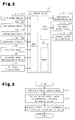
- a procedure of the feedback control carried out on the actuators of the intake system will hereafter be explained with reference to Fig. 3 .
- the procedure is performed by the control section 41 at predetermined control cycles.
- the target control values of the actuators which changes the condition of the intake air, which includes the intake flow rate, the recirculated exhaust flow rate, and the boost pressure is changed, are calculated (step S10).
- a target opening degree of each air intake throttle valve 51L, 51R is obtained in correspondence with the accelerator pedal depression degree and the engine speed. If the intake flow rate falls excessively short with respect to the fuel injection amount, the fuel burns incompletely and the particulate matter in the exhaust gas increases. In contrast, if the opening degree of each air intake throttle valve 51L, 51R is increased to raise the intake flow rate, the negative pressure decreases, which makes it difficult to accomplish exhaust gas recirculation suitable for the engine operating state.
- the target opening degree of the air intake throttle valve 51L, 51R is set in such a range that the amount of the particulate matter in the exhaust gas is negligible and a negative pressure ensuring optimal exhaust gas recirculation is maintained.
- the thus set target control value is common for the air intake throttle valves 51L, 51R. That is, operation of the air intake throttle valve 51L and that of the air intake throttle valve 51R are controlled in accordance with the common target control value.
- a target opening degree of each exhaust flow rate adjusting valve 52L, 52R is calculated in correspondence with the accelerator pedal depression degree, the engine speed, the boost pressure, and the intake flow rate, in such a manner that the exhaust gas is recirculated by an amount optimal for the engine operating state.
- the obtained target opening degree is common for the exhaust flow rate adjusting valves 52L, 52R.
- operation of the exhaust flow rate adjusting valve 52L and that of the exhaust flow rate adjusting valve 52R are controlled in accordance with the common target control value.
- a target nozzle opening degree of each boost pressure changing mechanism 50L, 50R is calculated in correspondence with the accelerator pedal depression degree, the engine speed, and the boost pressure in such a manner that a boost pressure optimal for the engine operating state is obtained.
- the determined target nozzle opening degree is common for the boost pressure changing mechanisms 50L, 50R. That is, operation of the boost pressure changing mechanism 50L and that of the boost pressure changing mechanism 50R are controlled in accordance with the common target control value.
- the intake flow rate sensors 31L, 31R are arranged in the corresponding inlet lines 13L, 13R. This provides two values obtained by the intake flow rate sensors 31L, 31R as detection values of the intake flow rate. As has been described, the flow passage areas and lengths of the inlet lines 13L, 13R are substantially equal. Thus, basically, there is no significant difference between the two detection values. However, since explosion takes place intermittently in each of the cylinders, the rotation speed of the rotor 27 of the corresponding supercharger 24L, 24R actually fluctuates. This causes pulsation of the intake air in such a manner that the detection values of the intake flow rate become different from each other.
- the detection values are first smoothed using the following expressions (1) and (2). Then, the average value QA of the smoothed values is determined using the expression (3). For example, in calculation of the target opening degree of each exhaust flow rate adjusting valve 52L, 52R in correspondence with the intake flow rate, the obtained average value QA is used as a value of the intake flow rate.
- "Q1" represents a detection value obtained by the intake flow rate sensor 31L
- “Q2” represents a detection value provided by the intake flow rate sensor 31R.
- the suffixes "(i)” and “(i - 1)” represent a detection value of a current control cycle and a detection value of a previous control cycle, respectively.
- "n” is a constant (an integer not less than "1"), in accordance with which the level of smoothing is determined. The greater the constant n, the more smoothed change of the detection value caused by the pulsation of the intake air becomes. However, if the constant n is excessively great, responsiveness of the detection values lowers with respect to change of the intake flow rate in a transient operating state. Thus, the constant n is determined considering the responsiveness of the detection values and the extent of the pulsation of the intake air comprehensively.
- the target control value of each actuator is calculated in this manner, the target control value is corrected to compensate the difference between the actuators (step S11). Specifically, such correction is carried out using the following expressions (4) and (5). ⁇ t ⁇ 1 ⁇ ⁇ t + K ⁇ 1 ⁇ ⁇ ⁇ 1 ⁇ t ⁇ 2 ⁇ ⁇ t + K ⁇ 2 ⁇ ⁇ ⁇ 2
- the values "K1” and "K2" are constants. The target opening degree ⁇ t1 of the air intake throttle valve 51L and the target opening degree ⁇ t2 of the air intake throttle valve 51R are set through such correction.
- the goal of such correction is to compensate the difference between the air intake throttle valves 51L, 51R, but not to change the target opening degree of each air intake throttle valve 51L, 51R. In other words, the correction does not regulate the opening degrees of the air intake throttle valves 51L, 51R to different values.
- the description so far has focused on the correction of the target opening degree of each air intake throttle valve 51L, 51R by way of example, the target opening degree of each exhaust flow rate adjusting valve 52L, 52R and the target nozzle opening degree of each boost pressure changing mechanism 50L, 50R are corrected in the same manner.
- the control section 41 After the correction is performed to compensate the difference between the actuators, the control section 41 performs feedback control on the actuators in such a manner that the target control values match the corresponding actual values detected by the sensors (step S12).
- the condition of the intake air such as the intake flow rate, the amount of recirculated exhaust gas, and the boost pressure is controlled in correspondence with the engine operating state.
- the first embodiment has the following advantages.
- the exhaust flow rate adjusting valves 52L, 52R, the boost pressure changing mechanisms 50L, 50R, and the air intake throttle valves 51L, 51R are feedback controlled in such a manner as to adjust the amount of recirculated exhaust gas, the boost pressure, and the intake flow rate to suitable values in correspondence with the engine operating state.
- the feedback control is continuously carried out, the following problem may occur.
- the opening degree of one of the exhaust flow rate adjusting valves 52L, 52R becomes unchangeable, the opening degree of the other, or the normally functioning one, of the exhaust flow rate adjusting valves 52L, 52R may become excessively great. In this case, a great amount of recirculated exhaust gas is introduced into the corresponding one of the branch lines 15L, 15R. This causes a great difference in the concentration of the recirculated exhaust gas between the intake air supplied to the bank 11L and the intake air fed to the bank 11R.
- control section 41 performs failsafe control for a case in which a malfunction occurs in any one of the exhaust flow rate adjusting valves 52L, 52R, the boost pressure changing mechanisms 50L, 50R, and the air intake throttle valves 51L, 51R, in addition to the above-described feedback control.
- the failsafe control it is determined whether a malfunction has occurred in the exhaust flow rate adjusting valves 52L, 52R. Specifically, if at least one of the following conditions (1) and (2) is met, it is determined that at least one of the exhaust flow rate adjusting valves 52L, 52R is malfunctioning.
- the feedback control on the exhaust flow rate adjusting valves 52L, 52R is suspended and the target opening degree of the exhaust flow rate adjusting valves 52L, 52R is set to the minimum value. This fully closes the normally functioning one of the exhaust flow rate adjusting valves 52L, 52R. In this manner, when only one of the flow rate adjusting valves 52L, 52R is subjected to the feedback control, the opening degree of the one of the exhaust flow rate adjusting valves 52L, 52R is prevented from becoming excessively great due to the feedback control.
- this failsafe control it is first determined whether there is a malfunction in the boost pressure changing mechanisms 50L, 50R. Specifically, if at least one of the following conditions (1) and (2) is met, it is determined that at least one of the boost pressure changing mechanisms 50L, 50R is malfunctioning.
- the amount of the intake air flowing in the inlet line 13L becomes different from the amount of the intake air flowing in the inlet line 13R.
- Such difference is monitored in accordance with the condition (2) in the above-described determination of a malfunction.
- the condition (2) is not satisfied if, for example, a foreign object is caught by the wall of the nozzle opening of either or each of the boost pressure changing mechanisms 50L, 50R and hampers normal supercharging, despite the fact that the nozzles of the boost pressure changing mechanisms 50L, 50R are normally operating. It is thus determined that there is a malfunction.
- the feedback control on the boost pressure changing mechanisms 50L, 50R is stopped and the target nozzle opening degree of the boost pressure changing mechanisms 50L, 50R is set to the maximum value.
- the supercharging efficiency of the normally functioning one of the boost pressure changing mechanisms 50L, 50R becomes minimum. Accordingly, when only one of the boost pressure changing mechanisms 50L, 50R is subjected to the feedback control, the one of the boost pressure changing mechanisms 50L, 50R is prevented from receiving an excessive load. Thus, excessive rotation of the rotors 27 and damages to the superchargers 24L, 24R are prevented.
- the failsafe control it is first determined whether there is a malfunction in the air intake throttle valves 51L, 51R. Specifically, if at least one of the following conditions (1) and (2) is satisfied, it is determined that at least one of the air intake throttle valves 51L, 51R is malfunctioning.
- the amount of the intake air flowing in the inlet line 13L becomes different from the amount of the intake air flowing in the inlet line 13R.
- Such difference is monitored in correspondence with the condition (2) in the above-described determination of a malfunction.
- the condition (2) is not met if a foreign object is caught by the wall of the opening of either or each of the air intake throttle valves 51L, 51R and hampers normal recirculation of exhaust gas, despite the fact that the air intake throttle valves 51L, 51R are operating. It is thus determined that there is a malfunction.
- the feedback control on the air intake throttle valves 51L, 51R is suspended and the target opening degree of the air intake throttle valves 51L, 51R is set to the maximum value.
- the normally functioning one of the air intake throttle valves 51L, 51R becomes fully open. A sufficient amount of intake air is thus supplied to the engine 10. This prevents incomplete combustion and a resulting increase of particulate matter in the exhaust gas.
- the exhaust flow rate adjusting valves 52L, 52R are fully closed in addition to the above-described procedures. This stops recirculation of exhaust gas by the external exhaust gas recirculating mechanisms. In this manner, shortage of the intake flow rate is further effectively suppressed. Also, the amounts of recirculated exhaust gas fed into the branch lines 15L, 15R is prevented from becoming different from one branch line to the other. This prevents the concentrations of recirculated exhaust gas in the intake air fed to the banks 11L, 11R from becoming greatly different from one bank to the other.
- the failsafe control procedures to deal with malfunctions in the boost pressure changing mechanisms 50L, 50R, the air intake throttle valves 51L, 51R, and the exhaust flow rate adjusting valves 52L, 52R are performed. However, at least one of these failsafe control procedures to deal with a malfunction of the corresponding actuators may be carried out.
- the actual values Prior to averaging the actual values of the intake flow rate, the actual values are subjected to the smoothing procedure. However, as long as pulsation of the intake air in the inlet lines 13L, 13R is negligible, the smoothing procedure may be omitted.
- filtering using various types of high-pass filters or moving average calculation may be performed other than the calculation represented by the expression (1).
- geometric average calculation for example, may be performed instead of the arithmetic average calculation represented by the expression (3).
- the boost pressure changing mechanisms 50L, 50R of the superchargers 24L, 24R each change the nozzle opening degree in correspondence with the engine operating state. This changes the flow velocity of the exhaust gas blasted against the turbine wheel, thus adjusting the boost pressure.
- the present invention is not restricted to such boost pressure changing mechanisms.
- mechanisms that change the boost pressure using the output shaft of the engine may be employed as the superchargers 24L, 24R.
- the feedback control is carried out on the actuators of the intake system, such as the air intake throttle valves 51L, 51R, the boost pressure changing mechanisms 50L, 50R, and the boost pressure mechanisms, by way of example.
- the actuators may be open-controlled.
- actuators of the illustrated embodiments use the motors as the drive sources, other drive sources such as pneumatic pressure or hydraulic pressure may be used.
- the engine 10 has the two superchargers 24L, 24R in correspondence with the banks 11L, 11R. However, the engine 10 may include one supercharger corresponding to only one of the banks 11L, 11R.
- Intake air temperature sensors may be provided in correspondence with the inlet lines 13L, 13R as additional sensors that detect the condition of the intake air. Detection values of the intake air temperature are subjected to calculation similar to the calculation performed on the detection values of the intake flow rate. The detection values are thus used in various types of control performed on the intake system.
- the nozzle opening degree of the other one of the boost pressure changing mechanisms 50L, 50R is changed to a fully open level to prohibit supercharging of the intake air.
- the target value of the boost pressure may be set to a value lower than normal, for example, in such a manner as to restrict, not completely prohibit, the supercharging.
- the target value of the amount of the recirculated exhaust gas may be set to a value lower than normal, for example, in such a manner as to restrict, not completely prohibit, recirculation of exhaust gas.
- the normally functioning one of the actuators may be operated continuously, in such a manner as to adjust the intake flow rate or supercharge the intake pressure or recirculate the exhaust gas.
- an engine may include cooling devices, which are provided in both banks 11L, 11R to cool recirculated exhaust gas flowing in corresponding recirculating passages.
- the engine regulates the temperature of the recirculated exhaust gas by adjusting cooling efficiency of the cooling devices.
- operation of the cooling devices may be controlled in the same manner as the above-described manner, in which the actuators are operated.
- each of the cooling devices is an actuator that changes the condition of the intake air flowing in the intake passage.
- the converging line 16 which connects the branch lines 15L, 15R to each other, is a surge tank provided commonly for the banks 11L, 11R.
- the converging line and the surge tank may be provided separately from each other.
- the present invention may be used in a V diesel engine having six or less cylinders or ten or more cylinders, other than the eight-cylinder V diesel engine 10.
Landscapes
- Engineering & Computer Science (AREA)
- Chemical & Material Sciences (AREA)
- Combustion & Propulsion (AREA)
- Mechanical Engineering (AREA)
- General Engineering & Computer Science (AREA)
- Fluid Mechanics (AREA)
- Physics & Mathematics (AREA)
- Analytical Chemistry (AREA)
- Control Of Throttle Valves Provided In The Intake System Or In The Exhaust System (AREA)
- Output Control And Ontrol Of Special Type Engine (AREA)
- Combined Controls Of Internal Combustion Engines (AREA)
- Electrical Control Of Air Or Fuel Supplied To Internal-Combustion Engine (AREA)
- Supercharger (AREA)
Abstract
Description
- The present invention relates to an air intake control device of a V-diesel engine that controls the condition of intake air supplied to the V-diesel engine.
- Recently, the number of cylinders in diesel engines of vehicles has been increasing in accordance with demands for higher powers and larger displacement. For example, if a diesel engine has six or eight cylinders, the engine is arranged often as a V type in which the cylinders are arranged in a V shape in order to save space in the engine compartment. As shown in
Fig. 4 , anintake passage 2 of the V-engine includes a common upstream portion and branched downstream portions, which are connected to a pair ofbanks intake throttle valve 3, which adjusts the intake flow rate, is provided in the upstream portion of theintake passage 2, that is, in the common portion of thebanks banks intake throttle valve 3 at the same time. - However, if the diesel engine of this configuration has a great displacement, the intake flow rate changes in a wide range. It is thus difficult to accurately adjust the intake flow rate over the wide range using the air intake throttle valve provided commonly for the two banks.
- For example, as shown in
Fig. 5 ,intake passages banks intake throttle valves corresponding intake passages intake throttle valves - [Patent Document 1] Japanese Laid-Open Patent Publication No.
2004-124778 - However, it is extremely difficult to equalize the lengths, shapes, or ambient temperatures of the
intake passages banks intake throttle valves intake passages intake throttle valve - Although the description so far discusses the problem of the air intake throttle valves by way of example, the problem is generally common in other actuators that change the condition of intake air flowing in an intake passage of a V-diesel engine, such as an exhaust flow rate adjusting valve of an external exhaust gas recirculating mechanism, which adjusts the amount of exhaust gas recirculated from an exhaust passage to an intake passage, or a boost pressure changing mechanism, which changes boost pressure of a supercharger.
- Accordingly, it is an objective of the present invention to provide an air intake control device of a V-diesel engine that accurately changes the condition of intake air by a pair of actuators provided in an intake passage and suppresses increase of load of calculation without complicating the configuration involved in control of operation of the actuators.
- To achieve the foregoing objective an air intake control device of a V diesel engine having an intake passage through which intake air is supplied to respective cylinders formed in a pair of banks of the V diesel engine, an actuator that changes the condition of the intake air flowing in the intake passage, and control means that controls operation of the actuator is provided. The intake passage includes a pair of connecting portions each connected to one of the banks, a converging portion that connects the connecting portions together, and a pair of branch portions branched from the converging portion and extending upstream. The actuator is provided in correspondence with each of the branch portions. The control means controls operation of each of the actuators in accordance with a common target control value.
- In this structure, the actuators are arranged in correspondence with the branch portions of the intake passage. Thus, compared to a case in which an actuator provided commonly for the two banks changes the condition of the intake flow rate, the operable range of each actuator becomes small. This allows each actuator to accurately change the condition of the intake flow rate. After the condition of the intake air is changed by the actuators, the intake air is temporarily mixed together in the converging portion of the intake passage. The intake air is then distributed to the banks through the corresponding connecting portions. This makes it unnecessary to control operation of the actuators separately. In other words, operation of the actuators is controlled in accordance with the common target control value. This prevents the structures involved in control of operation of the actuators from becoming complicated and load of calculation from increasing. The condition of the intake air includes, for example, the flow rate, pressure, and temperature of the intake flow rate , and the concentration and temperature of the recirculated exhaust gas in the intake air.
- The above described air intake control device of the V diesel engine preferably has a sensor that detects the condition of the intake air flowing in the intake passage. The sensor is preferably provided in correspondence with each of the branch portions.
- In this structure, the sensors are provided in correspondence with the branch portions of the intake passage. Thus, compared to a case in which a sensor provided commonly for the banks detects the condition of the intake flow rate, the detectable range of each of the sensors becomes small. This allows each sensor to accurately detect the condition of the intake air.
- In the above described air intake control device of the V diesel engine, the sensor preferably includes a pair of intake flow rate sensors each arranged in one of the branch portions. The control means preferably calculates the amount of the intake air flowing in the intake passage by averaging detection values provided by the intake flow rate sensors.
- In this structure, even if pulsation occurs in the intake air flowing in the branch portions and thus the detection values detected by the intake flow rate sensors become different from each other, the calculated value of the intake flow rate is prevented from being altered. Further, the amount of the intake air introduced from the branch portions to the cylinders through the converging portion and the corresponding connecting portions is accurately determined.
- In the above described air intake control device of the V diesel engine, the control means preferably performs a smoothing procedure on the detection values of the intake flow rate sensors prior to the averaging procedure.
- This configuration further effectively suppresses influence by the pulsation of the intake air.
- In the above described air intake control device of the V diesel engine, the control means preferably feedback controls operation of the actuators in accordance with the target control value. The control means preferably further includes determining means that determines whether there is a malfunction in the actuators, and restricting means that restricts change of the condition of the intake air through a feedback control performed on one of the actuators if the determining means determines that the other one of the actuators is malfunctioning.
- In this structure, if it is determined that one of the actuators is malfunctioning, adjustment of the condition of the intake air by the other one of the actuators is restricted. Excessive load acting on the functioning actuator is thus suppressed. This also prevents the banks from receiving the intake air of the condition different from one bank to the other, which is caused if the functioning one of the actuators solely changes of the condition of the intake air. Further, restriction of the change of the condition of the intake air includes prohibition of the change of the condition of the intake air through feedback control on one of the actuators if a malfunction of the other one of the actuators is detected.
- In the above described air intake control device of the V diesel engine, the V diesel engine preferably further includes a pair of superchargers arranged in correspondence with the branch portions, and a pair of boost pressure changing mechanisms each changing a boost pressure of the corresponding supercharger. The boost pressure changing mechanisms serve as the actuators.
- In the above described air intake control device of the V diesel engine, the restricting means preferably minimizes a supercharging efficiency by prohibiting the feedback control on the other one of the boost pressure changing mechanisms if the determining means determines that one of the boost pressure changing mechanisms is malfunctioning.
- In this structure, if one of the boost pressure changing mechanisms is malfunctioning, the supercharger is prevented from receiving an excessive load due to the feedback control performed by the control means on the other one of the boost pressure changing mechanism.
- The above described air intake control device of the V diesel engine preferably includes a pair of exhaust flow rate adjusting valves serving as the actuators. The exhaust flow rate adjusting valves are formed in a pair of communication lines each connecting an exhaust passage connected to the cylinders and the corresponding one of the branch portions to each other. The exhaust flow rate adjusting valves each adjust an amount of exhaust gas recirculated to the corresponding branch portions through the associated communication passage. If the determining means determines that one of the exhaust flow rate adjusting valves is malfunctioning, the restricting means fully closes the other one of the exhaust flow rate adjusting valves by prohibiting the feedback control on the exhaust flow rate adjusting valve.
- In this structure, if one of the exhaust flow rate adjusting valves of the external exhaust gas recirculating mechanism is malfunctioning, the opening degree of the other one of the exhaust flow rate adjusting valves is prevented from being excessively increased due to the feedback control of such opening degree by the control means. This suppresses introduction of a great amount of recirculated exhaust gas into the branch portion corresponding to the functioning exhaust flow rate adjusting valve. Thus, the banks are prevented from receiving the intake air containing recirculated gas of a concentration greatly different from one bank to the other.
- The above described air intake control device of the V diesel engine preferably includes a pair of air intake throttle valves serving as the actuators. The air intake throttle valves are formed in the corresponding branch portions. The air intake throttle valves each adjust the amount of the intake air passing through the corresponding branch portion. If the determining means determines that one of the air intake throttle valves is malfunctioning, the control means fully opens the other one of the air intake throttle valves by prohibiting the feedback control on the air intake throttle valve.
- In this structure, even if one of the intake air throttle valves is malfunctioning, a maximum amount of intake air is reliably supplied to each of the banks by fully opening the other one of the intake air throttle valves. This suppresses increase of particulate matter in the exhaust gas caused by incomplete combustion.
- In the above described air intake control device of the V diesel engine, the converging portion is preferably formed by a surge tank provided commonly for the banks.
- By increasing the cross-sectional area of the surge tank in the intake passage compared to those of the remaining portions of the intake passage, the intake air reliably has a volume necessary for reducing pulsation of intake air. Thus, by using the surge tank provided commonly for the banks as the converging portion, the intake air flowing from the two branch portions into the converging portion is effectively mixed together. The amounts and properties of the intake air sent from the converging portion to the two connecting portions thus become equal. This reduces undesirable influence caused by differences of the amounts and properties of the intake air fed to the cylinders from one bank to the other, such as variation of the engine operating speed and aggravation of the exhaust properties. Further, compared to a case in which surge tanks are provided separately in correspondence with the respective banks, this structure is suitable for large intake air control devices.
-
-
Fig. 1 is a view schematically showing the configuration of an engine and an air intake control device of the engine according to an embodiment of the present invention; -
Fig. 2 is a block diagram representing the configuration of a control section of the air intake control device, that of a sensor, and that of an actuator; -
Fig. 3 is a flowchart representing a procedure for performing feedback control on the actuator; -
Fig. 4 is a view schematically showing the configuration of a conventional air intake control device of a V-diesel engine; and -
Fig. 5 is a view schematically showing the configuration of another conventional air intake control device of a V-diesel engine. - An air intake control device of an eight-cylinder V-diesel engine according to a first embodiment of the present invention will now be described with reference to
Figs. 1 and2 . - As shown in
Fig. 1 , anengine 10 is a V-engine, in which a pair ofbanks banks engine 10 includes anair cleaner 12, a pair ofintercoolers throttle body 20, andsuperchargers banks superchargers supercharger rotor 27. Acompressor blade 26 and aturbine blade 25 are arranged at ends of each of therotors 27. Each of thecompressor blades 26 is arranged in the corresponding one of a pair ofinlet lines corresponding intercoolers air cleaner 12. Each of theturbine blades 25 is provided in the corresponding one of a pair ofexhaust passages banks - Each
supercharger exhaust passage rotor 27 is rotated by the exhaust gas in thecorresponding exhaust passage turbine blade 25. This causes thecorresponding compressor blade 26 to pressurize the intake air in thecorresponding inlet line corresponding intercooler compressor blades 26 are located substantially at the same positions in theinlet lines - Each
supercharger pressure changing mechanism pressure changing mechanisms turbine blades 25 and a motor (not shown) that changes the opening degree of the nozzle. Each boostpressure changing mechanism turbine blade 25. Thus, as the flow velocity of the exhaust gas changes in correspondence with the engine operating state, the boost pressure changes. If theengine 10 is operated in a low load and low rotation range, the flow velocity of the exhaust gas is small and the rotational speed of eachrotor 27 is low. The boost pressure thus becomes low. Contrastingly, if theengine 10 is operated in a high load and high rotation range, the flow velocity of the exhaust gas is great and the rotational speed of eachrotor 27 is high. The boost pressure thus becomes high. - Thus, when the increase of the boost pressure and the improvement of supercharging response in the low load and low rotation range are required, each boost
pressure changing mechanism turbine blade 25. This increases the boost pressure and improves supercharging response. Contrastingly, when theengine 10 is operated in the high load and high rotation range, the boostpressure changing mechanism turbine blade 25. This suppresses excessive rotation of therotor 27 and excessive rise of boost pressure. - The intake air supercharged by each
supercharger corresponding intercooler inlet line intercooler supercharger throttle body 20. The twosuperchargers pressure changing mechanisms intercoolers - The
throttle body 20 has a pair ofbranch lines intake throttle valves corresponding branch lines line 16, which is downstream from thebranch lines intercoolers throttle body 20, the intake air is distributed to thebranch lines line 16 through the airintake throttle valves line 16 functions as a surge tank provided commonly for thebanks line 16 is greater than the cross-sectional area of eachbranch line line 16 ensures a volume necessary for decreasing pulsation of the intake air. - Thus, even if there are differences in the temperature, the pressure, and the state of pulsation between the intake air flowing from the air
intake throttle valve 51L into the convergingline 16 and the intake air flowing from the airintake throttle valve 51R into the convergingline 16, such differences between the condition of the intake air from the airintake throttle valve 51L and the condition of the intake air from the airintake throttle valve 51R are eliminated by temporarily mixing the intake air together in the convergingline 16. That is, the intake air is mixed substantially homogeneously. Thebranch lines intake throttle valves branch lines intake throttle valves intake throttle valves - In the first embodiment, with reference to
Fig. 1 , a communicating portion S, which connects thebranch lines throttle body 20 at a position upstream from thebranch lines intercoolers branch lines branch lines line 16 operates to eliminate the differences in the condition between the intake air flowing into thebranch line 15L and the intake air flowing into thebranch line 15R. In the first embodiment, the convergingline 16 operates to mix the intake air from thebranch line 15L with the intake air from thebranch line 15R, thus eliminating the differences in the condition between the intake air from thebranch line 15L and the intake air from thebranch line 15R. Mixing of the intake air in the communicating portion S is thus performed as an auxiliary operation. - A pair of distributing
lines line 16. The downstream side of one of the distributinglines left bank 11L, as viewed inFig. 1 , and connected to the cylinders of thebank 11L. The downstream side of the other of the distributinglines right bank 11R, as viewed inFig. 1 . Thebranch lines line 16, the intake air is introduced into thebranch lines branch lines corresponding banks - The intake system of the
engine 10 includes an external exhaust gas recirculating mechanism, which recirculates some of the exhaust gas from theexhaust passages branch lines recirculating lines rate adjusting valves corresponding recirculating lines recirculating line 17L connects theexhaust passage 21L upstream from thesupercharger 24L and thebranch line 15L downstream from the airintake throttle valve 51L to each other. Therecirculating line 17R connects theexhaust passage 21R upstream from thesupercharger 24R and thebranch line 15R downstream from the airintake throttle valve 51R to each other. The exhaust flowrate adjusting valve 52L is provided at the most downstream position in therecirculating line 17L, which is the connecting portion between therecirculating line 17L and thebranch line 15L. The exhaust flowrate adjusting valve 52R is provided at the most downstream position in therecirculating line 17R, which is the connecting portion between therecirculating line 17R and thebranch line 15R. - The external exhaust gas recirculating mechanism operates to return some of the exhaust gas from each
exhaust passage corresponding branch line recirculating line intake throttle valve branch line rate adjusting valves rate adjusting valve exhaust passage branch line - Like the exhaust flow
rate adjusting valves intake throttle valves intake throttle valve branch line line 16, or the total amount of the intake air distributed from the convergingline 16 to the cylinders through the distributingline - In the
diesel engine 10, the amount of the intake air regulated by each airintake throttle valve intake throttle valve - The opening degree of each air
intake throttle valve rate adjusting valve intake throttle valve intake throttle valve exhaust passage branch line intake throttle valve intake throttle valve rate adjusting valve intake throttle valve rate adjusting valve - As illustrated in
Fig. 2 , theengine 10 has acontrol section 41, which performs various procedures of the air intake control device. Theengine 10 also hassensors control section 41, andactuators control section 41. Thecontrol section 41 has amemory 44, aninput circuit 42, and adriver circuit 43. Thememory 44 stores data necessary for the procedures. Theinput circuit 42 receives detection signals from the sensors and converts the detection signals from analog signals to digital signals as needed. Thedriver circuit 43 drives the actuators. In the first embodiment, the actuators include the airintake throttle valves rate adjusting valves pressure changing mechanisms -
Opening degree sensors intake throttle valves intake throttle valves Opening degree sensors rate adjusting valves rate adjusting valves Opening degree sensors pressure changing mechanisms flow rate sensors corresponding inlet lines superchargers inlet lines engine 10 also includes anengine speed sensor 35 detecting the engine speed, an accelerator pedaldepression degree sensor 36 detecting the opening degree of the accelerator, and an airintake pressure sensor 37 detecting the air intake pressure (the boost pressure) in the convergingline 16. - The sensors are electrically connected to the
input circuit 42 of thecontrol section 41. Thecontrol section 41 receives detection signals from the sensors through theinput circuit 42. In correspondence with the detection signals of the sensors, thecontrol section 41 sets target control values for the actuators of the intake system, such as the airintake throttle valves rate adjusting valves pressure changing mechanisms control section 41 performs feedback control on the actuators with reference to the set target control values. - A procedure of the feedback control carried out on the actuators of the intake system will hereafter be explained with reference to
Fig. 3 . The procedure is performed by thecontrol section 41 at predetermined control cycles. - As illustrated in
Fig. 3 , the target control values of the actuators, which changes the condition of the intake air, which includes the intake flow rate, the recirculated exhaust flow rate, and the boost pressure is changed, are calculated (step S10). - Specifically, a target opening degree of each air
intake throttle valve intake throttle valve intake throttle valve intake throttle valves intake throttle valve 51L and that of the airintake throttle valve 51R are controlled in accordance with the common target control value. - A target opening degree of each exhaust flow
rate adjusting valve rate adjusting valves rate adjusting valve 52L and that of the exhaust flowrate adjusting valve 52R are controlled in accordance with the common target control value. A target nozzle opening degree of each boostpressure changing mechanism pressure changing mechanisms pressure changing mechanism 50L and that of the boostpressure changing mechanism 50R are controlled in accordance with the common target control value. - The intake
flow rate sensors corresponding inlet lines flow rate sensors inlet lines rotor 27 of thecorresponding supercharger - To solve this problem, in the first embodiment, the detection values are first smoothed using the following expressions (1) and (2). Then, the average value QA of the smoothed values is determined using the expression (3). For example, in calculation of the target opening degree of each exhaust flow
rate adjusting valve 


- In the expressions (1) and (2), "Q1" represents a detection value obtained by the intake
flow rate sensor 31L, and "Q2" represents a detection value provided by the intakeflow rate sensor 31R. The suffixes "(i)" and "(i - 1)" represent a detection value of a current control cycle and a detection value of a previous control cycle, respectively. "n" is a constant (an integer not less than "1"), in accordance with which the level of smoothing is determined. The greater the constant n, the more smoothed change of the detection value caused by the pulsation of the intake air becomes. However, if the constant n is excessively great, responsiveness of the detection values lowers with respect to change of the intake flow rate in a transient operating state. Thus, the constant n is determined considering the responsiveness of the detection values and the extent of the pulsation of the intake air comprehensively. - After the target control value of each actuator is calculated in this manner, the target control value is corrected to compensate the difference between the actuators (step S11). Specifically, such correction is carried out using the following expressions (4) and (5).


- In the expressions (4) and (5), "Δα1" represents the constant difference (= θt - θa) between the actual opening degree θa and the target opening degree θt of the air
intake throttle valves intake throttle valves intake throttle valve 51L and the target opening degree θt2 of the airintake throttle valve 51R are set through such correction. The goal of such correction is to compensate the difference between the airintake throttle valves intake throttle valve intake throttle valves intake throttle valve rate adjusting valve pressure changing mechanism - After the correction is performed to compensate the difference between the actuators, the
control section 41 performs feedback control on the actuators in such a manner that the target control values match the corresponding actual values detected by the sensors (step S12). This gradually changes the opening degree of each of the airintake throttle valves rate adjusting valves pressure changing mechanisms - The first embodiment has the following advantages.
- (1) The actuators such as the air
intake throttle valves rate adjusting valves pressure changing mechanisms superchargers line 16 in the intake passage, or in correspondence with theinlet lines branch lines banks line 16 and then distributed to thebanks lines - (2) Particularly, the intake
flow rate sensors corresponding inlet lines banks flow rate sensor flow rate sensors - (3) The intake flow rate is obtained by averaging the detection values of the intake
flow rate sensors branch lines branch line line 16 and the associated distributingline - (4) The detection values are subjected to a smoothing procedure prior to averaging of the detection values of the intake flow rate. This further effectively suppresses influence by pulsation of the intake air.
- (5) The converging
line 16, which connects thebranch lines banks line 16. The intake air introduced from thebranch lines line 16 is thus further effectively mixed together. The amounts and the properties of the intake air flowing from the convergingline 16 to the distributinglines banks banks - A second embodiment of the present invention will hereafter be explained. In the first embodiment, the exhaust flow
rate adjusting valves pressure changing mechanisms intake throttle valves rate adjusting valves - Specifically, if the opening degree of one of the exhaust flow
rate adjusting valves rate adjusting valves branch lines bank 11L and the intake air fed to thebank 11R. Further, if one of the boostpressure changing mechanisms rotor 27 occurs in the other, or the normally functioning one, of the boostpressure changing mechanisms rotor 27, which causes excessive load acting on the associated supercharger. Also, if one of the airintake throttle valves - To solve this problem, in the second embodiment, the
control section 41 performs failsafe control for a case in which a malfunction occurs in any one of the exhaust flowrate adjusting valves pressure changing mechanisms intake throttle valves - In the failsafe control, it is determined whether a malfunction has occurred in the exhaust flow
rate adjusting valves rate adjusting valves - (1) The difference between the target opening degree of the exhaust flow
rate adjusting valves opening degree sensors - (2) The difference between the two intake flow rates detected by the intake
flow rate sensors - If one of the exhaust flow
rate adjusting valves branch lines inlet line 13L and the amount of the intake air flowing in theinlet line 13R. Such difference is monitored in accordance with the condition (2) through the above-described determination of a malfunction. The condition (2) cannot be satisfied if, for example, a foreign object is caught by the wall of the opening of either or each of the exhaust flowrate adjusting valves rate adjusting valves - If it is determined that at least one of the exhaust flow
rate adjusting valves rate adjusting valves rate adjusting valves rate adjusting valves rate adjusting valves rate adjusting valves branch lines bank 11L and the intake air fed to thebank 11R. - In this failsafe control, it is first determined whether there is a malfunction in the boost
pressure changing mechanisms pressure changing mechanisms - (1) The difference between the target nozzle opening degree of the boost
pressure changing mechanisms opening degree sensors - (2) The difference between the two intake flow rates detected by the intake
flow rate sensors - If one of the boost
pressure changing mechanisms inlet line 13L becomes different from the amount of the intake air flowing in theinlet line 13R. Such difference is monitored in accordance with the condition (2) in the above-described determination of a malfunction. The condition (2) is not satisfied if, for example, a foreign object is caught by the wall of the nozzle opening of either or each of the boostpressure changing mechanisms pressure changing mechanisms - If it is determined that at least one of the boost
pressure changing mechanisms pressure changing mechanisms pressure changing mechanisms pressure changing mechanisms pressure changing mechanisms pressure changing mechanisms rotors 27 and damages to thesuperchargers - In the failsafe control, it is first determined whether there is a malfunction in the air
intake throttle valves intake throttle valves - (1) The difference between the target opening degree of the air
intake throttle valves opening degree sensors - (2) The difference between the two detection values obtained by the intake
flow rate sensors - If one of the air
intake throttle valves inlet line 13L becomes different from the amount of the intake air flowing in theinlet line 13R. Such difference is monitored in correspondence with the condition (2) in the above-described determination of a malfunction. The condition (2) is not met if a foreign object is caught by the wall of the opening of either or each of the airintake throttle valves intake throttle valves - If it is determined that at least one of the air
intake throttle valves intake throttle valves intake throttle valves intake throttle valves engine 10. This prevents incomplete combustion and a resulting increase of particulate matter in the exhaust gas. - If a malfunction occurs in the air
intake throttle valves rate adjusting valves branch lines banks - The illustrated embodiments may be modified in the following manners.
- In the second embodiment, if one of the two above-described conditions (1) and (2) is satisfied, it is determined that there is a malfunction in the boost
pressure changing mechanisms intake throttle valves rate adjusting valves - In the second embodiment, the failsafe control procedures to deal with malfunctions in the boost
pressure changing mechanisms intake throttle valves rate adjusting valves - Prior to averaging the actual values of the intake flow rate, the actual values are subjected to the smoothing procedure. However, as long as pulsation of the intake air in the
inlet lines - The boost
pressure changing mechanisms superchargers superchargers - In the description so far, the feedback control is carried out on the actuators of the intake system, such as the air
intake throttle valves pressure changing mechanisms - Although the actuators of the illustrated embodiments use the motors as the drive sources, other drive sources such as pneumatic pressure or hydraulic pressure may be used.
- The
engine 10 has the twosuperchargers banks engine 10 may include one supercharger corresponding to only one of thebanks - Intake air temperature sensors may be provided in correspondence with the
inlet lines - If a malfunction is detected in one of the boost
pressure changing mechanisms pressure changing mechanisms pressure changing mechanisms intake throttle valves rate adjusting valves - For example, an engine may include cooling devices, which are provided in both
banks - The converging
line 16, which connects thebranch lines banks - The present invention may be used in a V diesel engine having six or less cylinders or ten or more cylinders, other than the eight-cylinder
V diesel engine 10.
Claims (10)
- An air intake control device of a V diesel engine having an intake passage through which intake air is supplied to respective cylinders formed in a pair of banks of the V diesel engine, an actuator that changes the condition of the intake air flowing in the intake passage, and control means that controls operation of the actuator,
the air intake control device being characterized in that the intake passage includes a pair of connecting portions each connected to one of the banks, a converging portion that connects the connecting portions together, and a pair of branch portions branched from the converging portion and extending upstream, wherein the actuator is provided in correspondence with each of the branch portions, and wherein the control means controls operation of each of the actuators in accordance with a common target control value. - The air intake control device of the V diesel engine according to claim 1, characterized by a sensor that detects the condition of the intake air flowing in the intake passage, the sensor being provided in correspondence with each of the branch portions.
- The air intake control device of the V diesel engine according to claim 2, characterized in that the sensor includes a pair of intake flow rate sensors each arranged in one of the branch portions,
wherein the control means calculates the amount of the intake air flowing in the intake passage by averaging detection values provided by the intake flow rate sensors. - The air intake control device of the V diesel engine according to claim 3, characterized in that the control means performs a smoothing procedure on the detection values of the intake flow rate sensors prior to the averaging procedure.
- The air intake control device of the V diesel engine according to any one of claims 1 to 4, characterized in that the control means feedback controls operation of the actuators in accordance with the target control value, the control means further including:determining means that determines whether there is a malfunction in the actuators; andrestricting means that restricts change of the condition of the intake air through a feedback control performed on one of the actuators if the determining means determines that the other one of the actuators is malfunctioning.
- The air intake control device of the V diesel engine according to claim 5, characterized in that the V diesel engine further includes a pair of superchargers arranged in correspondence with the branch portions, and a pair of boost pressure changing mechanisms each changing a boost pressure of the corresponding supercharger, the boost pressure changing mechanisms serving as the actuators.
- The air intake control device of the V diesel engine according to claim 6, characterized in that, if the determining means determines that one of the boost pressure changing mechanisms is malfunctioning, the restricting means minimizes a supercharging efficiency by prohibiting the feedback control on the other one of the boost pressure changing mechanisms.
- The air intake control device of the V diesel engine according to claim 5, characterized by a pair of exhaust flow rate adjusting valves serving as the actuators, the exhaust flow rate adjusting valves being formed in a pair of communication lines each connecting an exhaust passage connected to the cylinders and the corresponding one of the branch portions to each other, the exhaust flow rate adjusting valves each adjusting an amount of exhaust gas recirculated to the corresponding branch portions through the associated communication passage,
wherein, if the determining means determines that one of the exhaust flow rate adjusting valves is malfunctioning, the restricting means fully closes the other one of the exhaust flow rate adjusting valves by prohibiting the feedback control on the exhaust flow rate adjusting valve. - The air intake control device of the V diesel engine according to claim 5, characterized by a pair of air intake throttle valves serving as the actuators, the air intake throttle valves being formed in the corresponding branch portions, the air intake throttle valves each adjusting the amount of the intake air passing through the corresponding branch portion, and
wherein, if the determining means determines that one of the air intake throttle valves is malfunctioning, the control means fully opens the other one of the air intake throttle valves by prohibiting the feedback control on the air intake throttle valve. - The air intake control device of the V diesel engine according to any one of claims 1 to 9, characterized in that the converging portion is formed by a surge tank provided commonly for the banks.
Applications Claiming Priority (2)
| Application Number | Priority Date | Filing Date | Title |
|---|---|---|---|
| JP2006031095A JP4327805B2 (en) | 2006-02-08 | 2006-02-08 | Intake control device for V-type diesel engine |
| PCT/JP2007/051986 WO2007091542A1 (en) | 2006-02-08 | 2007-02-06 | Air intake control device of v-diesel engine |
Publications (3)
| Publication Number | Publication Date |
|---|---|
| EP1983180A1 true EP1983180A1 (en) | 2008-10-22 |
| EP1983180A4 EP1983180A4 (en) | 2017-06-28 |
| EP1983180B1 EP1983180B1 (en) | 2019-03-27 |
Family
ID=38345139
Family Applications (1)
| Application Number | Title | Priority Date | Filing Date |
|---|---|---|---|
| EP07713829.5A Ceased EP1983180B1 (en) | 2006-02-08 | 2007-02-06 | Air intake control device of v-diesel engine |
Country Status (5)
| Country | Link |
|---|---|
| US (1) | US7953540B2 (en) |
| EP (1) | EP1983180B1 (en) |
| JP (1) | JP4327805B2 (en) |
| CN (1) | CN101379280B (en) |
| WO (1) | WO2007091542A1 (en) |
Cited By (1)
| Publication number | Priority date | Publication date | Assignee | Title |
|---|---|---|---|---|
| EP2466091A1 (en) * | 2010-12-18 | 2012-06-20 | Audi AG | Method for operating a motor vehicle with two turbochargers |
Families Citing this family (19)
| Publication number | Priority date | Publication date | Assignee | Title |
|---|---|---|---|---|
| DE102008046594A1 (en) * | 2008-07-18 | 2010-01-21 | Mahle International Gmbh | valve means |
| RU2383756C1 (en) * | 2008-08-08 | 2010-03-10 | Открытое акционерное общество холдинговая компания "Коломенский завод" | Internal combustion engine with high limiting characteristic and high rate of load acceptance |
| JP5282056B2 (en) * | 2010-02-09 | 2013-09-04 | 株式会社豊田自動織機 | Internal combustion engine |
| JP5595107B2 (en) * | 2010-04-27 | 2014-09-24 | 日野自動車株式会社 | Internal combustion engine |
| CN102943706B (en) * | 2012-10-31 | 2015-08-26 | 中国北方发动机研究所(天津) | A kind of intercooler for diesel engine |
| EP2956657B1 (en) * | 2013-02-13 | 2016-11-09 | Volkswagen Aktiengesellschaft | Internal combustion engine with booster |
| US9976474B2 (en) * | 2016-04-14 | 2018-05-22 | Caterpillar Inc. | Turbocharger speed anomaly detection |
| KR20170128785A (en) * | 2016-05-13 | 2017-11-24 | 현대자동차주식회사 | Control method of egr valve for vehicle and control system for the same |
| CN107489522A (en) * | 2016-07-21 | 2017-12-19 | 宝沃汽车(中国)有限公司 | A kind of booster vacuum tank, gas extraction system and engine |
| JP6414582B2 (en) * | 2016-11-14 | 2018-10-31 | マツダ株式会社 | ENGINE CONTROL METHOD AND CONTROL DEVICE |
| CN107228022A (en) * | 2017-07-18 | 2017-10-03 | 宁波市金榜汽车电子有限公司 | A kind of V-type engine system |
| US10584629B2 (en) * | 2018-02-13 | 2020-03-10 | GM Global Technology Operations LLC | Charge air cooler system |
| FR3080152B1 (en) * | 2018-04-11 | 2020-03-27 | Psa Automobiles Sa | METHOD FOR DETECTING A MALFUNCTION OF VARIABLE GEOMETRY MECHANISM IN A THERMAL ENGINE TURBOCHARGER |
| CN109057933A (en) * | 2018-08-28 | 2018-12-21 | 安徽航瑞航空动力装备有限公司 | Two cylinder turbocharged engine exhaust manifolds |
| US20200116112A1 (en) * | 2018-10-11 | 2020-04-16 | GM Global Technology Operations LLC | Airflow modifier device for a multi-throttle intake air system of an internal combustion engine |
| CN111663994A (en) * | 2020-06-17 | 2020-09-15 | 中车大连机车研究所有限公司 | Control method of adjustable nozzle |
| CN112377316B (en) * | 2020-12-01 | 2023-11-10 | 广西玉柴船电动力有限公司 | An air intake control method and air intake system for a V-shaped gas engine with double-side air intake |
| CN114934864B (en) * | 2022-03-30 | 2023-08-18 | 一汽解放汽车有限公司 | Vehicle air intake system, vehicle and vehicle air intake method |
| CN115235963B (en) * | 2022-05-25 | 2024-07-19 | 中国船舶重工集团公司第七0三研究所 | Self-correcting linear air suction type smoke detector |
Family Cites Families (13)
| Publication number | Priority date | Publication date | Assignee | Title |
|---|---|---|---|---|
| US4922864A (en) * | 1988-07-19 | 1990-05-08 | Fuji Jukogyo Kabushiki Kaisha | System for controlling air intake for an automotive engine |
| JP2777817B2 (en) | 1989-04-20 | 1998-07-23 | ヤマハ発動機株式会社 | Multi-cylinder engine intake system |
| JPH04134149A (en) * | 1990-09-26 | 1992-05-08 | Mazda Motor Corp | Engine controller |
| JPH1150851A (en) | 1997-08-01 | 1999-02-23 | Toyota Motor Corp | Intake device for internal combustion engine |
| JP4239544B2 (en) | 2002-10-01 | 2009-03-18 | 日産自動車株式会社 | Intake device for V-type internal combustion engine |
| JP2004232602A (en) | 2003-01-31 | 2004-08-19 | Fuji Heavy Ind Ltd | Engine catalyst deterioration diagnosis device |
| JP4464636B2 (en) | 2003-08-08 | 2010-05-19 | トヨタ自動車株式会社 | Abnormality detection device for internal combustion engine |
| JP4031765B2 (en) * | 2004-03-22 | 2008-01-09 | トヨタ自動車株式会社 | Exhaust gas purification device for internal combustion engine |
| JP2005315095A (en) | 2004-04-27 | 2005-11-10 | Hitachi Ltd | Abnormality detection system for internal combustion engine |
| JP4526432B2 (en) | 2004-05-06 | 2010-08-18 | 株式会社豊田自動織機 | Fault diagnosis device for a supercharger of an internal combustion engine |
| EP1744029A1 (en) | 2004-05-06 | 2007-01-17 | Kabushiki Kaisha Toyota Jidoshokki | Trouble diagnosing apparatus for supercharger of internal combustion engine |
| JP2005351220A (en) | 2004-06-11 | 2005-12-22 | Toyota Industries Corp | Intake device for internal combustion engine |
| JP4300364B2 (en) * | 2004-09-29 | 2009-07-22 | 日産自動車株式会社 | Supercharging pressure regulator for variable supercharging system |
-
2006
- 2006-02-08 JP JP2006031095A patent/JP4327805B2/en not_active Expired - Fee Related
-
2007
- 2007-02-06 US US12/096,841 patent/US7953540B2/en active Active
- 2007-02-06 CN CN2007800045496A patent/CN101379280B/en not_active Expired - Fee Related
- 2007-02-06 WO PCT/JP2007/051986 patent/WO2007091542A1/en not_active Ceased
- 2007-02-06 EP EP07713829.5A patent/EP1983180B1/en not_active Ceased
Non-Patent Citations (1)
| Title |
|---|
| See references of WO2007091542A1 * |
Cited By (1)
| Publication number | Priority date | Publication date | Assignee | Title |
|---|---|---|---|---|
| EP2466091A1 (en) * | 2010-12-18 | 2012-06-20 | Audi AG | Method for operating a motor vehicle with two turbochargers |
Also Published As
| Publication number | Publication date |
|---|---|
| WO2007091542A1 (en) | 2007-08-16 |
| EP1983180A4 (en) | 2017-06-28 |
| EP1983180B1 (en) | 2019-03-27 |
| US20090223477A1 (en) | 2009-09-10 |
| CN101379280A (en) | 2009-03-04 |
| US7953540B2 (en) | 2011-05-31 |
| CN101379280B (en) | 2012-01-18 |
| JP2007211646A (en) | 2007-08-23 |
| JP4327805B2 (en) | 2009-09-09 |
Similar Documents
| Publication | Publication Date | Title |
|---|---|---|
| EP1983180B1 (en) | Air intake control device of v-diesel engine | |
| US7089738B1 (en) | System for controlling turbocharger compressor surge | |
| EP1571321B1 (en) | Control device for diesel engine | |
| US6945240B2 (en) | Device and method for exhaust gas circulation of internal combustion engine | |
| EP1178192B1 (en) | Apparatus for controlling supercharging pressure in internal combustion engine | |
| US7353102B2 (en) | Trouble diagnosis apparatus for supercharger of internal combustion engine | |
| EP1464808B1 (en) | Control apparatus and control method for internal combustion engine | |
| US7080635B2 (en) | Intake and exhaust device for multi-cylinder engine | |
| JP2006266216A (en) | Diesel engine intake / exhaust system | |
| JP4258910B2 (en) | Control device for turbocharged engine | |
| JP3652808B2 (en) | Exhaust gas recirculation system for multi-cylinder engine with supercharger | |
| EP3511551B1 (en) | Control method and control device for internal combustion engine | |
| JP4452534B2 (en) | Abnormality detection device for supercharger in internal combustion engine | |
| JP2006299892A (en) | Internal combustion engine with a supercharger | |
| JP2010190150A (en) | Egr device | |
| JP2605053B2 (en) | Engine boost pressure control device | |
| JP2006249949A (en) | Exhaust gas recirculation device for internal combustion engine | |
| US10890129B1 (en) | High pressure loop exhaust gas recirculation and twin scroll turbocharger flow control | |
| JP4395975B2 (en) | Engine supercharging pressure control device | |
| JP2001355502A (en) | EGR device for supercharged engine | |
| JP2006022808A (en) | Intake and exhaust device of multi-cylinder engine | |
| JPH07139362A (en) | Exhaust turbocharged engine air supply control device |
Legal Events
| Date | Code | Title | Description |
|---|---|---|---|
| PUAI | Public reference made under article 153(3) epc to a published international application that has entered the european phase |
Free format text: ORIGINAL CODE: 0009012 |
|
| 17P | Request for examination filed |
Effective date: 20080616 |
|
| AK | Designated contracting states |
Kind code of ref document: A1 Designated state(s): DE FR GB IT |
|
| DAX | Request for extension of the european patent (deleted) | ||
| RBV | Designated contracting states (corrected) |
Designated state(s): DE FR GB IT |
|
| RAP1 | Party data changed (applicant data changed or rights of an application transferred) |
Owner name: TOYOTA JIDOSHA KABUSHIKI KAISHA Owner name: KABUSHIKI KAISHA TOYOTA JIDOSHOKKI |
|
| RA4 | Supplementary search report drawn up and despatched (corrected) |
Effective date: 20170526 |
|
| RIC1 | Information provided on ipc code assigned before grant |
Ipc: F02D 23/00 20060101ALI20170519BHEP Ipc: F02M 35/116 20060101ALI20170519BHEP Ipc: F02D 9/02 20060101ALI20170519BHEP Ipc: F02D 45/00 20060101ALI20170519BHEP Ipc: F02B 37/02 20060101ALI20170519BHEP Ipc: F02D 41/14 20060101ALI20170519BHEP Ipc: F02B 37/007 20060101ALI20170519BHEP Ipc: F02D 41/22 20060101ALI20170519BHEP Ipc: F02D 41/00 20060101ALI20170519BHEP Ipc: F02B 37/00 20060101ALI20170519BHEP Ipc: F02D 41/04 20060101AFI20170519BHEP Ipc: F02B 37/24 20060101ALI20170519BHEP Ipc: F02D 41/18 20060101ALI20170519BHEP Ipc: F02D 21/08 20060101ALI20170519BHEP Ipc: F02M 35/10 20060101ALI20170519BHEP |
|
| STAA | Information on the status of an ep patent application or granted ep patent |
Free format text: STATUS: EXAMINATION IS IN PROGRESS |
|
| 17Q | First examination report despatched |
Effective date: 20180117 |
|
| REG | Reference to a national code |
Ref country code: DE Ref legal event code: R079 Ref document number: 602007057951 Country of ref document: DE Free format text: PREVIOUS MAIN CLASS: F02D0041040000 Ipc: F02M0026380000 |
|
| RIC1 | Information provided on ipc code assigned before grant |
Ipc: F02B 37/24 20060101ALI20180601BHEP Ipc: F02M 26/38 20160101AFI20180601BHEP Ipc: F02D 23/00 20060101ALI20180601BHEP Ipc: F01N 13/10 20100101ALI20180601BHEP Ipc: F02M 35/10 20060101ALI20180601BHEP Ipc: F02M 26/08 20160101ALI20180601BHEP Ipc: F02B 37/007 20060101ALI20180601BHEP Ipc: F02D 9/10 20060101ALI20180601BHEP Ipc: F02D 41/00 20060101ALI20180601BHEP Ipc: F02D 41/18 20060101ALI20180601BHEP Ipc: F02D 41/22 20060101ALI20180601BHEP Ipc: F02M 35/116 20060101ALI20180601BHEP Ipc: F02B 29/04 20060101ALI20180601BHEP |
|
| GRAP | Despatch of communication of intention to grant a patent |
Free format text: ORIGINAL CODE: EPIDOSNIGR1 |
|
| STAA | Information on the status of an ep patent application or granted ep patent |
Free format text: STATUS: GRANT OF PATENT IS INTENDED |
|
| INTG | Intention to grant announced |
Effective date: 20180904 |
|
| GRAS | Grant fee paid |
Free format text: ORIGINAL CODE: EPIDOSNIGR3 |
|
| GRAA | (expected) grant |
Free format text: ORIGINAL CODE: 0009210 |
|
| STAA | Information on the status of an ep patent application or granted ep patent |
Free format text: STATUS: THE PATENT HAS BEEN GRANTED |
|
| AK | Designated contracting states |
Kind code of ref document: B1 Designated state(s): DE FR GB IT |
|
| REG | Reference to a national code |
Ref country code: GB Ref legal event code: FG4D |
|
| REG | Reference to a national code |
Ref country code: DE Ref legal event code: R096 Ref document number: 602007057951 Country of ref document: DE |
|
| REG | Reference to a national code |
Ref country code: DE Ref legal event code: R097 Ref document number: 602007057951 Country of ref document: DE |
|
| PLBE | No opposition filed within time limit |
Free format text: ORIGINAL CODE: 0009261 |
|
| STAA | Information on the status of an ep patent application or granted ep patent |
Free format text: STATUS: NO OPPOSITION FILED WITHIN TIME LIMIT |
|
| 26N | No opposition filed |
Effective date: 20200103 |
|
| REG | Reference to a national code |
Ref country code: DE Ref legal event code: R084 Ref document number: 602007057951 Country of ref document: DE |
|
| REG | Reference to a national code |
Ref country code: GB Ref legal event code: 746 Effective date: 20200414 |
|
| PGFP | Annual fee paid to national office [announced via postgrant information from national office to epo] |
Ref country code: GB Payment date: 20221230 Year of fee payment: 17 |
|
| PGFP | Annual fee paid to national office [announced via postgrant information from national office to epo] |
Ref country code: IT Payment date: 20230110 Year of fee payment: 17 Ref country code: DE Payment date: 20221229 Year of fee payment: 17 |
|
| REG | Reference to a national code |
Ref country code: DE Ref legal event code: R119 Ref document number: 602007057951 Country of ref document: DE |
|
| GBPC | Gb: european patent ceased through non-payment of renewal fee |
Effective date: 20240206 |
|
| PG25 | Lapsed in a contracting state [announced via postgrant information from national office to epo] |
Ref country code: DE Free format text: LAPSE BECAUSE OF NON-PAYMENT OF DUE FEES Effective date: 20240903 |
|
| PG25 | Lapsed in a contracting state [announced via postgrant information from national office to epo] |
Ref country code: GB Free format text: LAPSE BECAUSE OF NON-PAYMENT OF DUE FEES Effective date: 20240206 |
|
| PG25 | Lapsed in a contracting state [announced via postgrant information from national office to epo] |
Ref country code: FR Free format text: LAPSE BECAUSE OF NON-PAYMENT OF DUE FEES Effective date: 20240229 |
|
| PG25 | Lapsed in a contracting state [announced via postgrant information from national office to epo] |
Ref country code: GB Free format text: LAPSE BECAUSE OF NON-PAYMENT OF DUE FEES Effective date: 20240206 Ref country code: FR Free format text: LAPSE BECAUSE OF NON-PAYMENT OF DUE FEES Effective date: 20240229 Ref country code: DE Free format text: LAPSE BECAUSE OF NON-PAYMENT OF DUE FEES Effective date: 20240903 |
|
| PG25 | Lapsed in a contracting state [announced via postgrant information from national office to epo] |
Ref country code: IT Free format text: LAPSE BECAUSE OF NON-PAYMENT OF DUE FEES Effective date: 20240206 |
|
| PGFP | Annual fee paid to national office [announced via postgrant information from national office to epo] |
Ref country code: FR Payment date: 20230110 Year of fee payment: 17 |