EP1982953A1 - Circuit de distribution doté d'une soupape intégrée - Google Patents
Circuit de distribution doté d'une soupape intégrée Download PDFInfo
- Publication number
- EP1982953A1 EP1982953A1 EP07388022A EP07388022A EP1982953A1 EP 1982953 A1 EP1982953 A1 EP 1982953A1 EP 07388022 A EP07388022 A EP 07388022A EP 07388022 A EP07388022 A EP 07388022A EP 1982953 A1 EP1982953 A1 EP 1982953A1
- Authority
- EP
- European Patent Office
- Prior art keywords
- segment
- dispensing line
- fluid outlet
- integral valve
- closure body
- Prior art date
- Legal status (The legal status is an assumption and is not a legal conclusion. Google has not performed a legal analysis and makes no representation as to the accuracy of the status listed.)
- Withdrawn
Links
Images


Classifications
-
- B—PERFORMING OPERATIONS; TRANSPORTING
- B67—OPENING, CLOSING OR CLEANING BOTTLES, JARS OR SIMILAR CONTAINERS; LIQUID HANDLING
- B67D—DISPENSING, DELIVERING OR TRANSFERRING LIQUIDS, NOT OTHERWISE PROVIDED FOR
- B67D1/00—Apparatus or devices for dispensing beverages on draught
- B67D1/08—Details
- B67D1/12—Flow or pressure control devices or systems, e.g. valves, gas pressure control, level control in storage containers
- B67D1/14—Reducing valves or control taps
- B67D1/1405—Control taps
-
- F—MECHANICAL ENGINEERING; LIGHTING; HEATING; WEAPONS; BLASTING
- F16—ENGINEERING ELEMENTS AND UNITS; GENERAL MEASURES FOR PRODUCING AND MAINTAINING EFFECTIVE FUNCTIONING OF MACHINES OR INSTALLATIONS; THERMAL INSULATION IN GENERAL
- F16K—VALVES; TAPS; COCKS; ACTUATING-FLOATS; DEVICES FOR VENTING OR AERATING
- F16K13/00—Other constructional types of cut-off apparatus; Arrangements for cutting-off
- F16K13/08—Arrangements for cutting-off not used
- F16K13/10—Arrangements for cutting-off not used by means of liquid or granular medium
-
- F—MECHANICAL ENGINEERING; LIGHTING; HEATING; WEAPONS; BLASTING
- F16—ENGINEERING ELEMENTS AND UNITS; GENERAL MEASURES FOR PRODUCING AND MAINTAINING EFFECTIVE FUNCTIONING OF MACHINES OR INSTALLATIONS; THERMAL INSULATION IN GENERAL
- F16K—VALVES; TAPS; COCKS; ACTUATING-FLOATS; DEVICES FOR VENTING OR AERATING
- F16K7/00—Diaphragm valves or cut-off apparatus, e.g. with a member deformed, but not moved bodily, to close the passage ; Pinch valves
- F16K7/02—Diaphragm valves or cut-off apparatus, e.g. with a member deformed, but not moved bodily, to close the passage ; Pinch valves with tubular diaphragm
- F16K7/04—Diaphragm valves or cut-off apparatus, e.g. with a member deformed, but not moved bodily, to close the passage ; Pinch valves with tubular diaphragm constrictable by external radial force
- F16K7/045—Diaphragm valves or cut-off apparatus, e.g. with a member deformed, but not moved bodily, to close the passage ; Pinch valves with tubular diaphragm constrictable by external radial force by electric or magnetic means
Definitions
- This invention relates to a dispensing line with an integral valve at the dispensing end of the dispensing line.
- DraughtMaster TM The applicant company produces and sells a draught beer system named DraughtMaster TM .
- DraughtMaster TM a chill chamber is included in which the keg or pack containing carbonate beer is received.
- the keg or pack containing carbonated beer comprises a flexible bottle or bag which is exposed to an elevated pressure from the outside for dispensing the beer.
- the flexible bottle or bag is connected through a dispensing line to a shut-off valve which is operated by means of a tap handle for operating the shut-off valve between an open and a closed position.
- the shut-off valve of the dispensing line of the DraughtMaster TM system is a separate component which is fairly complicated to manufacture and is to be assembled with the dispensing line in a separate production step.
- the separate shut-off valve apart from fulfilling requirements as to compatibility with the tap handle of the DraughtMaster TM system fulfil specific operational requirements in particular to provide a safe closing-off and safe opening of the shut-off valve when operated by the tap handle, and, consequently, the shut-off valve must not allow the beer to leak or drip from the dispensing line, and, in addition, the shut-off valve should prevent that the beer is frothing when the shut-off valve is opened by operating the tap handle.
- the integral valve be provided with an effective shut-off mechanism.
- a dispensing line with an integral valve which valve has a small size so as to enable it to fit into e.g. an existing dispensing head.
- the dispensing line which can be placed and mounted in the dispensing head, is integrally provided with a shut-off valve, the controlled dispensing of a drink can be obtained. Especially if the drink is a carbonated drink, such as beer, undesired frothing is counteracted.
- the flow characteristics through the dispensing line according to the invention can be adjusted by sizing the fluid outlet dimension of the dispensing line and accordingly the size and dimensions of the shut-off valve integral with the dispensing line.
- the dispensing line according to the present invention is particularly suitable for dispensing beverages, e.g. wine, coffee, milk or carbonated drink, such as beer.
- beverages e.g. wine, coffee, milk or carbonated drink, such as beer.
- the dispensing line with the integral valve in some embodiments of the invention is by itself automatically closed when placing the pack containing carbonated drink in the dispenser device, so that leakage of carbonated drink is prevented.
- the integral valve is likewise also automatically closed when the empty or partially empty pack is removed from the dispenser device and leakage of any beer present in the flexible dispensing line is prevented.
- the dispensing line with the integral valve can be of rigid construction, but can also be telescopic or at least partially of a flexible construction. The latter is preferred since this facilitates the positioning and the retaining of the dispensing line with the integral valve in the dispensing head.
- the dispensing line and the valve integral therewith of an elastomeric material so that the line with the integral valve constitutes a disposable or semi-disposable item that can be thrown away minimising any harming to the environment. Furthermore, by the use of elastomeric material, the dispensing line with the integral valve is easily manufacturable in a moulding process.
- the dispensing line with the integral valve can be permanently connected to the container containing a carbonated drink.
- the dispensing line with the integral valve may constitute a separate set which is provided with a coupling for detachable connection to the keg or pack. Consequently, the dispensing line with the integral valve may constitute a lightweight, simple construction which can easily be accommodated, stored and transported in or together with the keg or the pack.
- the dispensing line with the integral valve may be accommodated in a coiled state on top of or beneath the base of the keg or pack containing.
- the shut-off valve integral with the flexible dispensing line can easily be pushed through any guide tube or guide bore to the dispensing head.
- the operating element of the dispensing head preferably comprises components or elements to which the dispensing line with the integral valve is connected.
- the shut-off valve may be provided with corresponding coupling components or elements and may be operated by e.g. applying a force to it.
- the integral valve of the dispensing line is opened and closed by operating the handle.
- the integral valve and the dispensing line formed as one item e.g. during moulding, is made of an elastomeric material.
- elastomer or elastomeric is to be construed a generic term including any natural or synthetic rubber composition or derivation or derivations thereof and/or combinations thereof.
- elastomers examples are:
- Chloroprene Rubber (CR), polychloroprene, Neoprene, Baypren etc. Saturated Rubbers that cannot be cured by sulfur vulcanization:
- thermoplastic elastomers sometimes referred to as thermoplastic rubbers, are classes of copolymers which classes comprise materials with both thermoplastic and elastomeric properties. While most elastomers are thermosets, thermoplastics are relatively easy to use in manufacturing, for example, by injection moulding.
- Thermoplastic elastomers exhibit advantages as rubbery materials and plastic materials.
- thermosets Injection moulding, extrusion moulding (typically used for making pipes, threads of fabric and insulation for electrical cables), calendering, compression moulding and blow moulding.
- Fig. 1 illustrates a prior art drink dispenser assembly.
- the dispenser device assembly 1 comprises a housing 2 including a chill chamber in which a keg or pack, not shown in the drawings, containing carbonated beer is placed.
- the keg or pack containing carbonated beer comprises a flexible bottle or bag containing the carbonated beer.
- the flexible bottle or bag is connected through a dispensing line to a shut-off valve at the dispensing end of the dispensing ling.
- a dispensing head 3 acting as a faucet and a tap handle 4
- the shut-off valve is operated between an open position and a closed position.
- Figs. 2 and 3 illustrate the tap handle 4 and a dispensing line 6 with a shut-off valve 8.
- the dispensing line 6 is positioned in the interior of the dispensing head and the shut-off valve 8 is biased by a spring 7 to its closed position whereas operation of the handle 4 causing compression of the biasing spring 7 moves the shut-off valve 8 to its open position.
- Fig. 4 illustrates an inner operating mechanism of the tap handle 4 and a first embodiment of a dispensing line 10, including an integral valve 11 also shown in Figs. 5a, 5b, 5c and 5d .
- the dispensing line 10 is made of an elastomeric material and has an integral valve 11 at the dispensing end of the dispensing line 10.
- the valve 11 comprises a segment defining a longitudinal direction indicated by an arrow 28 and a central point 20.
- Figs. 5a and 5b constituting a perspective view and a vertical sectional view, respectively, the segment constituting the integral valve 11 of the first embodiment of the dispensing line 10 is closed, and in Figs. 5c and 5d , constituting a perspective view and a vertical sectional view, respectively, the segment is opened allowing beer to flow in the longitudinal direction as indicated by the arrow 28 through the segment and to be dispensed from a fluid outlet 27.
- the segment 11 constituting the integral valve is in its closed position when relaxed as illustrated in Figs. 5a and 5b , and is shifted to its opened position shown in Figs. 5c and 5d provided the segment is compressed in a transversal direction as indicated by a set of arrows 26 directed towards the central point 20.
- the valve constituted by the segment 11 is in its open position shown in Figs. 5c and 5d when relaxed and is caused to be shifted from its open position shown in Figs. 5c and 5d into its closed position shown in Figs.
- the above described first variant of the first embodiment of the dispensing line 10 including the integral valve constituted by the segment 11 may be shifted from its relaxed, closed position shown in Figs. 5a and 5b into its open position shown in Figs. 5c and 5d by compressing the segment, i.e. by applying compressive forces towards one another relative to the central point 20 of the segment along the longitudinal direction of the segment.
- the elastomeric material of the segment 11, comprises three layers 16, 18 and 19, an outer surrounding layer 16 and two inner layers 18 and 19.
- the outer layer, i.e. the surrounding layer 16 is elastic allowing the layer 16 to return to its original relaxed state and includes elastic memory, i.e. includes the ability to return after deformation to its original relaxed state constituting the closed position shown in Figs. 5a and 5b , or alternatively, as described above, the open position shown in Figs. 5c and 5d .
- the two inner layers 18 and 19 are softer than the outer layer 16 and form a lip seal when contacting one another. The lip seal is so effective that it blocks the fluid outlet 27, when the segment is in its closed position as shown in Figs. 5a and 5b .
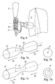
- Fig. 6 illustrates an inner operating mechanism of the tap handle 4 and a second embodiment of a dispensing line 10' including an integral valve 11' also shown in Figs. 7a, 7b, 7c and 7d .
- the dispensing line 10' is made of an elastomeric material and has an integral valve 11' at the dispensing end of the dispensing line 10'.
- the valve 11' comprises a segment defining a longitudinal direction along sets of arrows 28' shown in Figs. 7a and 7c .
- Figs. 7a and 7b constituting a perspective view and a vertical sectional view, respectively
- the segment constituting the integral valve 11' of the second embodiment of the dispensing line 10' is closed
- Figs. 7c and 7d constituting a perspective view and a vertical sectional view, respectively, the segment 11' is opened allowing beer to flow in the longitudinal direction of the segment and to be dispensed from a fluid outlet 27'.
- the segment 11' constituting the integral valve is in its closed position when relaxed as illustrated in Figs. 7a and 7b , and is shifted to its open position shown in Figs. 7c and 7d , provided the segment is compressed in a longitudinal direction as indicated by the arrows 28' in Fig. 7c providing a longitudinal compression of the segment, thereby opening the segment.
- the valve constituted by the segment 11' in its open position shown in Figs. 7c and 7d when relaxed and is caused to be shifted from its open position shown in Figs. 7c and 7d into its closed position shown in Figs. 7a and 7b by stretching the segment longitudinally by applying oppositely directed forces relative to the segment and pulling the segment longitudinally by applying oppositely directed forces as indicated by the arrows 28' shown in Fig. 7a .
- the second embodiment of the dispensing line 10' including the integral valve 11' shown in Figs. 7a-7d may be made from a composite foil structure comprising outer and inner foil layers, in which the inner layer or layers constitute or constitutes a soft layer providing the sealing off of the segment 11' in the closed position shown in Figs. 7a and 7b whereas the outer layer includes elastic memory for causing the segment to revert to its relaxed position being the closed position shown in Figs. 7a and 7b or the open position shown in Figs. 7c and 7d in the variant of the embodiment described above.
- Fig. 8 illustrates an inner operating mechanism of the tap handle 4 operating and a third embodiment of a dispensing line 10''' with the integral valve 11''' provided at the dispensing end of the dispensing line 10"'.
- Figs. 9a, 9b and 9c illustrate the third embodiment of a dispensing line 10''' made of an elastomeric material with the integral valve 11''' and a magnet assembly 36.
- the valve 11''' comprises two parts or segments, a first part or segment designated the reference numeral 31 and a second part or segment designated the reference numeral 32.
- the first part 31 constitutes an inlet to the valve 11'''
- the second part 32 defines a somewhat reduced diameter compared to the first part 31 and defines the outlet 27'''.
- a closure body constituted by a body of magnetic oil 38 is included which is preferably contained within a highly flexible elastomeric membrane or a wall located at the transition between the first part 31 and the second part 32.
- the magnetic oil 38 is shiftable within the valve 11''' by means of the magnet assembly 36 which is preferably constituted by a plurality of magnets located on a circular cylindrical surface juxtaposed the transition between the first part 31 and the second part 32 of the valve 11''' or alternatively is constituted by a ring-shaped circumferentially enclosing magnetic body.
- the magnet assembly 36 or the above described ring-shaped magnet may be substituted by an electromagnetic assembly which is connected to a DC power source for generating a magnetic field serving like the permanent magnets of the magnet assembly 36 or alternatively the ring-shaped magnet to influence the magnetic oil 38 and cause the magnetic oil to be shifted from its position shown in Fig. 9a to its position shown in Fig. 9b .
- the magnetic oil is located behind the transition between the first part 31 and the second part 32 allowing fluid to pass through the valve, i.e. allowing beer to be dispensed from the outlet 27''' whereas in Fig. 9b , the magnet assembly 36 is shifted forwards relative to the valve 11''' causing the magnetic oil 38 to be shifted into the transition between the first part 31 and the second part 32 and causing the film or membrane within which the magnetic oil is confined to close off the passage at the transition between the first part 31 and the second part 32.
- Figs. 10 , 10a and 10b illustrate a fourth embodiment of the dispensing line 10 iv made of an elastomeric material with the integral valve 11 iv .
- Figure 10 illustrates the dispensing line 10 iv in its state after its manufacture, e.g. after being moulded from an elastomeric material. In this state a movable element 40 is not yet everted. In Figs. 10a and 10b the movable element 40 is shown everted into its operational states.
- the dispensing line 10 is shown in its two distinct normal operational states in Figs. 10a and 10b , namely open and closed, respectively.
- the dispensing line 10 iv in general comprises a tubular segment 11 iv made of the same elastomeric material as the dispensing line 10 iv .
- the tubular segment 11 iv defines the fluid outlet 27 iv and a central point 20.
- the movable element 40 defines a direction of movement towards a central point 20 iv and is integrally connected to the tubular segment 11 iv by means of a pair of stretchable walls 42 and 44.
- the walls 42 and 44 are initially in a non-stretched state as shown in Fig. 10a .
- the movable element 40 when subjected to a force in the direction of the movement towards the central point 20, stretches the pair of walls 42 and 44 causing the movable element 40 to be contacted with a pair of seat points 46 and 48 and thereby shuts off the fluid outlet 27 iv . Conversely, the movable element 40 when not subjected to any forces allows the walls 42 and 44 to return to their initial non-stretched state and thereby the fluid outlet 27 iv is opened.
- Figs. 11 a and 11 b illustrate a fifth embodiment of the dispensing line 10 v made of an elastomeric material with the integral valve 11 v .
- the valve comprises a tubular segment defining the fluid outlet 27 v and is made, e.g. moulded of an elastomeric material.
- the tubular segment comprises a movable element 58 and a membrane 59.
- the membrane 59 has an elastic property and a position initially allowing the fluid outlet 27 iv to be open as is shown in Fig. 11 a.
- the movable element 58 is made, e.g. moulded, integral with a sidewall 60 of the tubular segment.
- the element 58 when subjected to a force in a downwards towards the fluid outlet 27 iv , forces the membrane 59 to be moved to block the fluid outlet 27 iv .
- the element 58 when the movable element 58 is not subjected to any force, the element 58 is returned to its initial state shown in Fig. 11a due to its elastic property and opens up the fluid outlet 27 iv .
- the membrane 59 is fixed at its one end to a sidewall 61 opposite to the sidewall 60.
- the membrane 59 is fixed to the sidewall 61 by means of a suitable process such as welding, gluing or is preferably integrally moulded with the tubular segment forming part of the dispensing line 10 v .
- the movable element 58 may initially as shown in Fig. 11 a be in a non-everted state, and as shown in Fig. 11 be forced into the everted state.
- the movable element 58 is of a massive elastomeric material.
- Figs. 12 , 12a and 12b illustrate a sixth embodiment of the dispensing line 10 vi made of an elastomeric material with the integral valve 11 vi .
- the sixth embodiment of the dispensing line 10 vi with the integral valve 11 vi shown 12, 12a and 12b is initially produced in a non-everted state as is shown in Fig. 12 in which a dome-shaped wall part 50 is located opposite to the fluid outlet 27 vi .
- a hollow shaft 52 extends which hollow shaft 52 defines a proximal end 54 at the outer surface of the dome-shaped wall part 50 and a distal end at which a hollow Y-shaped closure body 56 is provided.
- the hollow shaft 52 and the Y-shaped closure body 56 is everted and by the eversion of the hollow shaft 52 and the hollow Y-shaped closure body 56, the dome-shaped wall part 50 is deformed into a substantially planar configuration as shown in Fig. 12a biasing the everted Y-shaped closure body 56 into engagement with the outer end walls of the fluid outlet 27 vi closing off the fluid outlet 27 vi .
- valve 11 vi is closed as the wall part 50 forces the closure body 56 into sealing engagement with the fluid outlet 27 vi due to the biasing effect as the wall part 50 is bent from its initial convex dome-shaped configuration as shown in Fig. 12 into its substantially planar deformed configuration shown in Fig. 12a .
- valve 11 vi is opened as the wall part 50 is further deformed and forced downwardly causing the closure body 56 to be disengaged from its sealing engagement with the fluid outlet 27 vi , consequently allowing beer to be dispensed from the fluid outlet 27 vi .
Landscapes
- Engineering & Computer Science (AREA)
- General Engineering & Computer Science (AREA)
- Mechanical Engineering (AREA)
- Devices For Dispensing Beverages (AREA)
- Containers And Packaging Bodies Having A Special Means To Remove Contents (AREA)
Priority Applications (2)
| Application Number | Priority Date | Filing Date | Title |
|---|---|---|---|
| EP07388022A EP1982953A1 (fr) | 2007-04-16 | 2007-04-16 | Circuit de distribution doté d'une soupape intégrée |
| PCT/DK2008/000139 WO2008125114A2 (fr) | 2007-04-16 | 2008-04-16 | Dispositif de distribution fait d'un matériau élastomérique |
Applications Claiming Priority (1)
| Application Number | Priority Date | Filing Date | Title |
|---|---|---|---|
| EP07388022A EP1982953A1 (fr) | 2007-04-16 | 2007-04-16 | Circuit de distribution doté d'une soupape intégrée |
Publications (1)
| Publication Number | Publication Date |
|---|---|
| EP1982953A1 true EP1982953A1 (fr) | 2008-10-22 |
Family
ID=38441575
Family Applications (1)
| Application Number | Title | Priority Date | Filing Date |
|---|---|---|---|
| EP07388022A Withdrawn EP1982953A1 (fr) | 2007-04-16 | 2007-04-16 | Circuit de distribution doté d'une soupape intégrée |
Country Status (2)
| Country | Link |
|---|---|
| EP (1) | EP1982953A1 (fr) |
| WO (1) | WO2008125114A2 (fr) |
Citations (6)
| Publication number | Priority date | Publication date | Assignee | Title |
|---|---|---|---|---|
| GB2181818A (en) * | 1985-10-18 | 1987-04-29 | Ti Domestic Appliances Ltd | Fluid flow control valve |
| US4690375A (en) * | 1986-07-07 | 1987-09-01 | Vorhis Daniel J | Self closing squeeze valve |
| US4887742A (en) * | 1988-06-21 | 1989-12-19 | The Meyer Company | One piece dispensing valve |
| US5265847A (en) * | 1993-05-03 | 1993-11-30 | Vorhis Daniel J | Squeeze valve with augmented sealing |
| WO1999012844A2 (fr) * | 1997-09-09 | 1999-03-18 | Benjamin Grill | Ensemble robinet adapte a un distributeur de liquide |
| US6454742B1 (en) * | 2000-03-01 | 2002-09-24 | Sherwood Services, Ag | Valve cuff for a fluid administration system |
Family Cites Families (1)
| Publication number | Priority date | Publication date | Assignee | Title |
|---|---|---|---|---|
| KR970009635B1 (ko) * | 1995-02-06 | 1997-06-17 | 송정식 | 탄산수 병뚜껑 |
-
2007
- 2007-04-16 EP EP07388022A patent/EP1982953A1/fr not_active Withdrawn
-
2008
- 2008-04-16 WO PCT/DK2008/000139 patent/WO2008125114A2/fr not_active Ceased
Patent Citations (6)
| Publication number | Priority date | Publication date | Assignee | Title |
|---|---|---|---|---|
| GB2181818A (en) * | 1985-10-18 | 1987-04-29 | Ti Domestic Appliances Ltd | Fluid flow control valve |
| US4690375A (en) * | 1986-07-07 | 1987-09-01 | Vorhis Daniel J | Self closing squeeze valve |
| US4887742A (en) * | 1988-06-21 | 1989-12-19 | The Meyer Company | One piece dispensing valve |
| US5265847A (en) * | 1993-05-03 | 1993-11-30 | Vorhis Daniel J | Squeeze valve with augmented sealing |
| WO1999012844A2 (fr) * | 1997-09-09 | 1999-03-18 | Benjamin Grill | Ensemble robinet adapte a un distributeur de liquide |
| US6454742B1 (en) * | 2000-03-01 | 2002-09-24 | Sherwood Services, Ag | Valve cuff for a fluid administration system |
Also Published As
| Publication number | Publication date |
|---|---|
| WO2008125114A3 (fr) | 2009-04-16 |
| WO2008125114A2 (fr) | 2008-10-23 |
Similar Documents
| Publication | Publication Date | Title |
|---|---|---|
| US8328113B2 (en) | Snap-fit valve and straw assembly and method of using same | |
| EP2771252B1 (fr) | Ensemble de distribution de fluide | |
| CA2740531C (fr) | Soupape | |
| US7708025B2 (en) | Poppet valve member | |
| AU689554B2 (en) | Back-flow preventing bag valve for bag-in-box container | |
| MX2011004272A (es) | Valvula y dispensador que la comprende. | |
| US20130140334A1 (en) | Flexible pouring spout | |
| EP2391572B1 (fr) | Élément de soupape pour ensemble distributeur de boissons | |
| EP1982953A1 (fr) | Circuit de distribution doté d'une soupape intégrée | |
| TWI510211B (zh) | 盛水裝置 | |
| JP4921477B2 (ja) | 液体容器用の分配用栓 | |
| WO2010046391A1 (fr) | Élément de vanne pour ensemble distributeur de boisson | |
| AU2006209845B2 (en) | An integrated fitment for aseptic packaging | |
| US20090127285A1 (en) | Dispensing device | |
| WO2006051569A1 (fr) | Robinet hautement impermeable a l'oxygene, destine a la distribution de liquides contenus dans des recipients, particulierement adaptee pour des applications aseptiques | |
| DE602004008232D1 (de) | Trinkverschluss für Getränkebehälter | |
| EP2639198A1 (fr) | Soupape de décharge de liquides provenant de récipients |
Legal Events
| Date | Code | Title | Description |
|---|---|---|---|
| PUAI | Public reference made under article 153(3) epc to a published international application that has entered the european phase |
Free format text: ORIGINAL CODE: 0009012 |
|
| AK | Designated contracting states |
Kind code of ref document: A1 Designated state(s): AT BE BG CH CY CZ DE DK EE ES FI FR GB GR HU IE IS IT LI LT LU LV MC MT NL PL PT RO SE SI SK TR |
|
| AX | Request for extension of the european patent |
Extension state: AL BA HR MK RS |
|
| AKX | Designation fees paid | ||
| REG | Reference to a national code |
Ref country code: DE Ref legal event code: 8566 |
|
| STAA | Information on the status of an ep patent application or granted ep patent |
Free format text: STATUS: THE APPLICATION IS DEEMED TO BE WITHDRAWN |
|
| 18D | Application deemed to be withdrawn |
Effective date: 20090423 |