EP1982940A2 - Equipment for transferring sheets with change of direction - Google Patents
Equipment for transferring sheets with change of direction Download PDFInfo
- Publication number
- EP1982940A2 EP1982940A2 EP08103625A EP08103625A EP1982940A2 EP 1982940 A2 EP1982940 A2 EP 1982940A2 EP 08103625 A EP08103625 A EP 08103625A EP 08103625 A EP08103625 A EP 08103625A EP 1982940 A2 EP1982940 A2 EP 1982940A2
- Authority
- EP
- European Patent Office
- Prior art keywords
- sheets
- engagement
- along
- equipment
- entering
- Prior art date
- Legal status (The legal status is an assumption and is not a legal conclusion. Google has not performed a legal analysis and makes no representation as to the accuracy of the status listed.)
- Withdrawn
Links
- 230000008859 change Effects 0.000 title claims abstract description 25
- 230000033001 locomotion Effects 0.000 claims abstract description 65
- 230000000994 depressogenic effect Effects 0.000 claims description 18
- 238000011144 upstream manufacturing Methods 0.000 claims description 3
- 239000011248 coating agent Substances 0.000 claims 1
- 238000000576 coating method Methods 0.000 claims 1
- 238000003780 insertion Methods 0.000 description 5
- 230000037431 insertion Effects 0.000 description 5
- 230000007246 mechanism Effects 0.000 description 5
- 230000009471 action Effects 0.000 description 2
- 230000005540 biological transmission Effects 0.000 description 2
- 230000004044 response Effects 0.000 description 2
- 230000001360 synchronised effect Effects 0.000 description 2
- 230000001133 acceleration Effects 0.000 description 1
- 230000004913 activation Effects 0.000 description 1
- 238000010276 construction Methods 0.000 description 1
- 238000010586 diagram Methods 0.000 description 1
- 238000000034 method Methods 0.000 description 1
- 230000010355 oscillation Effects 0.000 description 1
- 230000002093 peripheral effect Effects 0.000 description 1
- 238000000926 separation method Methods 0.000 description 1
Images


Classifications
-
- B—PERFORMING OPERATIONS; TRANSPORTING
- B65—CONVEYING; PACKING; STORING; HANDLING THIN OR FILAMENTARY MATERIAL
- B65H—HANDLING THIN OR FILAMENTARY MATERIAL, e.g. SHEETS, WEBS, CABLES
- B65H29/00—Delivering or advancing articles from machines; Advancing articles to or into piles
- B65H29/12—Delivering or advancing articles from machines; Advancing articles to or into piles by means of the nip between two, or between two sets of, moving tapes or bands or rollers
- B65H29/14—Delivering or advancing articles from machines; Advancing articles to or into piles by means of the nip between two, or between two sets of, moving tapes or bands or rollers and introducing into a pile
- B65H29/145—Delivering or advancing articles from machines; Advancing articles to or into piles by means of the nip between two, or between two sets of, moving tapes or bands or rollers and introducing into a pile the pile being formed between the two, or between the two sets of, tapes or bands or rollers
-
- B—PERFORMING OPERATIONS; TRANSPORTING
- B65—CONVEYING; PACKING; STORING; HANDLING THIN OR FILAMENTARY MATERIAL
- B65H—HANDLING THIN OR FILAMENTARY MATERIAL, e.g. SHEETS, WEBS, CABLES
- B65H2301/00—Handling processes for sheets or webs
- B65H2301/30—Orientation, displacement, position of the handled material
- B65H2301/34—Modifying, selecting, changing direction of displacement
- B65H2301/341—Modifying, selecting, changing direction of displacement without change of plane of displacement
- B65H2301/3411—Right angle arrangement, i.e. 90 degrees
- B65H2301/34112—Right angle arrangement, i.e. 90 degrees changing leading edge
-
- B—PERFORMING OPERATIONS; TRANSPORTING
- B65—CONVEYING; PACKING; STORING; HANDLING THIN OR FILAMENTARY MATERIAL
- B65H—HANDLING THIN OR FILAMENTARY MATERIAL, e.g. SHEETS, WEBS, CABLES
- B65H2404/00—Parts for transporting or guiding the handled material
- B65H2404/10—Rollers
- B65H2404/14—Roller pairs
- B65H2404/141—Roller pairs with particular shape of cross profile
- B65H2404/1411—D-shape / cylindrical
-
- B—PERFORMING OPERATIONS; TRANSPORTING
- B65—CONVEYING; PACKING; STORING; HANDLING THIN OR FILAMENTARY MATERIAL
- B65H—HANDLING THIN OR FILAMENTARY MATERIAL, e.g. SHEETS, WEBS, CABLES
- B65H2404/00—Parts for transporting or guiding the handled material
- B65H2404/20—Belts
- B65H2404/26—Particular arrangement of belt, or belts
- B65H2404/261—Arrangement of belts, or belt(s) / roller(s) facing each other for forming a transport nip
-
- B—PERFORMING OPERATIONS; TRANSPORTING
- B65—CONVEYING; PACKING; STORING; HANDLING THIN OR FILAMENTARY MATERIAL
- B65H—HANDLING THIN OR FILAMENTARY MATERIAL, e.g. SHEETS, WEBS, CABLES
- B65H2511/00—Dimensions; Position; Numbers; Identification; Occurrences
- B65H2511/20—Location in space
- B65H2511/21—Angle
- B65H2511/212—Rotary position
-
- B—PERFORMING OPERATIONS; TRANSPORTING
- B65—CONVEYING; PACKING; STORING; HANDLING THIN OR FILAMENTARY MATERIAL
- B65H—HANDLING THIN OR FILAMENTARY MATERIAL, e.g. SHEETS, WEBS, CABLES
- B65H2513/00—Dynamic entities; Timing aspects
- B65H2513/50—Timing
- B65H2513/51—Sequence of process
Definitions
- the present invention relates to an equipment for transferring sheets with change of direction.
- the invention relates to an equipment for transferring sheets with change of direction according to the introductory portions of the main claims.
- Equipments for transferring sheets with change of direction are used in systems for the automatic processing and delivering of documents.
- the documents previously printed on sheets in vertical and in movement in the sense of a long edge should be moved in the sense of the short edge, without change of orientation for following processing of folding and insertion into envelope.
- an equipment for transfer sheets with change of direction comprising a box like structure with a mechanism of input, a mechanism of output for moving the sheets along a second direction and electromagnets actuatable for putting the entered sheets in engagement with the mechanism of output.
- the mechanism of input includes a series of rollers which move the sheets along a first direction up to a stop surface, with loss of engagement.
- the mechanism of output includes motorized rollers projecting from a surface of support of the entering sheet and upper pinch rollers connected with the electromagnets. When the leading edge of the entering sheet arrives at the stop surface, it is sensed by a photocell which enables the electromagnets to urge the pinch rollers downwardly to put the entered sheet against the motorized rollers for the transfer along the second direction.
- An equipment of this known type requires the complete emerging of the entered sheet along the second direction before the entering of a following sheet. Therefore this equipment is inherently slow, of limited flexibility and is unsuitable to be used in the current high velocity systems for the automatic processing of document.
- An object of the present invention is to accomplish an equipment for transferring sheets with change of direction of high reliability, which results fast, flexible and of relatively limited cost.
- the equipment for transferring sheets with change of direction for sheets entering along a first direction comprising output rollers for moving the sheets along a second direction, right-angled with respect to the first direction.
- the equipment further comprises members of engagement and movement actuatable for engaging and moving the sheets entering along the first direction along the second direction up to the engagement with the output rollers.
- the members of engagement and movement provide a condition of reception in which define a space of reception for the entering sheets and a condition of engagement and movement in which engage the entered sheets and move the sheets for the engagement with the output rollers, and in which the members of engagement and movement return to the condition of reception upon the engagement of the entered sheet with the output rollers for enabling a following sheet to enter and to be moved along the first direction jointly with the movement of the previous entered sheet along the second direction.
- the equipment for transferring sheets entering along a first direction comprises output rollers for moving the sheets along a second direction right angled with respect to the first direction, an actuating motor and a pair or more pairs of cyclically actuatable opposite wheels to engage and move along the second direction, up to the engagement with the output rollers, the sheets entering along the first direction.
- At least a wheel has one or more sectors provided for engagement with the other wheel and one or more depressed sectors, and in which the depressed sector is faced, or one of the depressed sectors is faced to the other wheel of the pair in a reference position to define a condition of receipt for the entering sheets, while the sector provided for engagement or each sector provided for engagement is designed to engage and move the sheets in the condition of engagement and movement.
- the actuating motor is provided to actuate at least a wheel from the reference position to positions of engagement and movement and return to the reference position, and each sheet entering along the first direction is moved up to the engagement with the output rollers by the one or more sectors provided for engagement, while a following sheet is allowed to enter and to be moved along a first direction up to the space defined by the depressed sectors for a new transferring of the sheets, jointly with the movement along the second direction of a sheet engaged by the output rollers.
- the equipment for transferring sheets entering along a first direction comprises an input section, of reception of sheets entering along a first direction, output rollers for moving the sheets along a second direction, right angled with respect to the first direction and control and actuation means for putting in engagement with the output rollers the sheets entered along the first direction.
- the equipment comprises: "O" rings of movement and contrast, lengthened along the first direction and having a lower branch tangent to a reference surface for engaging the entering sheets and moving the entering sheets along the reference surface, and members of engagement and movement of the said control and actuation means.
- the members of engagement and movement are operative in proximity of an edge of the sheets arranged on the reference surface, for moving the sheets up to the engagement with the output rollers.
- the equipment for transferring sheets entering along a first direction comprises output members adjacent to a section of output for moving the sheets along a second direction, right angled with respect to the first direction.
- the equipment further comprises: a moving device for longitudinally moving the longitudinally entering sheets on a reference surface; members of engagement and movement for putting the longitudinally entered sheets in engagement with the output members along the reference surface; and transversal guide elements for guiding, along the second direction, transversely entering sheets entering transversely from an input section of the equipment, opposite to the section of output, adjacently and underneath the reference surface and up to the output members.
- the equipment 21 comprises a front section 22, a back section 23 with a back wall 25 and lateral sections 24l and 24r with sides of support 25l and 25r.
- the front section 22 is of input for the equipment 21 and is designed for receiving sheets, represented with 26, in movement along a first direction 27.
- the sheets 26 are sequentially receivable with short separation between the edge of output of an entering sheet and the input edge of a following one.
- the lateral section 24l is of output for the equipment 21 and in which, through the lateral section 24l, the entered sheets 26 emerge along a second direction 28, right angled with respect to the first direction 27.
- the equipment 21 For the movement along the second direction 28, the equipment 21 includes output members and control and actuation means 31.
- the output members comprise, for instance, opposite output rollers 29 for engaging the entered sheets 26 and moving the sheets along the second direction 28, while the control and actuation means 31 puts the entered sheets 26 in engagement with the output rollers 29.
- the first direction 27 is parallel to a longitudinal axis 32 of the equipment.
- Such axis 32 is associated with the axis, conventionally longitudinal and parallel to the long edge of the sheets 26, while the second direction 28 is associated to the transversal axis parallel to the short edge of the sheets.
- control and actuation means 31 include members of engagement and movement 33 and 34, an actuating motor 36, a sheet sensor 35, a position sensor 37 and an electronic processing unit 38.
- the members of engagement and movement 33 and 34 are cyclically actuatable in the rotation, on control of the processing unit 38, for causing the entering sheets 26 which are moving along the first direction 27 to be temporarily engaged and moved, along the second direction 28, up to the engagement with the output rollers 29.
- the sheet sensor 35 is arranged upstream of the members of engagement and movement 33 and 34.
- the members of engagement and movement 33 and 34 provide a condition of reception for receiving the sheets and a condition of engagement and movement in which engage the sheets and move the sheets for the engagement with the output rollers 29.
- the members 33 and 34 operate on areas of the sheets adjacent to the input edge and, immediately thereafter, return to the condition of engagement for allowing the superimposition of the sheet while the underlying sheet is transferring along the second direction.
- the output rollers 29 are arranged out of the trajectory of the sheets in movement along the first direction and are kept in continuous rotation by an output motor 39 for a quick transfer of the engaged sheets along the second direction.
- the members of engagement and movement 33 and 34 respectively, include a pair of opposite wheels 421 and 42h and a pair of opposite wheels 431 and 43h, and in which the wheels 421, 42h and 431 and 43h rotate around axes parallel to the longitudinal axis 32.
- the wheels 421 and 431 are conveniently shaped so as to define each one at least one sector, specifically two engagement sectors 44-a, 44-b ( Figs. 5a and 5b ), for engaging the other wheel 42h and 43h and at least one depressed sector, specifically two depressed sectors 46-a and 46-b.
- the engagement sectors 44-a and 44-b are arranged at 180° the one from the other and are designed for engaging the sheets 26 and pinching the sheets against the wheel 42h and 43h in the condition of engagement and movement.
- the depressed sectors 46-a and 46-b are also arranged at 180° the one from the other and face the other wheels 42h and 43h in respective angular reference positions "0". In the reference positions, the depressed sections are spaced apart a gap "G" with respect to the wheel 42h and 43h and the shaped wheels 421 and 431 define a condition of receipt for the entering sheets 26.
- the opposite wheels 421, 42h and 431, 43h are actuatable in the rotation from the reference positions "0" to angular positions of engagement and movement and return to the reference positions.
- the engagement sectors are sized so that, with the rotation, the sheet 26 is engaged and moved up to the engagement with the output rollers 29. After the engagement of the sheets, the wheels 421, 42h and 431, 43h continue the rotation for a cycle of 180° with arrest at the reference positions "0" for receiving and transferring a following entered sheet.
- the equipment 21 includes a longitudinal moving device 47 for moving, by adherence, the entering sheets 26 along the first direction 27 on a reference surface 48.
- the control and actuation means 31 engage and move the sheets 26 in the second direction on the reference surface 48, with respect to the moving device 47, up to the engagement with the output members.
- the equipment 21 includes, between the sides 251 and 25r, a stop plate 51 for the input edge 52 of the received sheets, lower "O" rings of moving and support 531, 53cl, 53cr and 53r and upper “O” rings of movement and contrast 541, 54-c and 54r.
- the "O" rings are lengthened along the first direction 27 and define the reference surface 48 for the entering sheets 26.
- Edge lifting elements including ramp and step elements 561, 56c and 56r are associated to the lower "O" rings of moving and support 531, 53cl, 53cr and 53r and to the upper "O" rings of movement and contrast 541, 54-c and 54r for overlapping, without jamming, following sheets 26 on a sheet or on overlapped sheets of the reference surface 48.
- Each ramp and step element 561, 56c and 56r includes a ramp surface 57 and a step 58.
- the ramp 57 has a seat designed to receive the lower branch of the corresponding upper "O" rings of movement and contrast, while the sheet 26 or the overlapped sheets 26 are received and transferred, in plane, between the steps 58 of the ramp and step elements and the stop plate 51 according to a known technique.
- the sheet sensor 35 is close to one of the steps 58 and recognizes the passage of the edge of output of the sheet received on the reference surface 48.
- the pairs of opposite wheels 431 and 43h are operative in proximity of the input edges 52 of the received sheets 26 lying on the reference surface 48 for moving the sheets up to the engagement with the output rollers 29.
- the opposite wheels 421, 42h and 431, 43h project of few from the stop plate 51 for the engagement with the input edges 52 of the received sheets 26 and in proximity of the plate 51.
- the wheels 421, 42h and the wheels 431 and 43h operate on two different areas adjacent at the edges of input 52, in conditions of synchronism. It ensures the transversal shifting of the sheets with constant orientation and without oscillations.
- the opposite wheels 421, 42h and 431, 43h include each one a substantially frusto-conical tapered surface 63 for the received sheet 26.
- Each wheel 431, 43h is provided of a peripheral band 64 in a material of high adherence for a sure pinching with the sheets 26 in the condition of engagement.
- the wheels 421 and 42h of the member of engagement and movement 33 are mounted at the ends of two support shafts 61l and 61 h, while the wheels 431 and 43h of the member of engagement and movement 34 are mounted at the ends of two support shafts 621 and 62h.
- the shafts 61l, 61h and 621, 62h are mounted with the end projecting from the stop plate 51.
- the actuating motor 36 is of brushless D.C. type, with a position encoder 66, connected in the rotation to the support shafts 61l and 621 of the shaped wheels 421 and 431 through a transmission belt 67.
- the shafts 61l and 621 are connected in synchronism with the support shafts 61 h and 62h of the other wheels 42h and 43h through a chain of gears 68.
- the processing unity 38 responds to a signal from the sheet sensor 35 to activate, in intermittent way, the actuating motor 36.
- the processing unity drives the motor 36 with a law of motion, which is optimized for a limited impact at the moment of the contact of the engagement sectors 44a, 44b with the sheet or with the sheets and against the other wheel 42h, 43h, for a high velocity when the sheet or the sheets are pinched between the opposite wheels and a quick return to the condition of receipt of the equipment.
- the synchronous motorization between the lower wheels and the upper wheels assures pinching without slide both for the moving of single sheets and for the moving of overlapped sheets.
- the position sensor 37 is designed to recognize the passage of an index 69 keyed on the shaft of support 61l of the shaped wheel 421 and to supply a zero signal "R".
- the processing unit 38 responds to the signal "R" to identify one of the reference angular positions "0" of the shaped wheels 421 and 431 and the condition of receipt for the entering sheets 26.
- the longitudinal moving device 47 is defined by the lower "O" rings of moving and support 531, 53-c and 53r and the upper "O" rings of movement and contrast 541, 54-cl, 54-cr and 54r.
- the "O" rings of moving and support 531, 53-c and 53r are tensioned and moved by respective front lower pulleys 71f keyed on a shaft 72f and back lower pulleys 71 r rotatable on a shaft 72r, while the "O" rings of movement and contrast 541, 54cl, 54cr and 54r are tensioned and moved by front upper pulleys 73f keyed on a shaft 74f and back upper pulleys 73r rotatable on a shaft 74r.
- the shafts 72f and 74f are supported in rotatable way between the sides 251 and 25r.
- the stop plate 51 is arranged in front of the pulleys 71 r and 73r and provides notches for the passage of the above described upper and lower "O" rings.
- An input motor 76 rotates the lower pulleys 71f and the upper pulleys 73f, in synchronous way, through a transmission belt 77 and a pulley 78 keyed on the shaft 72f and through gears 79 between the shafts 72f and 74f.
- the received sheets 26 are arranged on the reference surface 48 and moved on this surface between the upper branches of the "O" rings of moving and support 531, 53-c and 53r and the lower branches of the "O" rings of movement and contrast 541, 54cl, 54cr and 54r.
- the input motor 76 is of brushless D.C. type and is controlled by a position encoder 81 ( Fig. 6 ) keyed on the shaft 72f.
- the processing unit 38 responds to the signals from the encoder 81 for adjusting the moving speed of the sheets 26 on the basis of the requests of the equipment feeding the entering sheets 26.
- the longitudinal moving device 47 works on the opposite faces of a single sheet and, in the case of overlapped sheets, on the lower face of the underlying sheet and on the upper face of the upper sheet. It ensures the transfer of sheets overlapped in unitary ways and at high velocity.
- the equipment 21 can be arranged, advantageously, downstream of a so-called "double cutter” having possibility of cutting both of single sheets and of overlapped sheets.
- the device 47 provides to overlap a sheet 26 on a sheet or sheets lying on the upper branch of the lower "O" rings.
- the opposite output rollers 29 include a pair of rollers 82l and 82h a little upstream from the members 33 and 34 and a pair of rollers 83l and 83h of a little downstream from the ramp and step elements, keyed on a lower shaft 84l and on an upper shaft 84h.
- the shafts 84l and 84h are supported in the rotation at the outside of the side 25f, parallel to the axis 32 and so that the nipping area of the rollers 82l and 82h and of the rollers 83l and 83h results on the reference surface 48.
- the output motor 39 is connected in the rotation with the lower shaft 84l through belt and pulley, while the upper shaft 84h is in synchronism with the shaft 84l through gears 86. Also the output motor 39 is of brushless D.C. type, controlled by a position encoder 87 keyed on the shaft 84l. The signals from the encoder 87 are used by the processing unit 38 to adjust the moving speed of the sheets 26 emerging along the second direction, on the basis of the requests of the receiving equipments and the dimensions of the sheets.
- the electronic processing unit 38 ( Fig. 6 ) comprises an interface unit 91, a microprocessor 92 and a drive and interface unit 93.
- the interface unit 91 is connected to the system to which the equipment 21 is connected, while the microprocessor 92 works on the basis of information received by the system and in relation with the operative specifications of the sheets to be processed.
- the processing unit 38 drives in continuous way the output motor 39 and the input motor 76 in response to information of velocity and control derived by the signals from the encoders 87 and 81. Moreover, the unit 38 drives the actuating motor 36 in response to signals from the sheet sensor 35, according to a cycle of engagement, movement and release of the shaped wheels with respect to the sheets 26. This cycle provides a period of movement with steps of acceleration and brake and a period of arrest associated to the movement of the sheet along the second direction, with control by the position encoder 66 and return to the reference positions "0."
- the structure of the equipment 21 allows the transferring of single sheets and overlapped sheets and with liberty on the number of the overlapped sheets and the transferring of bundles of sheets, by modifying the distance between the wheels 421 and 42h and the wheels 431 and 43h.
- the equipment 21 In the operation for the transferring of sheets, the equipment 21 is in a condition of reception in which the input motor 76 is energized for the actuation of the "O" rings 531, 53cl, 53cr and 53r and of the "O" rings 541, 54-c and 54r. At the same time, the output motor 39 is energized for a continuous rotation of the output rollers 29. In turn, the shaped wheels 421 and 431 ( Fig. 5a ) are in the reference positions, spaced apart of the gap "G" from the opposite wheels 431 and 43h.
- a sheet 26 entering in the input section 22 is nipped between the upper branches of the "O" rings 531, 53cl, 53cr and 53r and the lower branches of the "O” rings 541, 54c and 54r.
- the "O” rings move the sheet along the first direction 32, with lifting of the input edge on the ramp and step elements 561, 56c and 56r, following lending on the reference surface 48 ( Fig. 2a ) and moving on the surface 48.
- the processing unit 38 Fig. 6
- the stop plate 51 holds back the sheet 26, against the sliding action of the "O", while the sectors 44° and 44b of the shaped wheels 421 and 431 engage, in tandem, two areas of the sheet adjacent to the input edge 52.
- the entered sheet 26 is moved in the second direction 28, carrying the lateral edge up to the engagement with the output rollers 29.
- the rollers 29 now drag the sheet in the second direction 28, while the shaped wheels 421 and 431 return to the condition of receipt.
- the equipment 21 can receive and moving longitudinally a following sheet 26.
- the input edge 52 of the following entering sheet will be lifted by the ramp and step elements 561, 56c and 56r, and subsequently depressed with partial superimposition on the sheet 26 lying on the reference surface 48 and emerging from the equipment. While the preceding sheet completely disengages the upper and lower "O" rings, the following sheet enters the gaps "G", for a new energization of the actuating motor 36, on the passage of the edge of output of the sheet in front of the sheet sensor 35, and another cycle of transferring.
- the above described transferring of sheets also applies to the receiving of two overlapped sheets, as in the case in which the equipment 21 is arranged downstream of a double cutter.
- the equipment 21 can also operate for forming a bundle of sheets in the space defined between the steps 58 of the ramp and step elements and the stop plate 51, with the edges 52 received in the gaps "G".
- the processing unit 38 will drive the actuating motor 36 after the reception of a number of signals from the sheet sensor 35 corresponding to the number of sheets which will form the bundle.
- the whole bundle will be moved by the wheels 421 and 42h and the wheels 431 and 43h up to the output rollers 29 for the following transferring in the second direction.
- the equipment 21 can optionally provide output rollers 94 ( Figs. 4 and 5 ) arranged adjacent to the side 25r and having sense of rotation opposed to the one of the rollers 29 for transferring the sheets 26 from the section 24r of the equipment along the second direction but in an opposite sense 96.
- output rollers 94 Figs. 4 and 5
- the sheets will be transferred with output from the lateral section 241, while the sheets will be transferred with output from the section 24r for a sense of rotation opposed of the wheels 421, 43h.
- 121 a variant of equipment for transferring sheets with change of direction, similar to the equipment 21 of Fig. 1 , including a fixed lower frame 1221 and a mobile upper frame 122h, and in which the upper frame 122h is provided for being positioned between an operative position and a position of service.
- the lower frame 1221 includes the back wall 25 and the sides 251 and 25r.
- the mobile frame 122h has two sides 1231 and 123r lined up with the sides 251 and 25r and is fulcrumed on the frame 1221 through pivots 1241 and 124r and lugs 1261 and 126r adjacent to the back section 23. In the operative position ( Fig.
- the frame 122h is horizontal, with the lower edges of the sides 1231 and 123r in contact with the upper edges of the sides 251 and 25r, while the section 22 corresponds to the front portion of the frames 1221 and 122h.
- the frame 122h In the position of service ( Fig. 9 ), the frame 122h is inclined upwardly with respect to the frame 1221 and allows the access to the frame 1221 and the lower components.
- the equipment 121 presents a reference surface 127 defined in the upper frame 122h and a stop surface 128 defined in the lower frame 1221, for the sheets 26 entering along the first direction 27.
- the reference surface 127 is horizontal, arranged between the front section 22 and the back section 23, while the stop surface 128 is adjacent to the section 23.
- the lateral section 24r is of output for the equipment 121 and, through this lateral section, the sheets 26 emerge along a second direction 129, right angled with respect to the first direction 27 and according to the transversal axis of the sheets 26.
- the equipment 121 comprises functional components equal to the functional components of the equipment 21, including the opposite output rollers 29, the members of engagement and movement 33 and 34 and the relative sensors and different functional components, including a longitudinal moving device 131, edge lifting elements 132 and an electronic processing unit 133.
- the longitudinal moving device 131 is actuated by an input motor 76 for moving the entering sheets 26 along the first direction 27 on the reference surface 127.
- the edge lifting elements 132 are arranged at the input and are associated to the moving device 131 for overlapping, without jamming, following entering sheets on the sheet of the reference surface 127 or on sheets overlapped of the surface 127.
- the output rollers 29 are kept in continuous rotation by the output motor 39 to engage the sheets 26 and move the sheets along the second direction 129.
- the moving device 131 includes, arranged in vertical, input pulleys 1371, 137cl, 137cr and 137r, front pulleys, 1381, 138c and 138r, back pulleys 1391, 139c and 139r and "O" rings or belts of movement and contrast, in detail "O" rings 141l, 141c and 141 r, between the front and back pulleys.
- the input pulleys, 1371, 137cl, 137cr and 137r are keyed on a shaft 137 of the frame 1221 and, in the operative condition of the frame 122h, these pulleys are below and in condition of tangency with respect to the reference surface 127.
- the front pulleys, 1381, 138c and 138r are keyed on a shaft 138 of the frame 122h and are arranged above and tangent with respect to the reference surface 127.
- the back pulleys 1391, 139c and 139r are coaxial with the pivots 1241 and 124r of fulcrum for the frame 122h and are supported in rotatable way by lugs of the frame 1221 adjacent to the back section 23.
- the pulleys 1391, 139c and 139r are arranged above and in condition of tangency with respect to the surface 127.
- the input pulleys 1371, 137cl, 137cr and 137r are connected in the rotation with the input motor 76 through the shaft 137 and through pulleys and a toothed belt.
- the motor 76 also actuates the front pulleys, 1381, 138c and 138r through the shaft 137 and a pair of gears including a gear 1401 keyed on the shaft 137 and a gear 140h keyed on the shaft 138.
- the pulley 1381 is arranged at the right of the pulley 1371, the pulley 138 is in central position between the pulleys 137cl and 137cr and the pulley 138r is at the left of the pulley 137r.
- the gear 140h is disengaged from the gear 1401.
- the "O" rings of movement and contrast 141l, 141c and 141 r ( Figs. 7 , 8 and 8a ) are longitudinally lengthened, engaged between the front pulleys, 1381, 138c and 138r and the back pulleys 1391, 139c and 139r.
- the lower branches of the "O" rings 141l, 141c and 141r are adjacent to the reference surface 127 and, in the use, are designated for cooperating with the sheets 26 of the reference surface 127 for longitudinally moving the sheets along the surface 127.
- the edge lifting elements 132 include lower contrast pulleys 1421, 142c and 142r, mounted on the frame 1221, and which are designed to cooperate with the "O" rings 141l, 141c and 141 r.
- Each pulley 1421, 142c and 142r is provided of a notch with small sides 143.
- the notches of the pulley 1421, 142c and 142r are coupled with the lower branches of the "O" rings 141l, 141c and 141 r, while the small sides 143 project of few from the surface 127.
- the equipment 121 includes transversal guide elements 144 for transversely entering sheets 146 from the lateral sections 241.
- the section 241 represents a transversal input, opposite to the sector 24r, of output, along the second direction 129, for the transfer without change of direction up to the output members 29.
- the guide elements 144 can guide sheets 146 of large transversal dimensions, also through the space of reception between the wheels 421, 42h and 431, 43h, up to the output rollers 29, for moving these sheets along the second direction 129.
- the transversal guide elements 144 include an upper laminar guide 147 and a lower laminar guide 148.
- the guide 147 is mounted on the bottom of the mobile frame 122h, adjacent to the lower branches of the "O" rings, and defines the reference surface 127, while the guide 148 is mounted on an upper portion of the frame 122 parallel, in the use, with the guide 147.
- the guides 147 and 148 form, in the operative conditions, a passage for the sheets 146 underneath the reference surface 127.
- the laminar guides 147 and 148 include, where necessary, suitable openings to freely lodge the contrast pulleys 1421, 142c and 142r and the shaped wheels 421, 42h and 431, 43h.
- the equipment 121 can be associated or can integrate a transversal insertion device for entering the sheets 146 through the transversal guide elements 144.
- the equipment 121 can longitudinally introduce the sheets 26 and move the sheets along the second direction 129 with right angled change of direction, or receive and transversally transfer the sheets 146 without change of direction.
- the operator can access the lower laminar guide 148 for the removal of possible jammed sheets.
- the equipment 161 is similar to the equipment 121 and integrates a transversal insertion device, represented with 162. With respect to the equipment 121, the equipment 161 has differences regarding some component of the transversal guide elements, herein represented with 163.
- the device 162 includes a support plate 164, transport belts 166 with upper branches slideable on the plate 164 and a transversal input motor 167 controlled by the electronic unit 133 for the feeding of the belts 166.
- the insertion device 162 presents a section external to the equipment 161 and an internal section.
- the plate 164 and the belts 166 transversally project from the lateral section 241 and are designed for receiving sheets 168 to be transferred without change of direction.
- the plate 164 and the belts 166 form the lower portion of the transversal guide elements 163.
- the upper portion of the elements 163 is formed by an upper laminar guide 169 equal to the guide 147 of Fig. 8 .
- the plate 164 and the belts 166 define the passage for the sheets 168 underneath the upper laminar guide 169 between the section of output 24r and the input section 24l.
- the insertion device 162 includes a counter plate 170, coupable with the external section of the support plate 164.
- the counter plate 170 supports small balls 157, of known type, lodged in respective cylindrical seats above the belts 153 and spring urged against the belts 166 to improve the transport of the sheets 146.
- the belts 166 allow the device 162 to transfer, without change of direction, sheets 168 having transversal dimensions less of the distance between the sides 24l and 24r of the frame 122l and, particularly, A5 sheets in the sense of the long edge.
- the equipment 161 can longitudinally introduce the sheets 26 and move the sheets along the second direction 129 with change of direction, or receive and transversally transfer the sheets 168 without change of direction. Possible jams can be removed, by accessing the plate 164 and the belts 166 in the condition of service of the frame 122h.
- the equipment 161 can use a lengthened counter plate (not shown) which extends along the external section and the internal section of the device 162.
- the small balls 157r are also arranged along the internal section of the equipment for improving the transport of the sheets 146 along the whole extension of the plate 164 and of the belts 166.
- the lengthened counter plate is coupable with the support plate 164 and with the belts 166 in the condition of service of the frame 122h, while the equipment 161 is operative exclusively for the transfer of the sheets 171 without change of direction.
- the equipment 176 includes the longitudinal moving device 131 with "O" rings and the pulleys of lifting, the output rollers 29 adjacent to the section 24r and the transversal guide elements 144. On the contrary, the equipment 176 has a different arrangement for the members of engagement and movement, herein represented with 177 and 178.
- the members 177 and 178 are similar to the members 33 and 34 and comprise the pair of opposite wheels 421 and 42h and the pair of opposite wheels 431 and 43h actuatable between the condition of reception and the condition of engagement and movement for the sheets 26.
- the members of engagement and movement 177 and 178 are arranged parallel to the output rollers 29 between the "O" rings and the output rollers and operate on areas of the sheets 26 adjacent to a lateral edge 179.
- the guide elements 144 have lateral openings for the members 177 and 178 and guide the sheets 146 through the space of reception between the wheels 421, 42h and 431, 43h, up to the output rollers 29, for the moving of the sheets along the second direction.
- the equipments 121, 161, 176 In the operative conditions for the transferring of the sheets 26, the equipments 121, 161, 176 is in a condition of reception and in which the motor 76 is energized for the actuation of the "Or" ring 141l, 141c and 141 r.
- the output motor 36 is also energized and holds in continuous rotation the output rollers 29.
- the shaped wheels 421 and 431 are in the reference position
- a sheet 26 entering the input section 22 is nipped and moved by the pulleys 1371, 137c and 137r and the pulleys 1381, 138c and 138r and subsequently moved by the lower branches of the "O" rings along the surface 127. Then, through the small sides 143, the "O" rings lift the input edge of the entering sheet 26 and allow the sheet to fall on the surface 127 to overlap, without jamming, following entering sheets on a sheet or on preceding sheets, arranged on the surface 127. Subsequently, the "O” rings move the sheet on the surface 127, up to the stop against the surface 128.
- the processing unity energizes the actuating motor for the cyclical rotation of 180 degrees of the wheels 421, 42h and 431, 43h.
- the equipments 121, 161 engage in tandem two areas of the sheet adjacent to the input edge 52.
- the equipment can receive a following sheet 26.
- the input edge 52 of the incoming sheet is lifted for the combined action of the "O" rings 141l, 141c and 141 r and the contrast pulleys 1421, 142c and 142r. Thereafter, the input edge 52 is depressed with partial superimposition on the sheet 26 lying on the reference surface 127 and in output.
- the wheels 421 and 431 engage areas of the lateral edge 179 adjacent to the section 124r.
- the sheet 26 is moved in the second direction up to the engagement of the lateral edge 179 with the output rollers 29 for the transport in the direction 129 and while the wheels 421 and 431 return in the condition of receipt.
- Also in the equipment 176 is possible to receive a sheet 26 during the shifting of the sheet 26 in the second direction, up to the time in which the preceding sheet has not completely abandoned the engagement with the wheels 421 and 42h and the wheels 43l and 43h.
Landscapes
- Engineering & Computer Science (AREA)
- Mechanical Engineering (AREA)
- Delivering By Means Of Belts And Rollers (AREA)
- Shaping Of Tube Ends By Bending Or Straightening (AREA)
- Decoration By Transfer Pictures (AREA)
Abstract
Description
- The present invention relates to an equipment for transferring sheets with change of direction.
- More specifically, the invention relates to an equipment for transferring sheets with change of direction according to the introductory portions of the main claims.
- Equipments for transferring sheets with change of direction, in particular right angle transfer equipments, are used in systems for the automatic processing and delivering of documents. Typically, the documents previously printed on sheets in vertical and in movement in the sense of a long edge should be moved in the sense of the short edge, without change of orientation for following processing of folding and insertion into envelope.
- It is known an equipment for transfer sheets with change of direction, of the type above mentioned, comprising a box like structure with a mechanism of input, a mechanism of output for moving the sheets along a second direction and electromagnets actuatable for putting the entered sheets in engagement with the mechanism of output. The mechanism of input includes a series of rollers which move the sheets along a first direction up to a stop surface, with loss of engagement. The mechanism of output includes motorized rollers projecting from a surface of support of the entering sheet and upper pinch rollers connected with the electromagnets. When the leading edge of the entering sheet arrives at the stop surface, it is sensed by a photocell which enables the electromagnets to urge the pinch rollers downwardly to put the entered sheet against the motorized rollers for the transfer along the second direction.
- An equipment of this known type requires the complete emerging of the entered sheet along the second direction before the entering of a following sheet. Therefore this equipment is inherently slow, of limited flexibility and is unsuitable to be used in the current high velocity systems for the automatic processing of document.
- An object of the present invention is to accomplish an equipment for transferring sheets with change of direction of high reliability, which results fast, flexible and of relatively limited cost.
- This object is obtained by the equipment for transferring sheets with change of direction for sheets entering along a first direction, comprising output rollers for moving the sheets along a second direction, right-angled with respect to the first direction. The equipment further comprises members of engagement and movement actuatable for engaging and moving the sheets entering along the first direction along the second direction up to the engagement with the output rollers. The members of engagement and movement provide a condition of reception in which define a space of reception for the entering sheets and a condition of engagement and movement in which engage the entered sheets and move the sheets for the engagement with the output rollers, and in which the members of engagement and movement return to the condition of reception upon the engagement of the entered sheet with the output rollers for enabling a following sheet to enter and to be moved along the first direction jointly with the movement of the previous entered sheet along the second direction.
- According to another characteristic, the equipment for transferring sheets entering along a first direction comprises output rollers for moving the sheets along a second direction right angled with respect to the first direction, an actuating motor and a pair or more pairs of cyclically actuatable opposite wheels to engage and move along the second direction, up to the engagement with the output rollers, the sheets entering along the first direction. At least a wheel has one or more sectors provided for engagement with the other wheel and one or more depressed sectors, and in which the depressed sector is faced, or one of the depressed sectors is faced to the other wheel of the pair in a reference position to define a condition of receipt for the entering sheets, while the sector provided for engagement or each sector provided for engagement is designed to engage and move the sheets in the condition of engagement and movement. The actuating motor is provided to actuate at least a wheel from the reference position to positions of engagement and movement and return to the reference position, and each sheet entering along the first direction is moved up to the engagement with the output rollers by the one or more sectors provided for engagement, while a following sheet is allowed to enter and to be moved along a first direction up to the space defined by the depressed sectors for a new transferring of the sheets, jointly with the movement along the second direction of a sheet engaged by the output rollers.
- Further according to another characteristic, the equipment for transferring sheets entering along a first direction comprises an input section, of reception of sheets entering along a first direction, output rollers for moving the sheets along a second direction, right angled with respect to the first direction and control and actuation means for putting in engagement with the output rollers the sheets entered along the first direction. In particular, the equipment comprises: "O" rings of movement and contrast, lengthened along the first direction and having a lower branch tangent to a reference surface for engaging the entering sheets and moving the entering sheets along the reference surface, and members of engagement and movement of the said control and actuation means. The members of engagement and movement are operative in proximity of an edge of the sheets arranged on the reference surface, for moving the sheets up to the engagement with the output rollers.
- According to another characteristic, the equipment for transferring sheets entering along a first direction comprises output members adjacent to a section of output for moving the sheets along a second direction, right angled with respect to the first direction. The equipment further comprises: a moving device for longitudinally moving the longitudinally entering sheets on a reference surface; members of engagement and movement for putting the longitudinally entered sheets in engagement with the output members along the reference surface; and transversal guide elements for guiding, along the second direction, transversely entering sheets entering transversely from an input section of the equipment, opposite to the section of output, adjacently and underneath the reference surface and up to the output members.
- The characteristics of the invention will become clear from the description that follows, given purely by way of non-limiting example, with reference to the attached drawings, in which:
-
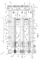
Fig. 1 represents a schematic plan view of an equipment for transferring sheets with change of direction according to the invention; -
Fig. 2 shows schematically a sectioned lateral view of the equipment ofFig. 1 ; -
Fig. 2a is a portion of the view ofFig. 2 in an operative condition of the equipment; -
Fig. 3 is a back partial view of the equipment ofFig. 1 ; -
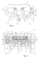
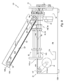
Fig. 4 shows schematically a partial section of the equipment of the invention according to the line IV-IV ofFig. 1 ; -
Fig. 5 is a partial view in enlarged scale of some details ofFig. 4 ; -
Fig. 5a shows the details ofFig. 5 in an operative condition; -
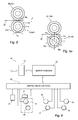
Fig. 6 is an electric block diagram of the equipment according to the invention; -
Fig. 7 shows a schematic plan view of a variant of the equipment ofFig. 1 ; -
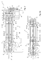
Fig. 8 represents a schematic sectioned lateral view of the equipment ofFig. 7 ; -
Fig. 8a is a portion of the view ofFig. 8 in an operative condition; -
Fig. 9 shows the lateral view ofFig. 8 in a condition of service; -
Fig. 10 represents a schematic plan view of another variant of the equipment ofFig. 7 in a particular operative configuration; and -
Fig. 11 is a plan view of a further variant of the equipment ofFig. 1 . - With reference to the
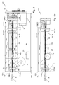
figures 1 and2 , an equipment for transferring sheets with change of direction is represented with 21. Theequipment 21 comprises afront section 22, aback section 23 with aback wall 25 andlateral sections 24l and 24r with sides ofsupport 25l and 25r. - The
front section 22 is of input for theequipment 21 and is designed for receiving sheets, represented with 26, in movement along afirst direction 27. Thesheets 26 are sequentially receivable with short separation between the edge of output of an entering sheet and the input edge of a following one. The lateral section 24l is of output for theequipment 21 and in which, through the lateral section 24l, the enteredsheets 26 emerge along asecond direction 28, right angled with respect to thefirst direction 27. - For the movement along the
second direction 28, theequipment 21 includes output members and control and actuation means 31. The output members comprise, for instance,opposite output rollers 29 for engaging the enteredsheets 26 and moving the sheets along thesecond direction 28, while the control and actuation means 31 puts the enteredsheets 26 in engagement with theoutput rollers 29. - The
first direction 27 is parallel to alongitudinal axis 32 of the equipment.Such axis 32 is associated with the axis, conventionally longitudinal and parallel to the long edge of thesheets 26, while thesecond direction 28 is associated to the transversal axis parallel to the short edge of the sheets. - According to the invention, the control and actuation means 31 include members of engagement and
movement motor 36, asheet sensor 35, aposition sensor 37 and anelectronic processing unit 38. The members of engagement andmovement processing unit 38, for causing the enteringsheets 26 which are moving along thefirst direction 27 to be temporarily engaged and moved, along thesecond direction 28, up to the engagement with theoutput rollers 29. - The
sheet sensor 35 is arranged upstream of the members of engagement andmovement movement output rollers 29. Themembers output rollers 29 are arranged out of the trajectory of the sheets in movement along the first direction and are kept in continuous rotation by anoutput motor 39 for a quick transfer of the engaged sheets along the second direction. - The members of engagement and
movement opposite wheels opposite wheels wheels longitudinal axis 32. Thewheels Figs. 5a and 5b ), for engaging theother wheel - The engagement sectors 44-a and 44-b are arranged at 180° the one from the other and are designed for engaging the
sheets 26 and pinching the sheets against thewheel other wheels wheel wheels sheets 26. Theopposite wheels sheet 26 is engaged and moved up to the engagement with theoutput rollers 29. After the engagement of the sheets, thewheels - According to the invention, the
equipment 21 includes a longitudinal movingdevice 47 for moving, by adherence, the enteringsheets 26 along thefirst direction 27 on areference surface 48. In the condition of engagement and movement, the control and actuation means 31 engage and move thesheets 26 in the second direction on thereference surface 48, with respect to the movingdevice 47, up to the engagement with the output members. - In a first embodiment of the
figures 1 and2 , theequipment 21 includes, between thesides stop plate 51 for theinput edge 52 of the received sheets, lower "O" rings of moving andsupport 531, 53cl, 53cr and 53r and upper "O" rings of movement andcontrast 541, 54-c and 54r. The "O" rings are lengthened along thefirst direction 27 and define thereference surface 48 for the enteringsheets 26. Edge lifting elements including ramp and stepelements support 531, 53cl, 53cr and 53r and to the upper "O" rings of movement andcontrast 541, 54-c and 54r for overlapping, without jamming, followingsheets 26 on a sheet or on overlapped sheets of thereference surface 48. - Each ramp and
step element ramp surface 57 and astep 58. Theramp 57 has a seat designed to receive the lower branch of the corresponding upper "O" rings of movement and contrast, while thesheet 26 or the overlappedsheets 26 are received and transferred, in plane, between thesteps 58 of the ramp and step elements and thestop plate 51 according to a known technique. - The
sheet sensor 35 is close to one of thesteps 58 and recognizes the passage of the edge of output of the sheet received on thereference surface 48. The pairs ofopposite wheels sheets 26 lying on thereference surface 48 for moving the sheets up to the engagement with theoutput rollers 29. - The
opposite wheels stop plate 51 for the engagement with the input edges 52 of the receivedsheets 26 and in proximity of theplate 51. Thewheels wheels input 52, in conditions of synchronism. It ensures the transversal shifting of the sheets with constant orientation and without oscillations. - The
opposite wheels tapered surface 63 for the receivedsheet 26. Eachwheel peripheral band 64 in a material of high adherence for a sure pinching with thesheets 26 in the condition of engagement. - The
wheels movement 33 are mounted at the ends of twosupport shafts 61l and 61 h, while thewheels movement 34 are mounted at the ends of twosupport shafts shafts stop plate 51. Theactuating motor 36 is of brushless D.C. type, with aposition encoder 66, connected in the rotation to thesupport shafts 61l and 621 of the shapedwheels transmission belt 67. In turn, theshafts 61l and 621 are connected in synchronism with thesupport shafts other wheels gears 68. - In the use, the
processing unity 38 responds to a signal from thesheet sensor 35 to activate, in intermittent way, theactuating motor 36. The processing unity drives themotor 36 with a law of motion, which is optimized for a limited impact at the moment of the contact of theengagement sectors other wheel - The synchronous motorization between the lower wheels and the upper wheels assures pinching without slide both for the moving of single sheets and for the moving of overlapped sheets.
- The
position sensor 37 is designed to recognize the passage of anindex 69 keyed on the shaft of support 61l of the shapedwheel 421 and to supply a zero signal "R". On initialization of theequipment 21, theprocessing unit 38 responds to the signal "R" to identify one of the reference angular positions "0" of the shapedwheels sheets 26. - The longitudinal moving
device 47 is defined by the lower "O" rings of moving andsupport 531, 53-c and 53r and the upper "O" rings of movement andcontrast 541, 54-cl, 54-cr and 54r. - The "O" rings of moving and
support 531, 53-c and 53r are tensioned and moved by respective frontlower pulleys 71f keyed on ashaft 72f and backlower pulleys 71 r rotatable on ashaft 72r, while the "O" rings of movement andcontrast 541, 54cl, 54cr and 54r are tensioned and moved by frontupper pulleys 73f keyed on ashaft 74f and backupper pulleys 73r rotatable on ashaft 74r. Theshafts sides stop plate 51 is arranged in front of thepulleys - An
input motor 76 rotates thelower pulleys 71f and theupper pulleys 73f, in synchronous way, through atransmission belt 77 and a pulley 78 keyed on theshaft 72f and throughgears 79 between theshafts sheets 26 are arranged on thereference surface 48 and moved on this surface between the upper branches of the "O" rings of moving andsupport 531, 53-c and 53r and the lower branches of the "O" rings of movement andcontrast 541, 54cl, 54cr and 54r. - The
input motor 76 is of brushless D.C. type and is controlled by a position encoder 81 (Fig. 6 ) keyed on theshaft 72f. Theprocessing unit 38 responds to the signals from theencoder 81 for adjusting the moving speed of thesheets 26 on the basis of the requests of the equipment feeding the enteringsheets 26. - The longitudinal moving
device 47 works on the opposite faces of a single sheet and, in the case of overlapped sheets, on the lower face of the underlying sheet and on the upper face of the upper sheet. It ensures the transfer of sheets overlapped in unitary ways and at high velocity. Thus, theequipment 21 can be arranged, advantageously, downstream of a so-called "double cutter" having possibility of cutting both of single sheets and of overlapped sheets. By means of the upper "O" rings, thedevice 47 provides to overlap asheet 26 on a sheet or sheets lying on the upper branch of the lower "O" rings. - The
opposite output rollers 29 include a pair ofrollers 82l and 82h a little upstream from themembers rollers 83l and 83h of a little downstream from the ramp and step elements, keyed on a lower shaft 84l and on anupper shaft 84h. Theshafts 84l and 84h are supported in the rotation at the outside of the side 25f, parallel to theaxis 32 and so that the nipping area of therollers 82l and 82h and of therollers 83l and 83h results on thereference surface 48. - The
output motor 39 is connected in the rotation with the lower shaft 84l through belt and pulley, while theupper shaft 84h is in synchronism with the shaft 84l through gears 86. Also theoutput motor 39 is of brushless D.C. type, controlled by aposition encoder 87 keyed on the shaft 84l. The signals from theencoder 87 are used by theprocessing unit 38 to adjust the moving speed of thesheets 26 emerging along the second direction, on the basis of the requests of the receiving equipments and the dimensions of the sheets. - The electronic processing unit 38 (
Fig. 6 ) comprises aninterface unit 91, amicroprocessor 92 and a drive andinterface unit 93. Theinterface unit 91 is connected to the system to which theequipment 21 is connected, while themicroprocessor 92 works on the basis of information received by the system and in relation with the operative specifications of the sheets to be processed. - The
processing unit 38 drives in continuous way theoutput motor 39 and theinput motor 76 in response to information of velocity and control derived by the signals from theencoders unit 38 drives theactuating motor 36 in response to signals from thesheet sensor 35, according to a cycle of engagement, movement and release of the shaped wheels with respect to thesheets 26. This cycle provides a period of movement with steps of acceleration and brake and a period of arrest associated to the movement of the sheet along the second direction, with control by theposition encoder 66 and return to the reference positions "0." - The structure of the
equipment 21 allows the transferring of single sheets and overlapped sheets and with liberty on the number of the overlapped sheets and the transferring of bundles of sheets, by modifying the distance between thewheels wheels - In the operation for the transferring of sheets, the
equipment 21 is in a condition of reception in which theinput motor 76 is energized for the actuation of the "O" rings 531, 53cl, 53cr and 53r and of the "O" rings 541, 54-c and 54r. At the same time, theoutput motor 39 is energized for a continuous rotation of theoutput rollers 29. In turn, the shapedwheels 421 and 431 (Fig. 5a ) are in the reference positions, spaced apart of the gap "G" from theopposite wheels - A
sheet 26 entering in theinput section 22 is nipped between the upper branches of the "O" rings 531, 53cl, 53cr and 53r and the lower branches of the "O" rings 541, 54c and 54r. The "O" rings move the sheet along thefirst direction 32, with lifting of the input edge on the ramp and stepelements Fig. 2a ) and moving on thesurface 48. Upon the passage of the edge of output in front of thesheet sensor 35, the processing unit 38 (Fig. 6 ) activates theactuating motor 36 for a cyclical rotation of 180 degrees of thewheels input edge 52 entering the gaps "G" between thewheels wheels - The
stop plate 51 holds back thesheet 26, against the sliding action of the "O", while the sectors 44° and 44b of the shapedwheels input edge 52. The enteredsheet 26 is moved in thesecond direction 28, carrying the lateral edge up to the engagement with theoutput rollers 29. Therollers 29 now drag the sheet in thesecond direction 28, while the shapedwheels - During the movement of the entered
sheet 26 in the second direction, theequipment 21 can receive and moving longitudinally a followingsheet 26. Theinput edge 52 of the following entering sheet will be lifted by the ramp and stepelements sheet 26 lying on thereference surface 48 and emerging from the equipment. While the preceding sheet completely disengages the upper and lower "O" rings, the following sheet enters the gaps "G", for a new energization of theactuating motor 36, on the passage of the edge of output of the sheet in front of thesheet sensor 35, and another cycle of transferring. - The above described transferring of sheets also applies to the receiving of two overlapped sheets, as in the case in which the
equipment 21 is arranged downstream of a double cutter. - The
equipment 21 can also operate for forming a bundle of sheets in the space defined between thesteps 58 of the ramp and step elements and thestop plate 51, with theedges 52 received in the gaps "G". In this case, theprocessing unit 38 will drive the actuatingmotor 36 after the reception of a number of signals from thesheet sensor 35 corresponding to the number of sheets which will form the bundle. The whole bundle will be moved by thewheels wheels output rollers 29 for the following transferring in the second direction. - The
equipment 21 can optionally provide output rollers 94 (Figs. 4 and5 ) arranged adjacent to theside 25r and having sense of rotation opposed to the one of therollers 29 for transferring thesheets 26 from thesection 24r of the equipment along the second direction but in anopposite sense 96. In this way, for a given sense of rotation of thewheels lateral section 241, while the sheets will be transferred with output from thesection 24r for a sense of rotation opposed of thewheels - With reference to the
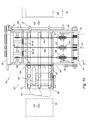
figures 7 ,8 and9 , is represented with 121 a variant of equipment for transferring sheets with change of direction, similar to theequipment 21 ofFig. 1 , including a fixedlower frame 1221 and a mobileupper frame 122h, and in which theupper frame 122h is provided for being positioned between an operative position and a position of service. In detail, thelower frame 1221 includes theback wall 25 and thesides mobile frame 122h has twosides sides frame 1221 throughpivots back section 23. In the operative position (Fig. 8 ), theframe 122h is horizontal, with the lower edges of thesides sides section 22 corresponds to the front portion of theframes Fig. 9 ), theframe 122h is inclined upwardly with respect to theframe 1221 and allows the access to theframe 1221 and the lower components. - The
equipment 121 presents areference surface 127 defined in theupper frame 122h and astop surface 128 defined in thelower frame 1221, for thesheets 26 entering along thefirst direction 27. In the operative position of theframe 122h, thereference surface 127 is horizontal, arranged between thefront section 22 and theback section 23, while thestop surface 128 is adjacent to thesection 23. Thelateral section 24r is of output for theequipment 121 and, through this lateral section, thesheets 26 emerge along asecond direction 129, right angled with respect to thefirst direction 27 and according to the transversal axis of thesheets 26. - The
equipment 121 comprises functional components equal to the functional components of theequipment 21, including theopposite output rollers 29, the members of engagement andmovement device 131,edge lifting elements 132 and anelectronic processing unit 133. - The longitudinal moving
device 131 is actuated by aninput motor 76 for moving the enteringsheets 26 along thefirst direction 27 on thereference surface 127. Theedge lifting elements 132 are arranged at the input and are associated to the movingdevice 131 for overlapping, without jamming, following entering sheets on the sheet of thereference surface 127 or on sheets overlapped of thesurface 127. Theoutput rollers 29 are kept in continuous rotation by theoutput motor 39 to engage thesheets 26 and move the sheets along thesecond direction 129. - The moving
device 131 includes, arranged in vertical, input pulleys 1371, 137cl, 137cr and 137r, front pulleys, 1381, 138c and 138r, back pulleys 1391, 139c and 139r and "O" rings or belts of movement and contrast, in detail "O" rings 141l, 141c and 141 r, between the front and back pulleys. - The input pulleys, 1371, 137cl, 137cr and 137r are keyed on a
shaft 137 of theframe 1221 and, in the operative condition of theframe 122h, these pulleys are below and in condition of tangency with respect to thereference surface 127. The front pulleys, 1381, 138c and 138r are keyed on ashaft 138 of theframe 122h and are arranged above and tangent with respect to thereference surface 127. The back pulleys 1391, 139c and 139r are coaxial with thepivots frame 122h and are supported in rotatable way by lugs of theframe 1221 adjacent to theback section 23. Thepulleys 1391, 139c and 139r are arranged above and in condition of tangency with respect to thesurface 127. - The input pulleys 1371, 137cl, 137cr and 137r are connected in the rotation with the
input motor 76 through theshaft 137 and through pulleys and a toothed belt. In the operative condition of theframe 122h, themotor 76 also actuates the front pulleys, 1381, 138c and 138r through theshaft 137 and a pair of gears including agear 1401 keyed on theshaft 137 and agear 140h keyed on theshaft 138. With reference to thefigure 7 , thepulley 1381 is arranged at the right of thepulley 1371, thepulley 138 is in central position between the pulleys 137cl and 137cr and thepulley 138r is at the left of thepulley 137r. In the condition of service of theframe 122h (Fig. 9 ), thegear 140h is disengaged from thegear 1401. - The "O" rings of movement and
contrast Figs. 7 ,8 and 8a ) are longitudinally lengthened, engaged between the front pulleys, 1381, 138c and 138r and theback pulleys 1391, 139c and 139r. The lower branches of the "O" rings 141l, 141c and 141r are adjacent to thereference surface 127 and, in the use, are designated for cooperating with thesheets 26 of thereference surface 127 for longitudinally moving the sheets along thesurface 127. - The
edge lifting elements 132 includelower contrast pulleys frame 1221, and which are designed to cooperate with the "O" rings 141l, 141c and 141 r. Eachpulley small sides 143. In the operative condition of theframe 122h, the notches of thepulley small sides 143 project of few from thesurface 127. - According to an embodiment of the invention, the
equipment 121 includestransversal guide elements 144 for transversely enteringsheets 146 from thelateral sections 241. Thesection 241 represents a transversal input, opposite to thesector 24r, of output, along thesecond direction 129, for the transfer without change of direction up to theoutput members 29. Specifically, theguide elements 144 can guidesheets 146 of large transversal dimensions, also through the space of reception between thewheels output rollers 29, for moving these sheets along thesecond direction 129. - In particular, the
transversal guide elements 144 include an upperlaminar guide 147 and a lowerlaminar guide 148. Theguide 147 is mounted on the bottom of themobile frame 122h, adjacent to the lower branches of the "O" rings, and defines thereference surface 127, while theguide 148 is mounted on an upper portion of the frame 122 parallel, in the use, with theguide 147. Thus, theguides sheets 146 underneath thereference surface 127. The laminar guides 147 and 148 include, where necessary, suitable openings to freely lodge the contrast pulleys 1421, 142c and 142r and the shapedwheels - According to the invention, the
equipment 121 can be associated or can integrate a transversal insertion device for entering thesheets 146 through thetransversal guide elements 144. - In alternative and without mechanical changes, the
equipment 121 can longitudinally introduce thesheets 26 and move the sheets along thesecond direction 129 with right angled change of direction, or receive and transversally transfer thesheets 146 without change of direction. In the condition of service of theframe 122h, the operator can access the lowerlaminar guide 148 for the removal of possible jammed sheets. - An equipment for transferring
sheets 161 according to the invention is shown inFig. 10 . Theequipment 161 is similar to theequipment 121 and integrates a transversal insertion device, represented with 162. With respect to theequipment 121, theequipment 161 has differences regarding some component of the transversal guide elements, herein represented with 163. Thedevice 162 includes asupport plate 164,transport belts 166 with upper branches slideable on theplate 164 and atransversal input motor 167 controlled by theelectronic unit 133 for the feeding of thebelts 166. - The
insertion device 162 presents a section external to theequipment 161 and an internal section. In the external section, theplate 164 and thebelts 166 transversally project from thelateral section 241 and are designed for receivingsheets 168 to be transferred without change of direction. In the internal section, theplate 164 and thebelts 166 form the lower portion of thetransversal guide elements 163. The upper portion of theelements 163 is formed by an upperlaminar guide 169 equal to theguide 147 ofFig. 8 . Thus, in the operative conditions, theplate 164 and thebelts 166 define the passage for thesheets 168 underneath the upperlaminar guide 169 between the section ofoutput 24r and the input section 24l. - The
insertion device 162 includes acounter plate 170, coupable with the external section of thesupport plate 164. In detail, thecounter plate 170 supportssmall balls 157, of known type, lodged in respective cylindrical seats above the belts 153 and spring urged against thebelts 166 to improve the transport of thesheets 146. Internally to theequipment 161, thebelts 166 allow thedevice 162 to transfer, without change of direction,sheets 168 having transversal dimensions less of the distance between thesides 24l and 24r of the frame 122l and, particularly, A5 sheets in the sense of the long edge. - On control of the
electronic processing unit 133 and without mechanical interventions, theequipment 161 can longitudinally introduce thesheets 26 and move the sheets along thesecond direction 129 with change of direction, or receive and transversally transfer thesheets 168 without change of direction. Possible jams can be removed, by accessing theplate 164 and thebelts 166 in the condition of service of theframe 122h. - For transversally transfer sheets 171 of small dimensions, the
equipment 161 can use a lengthened counter plate (not shown) which extends along the external section and the internal section of thedevice 162. The small balls 157r are also arranged along the internal section of the equipment for improving the transport of thesheets 146 along the whole extension of theplate 164 and of thebelts 166. The lengthened counter plate is coupable with thesupport plate 164 and with thebelts 166 in the condition of service of theframe 122h, while theequipment 161 is operative exclusively for the transfer of the sheets 171 without change of direction. - An equipment for transferring
sheets 176, similar to theequipment figure 11 . Theequipment 176 includes the longitudinal movingdevice 131 with "O" rings and the pulleys of lifting, theoutput rollers 29 adjacent to thesection 24r and thetransversal guide elements 144. On the contrary, theequipment 176 has a different arrangement for the members of engagement and movement, herein represented with 177 and 178. - The
members members opposite wheels opposite wheels sheets 26. The members of engagement andmovement output rollers 29 between the "O" rings and the output rollers and operate on areas of thesheets 26 adjacent to alateral edge 179. Theguide elements 144 have lateral openings for themembers sheets 146 through the space of reception between thewheels output rollers 29, for the moving of the sheets along the second direction. - In the operative conditions for the transferring of the
sheets 26, theequipments motor 76 is energized for the actuation of the "Or"ring output motor 36 is also energized and holds in continuous rotation theoutput rollers 29. In turn, the shapedwheels - A
sheet 26 entering theinput section 22 is nipped and moved by thepulleys pulleys surface 127. Then, through thesmall sides 143, the "O" rings lift the input edge of the enteringsheet 26 and allow the sheet to fall on thesurface 127 to overlap, without jamming, following entering sheets on a sheet or on preceding sheets, arranged on thesurface 127. Subsequently, the "O" rings move the sheet on thesurface 127, up to the stop against thesurface 128. Upon the passage of the edge of output in front of the sheet sensor, the processing unity energizes the actuating motor for the cyclical rotation of 180 degrees of thewheels - It occurs jointly with the input of the
input edge 52 of thesheet 26 in the space of reference between thewheels wheels equipments wheels input edge 52. During the shifting of thesheet 26 in the second direction, the equipment can receive a followingsheet 26. Theinput edge 52 of the incoming sheet is lifted for the combined action of the "O" rings 141l, 141c and 141 r and the contrast pulleys 1421, 142c and 142r. Thereafter, theinput edge 52 is depressed with partial superimposition on thesheet 26 lying on thereference surface 127 and in output. While the preceding sheet has completely abandoned the engagement with the "O" rings, the following sheet is inserted in the spaces of reception for a new activation of the actuating motor, upon the passage of the edge of output of the sheet in front of the sheet sensor, for another cycle of transferring. - In the
equipment 176, thewheels lateral edge 179 adjacent to thesection 124r. Thesheet 26 is moved in the second direction up to the engagement of thelateral edge 179 with theoutput rollers 29 for the transport in thedirection 129 and while thewheels equipment 176 is possible to receive asheet 26 during the shifting of thesheet 26 in the second direction, up to the time in which the preceding sheet has not completely abandoned the engagement with thewheels wheels 43l and 43h. - The transferring of sheets above described it is also applied to the case in which instead of a single sheet two overlapped sheets are received, as in the case in which the
equipment - Naturally, the principle of the invention remaining the same, the embodiments and the details of construction of the equipment for transferring sheets with change of direction can be widely varied with respect to what has been described and illustrated, by way of non-limitative example, without by this departing from the ambit of the present invention.
Claims (12)
- An equipment for transferring sheets (21, 121, 161, 176) with change of direction for sheets (26) entering along a first direction (27), comprising output rollers (29) for moving the sheets along a second direction (28, 129) right-angled with respect to the first direction characterized in that it comprises members of engagement and movement (33, 34; 177, 178) actuatable for engaging and moving the sheets (26) entering along the first direction (27) along the second direction up to the engagement with the output rollers (29), the said members (33, 34; 177, 178) providing a condition of reception in which define a space of reception (G) for the entering sheets (26) and a condition of engagement and movement in which engage the entered sheets and move said sheets for the engagement with the output rollers (29), and in which the members of engagement and movement (33, 34; 177, 178) return to the condition of reception upon the engagement of the entered sheet (26) with the output rollers for enabling a following sheet (26) to enter and to be moved along the first direction (27) jointly with the movement of the previous entered sheet (26) along the second direction (28, 129).
- Equipment for transferring sheets according to claim 1 characterized in that the members of engagement and movement comprise shaped rollers (33, 34; 177, 178) cyclically actuatable in the rotation between a reference position in which define the space of reception (G) and positions of engagement for engaging and moving the entered sheet (26).
- Equipment for transferring sheets according to claim 2 characterized in that said shaped rollers (33, 34; 177, 178) include a pair of opposite wheels or more pairs of opposite wheels (42l, 42h; 43l, 43h), in which at least a wheel (42l, 43l) has a depressed sector or more depressed sectors (46a, 46b) and an engagement sector or more engagement sectors (44a, 44b), and in which the depressed sector or each depressed sector is faced to the other wheel (42h, 43h) of the pair or each wheel of the pairs to define the condition of receipt, while the engagement sector or each engagement sector (44a, 44b) is designed for engaging and moving the entering sheets (26) in the condition of engagement and movement.
- Equipment for transferring sheets (21, 121, 161, 176) according to claim 3 characterized in that the said wheel and the other wheel of the pair of opposite wheels (421, 42h; 431, 43h) or of each pair of opposite wheels, comprise each one a substantially frusto-conical tapered surface (63) for the sheet in receipt, in which the other wheel of the pair of opposite wheels or the other wheels (42h, 43h) of the pairs of opposite wheels, comprise each one a high adherence coating (64), and in which said one wheel and said other wheel of the pair or of each pair of opposite wheels are in condition of synchronism.
- Equipment for transferring sheets according to claim 3 or 4 characterized in that it includes a stop surface (51) and two pairs of opposite wheels (421, 42h; 431, 43h), said pairs of wheels being in condition of synchronism and being provided for operating on two portions of an input edge (52) of the entering sheet (26) jointly with the arrival of the said input edge close or against said stop surface.
- Equipment for transferring sheets according to claim 3 or 4 characterized in that it includes a stop surface (51) and two pairs of opposite wheels (421, 42h; 431, 43h), said pairs of wheels being in condition of synchronism and being provided for operating on two portions of a lateral edge (179) of the entering sheet (26) jointly with the arrival of an input edge (52) of the entering sheet close or against said stop surface.
- Equipment for transferring sheets according to one of the preceding claims, characterized in that it defines a reference surface (48, 127), in which said members of engagement and movement (33, 34; 177, 178) are designed for receiving and moving the sheets (26) along said reference surface, and further comprising edge lifting elements (561, 56c, 56r; 1421, 142c, 142r), close to the input, to overlap, without jamming, following sheets on the sheet or on sheets overlapped on the reference surface (48, 127), elongated "O" ring or belts (541, 54c, 54r; 141l, 141c, 141 r) of movement and contrast having lower branches to cooperate with the sheets (26) of the said reference surface and in which each edge lifting element is associated to at least one lower branch of a respective "O" ring or belt of movement and contrast.
- Equipment for transferring sheets (121, 161, 176) according to one of the preceding claims characterized in that the sheets (26) entering along the first direction (27) are driven on a reference surface (127) and emerge transversely, along the second direction (129) from a given section of output (24r), and further comprising transversal guide elements (144) for guiding sheets (146, 168) entering transversally, along the second direction (129), from a transversal input section (241) of the equipment opposite to the section of output (24r), adjacently and underneath the reference surface (127) and up to the output members (29).
- Equipment for transferring sheets (21) according to claim 2 or 3 or 4 characterized in that the output rollers (29, 94) are arranged at the two sides (241, 24r) of the equipment and have sense of rotation opposed for transferring the sheets (26) through a side (241) of the equipment, in association with a given sense of rotation of the shaped rollers or through a side (24r) of the equipment opposed to said a side (241), in association with a sense of rotation of the said shaped rollers, opposite to the said given sense of rotation of the rollers.
- An equipment for transferring sheets (21, 121, 161, 176) with change of direction for sheets (26) entering along a first direction (27), comprising output rollers (29) for moving the sheets (26) along a second direction (28, 129) right angled with respect to the first direction (27), characterized in that
the said equipment comprises an actuating motor (36) and a pair or more pairs of cyclically actuatable opposite wheels (421, 42h; 431, 43h) to engage and move along the second direction (28, 129), up to the engagement with the output rollers, the sheets (26) entering along the first direction, a sheet sensor (35), arranged upstream of the opposite wheels and an electronic processing unit (38), in which,
at least a wheel (421, 431) of pair or each pair of wheels has one or more sectors (44a, 44b) provided for engagement with the other wheel (42h, 43h) and one or more depressed sectors (46a, 46b), and in which
the depressed sector or one of the depressed sectors is faced to the other wheel of the pair, in a reference position, to define a condition of receipt for the entering sheets (26), while the sector provided for engagement or each sector provided for engagement is designed to engage and move the sheets (26) in the condition of engagement and movement,
the electronic processing unit responding to a signal or signals of the said sensor for controlling the actuating motor (36) in order to actuate said at least a wheel (421, 431) from the reference position to positions of engagement and movement and return to the reference position, and
each sheet (26) entering along the first direction (27) being moved up to the engagement with the output rollers (29) by the sector (44a, 44b) or the sectors provided for engagement, while a following sheet (26) being allowed to enter and to be moved along a first direction (27) up to the space defined by the depressed sectors for a new transferring of the sheets, jointly with the movement along the second direction (28, 129) of a sheet engaged by the output rollers (29). - Equipment for transferring sheets (121, 161, 176) with change of direction, comprising an input section (22), of reception of sheets (26) entering along a first direction (27), output rollers (29) for moving the sheets (26) along a second direction (129), right angled with respect to the first direction and control and actuation means (133; 33, 34) for putting in engagement with the output rollers the sheets (26) entered along the first direction (27), the said equipment being characterized in that it comprises:"O" ring (141l, 141c, 141 r) of movement and contrast, lengthened along the first direction (27) and having a lower branch tangent to a reference surface (127) for engaging the entering sheets (26) and moving the entering sheets along the reference surface; andmembers of engagement and movement (33, 34) of the said control and actuation means (33, 34; 36);said members of engagement and movement being operative in proximity of an edge (52, 179) of the sheets (26) arranged on said reference surface (127), for moving said sheets (26) up to the engagement with the output rollers (29).
- Equipment for transferring sheets (121, 161, 176) with change of direction for sheets (26), entering longitudinally along a first direction (27) and comprising output members (29), adjacent to a section of output (24r) for moving the sheets (26) along a second direction (129), right angled with respect to the first direction, the said equipment being characterized in that it comprises:a moving device (76; 141l, 141c, 141r) for longitudinally moving the longitudinally entering sheets (26) on a reference surface (127);members of engagement and movement (33, 34) for putting the longitudinally entered sheets (26) in engagement with the output members (29) along the reference surface (127); andtransversal guide elements (144) for guiding, along the second direction (29), transversely entering sheets (146) entering transversely from an input section (241) of the equipment, opposite to the section of output (24r), adjacently and underneath the reference surface (127) and up to the output members (29).
Applications Claiming Priority (1)
| Application Number | Priority Date | Filing Date | Title |
|---|---|---|---|
| IT000280A ITTO20070280A1 (en) | 2007-04-20 | 2007-04-20 | EQUIPMENT FOR SHEET TRANSFER WITH CHANGE OF DIRECTION |
Publications (2)
| Publication Number | Publication Date |
|---|---|
| EP1982940A2 true EP1982940A2 (en) | 2008-10-22 |
| EP1982940A3 EP1982940A3 (en) | 2011-12-07 |
Family
ID=39639239
Family Applications (1)
| Application Number | Title | Priority Date | Filing Date |
|---|---|---|---|
| EP08103625A Withdrawn EP1982940A3 (en) | 2007-04-20 | 2008-04-18 | Equipment for transferring sheets with change of direction |
Country Status (3)
| Country | Link |
|---|---|
| US (1) | US7934721B2 (en) |
| EP (1) | EP1982940A3 (en) |
| IT (1) | ITTO20070280A1 (en) |
Families Citing this family (5)
| Publication number | Priority date | Publication date | Assignee | Title |
|---|---|---|---|---|
| US7841594B2 (en) * | 2008-09-30 | 2010-11-30 | Pitney Bowes Inc. | Apparatus for altering the orientation and/or direction of sheet material in mailpiece fabrication systems |
| US8727099B2 (en) | 2010-05-24 | 2014-05-20 | Usnr/Kockums Cancar Company | Tapered roll feed |
| US20130104417A1 (en) * | 2011-11-02 | 2013-05-02 | Shenzhen China Star Optoelectronics Technology Co. , Ltd. | Drying device for glass substrate with alignment liquid sprayed thereon and conveying apparatus with the same |
| JP5936173B2 (en) * | 2011-12-28 | 2016-06-15 | 株式会社リコー | Sheet material position correction apparatus and image forming apparatus |
| CA2834521C (en) | 2012-11-21 | 2015-03-10 | Usnr/Kockums Cancar Company | Systems, methods and apparatuses for changing the direction/speed of a workpiece |
Citations (1)
| Publication number | Priority date | Publication date | Assignee | Title |
|---|---|---|---|---|
| US20030137100A1 (en) * | 2002-01-18 | 2003-07-24 | Elton Hsieh | Feeding direction altering device for documents |
Family Cites Families (3)
| Publication number | Priority date | Publication date | Assignee | Title |
|---|---|---|---|---|
| US4871163A (en) * | 1986-06-09 | 1989-10-03 | Savin Corporation | Paper control gate |
| US5205551A (en) * | 1989-03-20 | 1993-04-27 | Canon Kabushiki Kaisha | Apparatus for transporting sheet |
| JPH05254641A (en) * | 1992-03-12 | 1993-10-05 | Suzuki Motor Corp | Transport direction changing device for work |
-
2007
- 2007-04-20 IT IT000280A patent/ITTO20070280A1/en unknown
-
2008
- 2008-04-18 EP EP08103625A patent/EP1982940A3/en not_active Withdrawn
- 2008-04-18 US US12/105,783 patent/US7934721B2/en not_active Expired - Fee Related
Patent Citations (1)
| Publication number | Priority date | Publication date | Assignee | Title |
|---|---|---|---|---|
| US20030137100A1 (en) * | 2002-01-18 | 2003-07-24 | Elton Hsieh | Feeding direction altering device for documents |
Also Published As
| Publication number | Publication date |
|---|---|
| US7934721B2 (en) | 2011-05-03 |
| US20080284089A1 (en) | 2008-11-20 |
| ITTO20070280A1 (en) | 2008-10-21 |
| EP1982940A3 (en) | 2011-12-07 |
Similar Documents
| Publication | Publication Date | Title |
|---|---|---|
| JP2590477B2 (en) | Paper transport direction change device | |
| EP1982940A2 (en) | Equipment for transferring sheets with change of direction | |
| CA2422993C (en) | Device for turning piles of sheets-like material | |
| US7731188B2 (en) | Sheet registration system with auxiliary nips | |
| US7631744B2 (en) | Device for transporting printed products | |
| EP2796253B1 (en) | Punching machine | |
| US9731430B2 (en) | Transversal cutting equipment for sheets separable from overlapped continuous forms | |
| US4546871A (en) | Gap maker | |
| CN104093646B (en) | Batch conveyor unit for processing units of plate-like components in packaging lines | |
| EP0789664B1 (en) | Turnover-sequencer staging apparatus and method | |
| US20050263956A1 (en) | Double-sided document transport device | |
| US4607833A (en) | Demand document feeder | |
| JP2007076774A5 (en) | ||
| JP2008169044A (en) | Apparatus and method for aligning a stack of sequentially stacked sheets | |
| US10239722B2 (en) | Punching system | |
| US5727923A (en) | Collecting device for sheets | |
| EP1870360B1 (en) | Method and buffer station for buffering documents | |
| CA2519171C (en) | Laser inscribing station for credit cards | |
| CN103373637A (en) | Method for folding and buckle plate folding machine | |
| CN112758750B (en) | Paper detection device and paper detection method | |
| EP0343001B1 (en) | Multiple stage dispenser | |
| EP2824051B1 (en) | Sheet folding device | |
| EP0074742A1 (en) | Apparatus for handling single sheets delivered in succession | |
| JP2003146484A (en) | Sheet carrier | |
| JPS6151445A (en) | Sheet matching device |
Legal Events
| Date | Code | Title | Description |
|---|---|---|---|
| PUAI | Public reference made under article 153(3) epc to a published international application that has entered the european phase |
Free format text: ORIGINAL CODE: 0009012 |
|
| AK | Designated contracting states |
Kind code of ref document: A2 Designated state(s): AT BE BG CH CY CZ DE DK EE ES FI FR GB GR HR HU IE IS IT LI LT LU LV MC MT NL NO PL PT RO SE SI SK TR |
|
| AX | Request for extension of the european patent |
Extension state: AL BA MK RS |
|
| RIC1 | Information provided on ipc code assigned before grant |
Ipc: B65H 29/66 20060101ALI20110601BHEP Ipc: B65G 47/54 20060101ALI20110601BHEP Ipc: B65H 29/12 20060101AFI20080801BHEP |
|
| PUAL | Search report despatched |
Free format text: ORIGINAL CODE: 0009013 |
|
| AK | Designated contracting states |
Kind code of ref document: A3 Designated state(s): AT BE BG CH CY CZ DE DK EE ES FI FR GB GR HR HU IE IS IT LI LT LU LV MC MT NL NO PL PT RO SE SI SK TR |
|
| AX | Request for extension of the european patent |
Extension state: AL BA MK RS |
|
| RIC1 | Information provided on ipc code assigned before grant |
Ipc: B65H 29/66 20060101ALI20111103BHEP Ipc: B65H 29/12 20060101AFI20111103BHEP Ipc: B65G 47/54 20060101ALI20111103BHEP |
|
| 17P | Request for examination filed |
Effective date: 20120531 |
|
| 17Q | First examination report despatched |
Effective date: 20120618 |
|
| AKX | Designation fees paid |
Designated state(s): AT BE BG CH CY CZ DE DK EE ES FI FR GB GR HR HU IE IS IT LI LT LU LV MC MT NL NO PL PT RO SE SI SK TR |
|
| R17P | Request for examination filed (corrected) |
Effective date: 20120531 |
|
| STAA | Information on the status of an ep patent application or granted ep patent |
Free format text: STATUS: THE APPLICATION IS DEEMED TO BE WITHDRAWN |
|
| 18D | Application deemed to be withdrawn |
Effective date: 20180410 |