EP1982939A1 - Web material winding machine - Google Patents
Web material winding machine Download PDFInfo
- Publication number
- EP1982939A1 EP1982939A1 EP07007747A EP07007747A EP1982939A1 EP 1982939 A1 EP1982939 A1 EP 1982939A1 EP 07007747 A EP07007747 A EP 07007747A EP 07007747 A EP07007747 A EP 07007747A EP 1982939 A1 EP1982939 A1 EP 1982939A1
- Authority
- EP
- European Patent Office
- Prior art keywords
- core tube
- roller
- web material
- winding machine
- winding
- Prior art date
- Legal status (The legal status is an assumption and is not a legal conclusion. Google has not performed a legal analysis and makes no representation as to the accuracy of the status listed.)
- Granted
Links
Images


Classifications
-
- B—PERFORMING OPERATIONS; TRANSPORTING
- B65—CONVEYING; PACKING; STORING; HANDLING THIN OR FILAMENTARY MATERIAL
- B65H—HANDLING THIN OR FILAMENTARY MATERIAL, e.g. SHEETS, WEBS, CABLES
- B65H19/00—Changing the web roll
- B65H19/22—Changing the web roll in winding mechanisms or in connection with winding operations
- B65H19/2238—The web roll being driven by a winding mechanism of the nip or tangential drive type
- B65H19/2269—Cradle
-
- B—PERFORMING OPERATIONS; TRANSPORTING
- B65—CONVEYING; PACKING; STORING; HANDLING THIN OR FILAMENTARY MATERIAL
- B65H—HANDLING THIN OR FILAMENTARY MATERIAL, e.g. SHEETS, WEBS, CABLES
- B65H19/00—Changing the web roll
- B65H19/22—Changing the web roll in winding mechanisms or in connection with winding operations
- B65H19/26—Cutting-off the web running to the wound web roll
- B65H19/267—Cutting-off the web running to the wound web roll by tearing or bursting
-
- B—PERFORMING OPERATIONS; TRANSPORTING
- B65—CONVEYING; PACKING; STORING; HANDLING THIN OR FILAMENTARY MATERIAL
- B65H—HANDLING THIN OR FILAMENTARY MATERIAL, e.g. SHEETS, WEBS, CABLES
- B65H19/00—Changing the web roll
- B65H19/22—Changing the web roll in winding mechanisms or in connection with winding operations
- B65H19/28—Attaching the leading end of the web to the replacement web-roll core or spindle
- B65H19/283—Attaching the leading end of the web to the replacement web-roll core or spindle by applying adhesive to the core
-
- B—PERFORMING OPERATIONS; TRANSPORTING
- B65—CONVEYING; PACKING; STORING; HANDLING THIN OR FILAMENTARY MATERIAL
- B65H—HANDLING THIN OR FILAMENTARY MATERIAL, e.g. SHEETS, WEBS, CABLES
- B65H19/00—Changing the web roll
- B65H19/22—Changing the web roll in winding mechanisms or in connection with winding operations
- B65H19/29—Securing the trailing end of the wound web to the web roll
-
- B—PERFORMING OPERATIONS; TRANSPORTING
- B65—CONVEYING; PACKING; STORING; HANDLING THIN OR FILAMENTARY MATERIAL
- B65H—HANDLING THIN OR FILAMENTARY MATERIAL, e.g. SHEETS, WEBS, CABLES
- B65H2301/00—Handling processes for sheets or webs
- B65H2301/40—Type of handling process
- B65H2301/41—Winding, unwinding
- B65H2301/414—Winding
- B65H2301/4144—Finishing winding process
- B65H2301/41441—Finishing winding process and blocking outer layers against falling apart
- B65H2301/41442—Specified by the sealing medium sealing used
- B65H2301/414421—Glue or hot-melt
-
- B—PERFORMING OPERATIONS; TRANSPORTING
- B65—CONVEYING; PACKING; STORING; HANDLING THIN OR FILAMENTARY MATERIAL
- B65H—HANDLING THIN OR FILAMENTARY MATERIAL, e.g. SHEETS, WEBS, CABLES
- B65H2301/00—Handling processes for sheets or webs
- B65H2301/40—Type of handling process
- B65H2301/41—Winding, unwinding
- B65H2301/417—Handling or changing web rolls
- B65H2301/418—Changing web roll
- B65H2301/4181—Core or mandrel supply
- B65H2301/41814—Core or mandrel supply by container storing cores and feeding through wedge-shaped slot or elongated channel
-
- B—PERFORMING OPERATIONS; TRANSPORTING
- B65—CONVEYING; PACKING; STORING; HANDLING THIN OR FILAMENTARY MATERIAL
- B65H—HANDLING THIN OR FILAMENTARY MATERIAL, e.g. SHEETS, WEBS, CABLES
- B65H2408/00—Specific machines
- B65H2408/20—Specific machines for handling web(s)
- B65H2408/23—Winding machines
- B65H2408/235—Cradles
Definitions
- the present invention relates to a winding machine, and more particularly to a winding machine for winding a web material around a core tube to producing a wound roll thereof.
- Winding machine is commonly used in the pulp and paper industry and textile industry for producing smaller diameter logs or rolls of web material from large diameter parent rolls.
- winding machines are used in the paper converting industry to produce rolls of toilet paper, kitchen towel and the like.
- a conventional winding machine is provided with a presser which has a surface with high coefficient of friction and which exerts a pressure to impede the forward movement of the web material. This results to the tearing off of the web material.
- a severing means having sharp, saw-toothed blades is used to sever the web material.
- U.S. Patent No. 5,979,818 discloses a rewinding machine for the formation of logs of web materials.
- a material-serving device is provided for severing the web material when the winding of web material is completed.
- Either the presser or severing means has to work with a stoke and timing control device, such as an automatic timing control roller, an automatic timing control cam or linkage assembly, etc.
- the presser is driven to act on the web material at a predetermined serving timing by the stoke and timing control device, such as at pressing timing or clipping timing.
- a stoke and timing control device such as an automatic timing control roller, an automatic timing control cam or linkage assembly, etc.
- the presser is driven to act on the web material at a predetermined serving timing by the stoke and timing control device, such as at pressing timing or clipping timing.
- a primary object of the present invention is to provide a web material winding device which is able to tear a web material by arranging a transporting passage.
- the transporting passage has a dimension that is slightly smaller than the diameter of the core tube.
- the new core tube conveying on the transporting passage presses on the web material, generating an interference to the speed of the web material and causing the tearing of the web material. No presser or severing means is needed for severing the web material.
- Another object of the present invention is to provide a winding machine that tears the web material to complete a roll whenever a new core tube is delivered to the transporting passage. No time control device is needed for controlling the tearing of the web material.
- the winding machine comprises a core tube storage tank, a guiding unit, a transmission means, a web material feeding assembly, a gripping assembly and a second gluing mechanism.
- a core tube is glued with initial glue and conveyed from the guiding unit to the transmission means. Meanwhile, the web material is fed by the web material feeding assembly to the transmission means at a normal speed.
- the transmission means pushes the core tube to move through a transporting passage to the gripping assembly and the web material is stuck to the core tube. The web material winds around the core tube at the winding region.
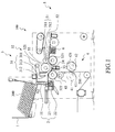
- FIG. 1 is the schematic view of a web material winding machine constructed in accordance with a preferred embodiment of the present invention.
- a web material winding machine 100 is adapted to wind a web material 200 to a core tube 300.
- the winding machine 100 includes a core tube storage tank 1, a guiding unit 2, a transmission means 3, a web material feeding assembly 4, a gripping assembly 5 and a second gluing mechanism 6.
- the core tube storage tank 1 contains with a plurality of core tubes 300 and has an opening (not labeled) at the right bottom corner for supplying the core tubes 300.
- the guiding unit 2 communicates with the opening of the core tube storage tank 1 and includes a guiding passage 21, a first gluing mechanism 22 and a pushing mechanism 23.
- the first gluing mechanism 22 contains glue.
- the guiding passage 21 connects the core tube storage tank 1 to the pushing mechanism 23. Through the guiding passage 21, the core tube 300 is conveyed from the core tube storage tank 1 to the platform of the pushing mechanism 23. Then, the first gluing mechanism 22 applies an initial glue to the core tube 300 on the platform of the pushing mechanism 23.
- the pushing mechanism 23 has a retractable arm that pushes the glued core tube 300 along the platform to the transmission means 3.
- the transmission means 3 includes an oscillable feeding arm 31, a roller assembly 32 and a rolling guiding mechanism 33.
- the feeding arm 31 is located above the pushing mechanism 23 and has a fixed end 311, a pushing end 312 and a pushing roller 313.
- the feeding arm 31 is pivoted at the fixed end 311 such that the pushing end 312 is movable along a first oscillating orbit I as shown in Fig. 3 .
- the pushing roller 313 is mounted to the pushing end 312 of the feeding arm 31 for pushing the core tube 300 forward along the oscillating orbit I.
- the roller assembly 32 includes a first roller 321, a second roller 322 and a third roller 323.
- the first roller 321 is located nearby the feeding arm 31.
- the second roller 322 and the third roller 323 are below the first roller 321 and are respectively positioned at the two sides of the first roller 321.
- a clearance is formed between the first roller 321 and the second roller 322.
- the clearance is on the oscillating orbit I.
- a clearance is also formed between the second roller 322 and the third roller 323.
- the rolling guiding mechanism 33 is arranged between the first roller 321 and the second roller 322, forming a continuous curved surface between the first roller 321 and the second roller 322.
- the curved surface and the first roller 321 defines a transporting passage 34 for conveying the core tube 300 therethrough.
- the transporting passage 34 is designed to have a width slightly smaller than the diameter of the core tube 300. Therefore, when the core tube 300a is conveyed along the transporting passage 34, the core tube 300a is squeezed to deform slightly, turning into oval shape.
- the web material 200 is fed through the web material feeding assembly 4 to the roller assembly 32.
- the web material feeding assembly 4 includes a stationary counter roller 41, a perforation roller 42 and a feeding roller 43.
- the counter roller 41 is provided with a counter blade 411
- the perforation roller 42 is provided with a plurality of blades 421 regularly spaced at the periphery of the perforation roller 42.
- the counter blade 411 of the counter roller 41 operates in coordination with the blades 421 of the perforation roller 42.
- the web material 200 is conveyed to the feeding roller 43 through a passage between the counter roller 41 and the perforation roller 42.
- the blades 421 of the perforation roller 42 pierce through the web material 200 to the counter blade 411 of the counter roller 41, forming a line of perforations across the web material 200.
- the perforation roller 42 is driven to rotate at a predetermined speed such that a perforation line is produced at the web material 200 for each predetermined distance.
- the feeding roller 43 is located below the second roller 322 for feeding the web material 200 to the second roller 322.
- the gripping assembly 5 includes an oscillable gripping arm 51 and a gripping roller 52.
- the gripping arm 51 has a fixed end 511 and a gripping end 512.
- the gripping end 512 is pivoted at the fixed end 511, such that the gripping end 512 is movable along a second oscillating orbit II as shown in Fig. 3 .
- the gripping roller 52 is mounted to the gripping end 512 and is adjacent to the first roller 321 and above the third roller 323 for gripping the working core tube 300a.
- a winding region 53 is defined among the first roller 321, the third roller 323 and the gripping roller 52.
- FIG. 2 is an exploded perspective view showing a second gluing mechanism of the web material winding machine of Fig. 1 .
- the second gluing mechanism 6 is arranged adjacent to the third roller 323 and tilts downward.
- the second gluing mechanism 6 includes a cover plate 61, an injector 62, a glue supply 63 and a casing 64.
- the cover plate 61, the injector 62 and glue supply 63 are aligned with each other and are piled together from top to bottom in sequence.
- the casing 64 is fastened to the plate 61 by screws for accommodation and protection of the injector 62 and glue supply 63 therebetween.
- the cover plate 61 is perforated with a plurality of apertures 611.
- the injector 62 is provided with a support base 621 and a plurality of injecting needles 622. Each of the injecting needles 622 aligns with an aperture 611 located above.
- the glue supply 63 comprises a support base 631, a plurality of tubes 632 and a plurality of ducts 633.
- the tubes 632 are supported on the support base 631.
- Each of the tubes 632 is connected with a duct 633 which is aligned with an injecting needle 622 above the glue supply 63.
- the tubes 632 contain glue and supply the glue through the ducts 633 to the injecting needles 622.
- FIG. 3 is a schematic view showing the delivery of core tubes to the guiding unit of the web material winding machine of Fig. 1 .
- the core tubes 300 are delivered one by one from the core tube storage tank 1 through the guiding passage 21 to the platform of the pushing mechanism 23.
- the first gluing mechanism 22 of the guiding unit 2 applies initial glue to the core tube 300.
- Fig. 4 is a schematic view showing that the core tube is conveyed to the transmission means 3 of the web material winding machine.
- the glued core tube 300 is pushed forward by the retractable arm of the pushing mechanism 23 along the platform to the transmission means 3.
- the web material 200 is conveyed through the web material feeding assembly 4 to the roller assembly 32.
- the blades 421 of the perforation roller 42 works with the counter blade 411 of the counter roller 41, producing a line of perforations across the web material 200.
- Fig. 5 is a schematic view showing that the core tube is conveyed to the transporting passage of the transmission means.
- the feeding arm 31 oscillates around the fixed end 311, and accordingly, the pushing end 312 moves along the first oscillating orbit I. It can be seen from Fig. 5 that the pushing roller 313 pushes the core tube 300 to displace into the transporting passage 34.
- the transporting passage 34 has a width slightly smaller than the diameter of the core tube 300. Therefore, when the core tube 300a is conveyed along the transporting passage 34, the core tube 300a is squeezed to oval shape.
- Fig. 7 is a schematic view showing that the working core tube 300a reaches the winding region 53 of the gripping assembly 5 and is gripped by the gripping arm 51. At the same time, the feeding arm 31 swings back to its original position.
- the working core tube 300a is driven to rotate to wind the web material 200 at the winding region 53.
- the first gluing mechanism 22 applies initial glue to a new core tube 300.
- the operation of the guiding unit 2 is controlled by a control means.
- the control means may be any conventional control device that can be preset with various operation parameters, e.g. the timing of release of core tube from the guiding unit 2.
- Fig. 9 is a schematic view showing the new core tube 300 is conveyed to the transmission means 3.
- the glued new core tube 300 is pushed forward by the arm of the pushing mechanism 23 along the platform to the transmission means 3.
- the working core tube 300a at the winding region 53 keeps on winding at the normal speed.
- Fig. 10 is similar to Fig. 3 .
- the new core tube 300 is pushed to enter the transporting passage 34 by the feeding arm 31. Once entering the passage 34, the core tube 300 contacts the web material 200 and sticks the web material 200 by the initial glue, forming a new working core tube 300a.
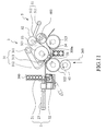
- Fig. 11 a schematic view showing the new core tube presses on the web material feeding to the winding core tube.
- the new core tube 300a moves through the transporting passage 34 and is squeezed to become oval shape.
- the new core tube 300a presses on the web material 200, and therefore, the new core tube 300a interferes the movement of the web material 200. This interference action slows down the feeding speed of the web material 200 or even stops the feeding of the web material 200 to the working core tube 300a.
- the working core tube 300a at the winding region 53 keeps rotation at its normal speed.
- Fig. 12 is a schematic view showing the tearing of the web material.
- the pulling force causes the web material 200 to tear along the perforation line.
- the winding of the working core tube 300a is completed and a roll 400 is produced.
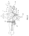
- Fig. 13 shows that the roll 400 leaves the winding region 53 and the new core tube 300a is conveyed to the winding region 53.
- the second gluing mechanism 6 tilts downward, the roll 400 leaves the winding region 53 and rolls across the cover plate 61 of the second gluing mechanism 6.
- the second gluing mechanism 6 injects tail glue through the apertures 611 to the web material 200 of the roll 400.
- the web material 200 is adhered by the tail glue to the roll 400.
- the processing to the roll 400 is accomplished.
- the injection of the final glue by the second gluing mechanism is also controlled by the control means. Meanwhile, the new working core tube 300a is conveyed to the winding region 53.
- the control means drives the injector 62 and the glue supply 63 to lift up such that the injecting needles 622 reaches the apertures 611 and are close to the roll 400, and injecting needles 622 inject tail glue to the roll 400.
- the injector 62 and the glue supply 63 returns to its original position.
- the upward and downward movement of the injector 62 and the glue supply 63 are achieved by a retractable lifting device.
- the lifting device may comprise spiral pins, springs or other effective elements.
- the tearing of web material is achieved by the interference of the new core tube to the working core tube.
- the winding machine tears the web material whenever a new core tube is delivered to the transporting passage.
- No presser or severing means is required.
- no time control device is needed for controlling the working of the presser.
- the manufacture, operation and maintenance of the winding machine are simplified. It significantly reduces the manufacture, operation and maintenance cost.
Landscapes
- Replacement Of Web Rolls (AREA)
Abstract
Description
- The present invention relates to a winding machine, and more particularly to a winding machine for winding a web material around a core tube to producing a wound roll thereof.
- Winding machine is commonly used in the pulp and paper industry and textile industry for producing smaller diameter logs or rolls of web material from large diameter parent rolls. For example, winding machines are used in the paper converting industry to produce rolls of toilet paper, kitchen towel and the like.
- A conventional winding machine is provided with a presser which has a surface with high coefficient of friction and which exerts a pressure to impede the forward movement of the web material. This results to the tearing off of the web material. Alternatively, a severing means having sharp, saw-toothed blades is used to sever the web material. An example is shown in
U.S. Patent No. 5,979,818 which discloses a rewinding machine for the formation of logs of web materials. In the patent, a material-serving device is provided for severing the web material when the winding of web material is completed. - Either the presser or severing means has to work with a stoke and timing control device, such as an automatic timing control roller, an automatic timing control cam or linkage assembly, etc. The presser is driven to act on the web material at a predetermined serving timing by the stoke and timing control device, such as at pressing timing or clipping timing. Such a design inevitably increases the manufacture cost and complicates the control system.
- Moreover, it is necessary to precisely control the timing or stoke for the winding device. Once the presser is damaged, the stoke is offset out of a preset stoke, or the timing control is not correct and lapses from the preset timing, the web material is cut at the improper time and it would result to poor quality of the logs.
- Thus, it is desired to provide a winding machine that does not require the installation of any pressing means to simplify the control of the winding machine and the manufacture cost.
- A primary object of the present invention is to provide a web material winding device which is able to tear a web material by arranging a transporting passage. The transporting passage has a dimension that is slightly smaller than the diameter of the core tube. The new core tube conveying on the transporting passage presses on the web material, generating an interference to the speed of the web material and causing the tearing of the web material. No presser or severing means is needed for severing the web material.
- Another object of the present invention is to provide a winding machine that tears the web material to complete a roll whenever a new core tube is delivered to the transporting passage. No time control device is needed for controlling the tearing of the web material.
- To fulfill the above objects, the present invention provides a web material winding machine. The winding machine comprises a core tube storage tank, a guiding unit, a transmission means, a web material feeding assembly, a gripping assembly and a second gluing mechanism. A core tube is glued with initial glue and conveyed from the guiding unit to the transmission means. Meanwhile, the web material is fed by the web material feeding assembly to the transmission means at a normal speed. The transmission means pushes the core tube to move through a transporting passage to the gripping assembly and the web material is stuck to the core tube. The web material winds around the core tube at the winding region. When the winding is nearly completed, a new core tube is conveyed to the transporting passage and interferes the speed of web material, causing the web material to tear along the perforation line. A tail glue is applied to the completed core tube by the second gluing mechanism and a roll is produced.
- The structure and the technical means adopted by the present invention to achieve the above and other objects can be best understood by referring to the following detailed description of the preferred embodiments and the accompanying drawings, wherein:
-
Fig. 1 is a schematic view of a web material winding machine constructed in accordance with a preferred embodiment of the present invention; -
Fig. 2 is an exploded perspective view showing a second gluing mechanism of the web material winding machine ofFig. 1 ; -
Fig. 3 is a schematic view showing the delivery of core tubes to a guiding unit of the web material winding machine ofFig. 1 ; -
Fig. 4 is a schematic view showing that a core tube is conveyed to a transmission means of the web material winding machine; -
Fig. 5 is a schematic view showing that the core tube is conveyed to a transporting passage of the transmission means; -
Fig. 6 is a schematic view showing that a web material is stuck to the core tube; -
Fig. 7 is a schematic view showing a working core tube is gripped by a gripping arm; -
Fig. 8 is a schematic view showing that the working core tube is proceeding winding work in the winding region; -
Fig. 9 is a schematic view showing that the winding of the working core tube is nearly completed and a new core tube is conveyed to the transmission means; -
Fig. 10 is a schematic view showing that the web material is stuck on the new core tube that enters the transporting passage; -
Fig. 11 is a schematic view showing that the new working core tube presses on the web material; -
Fig. 12 is a schematic view showing the tearing of web material; and -
Fig. 13 is a schematic view showing that the roll leaves the winding region and the new core tube is conveyed to the winding region. - With reference to the drawings and in particular to
Fig. 1 which is the schematic view of a web material winding machine constructed in accordance with a preferred embodiment of the present invention. A webmaterial winding machine 100 is adapted to wind aweb material 200 to acore tube 300. Thewinding machine 100 includes a core tube storage tank 1, a guidingunit 2, a transmission means 3, a webmaterial feeding assembly 4, a gripping assembly 5 and asecond gluing mechanism 6. - The core tube storage tank 1 contains with a plurality of
core tubes 300 and has an opening (not labeled) at the right bottom corner for supplying thecore tubes 300. The guidingunit 2 communicates with the opening of the core tube storage tank 1 and includes a guidingpassage 21, afirst gluing mechanism 22 and apushing mechanism 23. Thefirst gluing mechanism 22 contains glue. The guidingpassage 21 connects the core tube storage tank 1 to thepushing mechanism 23. Through the guidingpassage 21, thecore tube 300 is conveyed from the core tube storage tank 1 to the platform of thepushing mechanism 23. Then, thefirst gluing mechanism 22 applies an initial glue to thecore tube 300 on the platform of thepushing mechanism 23. Thepushing mechanism 23 has a retractable arm that pushes the gluedcore tube 300 along the platform to the transmission means 3. - The transmission means 3 includes an
oscillable feeding arm 31, aroller assembly 32 and a rollingguiding mechanism 33. Thefeeding arm 31 is located above thepushing mechanism 23 and has a fixedend 311, a pushingend 312 and a pushingroller 313. Thefeeding arm 31 is pivoted at the fixedend 311 such that the pushingend 312 is movable along a first oscillating orbit I as shown inFig. 3 . The pushingroller 313 is mounted to the pushingend 312 of thefeeding arm 31 for pushing thecore tube 300 forward along the oscillating orbit I. - The
roller assembly 32 includes afirst roller 321, asecond roller 322 and athird roller 323. Thefirst roller 321 is located nearby thefeeding arm 31. Thesecond roller 322 and thethird roller 323 are below thefirst roller 321 and are respectively positioned at the two sides of thefirst roller 321. A clearance is formed between thefirst roller 321 and thesecond roller 322. The clearance is on the oscillating orbit I. A clearance is also formed between thesecond roller 322 and thethird roller 323. - The rolling
guiding mechanism 33 is arranged between thefirst roller 321 and thesecond roller 322, forming a continuous curved surface between thefirst roller 321 and thesecond roller 322. The curved surface and thefirst roller 321 defines a transportingpassage 34 for conveying thecore tube 300 therethrough. - In order to strengthen the interference action of the
new core tube 300 to the feeding ofweb material 200 to the workingcore tube 300a (as shown inFig. 5 ), the transportingpassage 34 is designed to have a width slightly smaller than the diameter of thecore tube 300. Therefore, when thecore tube 300a is conveyed along the transportingpassage 34, thecore tube 300a is squeezed to deform slightly, turning into oval shape. - The
web material 200 is fed through the webmaterial feeding assembly 4 to theroller assembly 32. The webmaterial feeding assembly 4 includes astationary counter roller 41, aperforation roller 42 and a feedingroller 43. Thecounter roller 41 is provided with acounter blade 411, and theperforation roller 42 is provided with a plurality ofblades 421 regularly spaced at the periphery of theperforation roller 42.. Thecounter blade 411 of thecounter roller 41 operates in coordination with theblades 421 of theperforation roller 42. During operation, theweb material 200 is conveyed to the feedingroller 43 through a passage between thecounter roller 41 and theperforation roller 42. Meanwhile, theblades 421 of theperforation roller 42 pierce through theweb material 200 to thecounter blade 411 of thecounter roller 41, forming a line of perforations across theweb material 200. Theperforation roller 42 is driven to rotate at a predetermined speed such that a perforation line is produced at theweb material 200 for each predetermined distance. The feedingroller 43 is located below thesecond roller 322 for feeding theweb material 200 to thesecond roller 322. - The gripping assembly 5 includes an oscillable
gripping arm 51 and agripping roller 52. Thegripping arm 51 has a fixedend 511 and agripping end 512. Thegripping end 512 is pivoted at thefixed end 511, such that thegripping end 512 is movable along a second oscillating orbit II as shown inFig. 3 . The grippingroller 52 is mounted to thegripping end 512 and is adjacent to thefirst roller 321 and above thethird roller 323 for gripping the workingcore tube 300a. A windingregion 53 is defined among thefirst roller 321, thethird roller 323 and the grippingroller 52. - Please refer to
Fig. 2 , which is an exploded perspective view showing a second gluing mechanism of the web material winding machine ofFig. 1 . Thesecond gluing mechanism 6 is arranged adjacent to thethird roller 323 and tilts downward. Thesecond gluing mechanism 6 includes acover plate 61, aninjector 62, a glue supply 63 and acasing 64. Thecover plate 61, theinjector 62 and glue supply 63 are aligned with each other and are piled together from top to bottom in sequence. Thecasing 64 is fastened to theplate 61 by screws for accommodation and protection of theinjector 62 and glue supply 63 therebetween. - The
cover plate 61 is perforated with a plurality ofapertures 611. Theinjector 62 is provided with asupport base 621 and a plurality of injectingneedles 622. Each of the injecting needles 622 aligns with anaperture 611 located above. The glue supply 63 comprises asupport base 631, a plurality of tubes 632 and a plurality ofducts 633. The tubes 632 are supported on thesupport base 631. Each of the tubes 632 is connected with aduct 633 which is aligned with an injectingneedle 622 above the glue supply 63. The tubes 632 contain glue and supply the glue through theducts 633 to the injecting needles 622. When theroll 400 rolls (as shown inFig. 9 ) across thecover plate 61, theinjector 62 injects tail glue through theapertures 611 to theweb material 200 of theroll 400. - Please refer to
Figs. 3 to 13 that show an operation of the web material winding machine ofFig. 1 .Fig. 3 is a schematic view showing the delivery of core tubes to the guiding unit of the web material winding machine ofFig. 1 . As shown, thecore tubes 300 are delivered one by one from the core tube storage tank 1 through the guidingpassage 21 to the platform of the pushingmechanism 23. Thefirst gluing mechanism 22 of the guidingunit 2 applies initial glue to thecore tube 300. -
Fig. 4 is a schematic view showing that the core tube is conveyed to the transmission means 3 of the web material winding machine. The gluedcore tube 300 is pushed forward by the retractable arm of the pushingmechanism 23 along the platform to the transmission means 3. In the meantime, theweb material 200 is conveyed through the webmaterial feeding assembly 4 to theroller assembly 32. Theblades 421 of theperforation roller 42 works with thecounter blade 411 of thecounter roller 41, producing a line of perforations across theweb material 200. -
Fig. 5 is a schematic view showing that the core tube is conveyed to the transporting passage of the transmission means. The feedingarm 31 oscillates around thefixed end 311, and accordingly, the pushingend 312 moves along the first oscillating orbit I. It can be seen fromFig. 5 that the pushingroller 313 pushes thecore tube 300 to displace into the transportingpassage 34. As mentioned, the transportingpassage 34 has a width slightly smaller than the diameter of thecore tube 300. Therefore, when thecore tube 300a is conveyed along the transportingpassage 34, thecore tube 300a is squeezed to oval shape. - Once entering the transporting
passage 34, thecore tube 300 contacts theweb material 200 and sticks theweb material 200 by the initial glue, forming a workingcore tube 300a, as it can be seen fromFig. 6 . The relative motion between thefirst roller 321 and the rollingguiding mechanism 33 drives the workingcore tube 300a to move along the transportingpassage 34.Fig. 7 is a schematic view showing that the workingcore tube 300a reaches the windingregion 53 of the gripping assembly 5 and is gripped by thegripping arm 51. At the same time, the feedingarm 31 swings back to its original position. - Please refer to
Fig. 8 . The workingcore tube 300a is driven to rotate to wind theweb material 200 at the windingregion 53. When the winding of the workingcore tube 300a is nearly completely, thefirst gluing mechanism 22 applies initial glue to anew core tube 300. The operation of the guidingunit 2 is controlled by a control means. The control means may be any conventional control device that can be preset with various operation parameters, e.g. the timing of release of core tube from the guidingunit 2. -
Fig. 9 is a schematic view showing thenew core tube 300 is conveyed to the transmission means 3. The gluednew core tube 300 is pushed forward by the arm of the pushingmechanism 23 along the platform to the transmission means 3. The workingcore tube 300a at the windingregion 53 keeps on winding at the normal speed. -
Fig. 10 is similar toFig. 3 . In the drawing, thenew core tube 300 is pushed to enter the transportingpassage 34 by the feedingarm 31. Once entering thepassage 34, thecore tube 300 contacts theweb material 200 and sticks theweb material 200 by the initial glue, forming a new workingcore tube 300a. - Please refer to
Fig. 11 , a schematic view showing the new core tube presses on the web material feeding to the winding core tube. Thenew core tube 300a moves through the transportingpassage 34 and is squeezed to become oval shape. Thenew core tube 300a presses on theweb material 200, and therefore, thenew core tube 300a interferes the movement of theweb material 200. This interference action slows down the feeding speed of theweb material 200 or even stops the feeding of theweb material 200 to the workingcore tube 300a. However, the workingcore tube 300a at the windingregion 53 keeps rotation at its normal speed. - Accordingly, a pulling force is generated to the
web material 200.Fig. 12 is a schematic view showing the tearing of the web material. The pulling force causes theweb material 200 to tear along the perforation line. Hence, the winding of the workingcore tube 300a is completed and aroll 400 is produced. -
Fig. 13 shows that theroll 400 leaves the windingregion 53 and thenew core tube 300a is conveyed to the windingregion 53. As thesecond gluing mechanism 6 tilts downward, theroll 400 leaves the windingregion 53 and rolls across thecover plate 61 of thesecond gluing mechanism 6. At this moment, thesecond gluing mechanism 6 injects tail glue through theapertures 611 to theweb material 200 of theroll 400. Theweb material 200 is adhered by the tail glue to theroll 400. The processing to theroll 400 is accomplished. The injection of the final glue by the second gluing mechanism is also controlled by the control means. Meanwhile, the new workingcore tube 300a is conveyed to the windingregion 53. - At predetermined time, the control means drives the
injector 62 and the glue supply 63 to lift up such that the injecting needles 622 reaches theapertures 611 and are close to theroll 400, and injectingneedles 622 inject tail glue to theroll 400. After injection, theinjector 62 and the glue supply 63 returns to its original position. The upward and downward movement of theinjector 62 and the glue supply 63 are achieved by a retractable lifting device. The lifting device may comprise spiral pins, springs or other effective elements. - In the present invention, the tearing of web material is achieved by the interference of the new core tube to the working core tube. The winding machine tears the web material whenever a new core tube is delivered to the transporting passage. No presser or severing means is required. Hence, no time control device is needed for controlling the working of the presser. The manufacture, operation and maintenance of the winding machine are simplified. It significantly reduces the manufacture, operation and maintenance cost.
- Although the present invention has been described with reference to the preferred embodiments thereof, it is apparent to those skilled in the art that a variety of modifications and changes may be made without departing from the scope of the present invention which is intended to be defined by the appended claims.
Claims (8)
- A winding machine (100) for winding a web material, characterized in that the winding machine (100) comprises:a core tube storage tank (1), which contains a plurality of core tubes (300);a guiding unit (2), which is connected to the core tube storage tank (1) for delivery of the core tubes (300) one by one from the core tube storage tank (1) according to a preset timing and has a first gluing mechanism (22) for injecting an initial glue to the core tubes (300);a transmission means (3), comprising:an oscillable feeding arm (31), which comprises a fixed end (311) and a pushing end (312) pivoted at the fixed end (311), characterized in that the pushing end (312) operates to oscillate along a first oscillating orbit (I);a roller assembly (32) comprising:a first roller (321), which is arranged nearby the oscillatable feeding arm (31);a second roller (322), which is arranged below the first roller (321), and a clearance is formed between the first roller (321) and the second roller (322) at the first oscillating orbit (I); anda third roller (323), which is arranged below the first roller (321); anda rolling guiding mechanism (33), which is arranged between the second roller (322) and the third roller (323), and defining a transporting passage (34) between the first roller (321) and the rolling guiding mechanism (33);a web material feeding assembly (4), which is adjacent to the transmission means (3) for feeding the web material (200) to the transmission means (3); andan oscillable gripping assembly (5) comprising:characterized in that at operation, the core tube (300) is fed from the core tube storage tank (1) to the guiding unit (2), applied with the initial glue by the first gluing mechanism (22) and conveyed to the transmission means (3) which pushes the core tube (300) from the guiding unit (2) to the transporting passage (34), and meanwhile, the web material (200) is fed from the web material feeding assembly (4), stuck on the core tube (300) at the transporting passage (34) and winded around the core tube (300) to form a working core tube (300a), and then the working core tube (300a) is conveyed through the transporting passage (34) to the winding region (53) and proceeding winding at a predetermined speed, a new core tube (300) being fed by the guiding unit (2) to the transmission means (3) when the working core tube (300a) completing winding work, and the transportation of the new core tube (300) at the transporting passage (34) interferes the speed of the web material (200), causing the tearing of the web material (200) and a roll (400) is produced.an oscillable gripping arm (51), which has a fixed end (511) and a gripping end (512) pivoted at the fixed end (511), characterized in that the gripping end (512) being operable to oscillate along a second oscillating orbit (II); anda gripping roller (52), which is mounted to the gripping end (512), characterized in that a winding region (53) is defined among the first roller (321), the third roller (323) and the gripping roller (52);
- The winding machine (100) as claimed in claim 1, characterized in that the guiding unit (2) further comprises:a guiding passage (21), which is connected to the core tube storage tank (1) for delivery of core tubes (300) from the core tube storage tank (1) to the first gluing mechanism (22) for applying the initial glue to the core tubes (300); anda pushing mechanism (23) which pushes the core tube (300) from the first gluing mechanism (22) to the transmission means (3) after the core tube (300) is applied with the initial glue.
- The winding machine (100) as claimed in claim 1, characterized in that the pushing end (312) of the oscillable feeding arm (31) further comprises a pushing roller (313).
- The winding machine (100) as claimed in claim 1, characterized in that the winding machine (100) further comprises a second gluing mechanism (6) including a cover plate (61), an injector (62) and a glue supply (63), which are aligned with each other and piled together from top to bottom in sequence, the second gluing mechanism (6) injecting tail glue to the roll (400).
- The winding machine (100) as claimed in claim 4, characterized in that the cover plate (61) is provided with a plurality of injecting apertures (611).
- The winding machine (100) as claimed in claim 4, characterized in that the injector (62) is provided with a plurality of injecting needles (622) correspondingly located under the injecting apertures (611).
- The winding machine (100) as claimed in claim 4, characterized in that the glue supply (63) is provided with a plurality of tubes (632) containing glue and each of the tubes (632) is connected with a duct (633) for providing glue to the corresponding injecting needles (622).
- The winding machine (100) as claimed in claim 1, characterized in that the web material feeding assembly (4) further comprising:at least one counter roller (41) provided with at least one counter blade (411); andat least one perforation roller (42) provided with a plurality of blades (421) regularly spaced at the periphery of the perforation roller (42);characterized in that the counter blade of the counter roller (41) operates in coordination with the blades (421) of the perforation roller (42) to form a line of perforations at the web material (200).
Priority Applications (2)
| Application Number | Priority Date | Filing Date | Title |
|---|---|---|---|
| EP07007747.4A EP1982939B1 (en) | 2007-04-17 | 2007-04-17 | Web material winding machine |
| PL07007747T PL1982939T3 (en) | 2007-04-17 | 2007-04-17 | Web material winding machine |
Applications Claiming Priority (1)
| Application Number | Priority Date | Filing Date | Title |
|---|---|---|---|
| EP07007747.4A EP1982939B1 (en) | 2007-04-17 | 2007-04-17 | Web material winding machine |
Publications (2)
| Publication Number | Publication Date |
|---|---|
| EP1982939A1 true EP1982939A1 (en) | 2008-10-22 |
| EP1982939B1 EP1982939B1 (en) | 2013-07-24 |
Family
ID=38446000
Family Applications (1)
| Application Number | Title | Priority Date | Filing Date |
|---|---|---|---|
| EP07007747.4A Not-in-force EP1982939B1 (en) | 2007-04-17 | 2007-04-17 | Web material winding machine |
Country Status (2)
| Country | Link |
|---|---|
| EP (1) | EP1982939B1 (en) |
| PL (1) | PL1982939T3 (en) |
Cited By (7)
| Publication number | Priority date | Publication date | Assignee | Title |
|---|---|---|---|---|
| WO2012042549A1 (en) * | 2010-09-28 | 2012-04-05 | Fabio Perini S.P.A. | Rewinding machine and method for the production of rolls of web material |
| CN104773578A (en) * | 2015-03-30 | 2015-07-15 | 东莞市鑫晖达机械制造有限公司 | Cast film machining production line |
| CN103303718B (en) * | 2013-06-08 | 2015-09-23 | 吴兆广 | A kind ofly can not shut down the Full-automatic rewinding machine that continuous seepage has core and coreless rolls |
| CN107601123A (en) * | 2017-09-04 | 2018-01-19 | 湖州博仁纺织品有限公司 | A kind of textile cloth cuts coiler device |
| US10427903B2 (en) | 2016-03-04 | 2019-10-01 | The Procter & Gamble Company | Leading edge device for a surface winder |
| US10427902B2 (en) | 2016-03-04 | 2019-10-01 | The Procter & Gamble Company | Enhanced introductory portion for a surface winder |
| US10442649B2 (en) | 2016-03-04 | 2019-10-15 | The Procter & Gamble Company | Surface winder for producing logs of convolutely wound web materials |
Citations (7)
| Publication number | Priority date | Publication date | Assignee | Title |
|---|---|---|---|---|
| US5979818A (en) | 1993-03-24 | 1999-11-09 | Fabio Perini S.P.A. | Rewinding machine and method for the formation of logs of web material with means for severing the web material |
| US6056229A (en) * | 1998-12-03 | 2000-05-02 | Paper Converting Machine Co. | Surface winder with pinch cutoff |
| WO2001064563A2 (en) * | 2000-03-03 | 2001-09-07 | Fabio Perini S.P.A. | Rewinder for forming rolls of wounds-up weblike material and associated method |
| EP1232980A1 (en) * | 2001-02-16 | 2002-08-21 | M T C - Macchine Trasformazione Carta S.r.l. | Core feeding methode in a rewinding machine for making logs of sheet material |
| WO2004035441A1 (en) * | 2002-10-16 | 2004-04-29 | Fabio Perini S.P.A. | Method for producing logs of web material and rewinding machine implementing said method |
| EP1520814A2 (en) * | 2003-10-02 | 2005-04-06 | Fabio Perini | Apparatus for controlling the speed of logs on output from a rewinding machine |
| WO2007083336A2 (en) * | 2006-01-18 | 2007-07-26 | Fabio Perini S.P.A. | Rewinding machine and winding method for the production of logs |
-
2007
- 2007-04-17 EP EP07007747.4A patent/EP1982939B1/en not_active Not-in-force
- 2007-04-17 PL PL07007747T patent/PL1982939T3/en unknown
Patent Citations (7)
| Publication number | Priority date | Publication date | Assignee | Title |
|---|---|---|---|---|
| US5979818A (en) | 1993-03-24 | 1999-11-09 | Fabio Perini S.P.A. | Rewinding machine and method for the formation of logs of web material with means for severing the web material |
| US6056229A (en) * | 1998-12-03 | 2000-05-02 | Paper Converting Machine Co. | Surface winder with pinch cutoff |
| WO2001064563A2 (en) * | 2000-03-03 | 2001-09-07 | Fabio Perini S.P.A. | Rewinder for forming rolls of wounds-up weblike material and associated method |
| EP1232980A1 (en) * | 2001-02-16 | 2002-08-21 | M T C - Macchine Trasformazione Carta S.r.l. | Core feeding methode in a rewinding machine for making logs of sheet material |
| WO2004035441A1 (en) * | 2002-10-16 | 2004-04-29 | Fabio Perini S.P.A. | Method for producing logs of web material and rewinding machine implementing said method |
| EP1520814A2 (en) * | 2003-10-02 | 2005-04-06 | Fabio Perini | Apparatus for controlling the speed of logs on output from a rewinding machine |
| WO2007083336A2 (en) * | 2006-01-18 | 2007-07-26 | Fabio Perini S.P.A. | Rewinding machine and winding method for the production of logs |
Cited By (15)
| Publication number | Priority date | Publication date | Assignee | Title |
|---|---|---|---|---|
| US9701505B2 (en) | 2010-09-28 | 2017-07-11 | Fabio Perini S.P.A. | Rewinding machine and method for the production of rolls of web material |
| CN103153829B (en) * | 2010-09-28 | 2016-04-27 | 法比奥·泼尼股份公司 | For the production of rewinding machine and the method for web reel |
| JP2013539739A (en) * | 2010-09-28 | 2013-10-28 | フアビオ・ペリニ・ソシエタ・ペル・アチオーニ | Winder and method for producing rolls of web material |
| US9352920B2 (en) | 2010-09-28 | 2016-05-31 | Fabio Perini S.P.A. | Rewinding machine and method for the production of rolls of web material |
| WO2012042549A1 (en) * | 2010-09-28 | 2012-04-05 | Fabio Perini S.P.A. | Rewinding machine and method for the production of rolls of web material |
| RU2567202C2 (en) * | 2010-09-28 | 2015-11-10 | Фабио Перини С.П.А. | Rewinder and production of reels from roll material |
| CN103153829A (en) * | 2010-09-28 | 2013-06-12 | 法比奥·泼尼股份公司 | Rewinding machine and method for the production of rolls of web material |
| CN103303718B (en) * | 2013-06-08 | 2015-09-23 | 吴兆广 | A kind ofly can not shut down the Full-automatic rewinding machine that continuous seepage has core and coreless rolls |
| CN104773578B (en) * | 2015-03-30 | 2017-01-18 | 东莞市鑫晖达机械制造有限公司 | Cast film machining production line |
| CN104773578A (en) * | 2015-03-30 | 2015-07-15 | 东莞市鑫晖达机械制造有限公司 | Cast film machining production line |
| US10427903B2 (en) | 2016-03-04 | 2019-10-01 | The Procter & Gamble Company | Leading edge device for a surface winder |
| US10427902B2 (en) | 2016-03-04 | 2019-10-01 | The Procter & Gamble Company | Enhanced introductory portion for a surface winder |
| US10442649B2 (en) | 2016-03-04 | 2019-10-15 | The Procter & Gamble Company | Surface winder for producing logs of convolutely wound web materials |
| CN107601123A (en) * | 2017-09-04 | 2018-01-19 | 湖州博仁纺织品有限公司 | A kind of textile cloth cuts coiler device |
| CN107601123B (en) * | 2017-09-04 | 2019-11-22 | 安徽金圣源材料科技有限公司 | A kind of textile cloth cutting winding device |
Also Published As
| Publication number | Publication date |
|---|---|
| EP1982939B1 (en) | 2013-07-24 |
| PL1982939T3 (en) | 2013-12-31 |
Similar Documents
| Publication | Publication Date | Title |
|---|---|---|
| US7494086B2 (en) | Web material winding machine | |
| EP1982939B1 (en) | Web material winding machine | |
| US6050519A (en) | Rewinder incorporating a tail sealer | |
| US4487377A (en) | Web winding apparatus and method | |
| EP0738231B1 (en) | Rewinder for producing logs of web material, selectively with or without a winding core | |
| US7404529B2 (en) | Rewinding machine for producing logs of wound web material and relative method | |
| US4846454A (en) | Method and apparatus for folding, stacking and separating continuous forms in a moving web | |
| US8215086B2 (en) | Method and device for manufacturing rolls of web material with an outer wrapping | |
| CN101466626B (en) | Method and device for producing logs of web material | |
| US8186612B2 (en) | Method and device for gluing the free edge of a log of web material in a rewinding machine | |
| EP1923342A2 (en) | Rereeling machine for rereeling and forming a roll of paper | |
| CA2902052C (en) | Rewinding machine and method for producing rolls of web material | |
| US7887003B2 (en) | Machine and method for the production of rolls of weblike material together with a winding core and roll thus obtained | |
| US7802748B2 (en) | Core feeding method in a rewinding machine for making logs of sheet material | |
| KR101025107B1 (en) | Improved Rewinding Machine to Form Web Material Rolls | |
| JP4696073B2 (en) | Web material log manufacturing method and machine | |
| US5020736A (en) | Device for connecting strips of material | |
| CA1265492A (en) | Web winding apparatus and method |
Legal Events
| Date | Code | Title | Description |
|---|---|---|---|
| PUAI | Public reference made under article 153(3) epc to a published international application that has entered the european phase |
Free format text: ORIGINAL CODE: 0009012 |
|
| AK | Designated contracting states |
Kind code of ref document: A1 Designated state(s): AT BE BG CH CY CZ DE DK EE ES FI FR GB GR HU IE IS IT LI LT LU LV MC MT NL PL PT RO SE SI SK TR |
|
| AX | Request for extension of the european patent |
Extension state: AL BA HR MK RS |
|
| 17P | Request for examination filed |
Effective date: 20090223 |
|
| AKX | Designation fees paid |
Designated state(s): DE EE GB IT PL SK |
|
| 17Q | First examination report despatched |
Effective date: 20120928 |
|
| 17Q | First examination report despatched |
Effective date: 20130107 |
|
| REG | Reference to a national code |
Ref country code: DE Ref legal event code: R079 Ref document number: 602007031791 Country of ref document: DE Free format text: PREVIOUS MAIN CLASS: B65H0019220000 Ipc: B65H0019290000 |
|
| RIC1 | Information provided on ipc code assigned before grant |
Ipc: B65H 19/28 20060101ALI20130228BHEP Ipc: B65H 19/26 20060101ALI20130228BHEP Ipc: B65H 19/29 20060101AFI20130228BHEP Ipc: B65H 19/22 20060101ALI20130228BHEP |
|
| GRAP | Despatch of communication of intention to grant a patent |
Free format text: ORIGINAL CODE: EPIDOSNIGR1 |
|
| INTG | Intention to grant announced |
Effective date: 20130411 |
|
| GRAS | Grant fee paid |
Free format text: ORIGINAL CODE: EPIDOSNIGR3 |
|
| GRAA | (expected) grant |
Free format text: ORIGINAL CODE: 0009210 |
|
| AK | Designated contracting states |
Kind code of ref document: B1 Designated state(s): DE EE GB IT PL SK |
|
| REG | Reference to a national code |
Ref country code: GB Ref legal event code: FG4D |
|
| REG | Reference to a national code |
Ref country code: DE Ref legal event code: R082 Ref document number: 602007031791 Country of ref document: DE Representative=s name: HARMSEN UTESCHER, DE |
|
| REG | Reference to a national code |
Ref country code: DE Ref legal event code: R096 Ref document number: 602007031791 Country of ref document: DE Effective date: 20130919 |
|
| REG | Reference to a national code |
Ref country code: EE Ref legal event code: FG4A Ref document number: E008454 Country of ref document: EE Effective date: 20130902 |
|
| REG | Reference to a national code |
Ref country code: PL Ref legal event code: T3 |
|
| REG | Reference to a national code |
Ref country code: SK Ref legal event code: T3 Ref document number: E 15298 Country of ref document: SK |
|
| PLBE | No opposition filed within time limit |
Free format text: ORIGINAL CODE: 0009261 |
|
| STAA | Information on the status of an ep patent application or granted ep patent |
Free format text: STATUS: NO OPPOSITION FILED WITHIN TIME LIMIT |
|
| REG | Reference to a national code |
Ref country code: EE Ref legal event code: HC1A Ref document number: E008454 Country of ref document: EE |
|
| 26N | No opposition filed |
Effective date: 20140425 |
|
| REG | Reference to a national code |
Ref country code: DE Ref legal event code: R097 Ref document number: 602007031791 Country of ref document: DE Effective date: 20140425 |
|
| PGFP | Annual fee paid to national office [announced via postgrant information from national office to epo] |
Ref country code: EE Payment date: 20150413 Year of fee payment: 9 Ref country code: SK Payment date: 20150416 Year of fee payment: 9 Ref country code: GB Payment date: 20150420 Year of fee payment: 9 Ref country code: DE Payment date: 20150421 Year of fee payment: 9 |
|
| PGFP | Annual fee paid to national office [announced via postgrant information from national office to epo] |
Ref country code: PL Payment date: 20150323 Year of fee payment: 9 Ref country code: IT Payment date: 20150428 Year of fee payment: 9 |
|
| REG | Reference to a national code |
Ref country code: DE Ref legal event code: R119 Ref document number: 602007031791 Country of ref document: DE |
|
| REG | Reference to a national code |
Ref country code: EE Ref legal event code: MM4A Ref document number: E008454 Country of ref document: EE Effective date: 20160430 |
|
| GBPC | Gb: european patent ceased through non-payment of renewal fee |
Effective date: 20160417 |
|
| REG | Reference to a national code |
Ref country code: SK Ref legal event code: MM4A Ref document number: E 15298 Country of ref document: SK Effective date: 20160417 |
|
| PG25 | Lapsed in a contracting state [announced via postgrant information from national office to epo] |
Ref country code: DE Free format text: LAPSE BECAUSE OF NON-PAYMENT OF DUE FEES Effective date: 20161101 Ref country code: SK Free format text: LAPSE BECAUSE OF NON-PAYMENT OF DUE FEES Effective date: 20160417 Ref country code: GB Free format text: LAPSE BECAUSE OF NON-PAYMENT OF DUE FEES Effective date: 20160417 Ref country code: EE Free format text: LAPSE BECAUSE OF NON-PAYMENT OF DUE FEES Effective date: 20160430 |
|
| PG25 | Lapsed in a contracting state [announced via postgrant information from national office to epo] |
Ref country code: IT Free format text: LAPSE BECAUSE OF NON-PAYMENT OF DUE FEES Effective date: 20160417 |
|
| PG25 | Lapsed in a contracting state [announced via postgrant information from national office to epo] |
Ref country code: PL Free format text: LAPSE BECAUSE OF NON-PAYMENT OF DUE FEES Effective date: 20160417 |