EP1982911A2 - Bicycle rear wheel suspension and derailleur system - Google Patents
Bicycle rear wheel suspension and derailleur system Download PDFInfo
- Publication number
- EP1982911A2 EP1982911A2 EP07253508A EP07253508A EP1982911A2 EP 1982911 A2 EP1982911 A2 EP 1982911A2 EP 07253508 A EP07253508 A EP 07253508A EP 07253508 A EP07253508 A EP 07253508A EP 1982911 A2 EP1982911 A2 EP 1982911A2
- Authority
- EP
- European Patent Office
- Prior art keywords
- bicycle
- frame
- assembly
- arm
- derailleur
- Prior art date
- Legal status (The legal status is an assumption and is not a legal conclusion. Google has not performed a legal analysis and makes no representation as to the accuracy of the status listed.)
- Granted
Links
Images


Classifications
-
- B—PERFORMING OPERATIONS; TRANSPORTING
- B62—LAND VEHICLES FOR TRAVELLING OTHERWISE THAN ON RAILS
- B62K—CYCLES; CYCLE FRAMES; CYCLE STEERING DEVICES; RIDER-OPERATED TERMINAL CONTROLS SPECIALLY ADAPTED FOR CYCLES; CYCLE AXLE SUSPENSIONS; CYCLE SIDECARS, FORECARS, OR THE LIKE
- B62K25/00—Axle suspensions
- B62K25/04—Axle suspensions for mounting axles resiliently on cycle frame or fork
- B62K25/28—Axle suspensions for mounting axles resiliently on cycle frame or fork with pivoted chain-stay
- B62K25/286—Axle suspensions for mounting axles resiliently on cycle frame or fork with pivoted chain-stay the shock absorber being connected to the chain-stay via a linkage mechanism
-
- B—PERFORMING OPERATIONS; TRANSPORTING
- B62—LAND VEHICLES FOR TRAVELLING OTHERWISE THAN ON RAILS
- B62M—RIDER PROPULSION OF WHEELED VEHICLES OR SLEDGES; POWERED PROPULSION OF SLEDGES OR SINGLE-TRACK CYCLES; TRANSMISSIONS SPECIALLY ADAPTED FOR SUCH VEHICLES
- B62M9/00—Transmissions characterised by use of an endless chain, belt, or the like
- B62M9/04—Transmissions characterised by use of an endless chain, belt, or the like of changeable ratio
- B62M9/06—Transmissions characterised by use of an endless chain, belt, or the like of changeable ratio using a single chain, belt, or the like
- B62M9/10—Transmissions characterised by use of an endless chain, belt, or the like of changeable ratio using a single chain, belt, or the like involving different-sized wheels, e.g. rear sprocket chain wheels selectively engaged by the chain, belt, or the like
- B62M9/12—Transmissions characterised by use of an endless chain, belt, or the like of changeable ratio using a single chain, belt, or the like involving different-sized wheels, e.g. rear sprocket chain wheels selectively engaged by the chain, belt, or the like the chain, belt, or the like being laterally shiftable, e.g. using a rear derailleur
- B62M9/121—Rear derailleurs
- B62M9/125—Mounting the derailleur on the frame
Definitions
- a bicycle with a properly designed suspension system is capable of traveling over extremely bumpy, uneven terrain and up or down very steep inclines. Suspension bicycles are less punishing, reduce fatigue and reduce the likelihood of injury to the rider, and are much more comfortable to ride.
- a suspension system greatly increases the rider's ability to control the bicycle because the wheels remain in contact with the ground as they ride over rocks and bumps in the terrain instead of being bounced into the air as occurs on conventional non-suspension bicycles. Over the last several years the number of bicycles now equipped with suspension systems has dramatically increased.
- Front suspensions were the first to become popular. Designed to remove the pounding to the bicycle front end, the front suspension is simpler to implement than a rear suspension. A front suspension fork is easy to retrofit onto an older model bicycle. On the other hand, a rear suspension will increase traction and assist in cornering and balance the ride.
- a gear set is commonly associated with the rear wheel and is operatively engaged with a chain of the bicycle.
- the gear set includes a number of gears of varying diameters that alter the mechanical advantage associated with peddling the bicycle.
- a derailleur is generally engaged with the chain in close proximity to the gear set and manipulates the chain to facilitate smooth transitioning of the chain between the various gears of the gear set.
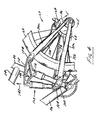
- a portion 105 of chain stays 72a, 72b extends forward of seat tube 22 and is constructed to engage a first end 106 of an absorber, or shock absorber 108.
- a second end 110 of shock absorber 108 is pivotably connected to a rocker arm 112 that is pivotably connected to seat tube 22.
- shock absorber 108 is a gas shock absorber configured to contain a compressed volume of gas.
- Other absorber constructions, such as a spring-based absorber or a fluid-based shock absorber are envisioned and within the scope of the claims.
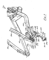
- seat stays 70a, 70b are also rotatable relative to rocker arm 112 about pivot pin 124.
- Chain stays 72a, 72b are also rotatable relative to seat tube 22 about pivot pin 100.
- that portion of suspension system 69 rearward of seat tube 22 rotates generally upward, indicated by arrow 130. This action rotates rocker arm 112 about pivot pin 118 in the direction indicated by arrow 132 thereby subjecting shock absorber 108 to a compressive force, indicated by arrow 134.
- rotor 62 of brake assembly 60 is attached to hub 86 of rear wheel 68.
- Actuation of caliper 64 engages the pads of caliper 64 with rotor 62 thereby imparting a stopping force to wheel 68.
- Caliper 64 is fixedly connected to seat stay 70 such that, during a breaking operation, suspension system 69 is allowed to move in a primarily upward direction rather than a rearward direction.
- suspension system 69 allows suspension system 69 to maintain the attitude of bicycle 10 during a braking operation by limiting the compression of shock absorber 108 by maintaining the weighting of rear wheel 68.
- FIG. 5 shows an exploded view of the assembly of the coaxial connection of seat stays 70a, 70b and chain stays 72a, 72b.
- a first insert 144 includes a stem 146 that is constructed to pass into an opening 148 formed in second end 126 of chain stay 72a.
- Insert 144 includes a contour 150 that is constructed to generally correspond to a contour 152 formed in second end 126 of chain stay 72a proximate opening 148.
- a lip 154 is formed about opening 148 and extends from a side of chain stay 72a generally opposite insert 144. Lip 154 is constructed to generally align opening 148 of chain stay 72a and an opening 156 formed in second end 125 of seat stay 70a.
- Second end 125 of seat stay 70a is constructed to receive a bearing 158 within a cavity 160 formed in second end 125.
- a second insert 170 includes a stem 172 that is constructed to pass through an opening 174 formed in chain stay 72b and an opening 176 formed in seat stay 70b. Insert 170 includes a contour 178 that generally corresponds to a contour 180 of second end 126 of chain stay 72b. Such a mating orientation prevents rotation of second insert 170 relative to chain stay 72b.
- rear wheel assembly 58 When fully assembled, rear wheel assembly 58 is constructed to be received between insert 144 and insert 170. Rear wheel assembly 58 is rotatably supported by an axle whose axis of rotation is coincident with axis 128. It is further appreciated that the axis 128 forms an axis of rotation of rear wheel assembly 58, seat stays 70a, 70b, and chain stays 72a, 72b, through the range of motion of the moveable members of rear suspension system 69.
Landscapes
- Engineering & Computer Science (AREA)
- Mechanical Engineering (AREA)
- Chemical & Material Sciences (AREA)
- Combustion & Propulsion (AREA)
- Transportation (AREA)
- Axle Suspensions And Sidecars For Cycles (AREA)
Abstract
Description
- The present invention relates generally to bicycles and, more particularly, to a rear wheel suspension system and a derailleur assembly of a bicycle.
- The primary structural component of a conventional two-wheel bicycle is the frame. On a conventional road bicycle, the frame is typically constructed from a set of tubular members assembled together to form the frame. For many bicycles, the frame is constructed from members commonly referred to as the top tube, down tube, seat tube, seat stays and chain stays, and those members are joined together at intersections commonly referred to as the head tube, seat post, bottom bracket and rear dropout. The top tube usually extends from the head tube rearward to the seat tube. The head tube, sometimes referred to as the neck, is a short tubular structural member at the upper forward portion of the bicycle which supports the handlebar and front steering fork, which has the front wheel on it. The down tube usually extends downwardly and rearward from the head tube to the bottom bracket, the bottom bracket usually comprising a cylindrical member for supporting the pedals and chain drive mechanism which powers the bicycle. The seat tube usually extends from the bottom bracket upwardly to where it is joined to the rear end of the top tube. The seat tube also usually functions to telescopically receive a seat post for supporting a seat or saddle for the bicycle rider to sit on.
- The chain stays normally extend rearward from the bottom bracket. The seat stays normally extend downwardly and rearward from the top of the seat tube. The chain stays and seat stays are normally joined together with a rear dropout for supporting the rear axle of the rear wheel. The portion of the frame defined by the head tube, seat post and bottom bracket and the structural members that join those three items together can be referred to as the main front triangular portion of the frame, with the seat stays and chain stays defining a rear triangular portion of the frame. The foregoing description represents the construction of a conventional bicycle frame which of course does not possess a suspension having any shock absorbing characteristics.
- The increased popularity in recent years of off-road cycling, particularly on mountains and cross-country, has made a shock absorbing system in many instances a biking necessity. A bicycle with a properly designed suspension system is capable of traveling over extremely bumpy, uneven terrain and up or down very steep inclines. Suspension bicycles are less punishing, reduce fatigue and reduce the likelihood of injury to the rider, and are much more comfortable to ride. For off-road cycling in particular, a suspension system greatly increases the rider's ability to control the bicycle because the wheels remain in contact with the ground as they ride over rocks and bumps in the terrain instead of being bounced into the air as occurs on conventional non-suspension bicycles. Over the last several years the number of bicycles now equipped with suspension systems has dramatically increased. In fact, many bicycles are now fully suspended, meaning that the bicycle has both a front suspension and a rear suspension. Front suspensions were the first to become popular. Designed to remove the pounding to the bicycle front end, the front suspension is simpler to implement than a rear suspension. A front suspension fork is easy to retrofit onto an older model bicycle. On the other hand, a rear suspension will increase traction and assist in cornering and balance the ride.
- During cycling, as the bicycle moves along a desired path, discontinuities of the terrain are communicated to the assembly of the bicycle and ultimately to the rider. Although such discontinuities are generally negligible for cyclists operating on paved surfaces, riders venturing from the beaten path frequently encounter such terrain. With the proliferation of mountain biking, many riders seek the more treacherous trail. Technology has developed to assist such adventurous riders in conquering the road less traveled. Wheel suspension systems are one such feature.
- Riding a fully suspended mountain bike along a rough, rock strewn trail, or even level riding on city and country roads, provides a new degree of safety and comfort to the rider. It is in downhill riding and racing that a rear suspension is most beneficial, but even on ordinary city and country roads, a rear suspension allows the rider to maintain a forward facing orientation to more safely view traffic and road conditions without paying disproportionate attention to stones and potholes immediately below in the rider's path. A number of pivoting "swing arm" suspensions have been developed for rear wheel suspensions on bicycles. In its simplest configuration, the chain stays, which on a conventional bicycle frame are rigidly mounted, are replaced by a pair of swing arms that are pivotably attached at their front ends to the generally fixed front triangular portion of the frame. The pivot is usually located near the bottom bracket where the pedal and crank are supported. The rear ends of the swing arms, which support the rear axle, move upward and downward in response to the rear wheel striking rocks, curbs and other obstructions. The range of movement of the swing arm usually is controlled by a shock absorber affixed between the swing arm and the main front frame. Although such systems have allowed riders to conquer more aggressive terrain, room for improvement still exists.
- Many riders appreciate that braking on mountain bikes can feel "chattery", or as though the wheel is skipping over the terrain rather than rolling thereover. This chatter can detract from rider comfort and confidence as well as adversely affect bicycle performance. During normal operation, as the wheel moves across the ground, a contact patch of the tire is defined as the area of the tire that engages the ground surface. During translation of the suspension system relative to the frame, the contact patch rotates about the tire relative to an axis of rotation of the tire. Typically, the contact patch rotates 10 to 23 degrees for bikes having a suspension which travel ranging from about 122 to approximately 180 millimeters. Other suspension systems provide contact patch rotation in the range of 7 to 12 degrees for bicycles having 120 to 250 millimeters of suspension travel. Rotation of the contact patch contributes to the operational chatter perceived by the rider. Accordingly, it is desired to provide a suspension system having a reduced contact patch rotation.
- Braking forces also affect operation of the suspension system. Braking forces can cause the suspension system to compress or extend based, in part, on the orientation of the brake system with respect to the movable links of the suspension and/or the fixed portion constructed to support the rider. Improper association of the brake system with the rear wheel and the movable members of the suspension system can detrimentally affect bicycle performance as well as stopping ability. During braking, rider momentum generates a forward weight shift which acts to compress the front suspension while extending the rear suspension. The extension of the rear suspension system un-weights the rear wheel and tends to reduce rear tire traction. The reduction in rear tire traction adversely affects braking power in that, if the rear tire traction is sufficiently reduced, the rear tire may be allowed to slide along the ground surface. Such an event can distract a rider and may adversely affect the rider's ability to maintain control of the bicycle. If the loss of rear tire traction during braking, or skid, is unanticipated by the rider, the rider may even crash. Accordingly, it is also desired to provide a suspension system that enhances the attitude of the bicycle during braking so as to provide at least partial compression of the suspension system through a majority of braking conditions.
- Another consideration to bicycle construction is bicycle maintenance. Occasionally, wheels, tires, tubes or other components of a bicycle need replacing or periodic servicing. Although front wheel assemblies are generally equipped with a quick release or the like, rear wheel assemblies are generally require more time and attention to service. For multi-speed bikes, a gear set is commonly associated with the rear wheel and is operatively engaged with a chain of the bicycle. The gear set includes a number of gears of varying diameters that alter the mechanical advantage associated with peddling the bicycle. A derailleur is generally engaged with the chain in close proximity to the gear set and manipulates the chain to facilitate smooth transitioning of the chain between the various gears of the gear set.
- The derailleur is also generally associated with maintaining a desired tension of the chain. The derailleur commonly includes a movable arm that is biased away from the gear set. As the chain is moved along the gear set from a smaller gear to a larger gear, the chain deflects the arm of the derailleur against the bias force to accommodate the chain path associated with the larger gear. As the chain is moved along the gear set from a larger gear to a smaller gear, the bias force maintains the desired tension of the chain to maintain smooth interaction between the gear of the crankset and the gears of the gear set. The gear set, the derailleur, and the chain, and the interaction therebetween complicate any maintenance task that is performed on the rear wheel assembly.
- Commonly, removing the rear wheel either requires or results in removal of the derailleur assembly from the bicycle. The manipulation of multiple independent parts complicates the assembly and construction of the rear wheel assembly. That is, the user must orient or otherwise associate the multiple parts to ensure proper operation of the wheel system when assembled and attached to the bicycle. Doing so can be a time consuming, challenging, and sometimes frustrating endeavor. Accordingly, it is further desired to provide a bicycle wheel assembly with a robust derailleur system that is generally aligned with a rear wheel axis and that is independently engageable with the bicycle assembly.
- The present invention provides a frame assembly, suspension system, and derailleur assembly that overcome one or more of the aforementioned drawbacks. A frame according to a number of the aspects of the invention includes a number of interconnected rotatable members that are configured to absorb shocks and impacts associated with operation of the bicycle. The suspension system includes a chain stay and a seat stay pivotably connected to a frame constructed to support a rider. A rearward axis of rotation of the chain stay and the seat stay are generally concentrically orientated with respect to an axis of rotation of a rear wheel, i.e. a rear wheel axle. Such a construction provides a suspension system that is highly tunable as well as configured to maintain operation of the rear wheel braking system throughout a majority of the travel range of the rear wheel suspension system.
- Another aspect of the invention discloses a bicycle frame assembly having a frame for supporting a rider and a swing arm and seat stay movably connected to the frame. The swing arm has a first end that is pivotably connected to the frame and a second end for pivotably engaging a rear wheel assembly. The seat stay is pivotably connected to the rear wheel assembly such that the seat stay, the swing arm, and a rear wheel have a common axis of rotation. Such a construction functions to reduce the size of the contact patch of the rear wheel during operation.
- A bicycle rear wheel suspension system according to another aspect of the invention is disclosed as having a number of interconnected links. A first link is pivotably connected to a frame member and has a first section that extends rearward of the frame member for supporting a wheel and a second section that extends forward of the frame member. A rocker arm is pivotably connected to the frame and has a first portion that extends rearward of the frame member and a second portion that extends forward of the frame member. A second link is pivotably disposed between the first section of the first link and the first portion of the rocker arm such that the first link can the second link can rotate about a common axis. The system includes an arrestor that has a first end connected to the second section of the first link and a second end connected to the second portion of the rocker arm. Accordingly, the arrestor is free-floating or not otherwise rigidly connected to the frame.
- A further aspect of the invention discloses a bicycle frame having a first portion for supporting a rider and a number of interconnected pivotable members. An arm is pivotably attached to the first portion of the frame. A first member is pivotably attached to the first portion and has a first end and a second end. The first end of the first member is connected to the arm by an absorber. A second member also includes a first end and a second end. The first end is connected to an end of the arm generally opposite the absorber and the second end is pivotably connected to the second end of the first member such that the first and second members are rotatable about a common axis.
- A derailleur according to a further aspect of the invention is constructed to be pivotably connected to the suspension system such that the derailleur pivots about an axis that is aligned with the axis of rotation of the rear wheel. The derailleur is independently secured to the suspension system such that the rear wheel can be removed from the bicycle without interfering with the attachment of the derailleur to the bicycle.
- Another aspect of the invention discloses a bicycle assembly having a number of movable suspension members and a derailleur assembly that is secured to the bicycle assembly aligned with an axis of rotation of the movable members. The bicycle derailleur assembly includes a body and a pair of guide members for steering a bicycle chain. The pair of guide members is secured to the body such that each of the pair of guide members can rotate relative to the body. The assembly includes a pivot having a first end for engaging the body and a second end for engaging a bicycle frame. The pivot is connected to the body and the bicycle frame such that the body is rotatable about an axis generally aligned with a wheel axis and such that a wheel associated with the axis is removable from the bicycle frame independent of the body. Such an assembly allows the rear wheel to be removed from the bicycle without otherwise interfering with the derailleur assembly.
- Yet another aspect of the invention discloses a bicycle assembly having a main frame portion and a first link and a second link extending rearward of the main frame portion. The second link includes a first end that extends away from a point of the main frame portion that is offset from the first link and a second end. The second end extends rearward from the main frame portion toward the first link. An axle provides an axis of rotation and is engaged with the first link and the second link. A wheel is attached to a gear set that is engaged with a chain. The wheel is attached to the gear set such that rotation of the gear set rotates the wheel about the axis of rotation. A derailleur is engaged with the chain and is attached to the bicycle assembly about the axis of rotation and axially offset from the axle. Such a bicycle assembly provides a derailleur system that is robust and can withstand the rigors associated with extended operation.
- An even further aspect of the invention discloses a bicycle assembly having a frame with a first portion for supporting a rider. A first and a second arm extend rearward of the first portion. The assembly includes a pivotable connection between the first arm and the second arm. An axle is engaged with the first arm and the second arm and has an axis that is aligned with the pivotable connection between the first arm and the second arm. A derailleur that is pivotable about the axis of the axle is secured to one of the first arm and the second arm independent of the axle such that the axle can be removed without affecting connection of the derailleur to the bicycle. Such a construction provides a robust derailleur system without unnecessarily complicating bicycle maintenance.
- These and various other aspects, features, and advantages of the present invention will be made apparent from the following detailed description and the drawings.
- The drawings illustrate one preferred embodiment presently contemplated for carrying out the invention.
- In the drawings:
-
Fig. 1 is an elevational view of a bicycle equipped with a frame, a suspension system, and a derailleur system according to the present invention. -
Fig. 2 is a perspective view of the frame assembly shown inFig. 1 . -
Fig. 3 is an elevational view of a portion of the bicycle shown inFig. 1 with the suspension system in a compressed position. -
Fig. 4 is a view similar that shown inFig. 3 with the suspension system in an extended position. -
Fig. 5 is an exploded view of a portion of the suspension system generally along line 5-5shown inFig. 4 . -
Fig. 6 is a geometric representation of the movement of the suspension of the frame assembly shown inFig. 2 . -
Fig. 7 is a detailed elevational view of the derailleur assembly shown inFig. 1 . -
Fig. 8 is a perspective view of the derailleur assembly shown inFig. 7 . -
Fig. 9 is a view similar toFig. 8 with the derailleur assembly exploded from the bicycle frame assembly. -
Fig. 1 shows abicycle 10 having aframe assembly 12 equipped with a rear wheel suspension system according to the present invention.Bicycle 10 includes a seat 16 andhandlebars 18 that are attached to frameassembly 12. Aseat post 20 is connected to seat 16 and slidably engages aseat tube 22 offrame assembly 12. Atop tube 24 and adown tube 26 extend forwardly fromseat tube 22 to ahead tube 28 offrame assembly 12.Handlebars 18 are connected to a stem 30 that passes throughhead tube 28 and engages a fork crown 32. A pair offorks 34 extend from generally opposite ends of fork crown 32 and are constructed to support a front wheel assembly 36 at an end of each fork or afork tip 38.Fork tips 38 engage generally opposite sides of anaxle 40 that is constructed to engage ahub 42 of front wheel assembly 36. A number ofspokes 44 extend fromhub 42 to arim 46 of front wheel assembly 36. Atire 48 is engaged withrim 46 such that rotation oftire 48, relative toforks 34, rotatesrim 46 andhub 42. -
Bicycle 10 includes afront brake assembly 50 having an actuator 52 attached tohandlebars 18 and a pair ofbrake pads 54 positioned on generally opposite sides of front wheel assembly 36.Brake pads 54 are constructed to engage abrake wall 56 ofrim 46 thereby providing a stopping or slowing force to front wheel assembly 36. Arear wheel assembly 58 includes adisc brake assembly 60 having arotor 62 and acaliper 64 that are positioned proximate arear axle 66. Arear wheel 68 is positioned generally concentrically aboutrear axle 66. Understandably, front wheel assembly 36 andrear wheel assembly 58 could be equipped with a brake assembly generally similar tofront brake assembly 50 ordisc brake assembly 60. - A rear
wheel suspension system 69 is pivotably connected to frame 12 to allowrear wheel 68 to move independent of seat 16 andhandlebars 18.Suspension system 69 includes aseat stay 70 and achain stay 72 that offsetrear axle 66 from acrankset 74.Crankset 74 includes a pedal 76 that is operationally connected to achain 78 via a chain ring orsprocket 80. Rotation ofchain 78 communicates a drive force to a rear section 82 ofbicycle 10. Agear cluster 84 is positioned at rear section 82 and engaged bychain 78.Gear cluster 84 is generally concentrically orientated with respect torear axle 66 and includes a number of variable diameter gears.Gear cluster 84 is operationally connected to ahub 86 of a rear wheel 88 ofrear wheel assembly 58. A number of spokes 90 extend radially betweenhub 86 and a rim 92 of rear wheel 88. As is commonly understood, rider operation of pedals 76drives chain 78 thereby driving rear wheel 88 which in turn propelsbicycle 10. As described further with respect toFigs. 7-9 , aderailleur assembly 93 is secured tobicycle 10 and engageschain 78 to laterally translatechain 78 relative to gearcluster 84. The lateral translation ofchain 78 to engagechain 78 with different gears ofgear cluster 84 is commonly referred to as shifting. - As shown in
Fig. 2 ,frame assembly 12 includes afirst portion 94 that generally includesseat tube 22,top tube 24,down tube 26, andhead tube 28. Abottom bracket 96 is formed proximate the interface ofseat tube 22 and downtube 26 and is constructed to operatively connectcrankset 74 tobicycle frame assembly 12. Afirst end 98 of chain stay 72 is pivotably connected toseat tube 22proximate bottom bracket 96. Apivot pin 100 passes throughseat tube 22 generally between a forward edge 102 and arearward edge 104 ofseat tube 22.Pivot pin 100 pivotably connects alternate side chain stays 72a, 72b toseat tube 22. A portion 105 of chain stays 72a, 72b extends forward ofseat tube 22 and is constructed to engage afirst end 106 of an absorber, orshock absorber 108. Asecond end 110 ofshock absorber 108 is pivotably connected to arocker arm 112 that is pivotably connected toseat tube 22. Preferably,shock absorber 108 is a gas shock absorber configured to contain a compressed volume of gas. Other absorber constructions, such as a spring-based absorber or a fluid-based shock absorber are envisioned and within the scope of the claims. -
Rocker arm 112 includes a first portion 114 that extends forward ofseat tube 22 and a second portion 116 that extends rearwardly fromseat tube 22. Apivot pin 118 securesrocker arm 112 toseat tube 22 and a web wall 120 extends between generally opposite sides 112a, 112b ofrocker arm 112 such that opposite sides 112a, 112b ofrocker arm 112 generally flankseat tube 22. Second portion 116 ofrocker arm 112 extends rearward fromseat tube 22 and is pivotably connected to afirst end 121 ofseat stay 70.Seat stay 70 includes generallyopposite sides first end 121 by abracket 122. Apivot pin 124 pivotably connects second portion 116 ofrocker arm 112 tofirst end 121 of seat stays 70a, 70b. - A
second end 125 of seat stays 70a, 70b is pivotably connected to asecond end 126 of chain stays 72a, 72b. An axis of rotation between seat stays 70a, 70b and chain stays 72a, 72b, indicated byline 128, is generally concentrically oriented torear axle 66. That is,rear axle 66, seat stays 70a, 70b, and chain stays 72a, 72b are connected to be rotatable about a common axis, i.e. axis 128. - As shown in
Figs. 3 and4 , in addition to the relative rotation between seat stays 70a, 70b and chain stays 72a, 72b, seat stays 70a, 70b are also rotatable relative torocker arm 112 aboutpivot pin 124. Chain stays 72a, 72b are also rotatable relative toseat tube 22 aboutpivot pin 100. As shown inFig. 3 , when subjected to an impact, that portion ofsuspension system 69 rearward ofseat tube 22 rotates generally upward, indicated by arrow 130. This action rotatesrocker arm 112 aboutpivot pin 118 in the direction indicated byarrow 132 thereby subjectingshock absorber 108 to a compressive force, indicated by arrow 134. During this same movement ofrocker arm 112, chain stays 72a, 72b rotate in the direction indicated by arrow 136 aboutpivot pin 100. This action displaces forward portion 105 of chain stays 72a, 72b in the same direction as force 134 thereby allowing a portion of force 134 to be absorbed by the mechanical association of seat stays 70a, 70b and chain stays 72a, 72b. - As shown in
Fig. 4 , whenrear wheel 68 overcomes an obstacle or other impact,suspension system 69 returns to a generally unloaded orientation such that there is a collective rotation ofrocker arm 112, seat stays 70, and chain stays 72 in the direction, indicated by arrow 140. Rotation 140 is associated with the restoring force, indicated by arrow 142, generated byshock absorber 108. - Still referring to
Figs. 3 and4 ,rotor 62 ofbrake assembly 60 is attached tohub 86 ofrear wheel 68. Actuation ofcaliper 64 engages the pads ofcaliper 64 withrotor 62 thereby imparting a stopping force towheel 68.Caliper 64 is fixedly connected to seat stay 70 such that, during a breaking operation,suspension system 69 is allowed to move in a primarily upward direction rather than a rearward direction. Such a configuration allowssuspension system 69 to maintain the attitude ofbicycle 10 during a braking operation by limiting the compression ofshock absorber 108 by maintaining the weighting ofrear wheel 68. -
Fig. 5 shows an exploded view of the assembly of the coaxial connection of seat stays 70a, 70b and chain stays 72a, 72b. Afirst insert 144 includes a stem 146 that is constructed to pass into anopening 148 formed insecond end 126 ofchain stay 72a.Insert 144 includes acontour 150 that is constructed to generally correspond to acontour 152 formed insecond end 126 ofchain stay 72aproximate opening 148. Alip 154 is formed about opening 148 and extends from a side of chain stay 72a generally oppositeinsert 144.Lip 154 is constructed to generally align opening 148 ofchain stay 72a and anopening 156 formed insecond end 125 ofseat stay 70a. Such a construction ensures the generally concentric and coaxial alignment ofchain stay 72a and seat stay 70a with axis ofrotation 128.Second end 125 ofseat stay 70a is constructed to receive a bearing 158 within acavity 160 formed insecond end 125. - An
end cap 162 engagesaxle 66 so as to secure bearing 158 incavity 160. Bearing 158 and opening 148 ofchain stay 72a are constructed to engage stem 146 ofinsert 144 such that chain stay 72a andseat stay 70a a rotate independently aboutaxis 128. Such a construction allows for independent and coaxial rotation ofseat stay 70a and chain stay 72a relative toaxis 128. Similarly, asecond insert 170 includes astem 172 that is constructed to pass through anopening 174 formed in chain stay 72b and anopening 176 formed inseat stay 70b.Insert 170 includes a contour 178 that generally corresponds to acontour 180 ofsecond end 126 of chain stay 72b. Such a mating orientation prevents rotation ofsecond insert 170 relative to chain stay 72b. Abearing 182 engages acavity 184 formed insecond end 125 ofseat stay 70b and engages stem 172 ofinsert 170. Anend cap 186 and a spacer 188 are positionedproximate bearing 182 and configured to engagestem 172 ofinsert 170. Spacer 188 is constructed to generally enclose bearing 182 withincavity 184 and prevents dirt or other debris from foulingbearing 182. - When fully assembled,
rear wheel assembly 58 is constructed to be received betweeninsert 144 and insert 170.Rear wheel assembly 58 is rotatably supported by an axle whose axis of rotation is coincident withaxis 128. It is further appreciated that theaxis 128 forms an axis of rotation ofrear wheel assembly 58, seat stays 70a, 70b, and chain stays 72a, 72b, through the range of motion of the moveable members ofrear suspension system 69. -
Fig. 6 shows a geometrical representation of the operation ofsuspension system 69. As shown inFig. 5 , asbicycle 10 traverses terrain, indicated by line 190 a shock absorber 192 offront fork 34 absorbs impacts experienced by front wheel assembly 36 thereby allowing thefront tire 48 to deflect over the obstruction. A large portion of the shock or impact experienced byrear wheel 68 is absorbed by the collective operation and movement of seat stays 70, chain stays 72,rocker arm 112, andshock absorber 108.Wheel 68 has a normaloperation contact patch 194 that is generally centrally positioned beneath the axis of rotation ofaxle 66. During braking, the concentric orientation of the pivot axis of seat stays 70 relative to chain stays 72 provides for both the substantially vertical translation ofaxle 66 and a substantially reduced range of translation ofcontact patch 194 through the movable range ofsuspension system 69. Preferably,contact patch 194 translates from about 0 to about 7 degrees for a suspension system having about 75 mm to about 250 mm of translation. Understandably, other ranges of contact patch rotation and suspension system travel are envisioned. Accordingly,suspension system 69 provides enhanced operation of the braking system throughout the travel range of the suspension system thereby providing a bicycle that is responsive to the dynamic riding conditions as well as enjoyable to ride. - Referring to
Fig. 7 ,derailleur assembly 93 includes abody 200 having afirst portion 202 that is pivotably connected to asecond portion 204.Derailleur assembly 93 includes afirst guide member 206 and asecond guide member 208 that each engagechain 78. A number of teeth 210 extend from each ofguide members chain 78. Afirst pivot 212 securesfirst guide member 206 tofirst portion 202 ofbody 200 such thatguide member 206 can rotate relative thereto. Asecond pivot 214 securessecond guide member 208 tobody 200.Chain 78 passes aboutgear cluster 84 and first andsecond guide members Chain 78 operationally engageschain ring sprocket 80 such that rotation of pedals 76 rotateschain 78 about the gears ofgear cluster 84, and throughderailleur assembly 93 aboutguide members -
Gear cluster 84 includes a number of variable diameter gears 218, 220, 222 configured to alter the mechanical advantage associated with the operation of pedals 76. It is appreciated that although threegears chain ring sprocket 80 is shown as a single gear, other configurations are envisioned such as two or more gears associated with either ofgear cluster 84 orchain ring sprocket 80. Lateral translation ofguide member 206 or guidemember 208 relative torear axle 66 andgear cluster 84 provides a lateral force tochain 78 thereby translatingchain 78 between themultiple gears gear cluster 84.Derailleur assembly 93 is pivotably secured about the axis associated withrear axle 66 and is positioned outboard ofseat stay 70b and chain stay 72b.Derailleur assembly 93 is connected tobicycle 10 to be pivotable aboutrear axle 66 such thatderailleur 93 maintains a generally uniform tension ofchain 78 whenchain 78 is engaged with any of thegears gear cluster 84. - Referring to
Fig. 8 ,derailleur assembly 93 is secured tobicycle 10 independent ofrear axle 66. As shown inFig. 8 ,rear wheel assembly 58, includingrear wheel 68,gear cluster 84, andrear axle 66, has been removed frombicycle 10 whilederailleur assembly 93 remains attached thereto.Derailleur assembly 93 is attached tobicycle 10 so as to be rotatable aboutaxis 128, or the axis of rotation ofrear wheel assembly 58.Derailleur assembly 93 is rotatable aboutaxis 128 and independently securable tobicycle 10 relative toaxle 66 by being offset in the axial direction alongaxis 128 associated withaxle 66. - Referring to
Fig. 9 , apivot 226 includes a first end 228 that extends outwardly from an outboard face 230 ofseat stay 70b. A second end 232 ofpivot 226 is received within a cavity 234 formed inseat stay 70b. Such a construction ensures axial alignment ofpivot 226,rear wheel axle 66, andaxis 128. An outer surface 238 of first end 228 ofpivot 226 slidably engages abore 240 formed through a first end 242 ofbody 200 ofderailleur assembly 93. Arib 244 is formed on aninboard facing side 246 ofbody 200 proximate first end 242. Agroove 247 is formed aboutpivot 226 and is constructed to cooperate withrib 244 to enhance the co-axial engagement betweenpivot 226 and bore 240. Acap 248 engagespivot 226 and securesbody 200 ofderailleur assembly 93 tobicycle 10.Cap 248 includes a land 250 that cooperates with anoutboard face 252 of end 242 ofbody 200.Cap 248 could include interior or exterior threading configured to cooperate with a threading ofpivot 226. Alternatively,cap 248 and pivot 226 could be configured to cooperate with and receive a fastener for securingcap 248 to pivot 226. Regardless of the mode and/or means of connection,cap 248 and pivot 226 cooperate to pivotablysecure body 200 ofderailleur assembly 93 tobicycle 10. -
Rib 244 andgroove 247, the axial length of outer surface 238 of first end 228 ofpivot 226, and the engagement of land 250 ofcap 248 withoutboard face 252 ofbody 200 each function to ensure thatbody 200 is secured tobicycle 10 for rotation aboutaxis 128. Furthermore, aligning the axis of rotation ofderailleur assembly 93 relative tobicycle 10 with the axis of rotation ofrear wheel assembly 66, and therefore gearcluster 84, reduces the offset between the engagement ofchain 78 andguide members body 200 and localizes the forces associated with the operation ofderailleur assembly 93 along an axis associated with the origin of the forces, i.e. the engagement ofchain 78 with arespective gear gear cluster 84. Such a construction provides arobust derailleur assembly 93 that is lightweight and highly compact. - A bicycle frame assembly according to a combination of aspects of the invention includes a number of rotatable members configured to absorb shocks and impacts associated with operation of the bicycle. The assembly includes a frame constructed to support a rider and a chain stay having a rearward end that extends toward a wheel hub and a forward end that is pivotably connected to the frame. An absorber is pivotably connected to the forward end of the chain stay and extends to a rocker arm that is pivotably connected to the frame. A seat stay is pivotably connected to a rearward end of the rocker arm and extends to the rearward end of the chain stay. The rearward ends of the seat stay and the chain stay are pivotably connected to rotate about a common axis. Such a construction provides a bicycle suspension system that has an absorbing member that is not rigidly connected to a fixed frame member as well as a suspension system with enhanced operation throughout a range of operating positions of the members of the suspension system. The suspension system maintains a reduced contact patch of the rear wheel over the range of motion of the suspension system thereby enhancing operation of the bicycle.
- Even with the suspension features discussed above,
derailleur assembly 93 allows a rider to quickly and conveniently removerear wheel assembly 58 frombicycle 10 without affecting the engage ofderailleur assembly 93 withbicycle 10. Such an assembly simplifies routine bicycle maintenance and/or service by allowing a rider to remove only those systems which require servicing. The concentric association of the engagement ofderailleur assembly 93 withbicycle 10 and axis ofrotation 128 ofrear wheel assembly 58 provides a derailleur assembly that is lightweight and robust. - A bicycle constructed in accordance with one or more aspects of the present invention provides an impact absorbing suspension with beneficial braking performance, provides a suspension system wherein a seat stay and a chain stay are pivotable about an axis aligned with an axis of rotation of the rear wheel, and is equipped with a derailleur assembly that is robust and reduces the time and/or effort associated with removing and/or replacing the bicycle rear wheel assembly by maintaining it's engagement with the bicycle in an orientation concentric to the rear wheel axle independent of the real wheel axle's engagement with the bicycle.
- The present invention has been described in terms of the preferred embodiment, and it is recognized that equivalents, alternatives, and modifications, aside from those expressly stated, are possible and within the scope of the appending claims.
Claims (45)
- A bicycle frame assembly comprising:a frame for supporting a rider;a swing arm having a first end pivotably connected to the frame and a second end for pivotably engaging a rear wheel assembly; anda seat stay pivotably connected to the rear wheel assembly such that the seat stay, the swing arm, and a rear wheel have a common axis of rotation.
- The bicycle frame assembly of claim 1 further comprising a rocker arm attached to the frame and connected to an end of the seat stay generally opposite the common axis of rotation.
- The bicycle frame assembly of claim 2 further comprising a shock absorber attached to the rocker arm generally forward of a seat tube of the frame.
- The bicycle frame assembly of claim 3 wherein an end of the shock absorber generally opposite the rocker arm is pivotably attached to the swing arm.
- The bicycle frame assembly of claim 4 wherein the swing arm and the shock absorber are pivotably connected at a location generally forward of the seat tube.
- The bicycle frame assembly of any one of the preceding claims wherein the rear wheel has a contact patch between about 0 and about 7 degrees for a bicycle having a swing arm travel between about 75 mm to about 250 mm.
- The bicycle frame assembly of any one of the preceding claims further comprising another swing arm and another seat stay attached to the frame assembly such that the swing arms and the seat stays generally flank the rear wheel.
- A bicycle rear wheel suspension system comprising:a first link pivotably connected to a frame member and having a first section for supporting a wheel extending rearward of the frame member and a second section extending forward of the frame member;a rocker arm pivotably connected to the frame and having a first portion extending rearward of the frame member and a second portion extending forward of the frame member;a second link pivotably disposed between the first section of the first link and the first portion of the rocker arm such that the first link and the second link are pivotable about a common axis; andan arrestor having a first end connected to the second section of the first link and a second end connected to the second portion of the rocker arm.
- The suspension system of claim 8 further comprising an axle having the wheel mounted thereto, the axle constructed to support the wheel for rotation about the common axis.
- The suspension system of claim 8 or claim 9 wherein the arrestor is a shock absorber having one of a spring, a gas charge, or a fluid.
- The suspension system of any of claims 8, 9, or 10 wherein the frame member is a seat tube.
- The suspension system of any of claims 8-11 wherein the wheel has a contact patch between about 0 degrees and about 7 degrees.
- The suspension system of any of claims 8-12 wherein the first portion of the rocker arm is longer than the second portion of the rocker arm.
- The suspension system of any of claims 8-13 wherein the first link includes a pair of arms constructed to flank the wheel and a bracket that extends between the pair of arms proximate the frame member.
- The suspension system of any of claims 8-14 wherein the rocker arm includes a generally U-shaped recess constructed to receive the frame member.
- A bicycle frame comprising:a first portion for supporting a rider;an arm pivotably attached to the first portion;a first member pivotably attached to the first portion and having a first end connected to the arm by an absorber and a second end; anda second member having a first end connected to an end of the arm generally opposite the absorber and a second end pivotably connected to the second end of the first member such that the first and second members are rotatable about a common axis.
- The bicycle frame of claim 16 further comprising a rear wheel axle located at the common axis and constructed to support a wheel.
- The bicycle frame of claim 16 or claim 17 further comprising another first member and another second member positioned on a side of the first portion generally opposite the first member and the second member to flank a wheel.
- The bicycle frame of claim 18 wherein the first member and the another first member have different shapes.
- The bicycle frame of any of claims 16-19 wherein the arm is pivotably attached to a seat tube and is rotatable about an axis positioned between a forward edge and a rearward edge of the seat tube.
- A bicycle frame system comprising:a frame constructed to support a rider; anda rear wheel suspension assembly constructed to support a rear wheel such that an axis of rotation of the rear wheel forms a pivot with a swing arm and a seat stay and is movable relative to the frame to generally maintain a generally uniform braking performance across a substantial portion of a range of motion of the rear wheel axis.
- The bicycle frame system of claim 21 wherein the swing arm is pivotably connected to the frame at an end remote from the pivot.
- The bicycle frame system of claim 21 or claim 22 wherein translation of the axis of rotation is generally unaffected by a braking operation.
- The bicycle frame system of any of claims 21-23 wherein the rear suspension system limits radial translation of a contact patch across the substantial portion of the range of motion of the rear wheel axis.
- The bicycle frame system of any of claims 21-24 further comprising a rocker arm pivotably connected to the frame, the seat stay and a shock absorber being pivotably connected to generally opposite sides of the rocker arm.
- A bicycle derailleur assembly comprising:a body having a pair of guide members for steering a bicycle chain secured to the body such that each of the pair of guide members can rotate relative to the body; anda pivot having a first end for engaging the body and a second end for engaging a bicycle frame, the pivot connected to the body and the bicycle frame such that the body is rotatable about an axis generally aligned with a wheel axis and such that a wheel associated with the axis is removable from the bicycle frame independent of the body.
- The derailleur system of claim 26 wherein the bicycle frame further comprises a swing arm and a seat stay that are connected to the bicycle frame and rotatable about the axis of rotation of the body.
- The derailleur system of claim 27 wherein the swing arm and the seat stay rotate relative to one another about the axis of rotation of the body.
- The derailleur system of any of claims 26-28 further comprising a passage formed through the body, the passage having a first side constructed to engage the pivot and a second side for engaging a nut constructed to engage the pivot.
- The derailleur system of any of claims 26-29 wherein the body comprises a first side wall and a second sidewall positioned on generally opposite sides of the pair of guide members.
- The derailleur system of claim 30 further comprising a pair of pivots, each pivot extending between each of the first sidewall and the second sidewall and passing through a respective guide member.
- The derailleur system of any of claims 26-31 wherein each guide member further comprises a number of teeth formed about a perimeter of the guide member and constructed to cooperate with the bicycle chain, at least one guide member constructed to move laterally relative to a gear set.
- A bicycle assembly comprising:a main frame portion;a first link extending rearward from the main frame portion;a second link having a first end extending away from a point of the main frame portion that is offset for the first link and a second end extending rearward from the main frame portion toward the first link;an axle providing an axis of rotation and engaged with the first link and the second link;a gear set engaged with a chain;a wheel attached to the gear set such that rotation of the gear set rotates the wheel about the axis of rotation; anda derailleur engaged with the chain and attached to the bicycle assembly about the axis of rotation and axially offset from the axle.
- The bicycle assembly of claim 33 further comprising a rocker arm pivotably connected to the first end of the second link, pivotably connected the main frame portion, and pivotably connected to an arrestor.
- The bicycle assembly of claim 34 wherein the arrestor is positioned forward of a seat tube of the main frame portion and the second link engages the rocker arm rearward of the main frame portion.
- The bicycle assembly of any of claims 33-35 wherein the first link, the second link, and the derailleur are pivotable about a common axis.
- The bicycle assembly of any of claims 33-36 further comprising a pivot aligned with the axle and extending in a direction away from the gear set for engaging the derailleur.
- The bicycle assembly of claim 37 further comprising a lug engaged with the pivot and the derailleur such that the pivot and lug engage from generally opposite sides of the derailleur.
- The bicycle assembly of any of claims 33-38 further comprising another first link and another second link attached to the bicycle assembly such that the first links and the second links generally flank the wheel.
- The bicycle assembly of any of claims 33-39 wherein the derailleur further comprises a pair of gears constructed to interact with the chain such that lateral translation of a portion of the derailleur biases the chain laterally relative to gear set.
- A bicycle assembly comprising:a frame having a first portion for supporting a rider;a first arm extending rearward of the first portion;a second arm extending rearward of the first portion;a pivotable connection between the first arm and the second arm;an axle engaged with the first arm and the second arm and having an axis that is aligned with the pivotable connection between the first arm and the second arm; anda derailleur pivotable about the axis and secured to one of the first arm and the second arm independent of the axle such that the axle can be removed without affecting connection of the derailleur.
- The bicycle assembly of claim 41 further comprising a wheel engaged with the axle and rotatable about the axis.
- The bicycle assembly of claim 41 or claim 42 further comprising another first arm and another second arm that are pivotably connected to pivot above the axis of the axle.
- The bicycle frame of any of claims 41-43 further comprising a stem engaged with one of the first arm and the second arm, the stem being aligned with the axle and engaged with a bore formed in the derailleur.
- The bicycle frame of claim 44 further comprising a cap constructed to engage the stem for securing the derailleur about the pivot.
Priority Applications (3)
| Application Number | Priority Date | Filing Date | Title |
|---|---|---|---|
| EP12179271.7A EP2527239B1 (en) | 2007-04-16 | 2007-09-05 | Bicycle rear wheel suspension |
| EP11174031A EP2377751B1 (en) | 2007-04-16 | 2007-09-05 | Bicycle suspension |
| EP20110174035 EP2377752B1 (en) | 2007-04-16 | 2007-09-05 | Bicycle suspension |
Applications Claiming Priority (2)
| Application Number | Priority Date | Filing Date | Title |
|---|---|---|---|
| US11/735,816 US7837213B2 (en) | 2007-04-16 | 2007-04-16 | Bicycle rear wheel suspension system |
| US11/839,931 US7703785B2 (en) | 2007-08-16 | 2007-08-16 | Bicycle derailleur system |
Related Child Applications (4)
| Application Number | Title | Priority Date | Filing Date |
|---|---|---|---|
| EP12179271.7A Division EP2527239B1 (en) | 2007-04-16 | 2007-09-05 | Bicycle rear wheel suspension |
| EP20110174035 Division EP2377752B1 (en) | 2007-04-16 | 2007-09-05 | Bicycle suspension |
| EP11174031.2 Division-Into | 2011-07-14 | ||
| EP11174035.3 Division-Into | 2011-07-14 |
Publications (3)
| Publication Number | Publication Date |
|---|---|
| EP1982911A2 true EP1982911A2 (en) | 2008-10-22 |
| EP1982911A3 EP1982911A3 (en) | 2009-12-09 |
| EP1982911B1 EP1982911B1 (en) | 2011-11-09 |
Family
ID=38606623
Family Applications (4)
| Application Number | Title | Priority Date | Filing Date |
|---|---|---|---|
| EP07253508A Active EP1982911B1 (en) | 2007-04-16 | 2007-09-05 | Bicycle rear wheel suspension |
| EP20110174035 Active EP2377752B1 (en) | 2007-04-16 | 2007-09-05 | Bicycle suspension |
| EP12179271.7A Active EP2527239B1 (en) | 2007-04-16 | 2007-09-05 | Bicycle rear wheel suspension |
| EP11174031A Active EP2377751B1 (en) | 2007-04-16 | 2007-09-05 | Bicycle suspension |
Family Applications After (3)
| Application Number | Title | Priority Date | Filing Date |
|---|---|---|---|
| EP20110174035 Active EP2377752B1 (en) | 2007-04-16 | 2007-09-05 | Bicycle suspension |
| EP12179271.7A Active EP2527239B1 (en) | 2007-04-16 | 2007-09-05 | Bicycle rear wheel suspension |
| EP11174031A Active EP2377751B1 (en) | 2007-04-16 | 2007-09-05 | Bicycle suspension |
Country Status (3)
| Country | Link |
|---|---|
| EP (4) | EP1982911B1 (en) |
| AT (1) | ATE532696T1 (en) |
| ES (4) | ES2586706T3 (en) |
Cited By (4)
| Publication number | Priority date | Publication date | Assignee | Title |
|---|---|---|---|---|
| ES2369287A1 (en) * | 2011-08-11 | 2011-11-29 | Orbea S. Coop. | Bicycle frame set for building a bicycle frame, with a rear dropout that allows the mounting of different types of wheel axles |
| US8235409B2 (en) | 2007-04-16 | 2012-08-07 | Trek Bicycle Corporation | Bicycle rear wheel suspension system |
| DE102013004896A1 (en) * | 2013-03-21 | 2014-09-25 | Ghost-Bikes GmbH | Rear suspension system for a bicycle and bicycle frame |
| GB2525870A (en) * | 2014-05-06 | 2015-11-11 | Chain Reaction Cycles Ltd | Rear suspension system for velocipedes |
Families Citing this family (3)
| Publication number | Priority date | Publication date | Assignee | Title |
|---|---|---|---|---|
| EP3556647B1 (en) * | 2018-04-20 | 2021-11-17 | YT Industries GmbH | Device for attaching a switchgear to a bicycle frame |
| DE102018206134B4 (en) * | 2018-04-20 | 2024-04-25 | YT Industries GmbH | Device for attaching a rear derailleur to a bicycle frame |
| DE102018222834A1 (en) | 2018-12-21 | 2020-06-25 | Sram Deutschland Gmbh | Bracket and bike with a bracket |
Citations (3)
| Publication number | Priority date | Publication date | Assignee | Title |
|---|---|---|---|---|
| WO1999044880A1 (en) | 1998-03-02 | 1999-09-10 | Ellsworth Anthony S | Bicycle suspension apparatus and related method |
| DE202006012023U1 (en) | 2005-08-11 | 2006-10-19 | Simplon Fahrrad Gmbh | Connecting device for damping unit, has lower connecting lever mounted above rotary hole to attach driving crank at bicycle frame and connected with end of damping unit, so that rotatable connecting point acts as sliding position point |
| WO2008027277A2 (en) | 2006-08-25 | 2008-03-06 | David Weagle | Vehicle suspension systems for seperated acceleration responses |
-
2007
- 2007-09-05 ES ES12179271.7T patent/ES2586706T3/en active Active
- 2007-09-05 EP EP07253508A patent/EP1982911B1/en active Active
- 2007-09-05 ES ES07253508T patent/ES2374312T3/en active Active
- 2007-09-05 EP EP20110174035 patent/EP2377752B1/en active Active
- 2007-09-05 AT AT07253508T patent/ATE532696T1/en active
- 2007-09-05 EP EP12179271.7A patent/EP2527239B1/en active Active
- 2007-09-05 ES ES11174035.3T patent/ES2543906T3/en active Active
- 2007-09-05 ES ES11174031T patent/ES2400802T3/en active Active
- 2007-09-05 EP EP11174031A patent/EP2377751B1/en active Active
Patent Citations (3)
| Publication number | Priority date | Publication date | Assignee | Title |
|---|---|---|---|---|
| WO1999044880A1 (en) | 1998-03-02 | 1999-09-10 | Ellsworth Anthony S | Bicycle suspension apparatus and related method |
| DE202006012023U1 (en) | 2005-08-11 | 2006-10-19 | Simplon Fahrrad Gmbh | Connecting device for damping unit, has lower connecting lever mounted above rotary hole to attach driving crank at bicycle frame and connected with end of damping unit, so that rotatable connecting point acts as sliding position point |
| WO2008027277A2 (en) | 2006-08-25 | 2008-03-06 | David Weagle | Vehicle suspension systems for seperated acceleration responses |
Cited By (7)
| Publication number | Priority date | Publication date | Assignee | Title |
|---|---|---|---|---|
| US8235409B2 (en) | 2007-04-16 | 2012-08-07 | Trek Bicycle Corporation | Bicycle rear wheel suspension system |
| US8882127B2 (en) | 2007-04-16 | 2014-11-11 | Trek Bicycle Corporation | Bicycle rear wheel suspension system |
| ES2369287A1 (en) * | 2011-08-11 | 2011-11-29 | Orbea S. Coop. | Bicycle frame set for building a bicycle frame, with a rear dropout that allows the mounting of different types of wheel axles |
| DE102013004896A1 (en) * | 2013-03-21 | 2014-09-25 | Ghost-Bikes GmbH | Rear suspension system for a bicycle and bicycle frame |
| DE102013004896B4 (en) * | 2013-03-21 | 2016-12-08 | Ghost-Bikes GmbH | Rear suspension system for a bicycle and bicycle frame |
| GB2525870A (en) * | 2014-05-06 | 2015-11-11 | Chain Reaction Cycles Ltd | Rear suspension system for velocipedes |
| GB2525870B (en) * | 2014-05-06 | 2017-01-04 | Chain Reaction Cycles Ltd | Rear suspension system for velocipedes |
Also Published As
| Publication number | Publication date |
|---|---|
| EP2527239B1 (en) | 2016-05-11 |
| ES2374312T3 (en) | 2012-02-15 |
| EP2377752A1 (en) | 2011-10-19 |
| EP2527239A1 (en) | 2012-11-28 |
| EP2377752B1 (en) | 2015-04-29 |
| EP2377751A1 (en) | 2011-10-19 |
| ES2586706T3 (en) | 2016-10-18 |
| ES2400802T3 (en) | 2013-04-12 |
| ATE532696T1 (en) | 2011-11-15 |
| EP2377751B1 (en) | 2013-01-09 |
| ES2543906T3 (en) | 2015-08-25 |
| EP1982911B1 (en) | 2011-11-09 |
| EP1982911A3 (en) | 2009-12-09 |
Similar Documents
| Publication | Publication Date | Title |
|---|---|---|
| US7703785B2 (en) | Bicycle derailleur system | |
| US10106221B2 (en) | Bicycle rear wheel suspension system | |
| US8851498B2 (en) | Adjustable geometry bicycle rear wheel suspension system | |
| US6203042B1 (en) | Bicycle rear suspension system providing relative rearward motion of rear axle | |
| EP1698549B1 (en) | Bicycle with rear suspension | |
| US9789925B2 (en) | Bicycle frame with passive seat tube pivot joint | |
| EP2112401B1 (en) | Bicycle shock assemblies | |
| EP2377752B1 (en) | Bicycle suspension | |
| US20150360743A1 (en) | Mountain bicycle with rear suspension having neutral braking trajectory | |
| US20110078893A1 (en) | Bicycle With Asymmetric Steerer Tube | |
| JP2004168072A (en) | Front two-wheel tricycle and front frame used for it | |
| WO2004045941A1 (en) | Front two-wheel type tricycle and front frame used therefor |
Legal Events
| Date | Code | Title | Description |
|---|---|---|---|
| PUAI | Public reference made under article 153(3) epc to a published international application that has entered the european phase |
Free format text: ORIGINAL CODE: 0009012 |
|
| AK | Designated contracting states |
Kind code of ref document: A2 Designated state(s): AT BE BG CH CY CZ DE DK EE ES FI FR GB GR HU IE IS IT LI LT LU LV MC MT NL PL PT RO SE SI SK TR |
|
| AX | Request for extension of the european patent |
Extension state: AL BA HR MK RS |
|
| PUAL | Search report despatched |
Free format text: ORIGINAL CODE: 0009013 |
|
| AK | Designated contracting states |
Kind code of ref document: A3 Designated state(s): AT BE BG CH CY CZ DE DK EE ES FI FR GB GR HU IE IS IT LI LT LU LV MC MT NL PL PT RO SE SI SK TR |
|
| AX | Request for extension of the european patent |
Extension state: AL BA HR MK RS |
|
| 111Z | Information provided on other rights and legal means of execution |
Free format text: AT BE BG CH CY CZ DE DK EE ES FI FR GB GR HU IE IS IT LT LU LV MC MT NL PL PT RO SE SI SK TR Effective date: 20091209 |
|
| 17P | Request for examination filed |
Effective date: 20100609 |
|
| AKX | Designation fees paid |
Designated state(s): AT BE BG CH CY CZ DE DK EE ES FI FR GB GR HU IE IS IT LI LT LU LV MC MT NL PL PT RO SE SI SK TR |
|
| 17Q | First examination report despatched |
Effective date: 20100805 |
|
| GRAP | Despatch of communication of intention to grant a patent |
Free format text: ORIGINAL CODE: EPIDOSNIGR1 |
|
| RTI1 | Title (correction) |
Free format text: BICYCLE REAR WHEEL SUSPENSION |
|
| GRAS | Grant fee paid |
Free format text: ORIGINAL CODE: EPIDOSNIGR3 |
|
| DAC | Divisional application: reference to earlier application (deleted) | ||
| GRAA | (expected) grant |
Free format text: ORIGINAL CODE: 0009210 |
|
| AK | Designated contracting states |
Kind code of ref document: B1 Designated state(s): AT BE BG CH CY CZ DE DK EE ES FI FR GB GR HU IE IS IT LI LT LU LV MC MT NL PL PT RO SE SI SK TR |
|
| REG | Reference to a national code |
Ref country code: GB Ref legal event code: FG4D |
|
| REG | Reference to a national code |
Ref country code: CH Ref legal event code: EP |
|
| REG | Reference to a national code |
Ref country code: IE Ref legal event code: FG4D |
|
| REG | Reference to a national code |
Ref country code: CH Ref legal event code: NV Representative=s name: PATENTANWAELTE SCHAAD, BALASS, MENZL & PARTNER AG |
|
| REG | Reference to a national code |
Ref country code: DE Ref legal event code: R096 Ref document number: 602007018580 Country of ref document: DE Effective date: 20120119 |
|
| REG | Reference to a national code |
Ref country code: NL Ref legal event code: T3 |
|
| REG | Reference to a national code |
Ref country code: ES Ref legal event code: FG2A Ref document number: 2374312 Country of ref document: ES Kind code of ref document: T3 Effective date: 20120215 |
|
| LTIE | Lt: invalidation of european patent or patent extension |
Effective date: 20111109 |
|
| PG25 | Lapsed in a contracting state [announced via postgrant information from national office to epo] |
Ref country code: IS Free format text: LAPSE BECAUSE OF FAILURE TO SUBMIT A TRANSLATION OF THE DESCRIPTION OR TO PAY THE FEE WITHIN THE PRESCRIBED TIME-LIMIT Effective date: 20120309 Ref country code: LT Free format text: LAPSE BECAUSE OF FAILURE TO SUBMIT A TRANSLATION OF THE DESCRIPTION OR TO PAY THE FEE WITHIN THE PRESCRIBED TIME-LIMIT Effective date: 20111109 |
|
| PG25 | Lapsed in a contracting state [announced via postgrant information from national office to epo] |
Ref country code: LV Free format text: LAPSE BECAUSE OF FAILURE TO SUBMIT A TRANSLATION OF THE DESCRIPTION OR TO PAY THE FEE WITHIN THE PRESCRIBED TIME-LIMIT Effective date: 20111109 Ref country code: GR Free format text: LAPSE BECAUSE OF FAILURE TO SUBMIT A TRANSLATION OF THE DESCRIPTION OR TO PAY THE FEE WITHIN THE PRESCRIBED TIME-LIMIT Effective date: 20120210 Ref country code: PT Free format text: LAPSE BECAUSE OF FAILURE TO SUBMIT A TRANSLATION OF THE DESCRIPTION OR TO PAY THE FEE WITHIN THE PRESCRIBED TIME-LIMIT Effective date: 20120309 Ref country code: SE Free format text: LAPSE BECAUSE OF FAILURE TO SUBMIT A TRANSLATION OF THE DESCRIPTION OR TO PAY THE FEE WITHIN THE PRESCRIBED TIME-LIMIT Effective date: 20111109 Ref country code: SI Free format text: LAPSE BECAUSE OF FAILURE TO SUBMIT A TRANSLATION OF THE DESCRIPTION OR TO PAY THE FEE WITHIN THE PRESCRIBED TIME-LIMIT Effective date: 20111109 Ref country code: PL Free format text: LAPSE BECAUSE OF FAILURE TO SUBMIT A TRANSLATION OF THE DESCRIPTION OR TO PAY THE FEE WITHIN THE PRESCRIBED TIME-LIMIT Effective date: 20111109 |
|
| PG25 | Lapsed in a contracting state [announced via postgrant information from national office to epo] |
Ref country code: CY Free format text: LAPSE BECAUSE OF FAILURE TO SUBMIT A TRANSLATION OF THE DESCRIPTION OR TO PAY THE FEE WITHIN THE PRESCRIBED TIME-LIMIT Effective date: 20111109 |
|
| PG25 | Lapsed in a contracting state [announced via postgrant information from national office to epo] |
Ref country code: BG Free format text: LAPSE BECAUSE OF FAILURE TO SUBMIT A TRANSLATION OF THE DESCRIPTION OR TO PAY THE FEE WITHIN THE PRESCRIBED TIME-LIMIT Effective date: 20120209 Ref country code: CZ Free format text: LAPSE BECAUSE OF FAILURE TO SUBMIT A TRANSLATION OF THE DESCRIPTION OR TO PAY THE FEE WITHIN THE PRESCRIBED TIME-LIMIT Effective date: 20111109 Ref country code: DK Free format text: LAPSE BECAUSE OF FAILURE TO SUBMIT A TRANSLATION OF THE DESCRIPTION OR TO PAY THE FEE WITHIN THE PRESCRIBED TIME-LIMIT Effective date: 20111109 Ref country code: SK Free format text: LAPSE BECAUSE OF FAILURE TO SUBMIT A TRANSLATION OF THE DESCRIPTION OR TO PAY THE FEE WITHIN THE PRESCRIBED TIME-LIMIT Effective date: 20111109 Ref country code: EE Free format text: LAPSE BECAUSE OF FAILURE TO SUBMIT A TRANSLATION OF THE DESCRIPTION OR TO PAY THE FEE WITHIN THE PRESCRIBED TIME-LIMIT Effective date: 20111109 |
|
| PG25 | Lapsed in a contracting state [announced via postgrant information from national office to epo] |
Ref country code: RO Free format text: LAPSE BECAUSE OF FAILURE TO SUBMIT A TRANSLATION OF THE DESCRIPTION OR TO PAY THE FEE WITHIN THE PRESCRIBED TIME-LIMIT Effective date: 20111109 |
|
| PLBE | No opposition filed within time limit |
Free format text: ORIGINAL CODE: 0009261 |
|
| STAA | Information on the status of an ep patent application or granted ep patent |
Free format text: STATUS: NO OPPOSITION FILED WITHIN TIME LIMIT |
|
| 26N | No opposition filed |
Effective date: 20120810 |
|
| REG | Reference to a national code |
Ref country code: DE Ref legal event code: R097 Ref document number: 602007018580 Country of ref document: DE Effective date: 20120810 |
|
| PG25 | Lapsed in a contracting state [announced via postgrant information from national office to epo] |
Ref country code: MC Free format text: LAPSE BECAUSE OF NON-PAYMENT OF DUE FEES Effective date: 20120930 |
|
| REG | Reference to a national code |
Ref country code: IE Ref legal event code: MM4A |
|
| PG25 | Lapsed in a contracting state [announced via postgrant information from national office to epo] |
Ref country code: FI Free format text: LAPSE BECAUSE OF FAILURE TO SUBMIT A TRANSLATION OF THE DESCRIPTION OR TO PAY THE FEE WITHIN THE PRESCRIBED TIME-LIMIT Effective date: 20111109 |
|
| PG25 | Lapsed in a contracting state [announced via postgrant information from national office to epo] |
Ref country code: IE Free format text: LAPSE BECAUSE OF NON-PAYMENT OF DUE FEES Effective date: 20120905 |
|
| PG25 | Lapsed in a contracting state [announced via postgrant information from national office to epo] |
Ref country code: MT Free format text: LAPSE BECAUSE OF FAILURE TO SUBMIT A TRANSLATION OF THE DESCRIPTION OR TO PAY THE FEE WITHIN THE PRESCRIBED TIME-LIMIT Effective date: 20111109 |
|
| PG25 | Lapsed in a contracting state [announced via postgrant information from national office to epo] |
Ref country code: TR Free format text: LAPSE BECAUSE OF FAILURE TO SUBMIT A TRANSLATION OF THE DESCRIPTION OR TO PAY THE FEE WITHIN THE PRESCRIBED TIME-LIMIT Effective date: 20111109 |
|
| PG25 | Lapsed in a contracting state [announced via postgrant information from national office to epo] |
Ref country code: HU Free format text: LAPSE BECAUSE OF FAILURE TO SUBMIT A TRANSLATION OF THE DESCRIPTION OR TO PAY THE FEE WITHIN THE PRESCRIBED TIME-LIMIT Effective date: 20070905 |
|
| REG | Reference to a national code |
Ref country code: FR Ref legal event code: PLFP Year of fee payment: 10 |
|
| REG | Reference to a national code |
Ref country code: FR Ref legal event code: PLFP Year of fee payment: 11 |
|
| REG | Reference to a national code |
Ref country code: FR Ref legal event code: PLFP Year of fee payment: 12 |
|
| PGFP | Annual fee paid to national office [announced via postgrant information from national office to epo] |
Ref country code: NL Payment date: 20220715 Year of fee payment: 16 |
|
| PGFP | Annual fee paid to national office [announced via postgrant information from national office to epo] |
Ref country code: LU Payment date: 20220826 Year of fee payment: 16 Ref country code: IT Payment date: 20220811 Year of fee payment: 16 Ref country code: AT Payment date: 20220825 Year of fee payment: 16 |
|
| PGFP | Annual fee paid to national office [announced via postgrant information from national office to epo] |
Ref country code: FR Payment date: 20220709 Year of fee payment: 16 Ref country code: BE Payment date: 20220823 Year of fee payment: 16 |
|
| PGFP | Annual fee paid to national office [announced via postgrant information from national office to epo] |
Ref country code: ES Payment date: 20221005 Year of fee payment: 16 |
|
| PGFP | Annual fee paid to national office [announced via postgrant information from national office to epo] |
Ref country code: CH Payment date: 20221001 Year of fee payment: 16 |
|
| P01 | Opt-out of the competence of the unified patent court (upc) registered |
Effective date: 20230515 |
|
| REG | Reference to a national code |
Ref country code: CH Ref legal event code: PL |
|
| REG | Reference to a national code |
Ref country code: NL Ref legal event code: MM Effective date: 20231001 |
|
| REG | Reference to a national code |
Ref country code: AT Ref legal event code: MM01 Ref document number: 532696 Country of ref document: AT Kind code of ref document: T Effective date: 20230905 |
|
| PG25 | Lapsed in a contracting state [announced via postgrant information from national office to epo] |
Ref country code: LU Free format text: LAPSE BECAUSE OF NON-PAYMENT OF DUE FEES Effective date: 20230905 |
|
| REG | Reference to a national code |
Ref country code: BE Ref legal event code: MM Effective date: 20230930 |
|
| PG25 | Lapsed in a contracting state [announced via postgrant information from national office to epo] |
Ref country code: LU Free format text: LAPSE BECAUSE OF NON-PAYMENT OF DUE FEES Effective date: 20230905 |
|
| PG25 | Lapsed in a contracting state [announced via postgrant information from national office to epo] |
Ref country code: NL Free format text: LAPSE BECAUSE OF NON-PAYMENT OF DUE FEES Effective date: 20231001 |
|
| PG25 | Lapsed in a contracting state [announced via postgrant information from national office to epo] |
Ref country code: NL Free format text: LAPSE BECAUSE OF NON-PAYMENT OF DUE FEES Effective date: 20231001 |
|
| PG25 | Lapsed in a contracting state [announced via postgrant information from national office to epo] |
Ref country code: CH Free format text: LAPSE BECAUSE OF NON-PAYMENT OF DUE FEES Effective date: 20230930 |
|
| PG25 | Lapsed in a contracting state [announced via postgrant information from national office to epo] |
Ref country code: AT Free format text: LAPSE BECAUSE OF NON-PAYMENT OF DUE FEES Effective date: 20230905 |
|
| PG25 | Lapsed in a contracting state [announced via postgrant information from national office to epo] |
Ref country code: FR Free format text: LAPSE BECAUSE OF NON-PAYMENT OF DUE FEES Effective date: 20230930 Ref country code: CH Free format text: LAPSE BECAUSE OF NON-PAYMENT OF DUE FEES Effective date: 20230930 Ref country code: AT Free format text: LAPSE BECAUSE OF NON-PAYMENT OF DUE FEES Effective date: 20230905 |
|
| PG25 | Lapsed in a contracting state [announced via postgrant information from national office to epo] |
Ref country code: BE Free format text: LAPSE BECAUSE OF NON-PAYMENT OF DUE FEES Effective date: 20230930 |
|
| REG | Reference to a national code |
Ref country code: ES Ref legal event code: FD2A Effective date: 20241025 |
|
| PG25 | Lapsed in a contracting state [announced via postgrant information from national office to epo] |
Ref country code: IT Free format text: LAPSE BECAUSE OF NON-PAYMENT OF DUE FEES Effective date: 20230905 |
|
| PG25 | Lapsed in a contracting state [announced via postgrant information from national office to epo] |
Ref country code: IT Free format text: LAPSE BECAUSE OF NON-PAYMENT OF DUE FEES Effective date: 20230905 |
|
| PG25 | Lapsed in a contracting state [announced via postgrant information from national office to epo] |
Ref country code: ES Free format text: LAPSE BECAUSE OF NON-PAYMENT OF DUE FEES Effective date: 20230906 |
|
| PG25 | Lapsed in a contracting state [announced via postgrant information from national office to epo] |
Ref country code: ES Free format text: LAPSE BECAUSE OF NON-PAYMENT OF DUE FEES Effective date: 20230906 |
|
| PGFP | Annual fee paid to national office [announced via postgrant information from national office to epo] |
Ref country code: DE Payment date: 20250702 Year of fee payment: 19 |
|
| PGFP | Annual fee paid to national office [announced via postgrant information from national office to epo] |
Ref country code: GB Payment date: 20250703 Year of fee payment: 19 |