EP1982762A1 - Catalyst supporting honeycomb and method of manufacturing the same - Google Patents
Catalyst supporting honeycomb and method of manufacturing the same Download PDFInfo
- Publication number
- EP1982762A1 EP1982762A1 EP07024199A EP07024199A EP1982762A1 EP 1982762 A1 EP1982762 A1 EP 1982762A1 EP 07024199 A EP07024199 A EP 07024199A EP 07024199 A EP07024199 A EP 07024199A EP 1982762 A1 EP1982762 A1 EP 1982762A1
- Authority
- EP
- European Patent Office
- Prior art keywords
- catalyst
- structured body
- honeycomb
- honeycomb structured
- inorganic fibers
- Prior art date
- Legal status (The legal status is an assumption and is not a legal conclusion. Google has not performed a legal analysis and makes no representation as to the accuracy of the status listed.)
- Granted
Links
- 239000003054 catalyst Substances 0.000 title claims abstract description 117
- 238000004519 manufacturing process Methods 0.000 title claims description 21
- 210000002421 cell wall Anatomy 0.000 claims abstract description 34
- 210000004027 cell Anatomy 0.000 claims abstract description 33
- 239000002245 particle Substances 0.000 claims abstract description 30
- 239000012784 inorganic fiber Substances 0.000 claims description 81
- 238000003475 lamination Methods 0.000 claims description 30
- 239000000203 mixture Substances 0.000 claims description 30
- 239000002243 precursor Substances 0.000 claims description 20
- 238000010438 heat treatment Methods 0.000 claims description 18
- MCMNRKCIXSYSNV-UHFFFAOYSA-N Zirconium dioxide Chemical compound O=[Zr]=O MCMNRKCIXSYSNV-UHFFFAOYSA-N 0.000 claims description 10
- CETPSERCERDGAM-UHFFFAOYSA-N ceric oxide Chemical compound O=[Ce]=O CETPSERCERDGAM-UHFFFAOYSA-N 0.000 claims description 10
- 229910000422 cerium(IV) oxide Inorganic materials 0.000 claims description 10
- 229910052742 iron Inorganic materials 0.000 claims description 5
- 229910052748 manganese Inorganic materials 0.000 claims description 4
- 229910052693 Europium Inorganic materials 0.000 claims description 3
- 229910052688 Gadolinium Inorganic materials 0.000 claims description 3
- 229910052779 Neodymium Inorganic materials 0.000 claims description 3
- 229910052772 Samarium Inorganic materials 0.000 claims description 3
- 229910052783 alkali metal Inorganic materials 0.000 claims description 3
- 150000001340 alkali metals Chemical class 0.000 claims description 3
- 229910052784 alkaline earth metal Inorganic materials 0.000 claims description 3
- 239000002131 composite material Substances 0.000 claims description 3
- JEIPFZHSYJVQDO-UHFFFAOYSA-N iron(III) oxide Inorganic materials O=[Fe]O[Fe]=O JEIPFZHSYJVQDO-UHFFFAOYSA-N 0.000 claims description 3
- 229910052746 lanthanum Inorganic materials 0.000 claims description 3
- GEYXPJBPASPPLI-UHFFFAOYSA-N manganese(III) oxide Inorganic materials O=[Mn]O[Mn]=O GEYXPJBPASPPLI-UHFFFAOYSA-N 0.000 claims description 3
- 229910052759 nickel Inorganic materials 0.000 claims description 3
- 229910052727 yttrium Inorganic materials 0.000 claims description 3
- 239000004071 soot Substances 0.000 abstract description 46
- 230000004941 influx Effects 0.000 abstract description 6
- 241000264877 Hippospongia communis Species 0.000 description 124
- 238000000034 method Methods 0.000 description 45
- 230000008569 process Effects 0.000 description 36
- 229910010272 inorganic material Inorganic materials 0.000 description 21
- 239000011147 inorganic material Substances 0.000 description 21
- 239000007789 gas Substances 0.000 description 18
- 239000010954 inorganic particle Substances 0.000 description 17
- 238000005520 cutting process Methods 0.000 description 15
- VYPSYNLAJGMNEJ-UHFFFAOYSA-N Silicium dioxide Chemical compound O=[Si]=O VYPSYNLAJGMNEJ-UHFFFAOYSA-N 0.000 description 14
- 238000000465 moulding Methods 0.000 description 14
- 238000001035 drying Methods 0.000 description 11
- 238000001125 extrusion Methods 0.000 description 11
- 229910052751 metal Inorganic materials 0.000 description 10
- 239000002184 metal Substances 0.000 description 10
- 238000002156 mixing Methods 0.000 description 10
- 239000011148 porous material Substances 0.000 description 10
- PNEYBMLMFCGWSK-UHFFFAOYSA-N aluminium oxide Inorganic materials [O-2].[O-2].[O-2].[Al+3].[Al+3] PNEYBMLMFCGWSK-UHFFFAOYSA-N 0.000 description 9
- 230000000694 effects Effects 0.000 description 9
- 239000000835 fiber Substances 0.000 description 9
- 238000010306 acid treatment Methods 0.000 description 8
- 239000012159 carrier gas Substances 0.000 description 7
- 230000000052 comparative effect Effects 0.000 description 7
- 239000011521 glass Substances 0.000 description 7
- 239000000377 silicon dioxide Substances 0.000 description 7
- 239000011230 binding agent Substances 0.000 description 6
- 238000010586 diagram Methods 0.000 description 6
- HBMJWWWQQXIZIP-UHFFFAOYSA-N silicon carbide Chemical compound [Si+]#[C-] HBMJWWWQQXIZIP-UHFFFAOYSA-N 0.000 description 6
- 229910010271 silicon carbide Inorganic materials 0.000 description 6
- XLYOFNOQVPJJNP-UHFFFAOYSA-N water Substances O XLYOFNOQVPJJNP-UHFFFAOYSA-N 0.000 description 6
- QVGXLLKOCUKJST-UHFFFAOYSA-N atomic oxygen Chemical compound [O] QVGXLLKOCUKJST-UHFFFAOYSA-N 0.000 description 5
- 238000002485 combustion reaction Methods 0.000 description 5
- 238000005238 degreasing Methods 0.000 description 5
- 238000010304 firing Methods 0.000 description 5
- XEEYBQQBJWHFJM-UHFFFAOYSA-N iron Substances [Fe] XEEYBQQBJWHFJM-UHFFFAOYSA-N 0.000 description 5
- 239000000463 material Substances 0.000 description 5
- 239000001301 oxygen Substances 0.000 description 5
- 229910052760 oxygen Inorganic materials 0.000 description 5
- 239000011163 secondary particle Substances 0.000 description 5
- PEDCQBHIVMGVHV-UHFFFAOYSA-N Glycerine Chemical compound OCC(O)CO PEDCQBHIVMGVHV-UHFFFAOYSA-N 0.000 description 4
- GWEVSGVZZGPLCZ-UHFFFAOYSA-N Titan oxide Chemical compound O=[Ti]=O GWEVSGVZZGPLCZ-UHFFFAOYSA-N 0.000 description 4
- 239000000314 lubricant Substances 0.000 description 4
- 230000008929 regeneration Effects 0.000 description 4
- 238000011069 regeneration method Methods 0.000 description 4
- VEXZGXHMUGYJMC-UHFFFAOYSA-N Hydrochloric acid Chemical compound Cl VEXZGXHMUGYJMC-UHFFFAOYSA-N 0.000 description 3
- BPQQTUXANYXVAA-UHFFFAOYSA-N Orthosilicate Chemical compound [O-][Si]([O-])([O-])[O-] BPQQTUXANYXVAA-UHFFFAOYSA-N 0.000 description 3
- YXFVVABEGXRONW-UHFFFAOYSA-N Toluene Chemical compound CC1=CC=CC=C1 YXFVVABEGXRONW-UHFFFAOYSA-N 0.000 description 3
- 239000003513 alkali Substances 0.000 description 3
- 239000012298 atmosphere Substances 0.000 description 3
- 239000005388 borosilicate glass Substances 0.000 description 3
- 125000004432 carbon atom Chemical group C* 0.000 description 3
- 238000007602 hot air drying Methods 0.000 description 3
- 239000005368 silicate glass Substances 0.000 description 3
- QAOWNCQODCNURD-UHFFFAOYSA-N Sulfuric acid Chemical compound OS(O)(=O)=O QAOWNCQODCNURD-UHFFFAOYSA-N 0.000 description 2
- 125000000217 alkyl group Chemical group 0.000 description 2
- 229910052799 carbon Inorganic materials 0.000 description 2
- 239000000919 ceramic Substances 0.000 description 2
- HSJPMRKMPBAUAU-UHFFFAOYSA-N cerium(3+);trinitrate Chemical compound [Ce+3].[O-][N+]([O-])=O.[O-][N+]([O-])=O.[O-][N+]([O-])=O HSJPMRKMPBAUAU-UHFFFAOYSA-N 0.000 description 2
- 150000004696 coordination complex Chemical class 0.000 description 2
- 239000003365 glass fiber Substances 0.000 description 2
- 235000011187 glycerol Nutrition 0.000 description 2
- 230000007246 mechanism Effects 0.000 description 2
- 239000000155 melt Substances 0.000 description 2
- 229920000609 methyl cellulose Polymers 0.000 description 2
- 239000001923 methylcellulose Substances 0.000 description 2
- 235000010981 methylcellulose Nutrition 0.000 description 2
- 239000011368 organic material Substances 0.000 description 2
- 230000003647 oxidation Effects 0.000 description 2
- 238000007254 oxidation reaction Methods 0.000 description 2
- 230000001590 oxidative effect Effects 0.000 description 2
- 239000004014 plasticizer Substances 0.000 description 2
- 239000000843 powder Substances 0.000 description 2
- 238000003825 pressing Methods 0.000 description 2
- 230000002035 prolonged effect Effects 0.000 description 2
- 239000002002 slurry Substances 0.000 description 2
- POAOYUHQDCAZBD-UHFFFAOYSA-N 2-butoxyethanol Chemical compound CCCCOCCO POAOYUHQDCAZBD-UHFFFAOYSA-N 0.000 description 1
- 239000004925 Acrylic resin Substances 0.000 description 1
- 229920000178 Acrylic resin Polymers 0.000 description 1
- 238000007088 Archimedes method Methods 0.000 description 1
- 229910052582 BN Inorganic materials 0.000 description 1
- PZNSFCLAULLKQX-UHFFFAOYSA-N Boron nitride Chemical compound N#B PZNSFCLAULLKQX-UHFFFAOYSA-N 0.000 description 1
- OKTJSMMVPCPJKN-UHFFFAOYSA-N Carbon Chemical compound [C] OKTJSMMVPCPJKN-UHFFFAOYSA-N 0.000 description 1
- 229910052684 Cerium Inorganic materials 0.000 description 1
- LFQSCWFLJHTTHZ-UHFFFAOYSA-N Ethanol Chemical compound CCO LFQSCWFLJHTTHZ-UHFFFAOYSA-N 0.000 description 1
- 239000001856 Ethyl cellulose Substances 0.000 description 1
- ZZSNKZQZMQGXPY-UHFFFAOYSA-N Ethyl cellulose Chemical compound CCOCC1OC(OC)C(OCC)C(OCC)C1OC1C(O)C(O)C(OC)C(CO)O1 ZZSNKZQZMQGXPY-UHFFFAOYSA-N 0.000 description 1
- 229910018487 Ni—Cr Inorganic materials 0.000 description 1
- 239000004372 Polyvinyl alcohol Substances 0.000 description 1
- 229910052581 Si3N4 Inorganic materials 0.000 description 1
- 159000000021 acetate salts Chemical class 0.000 description 1
- 229920005822 acrylic binder Polymers 0.000 description 1
- 230000004913 activation Effects 0.000 description 1
- 125000003545 alkoxy group Chemical group 0.000 description 1
- 239000000956 alloy Substances 0.000 description 1
- 229910045601 alloy Inorganic materials 0.000 description 1
- 229910052782 aluminium Inorganic materials 0.000 description 1
- XAGFODPZIPBFFR-UHFFFAOYSA-N aluminium Chemical compound [Al] XAGFODPZIPBFFR-UHFFFAOYSA-N 0.000 description 1
- 239000012300 argon atmosphere Substances 0.000 description 1
- -1 basalt Inorganic materials 0.000 description 1
- 238000009924 canning Methods 0.000 description 1
- 150000005323 carbonate salts Chemical class 0.000 description 1
- 238000006243 chemical reaction Methods 0.000 description 1
- 239000003795 chemical substances by application Substances 0.000 description 1
- 238000009833 condensation Methods 0.000 description 1
- 230000005494 condensation Effects 0.000 description 1
- 238000007796 conventional method Methods 0.000 description 1
- 229910052802 copper Inorganic materials 0.000 description 1
- RKTYLMNFRDHKIL-UHFFFAOYSA-N copper;5,10,15,20-tetraphenylporphyrin-22,24-diide Chemical compound [Cu+2].C1=CC(C(=C2C=CC([N-]2)=C(C=2C=CC=CC=2)C=2C=CC(N=2)=C(C=2C=CC=CC=2)C2=CC=C3[N-]2)C=2C=CC=CC=2)=NC1=C3C1=CC=CC=C1 RKTYLMNFRDHKIL-UHFFFAOYSA-N 0.000 description 1
- 238000002425 crystallisation Methods 0.000 description 1
- 230000008025 crystallization Effects 0.000 description 1
- KZHJGOXRZJKJNY-UHFFFAOYSA-N dioxosilane;oxo(oxoalumanyloxy)alumane Chemical compound O=[Si]=O.O=[Si]=O.O=[Al]O[Al]=O.O=[Al]O[Al]=O.O=[Al]O[Al]=O KZHJGOXRZJKJNY-UHFFFAOYSA-N 0.000 description 1
- 239000002270 dispersing agent Substances 0.000 description 1
- 239000006185 dispersion Substances 0.000 description 1
- 235000019325 ethyl cellulose Nutrition 0.000 description 1
- 229920001249 ethyl cellulose Polymers 0.000 description 1
- 238000011156 evaluation Methods 0.000 description 1
- 238000011049 filling Methods 0.000 description 1
- 238000010030 laminating Methods 0.000 description 1
- 239000007788 liquid Substances 0.000 description 1
- 238000003754 machining Methods 0.000 description 1
- 238000005259 measurement Methods 0.000 description 1
- QSHDDOUJBYECFT-UHFFFAOYSA-N mercury Chemical compound [Hg] QSHDDOUJBYECFT-UHFFFAOYSA-N 0.000 description 1
- 229910052753 mercury Inorganic materials 0.000 description 1
- 239000007769 metal material Substances 0.000 description 1
- 229910052863 mullite Inorganic materials 0.000 description 1
- 150000002823 nitrates Chemical class 0.000 description 1
- 150000004767 nitrides Chemical class 0.000 description 1
- 239000003921 oil Substances 0.000 description 1
- 239000003960 organic solvent Substances 0.000 description 1
- 229910052574 oxide ceramic Inorganic materials 0.000 description 1
- 239000011224 oxide ceramic Substances 0.000 description 1
- 239000003002 pH adjusting agent Substances 0.000 description 1
- 229920002451 polyvinyl alcohol Polymers 0.000 description 1
- 229910052700 potassium Inorganic materials 0.000 description 1
- 230000001376 precipitating effect Effects 0.000 description 1
- 238000002360 preparation method Methods 0.000 description 1
- 238000012545 processing Methods 0.000 description 1
- 238000004080 punching Methods 0.000 description 1
- 238000000926 separation method Methods 0.000 description 1
- HQVNEWCFYHHQES-UHFFFAOYSA-N silicon nitride Chemical compound N12[Si]34N5[Si]62N3[Si]51N64 HQVNEWCFYHHQES-UHFFFAOYSA-N 0.000 description 1
- 238000009751 slip forming Methods 0.000 description 1
- 239000007787 solid Substances 0.000 description 1
- 239000002904 solvent Substances 0.000 description 1
- 238000005507 spraying Methods 0.000 description 1
- 239000010935 stainless steel Substances 0.000 description 1
- 229910001220 stainless steel Inorganic materials 0.000 description 1
- 239000000126 substance Substances 0.000 description 1
- 230000001360 synchronised effect Effects 0.000 description 1
- 238000005979 thermal decomposition reaction Methods 0.000 description 1
- 238000004017 vitrification Methods 0.000 description 1
- 229910052726 zirconium Inorganic materials 0.000 description 1
Images


Classifications
-
- B01J35/40—
-
- B—PERFORMING OPERATIONS; TRANSPORTING
- B01—PHYSICAL OR CHEMICAL PROCESSES OR APPARATUS IN GENERAL
- B01D—SEPARATION
- B01D53/00—Separation of gases or vapours; Recovering vapours of volatile solvents from gases; Chemical or biological purification of waste gases, e.g. engine exhaust gases, smoke, fumes, flue gases, aerosols
- B01D53/34—Chemical or biological purification of waste gases
- B01D53/92—Chemical or biological purification of waste gases of engine exhaust gases
- B01D53/94—Chemical or biological purification of waste gases of engine exhaust gases by catalytic processes
- B01D53/9445—Simultaneously removing carbon monoxide, hydrocarbons or nitrogen oxides making use of three-way catalysts [TWC] or four-way-catalysts [FWC]
- B01D53/945—Simultaneously removing carbon monoxide, hydrocarbons or nitrogen oxides making use of three-way catalysts [TWC] or four-way-catalysts [FWC] characterised by a specific catalyst
-
- B—PERFORMING OPERATIONS; TRANSPORTING
- B01—PHYSICAL OR CHEMICAL PROCESSES OR APPARATUS IN GENERAL
- B01J—CHEMICAL OR PHYSICAL PROCESSES, e.g. CATALYSIS OR COLLOID CHEMISTRY; THEIR RELEVANT APPARATUS
- B01J23/00—Catalysts comprising metals or metal oxides or hydroxides, not provided for in group B01J21/00
- B01J23/10—Catalysts comprising metals or metal oxides or hydroxides, not provided for in group B01J21/00 of rare earths
-
- B01J35/56—
-
- B—PERFORMING OPERATIONS; TRANSPORTING
- B01—PHYSICAL OR CHEMICAL PROCESSES OR APPARATUS IN GENERAL
- B01J—CHEMICAL OR PHYSICAL PROCESSES, e.g. CATALYSIS OR COLLOID CHEMISTRY; THEIR RELEVANT APPARATUS
- B01J37/00—Processes, in general, for preparing catalysts; Processes, in general, for activation of catalysts
- B01J37/02—Impregnation, coating or precipitation
- B01J37/0215—Coating
- B01J37/0232—Coating by pulverisation
-
- B—PERFORMING OPERATIONS; TRANSPORTING
- B01—PHYSICAL OR CHEMICAL PROCESSES OR APPARATUS IN GENERAL
- B01J—CHEMICAL OR PHYSICAL PROCESSES, e.g. CATALYSIS OR COLLOID CHEMISTRY; THEIR RELEVANT APPARATUS
- B01J37/00—Processes, in general, for preparing catalysts; Processes, in general, for activation of catalysts
- B01J37/08—Heat treatment
-
- B—PERFORMING OPERATIONS; TRANSPORTING
- B01—PHYSICAL OR CHEMICAL PROCESSES OR APPARATUS IN GENERAL
- B01D—SEPARATION
- B01D2255/00—Catalysts
- B01D2255/20—Metals or compounds thereof
- B01D2255/202—Alkali metals
- B01D2255/2022—Potassium
-
- B—PERFORMING OPERATIONS; TRANSPORTING
- B01—PHYSICAL OR CHEMICAL PROCESSES OR APPARATUS IN GENERAL
- B01D—SEPARATION
- B01D2255/00—Catalysts
- B01D2255/20—Metals or compounds thereof
- B01D2255/206—Rare earth metals
-
- B—PERFORMING OPERATIONS; TRANSPORTING
- B01—PHYSICAL OR CHEMICAL PROCESSES OR APPARATUS IN GENERAL
- B01D—SEPARATION
- B01D2255/00—Catalysts
- B01D2255/20—Metals or compounds thereof
- B01D2255/207—Transition metals
- B01D2255/20715—Zirconium
-
- B—PERFORMING OPERATIONS; TRANSPORTING
- B01—PHYSICAL OR CHEMICAL PROCESSES OR APPARATUS IN GENERAL
- B01D—SEPARATION
- B01D2255/00—Catalysts
- B01D2255/20—Metals or compounds thereof
- B01D2255/207—Transition metals
- B01D2255/2073—Manganese
-
- B—PERFORMING OPERATIONS; TRANSPORTING
- B01—PHYSICAL OR CHEMICAL PROCESSES OR APPARATUS IN GENERAL
- B01D—SEPARATION
- B01D2255/00—Catalysts
- B01D2255/20—Metals or compounds thereof
- B01D2255/207—Transition metals
- B01D2255/20738—Iron
-
- B—PERFORMING OPERATIONS; TRANSPORTING
- B01—PHYSICAL OR CHEMICAL PROCESSES OR APPARATUS IN GENERAL
- B01D—SEPARATION
- B01D2255/00—Catalysts
- B01D2255/20—Metals or compounds thereof
- B01D2255/207—Transition metals
- B01D2255/20761—Copper
-
- Y—GENERAL TAGGING OF NEW TECHNOLOGICAL DEVELOPMENTS; GENERAL TAGGING OF CROSS-SECTIONAL TECHNOLOGIES SPANNING OVER SEVERAL SECTIONS OF THE IPC; TECHNICAL SUBJECTS COVERED BY FORMER USPC CROSS-REFERENCE ART COLLECTIONS [XRACs] AND DIGESTS
- Y02—TECHNOLOGIES OR APPLICATIONS FOR MITIGATION OR ADAPTATION AGAINST CLIMATE CHANGE
- Y02T—CLIMATE CHANGE MITIGATION TECHNOLOGIES RELATED TO TRANSPORTATION
- Y02T10/00—Road transport of goods or passengers
- Y02T10/10—Internal combustion engine [ICE] based vehicles
- Y02T10/12—Improving ICE efficiencies
-
- Y—GENERAL TAGGING OF NEW TECHNOLOGICAL DEVELOPMENTS; GENERAL TAGGING OF CROSS-SECTIONAL TECHNOLOGIES SPANNING OVER SEVERAL SECTIONS OF THE IPC; TECHNICAL SUBJECTS COVERED BY FORMER USPC CROSS-REFERENCE ART COLLECTIONS [XRACs] AND DIGESTS
- Y10—TECHNICAL SUBJECTS COVERED BY FORMER USPC
- Y10T—TECHNICAL SUBJECTS COVERED BY FORMER US CLASSIFICATION
- Y10T428/00—Stock material or miscellaneous articles
- Y10T428/24—Structurally defined web or sheet [e.g., overall dimension, etc.]
- Y10T428/24149—Honeycomb-like
Definitions
- the present invention relates to a catalyst supporting honeycomb and a method of manufacturing the same.
- a catalyst supporting honeycomb which converts exhaust gases by allowing the exhaust gases to contact with a catalyst supported on cell walls of a honeycomb structured body which is mainly made of inorganic fibers.
- a catalyst supporting honeycomb disclosed in Patent Document 1 a catalyst is supported on a honeycomb structured body by impregnating the honeycomb structured body in a catalyst solution in a slurry state, and then heating the honeycomb structured body.
- Patent Document 1 WO 2007/10643 A1
- the average diameter of secondary particles of soot in exhaust gases is about 0.1 ⁇ m.
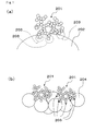
- the diameter of the supported catalyst particles 202 tends to be much larger than the diameter of the secondary particles 201 of soot as shown in Fig. 1(a) . Accordingly, this prior art has a problem that, due to few activity points 203 between the catalyst particles and the secondary particles of soot, soot combustion behavior by active oxygen induced by an oxide catalyst cannot be fully exerted. Accordingly, soot captured by the catalyst supporting honeycomb of this kind is hardly combusted, except for by forced regeneration using high temperature exhaust gases.
- an aim of the present invention is to reduce an increase with time in the pressure loss upon an influx of soot into catalyst supporting honeycombs in which a catalyst is supported, by allowing soot that has been flowed in to more easily contact with the catalyst with each other so as to improve the soot combustion behavior by active oxygen induced by the oxide catalyst.
- oxide catalyst particles are supported on a pillar-shaped honeycomb structured body primarily comprising inorganic fibers, in which a plurality of cells are formed in parallel with one another in a longitudinal direction with a cell wall interposed therebetween, and the average particle diameter of the oxide catalyst particles is set to 0.05 to 1.00 ⁇ m.
- cell walls of the catalyst supporting honeycomb function as filter for capturing soot.
- the average particle diameter of the oxide catalyst particles supported thereon is set to 0.05 to 1.00 ⁇ m, which is almost the same as an average particle diameter of the secondary particles of soot.
- the activity points between the secondary particles of soot and the catalyst particles can be increased as shown in Fig. 1(b) .
- the soot and the catalyst can easily contact with each other, with the result that the soot combustion behavior by active oxygen induced by the oxide catalyst can be improved.
- This behavior in addition to the forced regeneration of soot flowed into the catalyst supporting honeycomb, makes it easier to combust soot as compared with the catalyst supporting honeycomb of Patent Document 1.
- the catalyst supporting honeycomb can also be concretely configured by a honeycomb structured body in which a plurality of lamination members are laminated with one another in a longitudinal direction, and the lamination members are laminated so that the cells of each lamination member are aligned with the cells of the other lamination members.
- the porosity of the cell wall is 70% or more.
- the oxide catalyst is at least one member selected from the group consisting of CeO 2 , ZrO 2 , FeO 2 , Fe 2 O 3 , CuO, CuO 2 , Mn 2 O 3 , MnO, K 2 O, and a composite oxide represented by a composition formula A n B 1-n CO 3 (in which A represents La, Nd, Sm, Eu, Gd or Y; B represents an alkali metal or an alkali earth metal; C represents Mn, Co, Fe or Ni) as described in claim 5, a catalyst which is excellent in active oxygen delivery performance can be supported on the catalyst supporting honeycomb. As a result of this, the soot combustion function of the catalyst supporting honeycomb can be especially improved.
- the catalyst supporting honeycomb in which the oxide catalyst particles are supported on the cell walls, can show the same effects as those specifically described above as the effects of the catalyst supporting honeycombs according to claims 1 to 5.
- a method of manufacturing a catalyst supporting honeycomb which includes processes of: manufacturing a honeycomb structured body configured by a plurality of cells formed in parallel with one another in a longitudinal direction with a cell wall, which primarily comprises inorganic fibers, interposed therebetween; dispersing a solution of a precursor of a catalyst in a gas; flowing a gas containing the dispersed solution of the precursor of the catalyst into the honeycomb structured body; and heating the honeycomb structured body so that the precursor of the catalyst is formed into catalyst particles, it is possible to manufacture a catalyst supporting honeycomb which can show the same effects as those specifically described above as the effects of the catalyst supporting honeycombs according to claims 1 to 5.
- honeycomb structured body primarily comprising inorganic fibers according to a first embodiment of the present invention with reference to drawings.
- the honeycomb structured body according to the present embodiment is configured by inorganic fibers and inorganic material, and the inorganic fibers are fixed to each other through the inorganic material.
- portions where the inorganic fibers are fixed to each other are mainly intersection portions of the inorganic fibers, and the inorganic material is preferably present locally at the intersection portions of the organic fibers.
- the inorganic material fixes the intersection portions of the inorganic fibers by vitrification.
- the honeycomb structured body according to the present embodiment is an integral honeycomb structured body comprising a single member.
- Fig. 2 is a cross sectional diagram that schematically illustrates a portion of the inorganic fiber forming the honeycomb structured body according to the present embodiment.
- the cross sectional diagram shown in Fig. 2 is a cross sectional diagram obtained by cutting the crossing inorganic fibers in a length direction.
- inorganic material 62 When inorganic material 62 is fixed to an intersection portion of inorganic fibers 61 which form the honeycomb structured body as shown in Fig. 2 , the inorganic material 62 fixed to the intersection portion functions to bond the two inorganic fibers at the intersection portion.
- the fixing portion is present not only at one site but also at two or more sites per one inorganic fiber, causing complex intertwining of many fibers, and therefore, separation of the inorganic fibers can be avoided. Moreover, strength of the honeycomb structured body is improved.
- intersection portion of the inorganic fibers refers to an area within a distance of almost ten times of the fiber diameter of the inorganic fibers from the portion where inorganic fibers are most close to each other.
- the above-mentioned honeycomb structured body is configured by inorganic fibers and inorganic material.
- the inorganic fibers include: an oxide ceramic such as silica-alumina, mullite, alumina, silica, titania and zirconia; a nitride ceramic such as silicon nitride and boron nitride; a carbide ceramic such as silicon carbide; basalt, and the like.
- oxide ceramic such as silica-alumina, mullite, alumina, silica, titania and zirconia
- a nitride ceramic such as silicon nitride and boron nitride
- a carbide ceramic such as silicon carbide; basalt, and the like.
- the inorganic material includes inorganic material that melts at a temperature at which the inorganic fibers neither melt nor sublime.
- the inorganic material preferably includes inorganic material that melts at a temperature of the heat-resistant temperature of the inorganic fibers or lower.
- the heat resistance temperature of the inorganic fibers or the like for example, those inorganic materials which melt at a temperature of the heat-resistant temperature of the inorganic fibers or less may be used. More specifically, for example, in the case where alumina is used as the inorganic fibers, those inorganic materials which melt at 1300°C or less may be used.
- the inorganic material those containing silica are preferably used, and specific examples of the inorganic material containing silica include inorganic glass such as silicate glass, silicate alkali glass and borosilicate glass, and the like.
- the desirable lower limit is 70%
- the desirable upper limit is 95%.
- the porosity is less than 70%, soot hardly enters into inner portions of pores, and as a result, those catalysts supported on the inner portions of the cell walls of the honeycomb structured body tend not to contact with soot.
- the porosity is more than 95%, the ratio occupied by pores is increased, and therefore it becomes difficult to maintain the strength of the honeycomb structured body as a whole.
- an average pore diameter is not specifically limited, and the desirable lower limit is 10 ⁇ m, and the desirable upper limit is 100 ⁇ m.
- the average pore diameter is less than 10 ⁇ m, the catalyst is hardly supported on the inner portions of the cell walls, and also soot may not be filtered at the deep inside the cell walls, with the result that the soot is hardly made in contact with the catalyst supported on the inner portions of the cell walls.
- the average pore diameter is more than 100 ⁇ m, a catalyst or soot may easily pass through the pores, resulting in failure to function as a filter.
- the above-mentioned porosity and pore diameter can be measured through known methods, such as a measuring method using a mercury porosimeter, Archimedes method and a measuring method using a scanning electron microscope (SEM).
- the desirable lower limit is 30%
- the desirable upper limit is 60%.
- the aperture ratio is less than 30%
- the pressure loss may become high when exhaust gases flow into and out of the honeycomb structured body.
- the aperture ratio is more than 60%, the strength of the honeycomb structured body may be reduced.
- a method of manufacturing the honeycomb structured body includes process of: mixing inorganic fibers A with inorganic fibers B and/or inorganic particles C, both of which melt at a temperature at which the inorganic fibers A neither melt nor sublime; extrusion-molding a mixture obtained by the above-mentioned mixing process through a die in which predetermined holes are formed to form a pillar-shaped molded body with a number of cells formed in the longitudinal direction; and carrying out a heating treatment on the molded body at a temperature of the heat-resistant temperature of the inorganic fibers A or less and at the same time at a temperature of the softening temperature of the inorganic fibers B and/or the inorganic particles C or more.
- a mixing process is carried out by mixing the inorganic fibers A with the inorganic fibers B and/or the inorganic particles C, both of which melt at a temperature at which the inorganic fibers A neither melt nor sublime, so as to prepare a mixture.
- the same inorganic fibers exemplified in the description of the honeycomb structured body mentioned above can be used as the inorganic fibers A.
- the preferable examples thereof include at least one member selected from the group consisting of silicon carbide, alumina, basalt, silica, silica-alumina, titania and zirconia, because this arrangement makes it possible to manufacture a honeycomb structured body having excellent heat resistance.
- the inorganic fibers B and/or the inorganic particles C are not particularly limited as long as the inorganic fibers and/or the inorganic particles melt at a temperature at which the inorganic fibers A do not melt.
- examples of the inorganic fibers B include inorganic glass fibers comprising silicate glass, silicate alkali glass, borosilicate glass and the like, or the like
- examples of the inorganic particles C include inorganic glass particles comprising silicate glass, silicate alkali glass, borosilicate glass and the like, or the like.
- the blending ratio (weight ratio) between the inorganic fibers A and a total amount of the inorganic fibers B and the inorganic particles C preferably falls in the range of (2:8) to (8:2).
- the blending ratio of the inorganic fibers A is less than the above-mentioned range, the inorganic material tends to fix to the inorganic fibers in a manner as to coat the surface of the inorganic fibers, resulting in insufficient flexibility in the resulting honeycomb structured body.
- the blending ratio of the inorganic fibers A exceeds the above-mentioned range, the fixing portions between the inorganic fibers are reduced, resulting in insufficient strength in the resulting honeycomb structured body.
- a liquid medium such as water, or a dispersant may be added thereto, if necessary, so as to uniformly mix the inorganic fibers A with the inorganic fibers B and/or the inorganic particles C.
- an organic binder may be added thereto.
- organic binder examples include: an acrylic binder, ethyl cellulose, butyl cellosolve, polyvinyl alcohol and the like.
- organic binders may be used, or two or more kinds of these may be used in combination.
- a plasticizer, a lubricant, a molding auxiliary, a pore-forming agent and the like may be added thereto. With respect to the plasticizer and the lubricant, those conventionally used may be applied.
- the thus obtained mixture is preferably allowed to have such properties that the homogeneous composition is maintained for a long time and that the inorganic fibers and the like are prevented from precipitating, and further, the mixture is preferably allowed to have a degree of viscosity that can maintain the predetermined shape in the succeeding molding process.
- an extrusion-molding process is carried out on the mixture obtained in the above-mentioned mixing process.
- the mixture is continuously extruded by using a die in which predetermined holes are formed so as to form a pillar-shaped molded body with a large number of cells formed in the longitudinal direction.
- the apparatus to be used in the extrusion-molding process is not particularly limited, and for example, a single-axis screw-type extrusion-molding machine, a multi-axis screw-type extrusion-molding machine, a plunger-type molding machine and the like may be used. Among these, in particular, the plunger-type molding machine is preferably used. With reference to the drawings, the following description will discuss a plunger-type molding machine to be used in the present process and the application example thereof, although not limited to those systems.
- Fig. 3 is a cross-sectional diagram that schematically illustrates a plunger-type molding machine to be used for molding a pillar-shaped molded body.
- This plunger-type molding machine 80 is formed by a cylinder 81, a piston 83 provided with a mechanism capable of reciprocally moving between the front side and the rear side in the cylinder (horizontal direction in the figure), a die 84 that is attached to the tip of the cylinder and has holes formed therein for extrusion-molding a pillar-shaped molded body with a large number of cells formed in the longitudinal direction, and a mixture tank 82 placed on the upper portion of the cylinder 81, to which a pipe 85 is connected from the cylinder 81. Moreover, a shutter 86 is placed right below the mixture tank 82 so that the charging operation of the mixture from the mixture tank 82 can be interrupted.
- a screw 87 with blades 87a is attached to the pipe 85, and allowed to rotate by a motor 88.
- the size of the blade 87a is set to virtually the same as the diameter of the pipe so that the mixture 89 is hardly allowed to flow reversibly.
- the mixture prepared in the above-mentioned mixing process is loaded into the mixture tank 82.
- the shutter 86 is opened, and the mixture, obtained in the mixing process, is charged into the cylinder 81 from the mixture tank 82 by rotating the screw. At this time, the piston 83 is moved to the end portion of the cylinder 81 on the right side in Fig. 3 according to the amount of the charge.
- the shutter 86 is closed and the rotation of the screw 87 is simultaneously stopped.
- the shape of the cells to be formed through the extrusion-molding process can be desirably selected by changing the shape of holes to be formed in the die.
- the shape on the vertical cross section of each of the cells is not particularly limited to a tetragonal shape, and any desired shape such as a triangular shape, a hexagonal shape, an octagonal shape, a dodecagonal shape, a round shape, an elliptical shape and a star shape may be listed.
- molded bodies having various outer shapes can be manufactured by changing the shape of the die.
- the vertical cross-sectional shape of the honeycomb structured body is not limited to a round shape, and various shapes such as a rectangular shape may be used; however, it is preferable to use a shape enclosed only by a curved line or by curved lines and straight lines. Specific examples thereof include, in addition to a round shape, a rectangular pillar shape, an elongated round shape (racetrack shape), a shape in which one portion of a simple closed curved line such as a rectangular pillar shape or a racetrack shape has a recess portion (concave shape), and the like.
- heating treatment is carried out on the molded body obtained in the above-mentioned extrusion-molding process.
- the molded body is heated at a temperature of the heat-resistant temperature of the inorganic fibers A or less and at the same time at the softening temperature of the inorganic fibers B and/or the inorganic particles C or more; thus, a honeycomb structured body is obtained.
- the heating temperature is appropriately determined by taking into consideration the combination of the inorganic fibers A with the inorganic fibers B and/or the inorganic particles C.
- Examples of the heat-resistant temperature of the inorganic fibers A are given as follows: alumina > 1300°C, silica > 1000°C, silicon carbide > 1600°C, and silica-alumina > 1200°C.
- the specific heating temperature cannot be unconditionally determined because it depends on the heat-resistant temperature and the softening temperature of the inorganic fibers and the inorganic particles, and it is preferably set to 900 to 1050°C in the case where inorganic glass is used as the inorganic fibers B and/or the inorganic particles C.
- a cutting process for cutting the manufactured molded body into a predetermined length it is preferable to carry out a cutting process for cutting the manufactured molded body into a predetermined length, a drying process for removing moisture from the molded body and a degreasing process for removing organic materials from the molded body.
- the cutting member to be used in the cutting process is not particularly limited, and for example, a cutter having a blade formed in the cutting portion, a laser beam, a linear member, or the like may be used. Moreover, a cutter that uses a rotary disc for cutting may also be used.
- a molded body cutting machine provided with a cutting means such as a laser and a cutter is installed, and while the cutting means is being transferred at a speed synchronous to the extruding speed of the molding body, the molded body is cut by the cutting means.
- drying apparatus used for the drying process although not particularly limited, for example, a microwave heat drying apparatus, a hot-air drying apparatus, an infrared ray drying apparatus or the like may be used, and a plurality of these apparatuses may be used in combination.
- the drying process is preferably carried out at a set temperature in the range of 100 to 150°C for 5 to 60 minutes under the atmospheric condition.
- the arrangement is preferably made so that the hot air is directed to the molded body in parallel with the longitudinal direction thereof so as to allow the hot air to pass through the cells.
- the degreasing process is preferably carried out in an oxidizing atmosphere such as normal atmosphere so as to oxidatively decompose the organic substances.
- the degreasing furnace is not particularly limited, and a batch-type degreasing furnace may be used; however, in order to continuously carry out the process, a continuous furnace provided with a belt conveyor is preferably used.
- the degreasing process is preferably carried out by conducting a drying process at a set temperature in the range of 200 to 600°C under normal atmosphere for 1 to 5 hours.
- an acid treatment may be carried out on the pillar-shaped molded body manufactured through the above-mentioned method.
- the acid treatment is carried out by immersing the molded body in a solution such as a hydrochloric acid solution and a sulfuric acid solution.
- the concentration of the treatment solution is preferably in the range of 1 to 10 mol/l
- the treating time is preferably 0.5 to 24 hours
- the treatment temperature is preferably in the range of 70 to 100°C.
- the above-mentioned acid treatment process may be carried out during heating treatment processes. More specifically, the following processes are preferably carried out: a primary firing process is carried out at 950°C for 5 hours, and the acid treatment is then carried out, and a heating treatment is again carried out at 1050°C for 5 hours as a secondary firing process. These processes further improve the heat resisting property of the molded body.
- the lamination member for an end portion 10b is firstly laminated in the casing 11, and the honeycomb structured body 10a manufactured, for example, according to the present embodiment is installed thereon.
- the lamination member 10b for an end portion is laminated, and thereafter a pressing metal member is attached and fixed also on the other side the casing 11 so that the honeycomb structured body on which processes up to a canning process have been carried out can be manufactured.
- the material for the casing for example, metal materials such as stainless steel (SUS), aluminum and iron may be used.
- the shape of the casing is preferably a shape similar to the outer shape of the honeycomb structured body to be housed.
- the lamination member for an end portion it is preferable to laminate a lamination member for an end portion comprising metal with predetermined through holes formed therein. With this arrangement, it is possible to manufacture a honeycomb filter in which the lamination member for an end portion mainly comprising metal is laminated on both sides of the honeycomb structured body.
- a lamination member for an end portion a lamination member for an end portion comprising inorganic fibers may be laminated.
- the lamination member for an end portion comprising inorganic fibers may be manufactured by the same method as the above-mentioned method of manufacturing the honeycomb structured body, except that the shape of the holes formed in a die in the extrusion-molding process in the method for manufacturing the honeycomb structured body is changed so that a molded body having cells formed in a checkered pattern is manufactured, and the resulting molded body is thinly cut in the cutting process.
- the method for manufacturing the lamination member for an end portion comprising metal is described below.
- a laser machining process or a punching process is carried out on a porous metal plate mainly comprising metal having a thickness of 0.1 to 20 mm so that a lamination member for an end portion with through holes formed in a checkered pattern can be manufactured.
- an oxide catalyst is supported on the honeycomb structured body so that a catalyst supporting honeycomb is manufactured.
- a solution of a precursor of a catalyst is prepared.
- the precursor of the catalyst include those that become any of CeO 2 , ZrO 2 , FeO 2 , Fe 2 O 3 , CuO, CuO 2 , Mn 2 O 3 , MnO, K 2 O, and a composite oxide represented by a composition formula A n B 1-n CO 3 (in which A represents La, Nd, Sm, Eu, Gd or Y; B represents an alkali metal or an alkali earth metal; C represents Mn, Co, Fe or Ni), after such precursors are condensed, thermally decomposed, and crystallized in the later process.
- A represents La, Nd, Sm, Eu, Gd or Y
- B represents an alkali metal or an alkali earth metal
- C represents Mn, Co, Fe or Ni
- One kind of these precursors may be used, or two or more kinds thereof may be used in combination.
- nitrate salt, carbonate salt, acetate salt and the like containing a metal element of the oxide can be used, and the examples thereof include a metal complex body represented by a general formula M(OR 1 ) p (R 2 COCHCOR 3 ) q (in the formula, M represents one member selected from the group consisting of Ce, Zr, Fe, Cu, Mn and K; p and q each represents an integer number determined so that the metal complex has a 2 to 8 coordinate structure, and either p or q may be 0; when the number of each of R 1 , R 2 and R 3 is two or more, then R 1 , R 2 , R 3 may be respectively the same as or different.
- M represents one member selected from the group consisting of Ce, Zr, Fe, Cu, Mn and K
- p and q each represents an integer number determined so that the metal complex has a 2 to 8 coordinate structure, and either p or q may be 0; when the number of each of R 1 , R 2 and R 3 is
- R 1 and R 2 each represents an alkyl group having 1 to 6 carbon atoms
- R 3 represents an alkyl group having 1 to 6 carbon atoms and/or an alkoxy group having 1 to 16 carbon atoms), and the like.
- solvent include water, an organic solvent such as toluene and alcohol, and the like.
- the above-mentioned solution is dispersed in a gas by a known spraying method and the like.
- the dispersion is carried out in such a manner that the dispersed droplets have a constant size, then the particle diameter of the oxide catalyst to be supported on the honeycomb structured body in a later process can be adjusted to a constant size.
- the gas including the dispersed solution of the precursor is transported by a carrier gas to flow into one of the ends of the honeycomb structured body 10a.
- the influx speed of the carrier gas is preferably almost the same as the speed of actual exhaust gases from an engine and may be, for example, about 72,000 (1/h) in terms of space velocity.
- the carrier gas is flowed into one of the ends of the honeycomb structured body and flowed out from the adjacent cell after passing through a cell wall.
- the solution of the precursor dispersed and mixed in the carrier gas is adhered to the cell walls of the honeycomb structured body 10a.
- the precursor of the catalyst attached to the cell walls is condensed, thermally decomposed and crystallized, and is supported on the honeycomb structured body as an oxide catalyst.
- the oxide catalyst is supported preferably in such a manner that the carrier gas is flowed into the honeycomb structured body 10a while the honeycomb structured body 10a is heated so that adhesion of the solution of the precursor as well as condensation, thermal decomposition and crystallization of the precursor are performed simultaneously. With this arrangement, the precursor of the catalyst is adhered to the honeycomb structured body as catalyst particles, and thus tends to be more evenly supported.
- silica-alumina fibers configured by 72% of alumina and 28% of silica (average fiber length: 0.3 mm, average fiber diameter: 5 ⁇ m), 5.9% by weight of glass fibers (average fiber diameter: 9 ⁇ m, average fiber length: 0.1 mm), 17.0% by weight of methyl cellulose as organic binder, 4.6% by weight of acrylic resin, 7.8% by weight of a lubricant (UNILUB, made by NOF Corporation), 3.7% by weight of a glycerin and 49.2% by weight of water were mixed and sufficiently stirred so as to prepare a mixture.
- the mixture was charged into a cylinder of a plunger-type molding machine, and a piston was pressed and shoved into the die side so that the mixture was extruded through the die, thereby a raw molded body was manufactured.
- the raw molded body was then dried at 200°C for 3 hours by a microwave drying apparatus and a hot-air drying apparatus to remove moisture in the molded body.
- heating treatment was carried out on the molded body in an electric furnace at 400°C for 3 hours so that organic matters contained in the molded body were removed.
- a heating treatment was carried out on the molded body in a firing furnace at 950°C for 5 hours, and thereafter, acid treatment was carried out by immersing the molded body into a 4 mol/L HCl solution of 90°C for 1 hour and further a heating treatment was carried out at 1050°C for 5 hours so that a honeycomb structured body primarily comprising inorganic fibers having a size of ⁇ 30 mm x 48 mm was obtained.
- the porosity of the cell walls was 93%
- the average pore diameter of the cell walls was 45 ⁇ m
- the cell density was 8.5 cells/cm 2 (55 cpsi); and the thickness of the cell walls was 1.27 mm.
- a metal plate made of Ni-Cr alloy was processed in a round disk shape having a size of ⁇ 30 mm x 1 mm, and holes were formed therein by a laser processing so that two plates of lamination members for an end portion, having different sealed portions with one another, of the honeycomb structured body were manufactured.
- One of the lamination members for an end portion was installed in the cylindrical casing (can-type), and the honeycomb structured body was placed thereon in such a manner that the positions of holes of the lamination member for an end portion fit to the positions of cells of the honeycomb structured body. Further, the other lamination member for an end portion was also installed thereon in such a manner that the positions of holes thereof fit to the positions of the cells of the honeycomb structured body, and the lamination member for an end portion was welded to the casing, thereby a honeycomb filter with a length of 50 mm was manufactured.
- an oxide catalyst was supported on the obtained honeycomb structured body (honeycomb filter).
- cerium nitrate was dissolved in water to prepare a solution of a precursor of CeO 2 .
- a gas in which the solution of the precursor was dispersed was transported by a carrier gas so as to be flowed into one of the ends of the honeycomb filter.
- the speed of the carrier gas was adjusted to a space velocity of 72000 (1/h).
- a catalyst supporting honeycomb in which CeO 2 having an average particle diameter of 0.1 ⁇ m are supported on the honeycomb structured body comprising inorganic fibers was obtained.
- the amount of the CeO 2 was adjusted to 20 g per 1L of the catalyst supporting honeycomb. Measurement of the average particle diameter of the oxide catalyst was performed by using SEM photographs.
- the raw molded body was dried by using a microwave drying apparatus and the like to form a dried body, followed by filling of a plug material paste having the same composition as that of the raw molded body into the predetermined cells. Further, after again dried by a drying apparatus, the resulting product was degreased at 400°C and then fired at 2200°C under a normal-pressure argon atmosphere for 3 hours so as to manufacture a honeycomb structured body formed by a silicon carbide sintered body with a porosity of cell walls of 42%, an average pore diameter of 11.0 ⁇ m, a size of ⁇ 30 mm x 50 mm, the number of cells of 46.5 pcs/cm 2 (300 cpsi) and a thickness of the cell walls of 0.25 mm.
- an oxide catalyst was supported on the honeycomb structured body in the same manner as in Example 1, thereby a catalyst supporting honeycomb was obtained.
- the average particle diameter of CeO 2 was 0.1 ⁇ m, and the support amount was 20 g/L
- a honeycomb structured body was manufactured in the same manner as Example 1.
- the honeycomb structured body was immersed in a solution containing 10 g of CeO 2 , 40 ml of water and a pH adjusting agent for 5 minutes, and a firing treatment was carried out on the resulting honeycomb structured body at 500°C so that a honeycomb structured body on which a catalyst is supported, having CeO 2 supported thereon was manufactured.
- the average particle diameter of the supported CeO 2 was 2 ⁇ m, and the support amount was 20 g/L.
- the thus obtained honeycomb structured body on which a catalyst is supported was installed in the casing together with the lamination members for an end portion in the same manner as in Example 1, thereby a catalyst supporting honeycomb was manufactured.
- a 2L common rail engine was driven at a rotational speed of 1500 rpm with a torque of 47 Nm, and exhaust gases thus generated were allowed to flow into the catalyst supporting honeycomb that was placed in a branched pipe.
- the catalyst supporting honeycomb was heated up to 350°C by the heating device, and the flow rate of the exhaust gases was set to 2.9 cm/s for the catalyst supporting honeycomb according to Comparative Example 1, and was set to 18 cm/s for the catalyst supporting honeycomb according to Example 1 and Comparative Example 2 so that a differential pressure between the front and the back of the respective catalyst supporting honeycombs was measured.
- the results are as shown in Fig. 5 .
- the catalyst supporting honeycomb of Example 1 which mainly comprises inorganic fibers, has a high porosity, and therefore an increase with time in pressure loss in relation to the amount of soot that had been flowed in can be maintained at a low level. This is because, by allowing soot to flow into deep portions of the cell walls, soot can contact with the catalysts supported inside the cell walls. As a result of this, the soot flowed into the catalyst supporting honeycomb can be continuously burned more easily, and thus a time period before forced regeneration can be prolonged.
- an average particle diameter of the catalyst is 0.05 to 1.00 ⁇ m, which is smaller as compared with the catalyst supporting honeycomb of Comparative Example 2.
- the honeycomb structured body 10a formed by a single member was exemplified.
- a honeycomb structured body may be configured by a plurality of plate-like lamination members which are laminated in such a manner that the cells of each lamination member are aligned with the cells of the other lamination members.
Landscapes
- Chemical & Material Sciences (AREA)
- Engineering & Computer Science (AREA)
- Chemical Kinetics & Catalysis (AREA)
- Organic Chemistry (AREA)
- Materials Engineering (AREA)
- Health & Medical Sciences (AREA)
- Combustion & Propulsion (AREA)
- Biomedical Technology (AREA)
- Environmental & Geological Engineering (AREA)
- Analytical Chemistry (AREA)
- General Chemical & Material Sciences (AREA)
- Oil, Petroleum & Natural Gas (AREA)
- Thermal Sciences (AREA)
- Physics & Mathematics (AREA)
- Catalysts (AREA)
- Magnetic Resonance Imaging Apparatus (AREA)
- Superconductors And Manufacturing Methods Therefor (AREA)
- Transition And Organic Metals Composition Catalysts For Addition Polymerization (AREA)
Abstract
Description
- The present invention relates to a catalyst supporting honeycomb and a method of manufacturing the same.
- There has been known a catalyst supporting honeycomb which converts exhaust gases by allowing the exhaust gases to contact with a catalyst supported on cell walls of a honeycomb structured body which is mainly made of inorganic fibers. With regard to a catalyst supporting honeycomb disclosed in
Patent Document 1, a catalyst is supported on a honeycomb structured body by impregnating the honeycomb structured body in a catalyst solution in a slurry state, and then heating the honeycomb structured body. - Patent Document 1:
WO 2007/10643 A1 - Normally, the average diameter of secondary particles of soot in exhaust gases is about 0.1 µm. However, in the catalyst supporting honeycomb disclosed in
Patent Document 1, since the honeycomb structured body has been impregnated in the catalyst solution in a slurry state, the diameter of the supportedcatalyst particles 202 tends to be much larger than the diameter of thesecondary particles 201 of soot as shown inFig. 1(a) . Accordingly, this prior art has a problem that, due to few activity points 203 between the catalyst particles and the secondary particles of soot, soot combustion behavior by active oxygen induced by an oxide catalyst cannot be fully exerted.
Accordingly, soot captured by the catalyst supporting honeycomb of this kind is hardly combusted, except for by forced regeneration using high temperature exhaust gases. Therefore, soot is easily accumulated on cell walls, causing a problem of increase with time in the pressure loss due to an influx of soot into the catalyst supporting honeycomb.
In light of the above-mentioned points, an aim of the present invention is to reduce an increase with time in the pressure loss upon an influx of soot into catalyst supporting honeycombs in which a catalyst is supported, by allowing soot that has been flowed in to more easily contact with the catalyst with each other so as to improve the soot combustion behavior by active oxygen induced by the oxide catalyst. - In order to achieve the above-mentioned aim, in the catalyst supporting honeycomb described in
claim 1, oxide catalyst particles are supported on a pillar-shaped honeycomb structured body primarily comprising inorganic fibers, in which a plurality of cells are formed in parallel with one another in a longitudinal direction with a cell wall interposed therebetween, and the average particle diameter of the oxide catalyst particles is set to 0.05 to 1.00 µm.
In the catalyst supporting honeycomb described inclaim 1, since either of two end portions of each cell is sealed, cell walls of the catalyst supporting honeycomb function as filter for capturing soot.
In those catalyst supporting honeycombs, the average particle diameter of the oxide catalyst particles supported thereon is set to 0.05 to 1.00 µm, which is almost the same as an average particle diameter of the secondary particles of soot. Therefore, the activity points between the secondary particles of soot and the catalyst particles can be increased as shown inFig. 1(b) . In other words, the soot and the catalyst can easily contact with each other, with the result that the soot combustion behavior by active oxygen induced by the oxide catalyst can be improved.
This behavior, in addition to the forced regeneration of soot flowed into the catalyst supporting honeycomb, makes it easier to combust soot as compared with the catalyst supporting honeycomb ofPatent Document 1. As a result, it is possible to reduce an increase with time in the pressure loss upon an influx of soot.
Meanwhile, even in the case where the end portion is not sealed as described inclaim 1, the exhaust gas converting performance can be improved due to the increased chance of contact between exhaust gases and the catalyst. - Moreover, as described in claim 3, the catalyst supporting honeycomb can also be concretely configured by a honeycomb structured body in which a plurality of lamination members are laminated with one another in a longitudinal direction, and the lamination members are laminated so that the cells of each lamination member are aligned with the cells of the other lamination members.
Moreover, in the catalyst supporting honeycomb described in claim 4, the porosity of the cell wall is 70% or more. With this structure, soot can be flowed into deep portions of the cell walls. Accordingly, the catalyst supported inside the cell walls can be contacted with the soot, resulting in improved combustion of the soot that has flowed into the catalyst supporting honeycomb. This effect makes it possible to extend a time period during which soot is flowed into deep portions of the cell walls, and consequently a time period before a surge of pressure loss can be prolonged. - Further, when the oxide catalyst is at least one member selected from the group consisting of CeO2, ZrO2, FeO2, Fe2O3, CuO, CuO2, Mn2O3, MnO, K2O, and a composite oxide represented by a composition formula AnB1-nCO3 (in which A represents La, Nd, Sm, Eu, Gd or Y; B represents an alkali metal or an alkali earth metal; C represents Mn, Co, Fe or Ni) as described in claim 5, a catalyst which is excellent in active oxygen delivery performance can be supported on the catalyst supporting honeycomb. As a result of this, the soot combustion function of the catalyst supporting honeycomb can be especially improved.
- Furthermore, when a gas containing a dispersed solution of a precursor of an oxide catalyst is flowed into a pillar-shaped honeycomb structured body configured by a plurality of cells formed in parallel with one another in a longitudinal direction with a cell wall, which primarily comprises inorganic fibers, interposed therebetween as described in claim 6, the catalyst supporting honeycomb, in which the oxide catalyst particles are supported on the cell walls, can show the same effects as those specifically described above as the effects of the catalyst supporting honeycombs according to
claims 1 to 5. - Moreover, according to a method of manufacturing a catalyst supporting honeycomb which includes processes of: manufacturing a honeycomb structured body configured by a plurality of cells formed in parallel with one another in a longitudinal direction with a cell wall, which primarily comprises inorganic fibers, interposed therebetween; dispersing a solution of a precursor of a catalyst in a gas; flowing a gas containing the dispersed solution of the precursor of the catalyst into the honeycomb structured body; and heating the honeycomb structured body so that the precursor of the catalyst is formed into catalyst particles, it is possible to manufacture a catalyst supporting honeycomb which can show the same effects as those specifically described above as the effects of the catalyst supporting honeycombs according to
claims 1 to 5. - In the following, a plurality of embodiments of the present invention are described with reference to drawings.
- The following description will discuss a honeycomb structured body primarily comprising inorganic fibers according to a first embodiment of the present invention with reference to drawings.
The honeycomb structured body according to the present embodiment is configured by inorganic fibers and inorganic material, and the inorganic fibers are fixed to each other through the inorganic material. Here, portions where the inorganic fibers are fixed to each other are mainly intersection portions of the inorganic fibers, and the inorganic material is preferably present locally at the intersection portions of the organic fibers. Preferably, the inorganic material fixes the intersection portions of the inorganic fibers by vitrification. Here, the honeycomb structured body according to the present embodiment is an integral honeycomb structured body comprising a single member. -
Fig. 2 is a cross sectional diagram that schematically illustrates a portion of the inorganic fiber forming the honeycomb structured body according to the present embodiment. Here, the cross sectional diagram shown inFig. 2 is a cross sectional diagram obtained by cutting the crossing inorganic fibers in a length direction. - When
inorganic material 62 is fixed to an intersection portion ofinorganic fibers 61 which form the honeycomb structured body as shown inFig. 2 , theinorganic material 62 fixed to the intersection portion functions to bond the two inorganic fibers at the intersection portion. The fixing portion is present not only at one site but also at two or more sites per one inorganic fiber, causing complex intertwining of many fibers, and therefore, separation of the inorganic fibers can be avoided. Moreover, strength of the honeycomb structured body is improved. - In the case where the
inorganic material 62 is locally present at the intersection portions ofinorganic fibers 61, in many of theinorganic fibers 61, intersection portions with otherorganic fibers 61 are coated with theorganic material 62, and almost no inorganic material is fixed to most of the rest portions of theinorganic fibers 61.
Here, the intersection portion of the inorganic fibers refers to an area within a distance of almost ten times of the fiber diameter of the inorganic fibers from the portion where inorganic fibers are most close to each other. - The above-mentioned honeycomb structured body is configured by inorganic fibers and inorganic material. Examples of the inorganic fibers include: an oxide ceramic such as silica-alumina, mullite, alumina, silica, titania and zirconia; a nitride ceramic such as silicon nitride and boron nitride; a carbide ceramic such as silicon carbide; basalt, and the like. Each of these materials may be used alone, or two or more of them may be used in combination
- An example of the inorganic material includes inorganic material that melts at a temperature at which the inorganic fibers neither melt nor sublime. Moreover, the inorganic material preferably includes inorganic material that melts at a temperature of the heat-resistant temperature of the inorganic fibers or lower.
Here, in consideration of the temperature at which the inorganic fibers to be combined melt or sublime, the heat resistance temperature of the inorganic fibers or the like, for example, those inorganic materials which melt at a temperature of the heat-resistant temperature of the inorganic fibers or less may be used. More specifically, for example, in the case where alumina is used as the inorganic fibers, those inorganic materials which melt at 1300°C or less may be used.
With respect to the inorganic material, those containing silica are preferably used, and specific examples of the inorganic material containing silica include inorganic glass such as silicate glass, silicate alkali glass and borosilicate glass, and the like. - With respect to the porosity of the cell walls of the honeycomb structured body according to the present embodiment, the desirable lower limit is 70%, and the desirable upper limit is 95%. When the porosity is less than 70%, soot hardly enters into inner portions of pores, and as a result, those catalysts supported on the inner portions of the cell walls of the honeycomb structured body tend not to contact with soot. On the other hand, when the porosity is more than 95%, the ratio occupied by pores is increased, and therefore it becomes difficult to maintain the strength of the honeycomb structured body as a whole.
- In the honeycomb structured body according to the present embodiment, an average pore diameter is not specifically limited, and the desirable lower limit is 10 µm, and the desirable upper limit is 100 µm. When the average pore diameter is less than 10 µm, the catalyst is hardly supported on the inner portions of the cell walls, and also soot may not be filtered at the deep inside the cell walls, with the result that the soot is hardly made in contact with the catalyst supported on the inner portions of the cell walls. On the other hand, when the average pore diameter is more than 100 µm, a catalyst or soot may easily pass through the pores, resulting in failure to function as a filter.
Here, the above-mentioned porosity and pore diameter can be measured through known methods, such as a measuring method using a mercury porosimeter, Archimedes method and a measuring method using a scanning electron microscope (SEM). - With regard to the aperture ratio of the honeycomb structured body according to the present embodiment, the desirable lower limit is 30%, and the desirable upper limit is 60%. When the aperture ratio is less than 30%, the pressure loss may become high when exhaust gases flow into and out of the honeycomb structured body. When the aperture ratio is more than 60%, the strength of the honeycomb structured body may be reduced.
- A method of manufacturing the honeycomb structured body according to the present embodiment includes process of: mixing inorganic fibers A with inorganic fibers B and/or inorganic particles C, both of which melt at a temperature at which the inorganic fibers A neither melt nor sublime; extrusion-molding a mixture obtained by the above-mentioned mixing process through a die in which predetermined holes are formed to form a pillar-shaped molded body with a number of cells formed in the longitudinal direction; and carrying out a heating treatment on the molded body at a temperature of the heat-resistant temperature of the inorganic fibers A or less and at the same time at a temperature of the softening temperature of the inorganic fibers B and/or the inorganic particles C or more.
- The following description will discuss the above-mentioned manufacturing method of the honeycomb structured body in order of the processes. First, a mixing process is carried out by mixing the inorganic fibers A with the inorganic fibers B and/or the inorganic particles C, both of which melt at a temperature at which the inorganic fibers A neither melt nor sublime, so as to prepare a mixture.
- The same inorganic fibers exemplified in the description of the honeycomb structured body mentioned above can be used as the inorganic fibers A. The preferable examples thereof include at least one member selected from the group consisting of silicon carbide, alumina, basalt, silica, silica-alumina, titania and zirconia, because this arrangement makes it possible to manufacture a honeycomb structured body having excellent heat resistance.
- The inorganic fibers B and/or the inorganic particles C are not particularly limited as long as the inorganic fibers and/or the inorganic particles melt at a temperature at which the inorganic fibers A do not melt. Specifically, examples of the inorganic fibers B include inorganic glass fibers comprising silicate glass, silicate alkali glass, borosilicate glass and the like, or the like, and examples of the inorganic particles C include inorganic glass particles comprising silicate glass, silicate alkali glass, borosilicate glass and the like, or the like.
- When the inorganic fibers A is mixed with the inorganic fibers B and/or the inorganic particles C, the blending ratio (weight ratio) between the inorganic fibers A and a total amount of the inorganic fibers B and the inorganic particles C preferably falls in the range of (2:8) to (8:2). When the blending ratio of the inorganic fibers A is less than the above-mentioned range, the inorganic material tends to fix to the inorganic fibers in a manner as to coat the surface of the inorganic fibers, resulting in insufficient flexibility in the resulting honeycomb structured body. In contrast, when the blending ratio of the inorganic fibers A exceeds the above-mentioned range, the fixing portions between the inorganic fibers are reduced, resulting in insufficient strength in the resulting honeycomb structured body.
- Here, in preparation of the above-mentioned mixture, a liquid medium such as water, or a dispersant may be added thereto, if necessary, so as to uniformly mix the inorganic fibers A with the inorganic fibers B and/or the inorganic particles C. Moreover, an organic binder may be added thereto. When the inorganic binder is added, the inorganic fibers A can be surely entangled with the inorganic fibers B and/or the inorganic particles C so that, even prior to a firing process, the inorganic fibers B and/or the inorganic particles C are made to be hardly drawn off from the inorganic fibers A; thus, it becomes possible to more surely fix the inorganic fibers A to one another.
- Examples of the organic binder include: an acrylic binder, ethyl cellulose, butyl cellosolve, polyvinyl alcohol and the like. One kind of these organic binders may be used, or two or more kinds of these may be used in combination. In addition, if necessary, a plasticizer, a lubricant, a molding auxiliary, a pore-forming agent and the like may be added thereto. With respect to the plasticizer and the lubricant, those conventionally used may be applied.
- The thus obtained mixture is preferably allowed to have such properties that the homogeneous composition is maintained for a long time and that the inorganic fibers and the like are prevented from precipitating, and further, the mixture is preferably allowed to have a degree of viscosity that can maintain the predetermined shape in the succeeding molding process.
- Next, an extrusion-molding process is carried out on the mixture obtained in the above-mentioned mixing process. In this extrusion-molding process, the mixture is continuously extruded by using a die in which predetermined holes are formed so as to form a pillar-shaped molded body with a large number of cells formed in the longitudinal direction.
- The apparatus to be used in the extrusion-molding process is not particularly limited, and for example, a single-axis screw-type extrusion-molding machine, a multi-axis screw-type extrusion-molding machine, a plunger-type molding machine and the like may be used. Among these, in particular, the plunger-type molding machine is preferably used.
With reference to the drawings, the following description will discuss a plunger-type molding machine to be used in the present process and the application example thereof, although not limited to those systems. -
Fig. 3 is a cross-sectional diagram that schematically illustrates a plunger-type molding machine to be used for molding a pillar-shaped molded body. - This plunger-
type molding machine 80 is formed by acylinder 81, apiston 83 provided with a mechanism capable of reciprocally moving between the front side and the rear side in the cylinder (horizontal direction in the figure), a die 84 that is attached to the tip of the cylinder and has holes formed therein for extrusion-molding a pillar-shaped molded body with a large number of cells formed in the longitudinal direction, and amixture tank 82 placed on the upper portion of thecylinder 81, to which apipe 85 is connected from thecylinder 81. Moreover, ashutter 86 is placed right below themixture tank 82 so that the charging operation of the mixture from themixture tank 82 can be interrupted. Here, ascrew 87 withblades 87a is attached to thepipe 85, and allowed to rotate by amotor 88. The size of theblade 87a is set to virtually the same as the diameter of the pipe so that themixture 89 is hardly allowed to flow reversibly. The mixture prepared in the above-mentioned mixing process is loaded into themixture tank 82. - In manufacturing a molded body by using the plunger-
type molding machine 80, first, theshutter 86 is opened, and the mixture, obtained in the mixing process, is charged into thecylinder 81 from themixture tank 82 by rotating the screw. At this time, thepiston 83 is moved to the end portion of thecylinder 81 on the right side inFig. 3 according to the amount of the charge.
When thecylinder 81 is filled in with the mixture, theshutter 86 is closed and the rotation of thescrew 87 is simultaneously stopped. When thepiston 83 is pressed and shoved into the die side with the inside of thecylinder 81 filled with themixture 89, the mixture is extruded through the die 84 so that a pillar-shaped molded body in which a plurality of cells are formed with a wall portion therebetween is continuously formed. At this time, according to the shape of the hole formed in the die, cells having the corresponding shape are formed. By repeating these processes, a molded body can be manufactured. Depending on the viscosity and the like, a molded body can be continuously manufactured, by rotating thescrew 87 while thecylinder 83 is stopped.
Here, in the plunger-type molding machine 80 illustrated inFig. 3 , anoil cylinder 80 is used as the driving source used for shifting thepiston 83; however, an air cylinder may be used, or a ball screw or the like may also be used. - The shape of the cells to be formed through the extrusion-molding process can be desirably selected by changing the shape of holes to be formed in the die.
The shape on the vertical cross section of each of the cells is not particularly limited to a tetragonal shape, and any desired shape such as a triangular shape, a hexagonal shape, an octagonal shape, a dodecagonal shape, a round shape, an elliptical shape and a star shape may be listed. - Moreover, molded bodies having various outer shapes can be manufactured by changing the shape of the die. The vertical cross-sectional shape of the honeycomb structured body is not limited to a round shape, and various shapes such as a rectangular shape may be used; however, it is preferable to use a shape enclosed only by a curved line or by curved lines and straight lines. Specific examples thereof include, in addition to a round shape, a rectangular pillar shape, an elongated round shape (racetrack shape), a shape in which one portion of a simple closed curved line such as a rectangular pillar shape or a racetrack shape has a recess portion (concave shape), and the like.
- Next, heating treatment is carried out on the molded body obtained in the above-mentioned extrusion-molding process. In this heating treatment process, the molded body is heated at a temperature of the heat-resistant temperature of the inorganic fibers A or less and at the same time at the softening temperature of the inorganic fibers B and/or the inorganic particles C or more; thus, a honeycomb structured body is obtained.
- By carrying out this heating treatment, it is possible to manufacture a honeycomb structured body in which the inorganic fibers A are firmly fixed to one another through an inorganic material comprising the same material as the inorganic fibers B and/or the inorganic particles C, and most of the firmly fixed portions are the intersections of the inorganic fibers A, and the inorganic materials comprising the same material as the inorganic fibers B and/or the inorganic particles C are locally present at the intersections.
Here, the heating temperature is appropriately determined by taking into consideration the combination of the inorganic fibers A with the inorganic fibers B and/or the inorganic particles C.
Examples of the heat-resistant temperature of the inorganic fibers A are given as follows: alumina > 1300°C, silica > 1000°C, silicon carbide > 1600°C, and silica-alumina > 1200°C. - The specific heating temperature cannot be unconditionally determined because it depends on the heat-resistant temperature and the softening temperature of the inorganic fibers and the inorganic particles, and it is preferably set to 900 to 1050°C in the case where inorganic glass is used as the inorganic fibers B and/or the inorganic particles C.
- Additionally, prior to the heating treatment process, it is preferable to carry out a cutting process for cutting the manufactured molded body into a predetermined length, a drying process for removing moisture from the molded body and a degreasing process for removing organic materials from the molded body.
- The cutting member to be used in the cutting process is not particularly limited, and for example, a cutter having a blade formed in the cutting portion, a laser beam, a linear member, or the like may be used. Moreover, a cutter that uses a rotary disc for cutting may also be used.
- Moreover, another preferable cutting method is proposed in which to the end to which the molded body molded in the extrusion-molding process is transferred, a molded body cutting machine provided with a cutting means such as a laser and a cutter is installed, and while the cutting means is being transferred at a speed synchronous to the extruding speed of the molding body, the molded body is cut by the cutting means.
By using the cutting apparatus having the above-mentioned mechanism, it is possible to carry out the cutting process continuously, and consequently to improve the mass productivity. - With respect to the drying apparatus used for the drying process, although not particularly limited, for example, a microwave heat drying apparatus, a hot-air drying apparatus, an infrared ray drying apparatus or the like may be used, and a plurality of these apparatuses may be used in combination.
- For example, in the case of using a hot-air drying apparatus, the drying process is preferably carried out at a set temperature in the range of 100 to 150°C for 5 to 60 minutes under the atmospheric condition. In this case, the arrangement is preferably made so that the hot air is directed to the molded body in parallel with the longitudinal direction thereof so as to allow the hot air to pass through the cells. By allowing the hot air to pass through the cells of the molded body, the drying process of the molded body is carried out efficiently.
- Normally, the degreasing process is preferably carried out in an oxidizing atmosphere such as normal atmosphere so as to oxidatively decompose the organic substances. The degreasing furnace is not particularly limited, and a batch-type degreasing furnace may be used; however, in order to continuously carry out the process, a continuous furnace provided with a belt conveyor is preferably used. The degreasing process is preferably carried out by conducting a drying process at a set temperature in the range of 200 to 600°C under normal atmosphere for 1 to 5 hours.
- In the method for manufacturing the honeycomb structured body according to the present embodiment, an acid treatment may be carried out on the pillar-shaped molded body manufactured through the above-mentioned method. By carrying out the acid treatment, the heat resistance of the molded body can be improved. The acid treatment is carried out by immersing the molded body in a solution such as a hydrochloric acid solution and a sulfuric acid solution.
- With respect to the conditions of the acid treatment, in the case where inorganic glass is used as the inorganic material, the concentration of the treatment solution is preferably in the range of 1 to 10 mol/l, the treating time is preferably 0.5 to 24 hours, and the treatment temperature is preferably in the range of 70 to 100°C. By carrying out the acid treatment under these conditions, components other than silica are eluted so that the heat resistance of the molded body is consequently improved.
- The above-mentioned acid treatment process may be carried out during heating treatment processes. More specifically, the following processes are preferably carried out: a primary firing process is carried out at 950°C for 5 hours, and the acid treatment is then carried out, and a heating treatment is again carried out at 1050°C for 5 hours as a secondary firing process. These processes further improve the heat resisting property of the molded body.
- In the present embodiment, by laminating a honeycomb structured body and a lamination member for an end portion, it is possible to manufacture a honeycomb filter functioning as a filter, in which either of two end portions of each cell is sealed.
- More specifically, as illustrated in
Fig. 4(b) , by using a cylindrical casing 11 (can-type metal container) with a pressing metal member on one side, the lamination member for anend portion 10b is firstly laminated in thecasing 11, and the honeycomb structuredbody 10a manufactured, for example, according to the present embodiment is installed thereon. Lastly, thelamination member 10b for an end portion is laminated, and thereafter a pressing metal member is attached and fixed also on the other side thecasing 11 so that the honeycomb structured body on which processes up to a canning process have been carried out can be manufactured. With respect to the material for the casing, for example, metal materials such as stainless steel (SUS), aluminum and iron may be used. Although not particularly limited, the shape of the casing is preferably a shape similar to the outer shape of the honeycomb structured body to be housed. - With respect to the lamination member for an end portion, it is preferable to laminate a lamination member for an end portion comprising metal with predetermined through holes formed therein. With this arrangement, it is possible to manufacture a honeycomb filter in which the lamination member for an end portion mainly comprising metal is laminated on both sides of the honeycomb structured body.
- As the lamination member for an end portion, a lamination member for an end portion comprising inorganic fibers may be laminated. The lamination member for an end portion comprising inorganic fibers may be manufactured by the same method as the above-mentioned method of manufacturing the honeycomb structured body, except that the shape of the holes formed in a die in the extrusion-molding process in the method for manufacturing the honeycomb structured body is changed so that a molded body having cells formed in a checkered pattern is manufactured, and the resulting molded body is thinly cut in the cutting process.
- The method for manufacturing the lamination member for an end portion comprising metal is described below.
A laser machining process or a punching process is carried out on a porous metal plate mainly comprising metal having a thickness of 0.1 to 20 mm so that a lamination member for an end portion with through holes formed in a checkered pattern can be manufactured.
Thereafter, an oxide catalyst is supported on the honeycomb structured body so that a catalyst supporting honeycomb is manufactured. - First, a solution of a precursor of a catalyst is prepared. Preferable examples of the precursor of the catalyst include those that become any of CeO2, ZrO2, FeO2, Fe2O3, CuO, CuO2, Mn2O3, MnO, K2O, and a composite oxide represented by a composition formula AnB1-nCO3 (in which A represents La, Nd, Sm, Eu, Gd or Y; B represents an alkali metal or an alkali earth metal; C represents Mn, Co, Fe or Ni), after such precursors are condensed, thermally decomposed, and crystallized in the later process. One kind of these precursors may be used, or two or more kinds thereof may be used in combination. More specifically, for example, nitrate salt, carbonate salt, acetate salt and the like containing a metal element of the oxide can be used, and the examples thereof include a metal complex body represented by a general formula M(OR1)p(R2COCHCOR3)q (in the formula, M represents one member selected from the group consisting of Ce, Zr, Fe, Cu, Mn and K; p and q each represents an integer number determined so that the metal complex has a 2 to 8 coordinate structure, and either p or q may be 0; when the number of each of R1, R2 and R3 is two or more, then R1, R2, R3 may be respectively the same as or different. R1 and R2 each represents an alkyl group having 1 to 6 carbon atoms, and R3 represents an alkyl group having 1 to 6 carbon atoms and/or an alkoxy group having 1 to 16 carbon atoms), and the like. Examples of solvent include water, an organic solvent such as toluene and alcohol, and the like.
- The above-mentioned solution is dispersed in a gas by a known spraying method and the like. When the dispersion is carried out in such a manner that the dispersed droplets have a constant size, then the particle diameter of the oxide catalyst to be supported on the honeycomb structured body in a later process can be adjusted to a constant size.
- Next, the gas including the dispersed solution of the precursor is transported by a carrier gas to flow into one of the ends of the honeycomb structured
body 10a. At this time, the influx speed of the carrier gas is preferably almost the same as the speed of actual exhaust gases from an engine and may be, for example, about 72,000 (1/h) in terms of space velocity. The carrier gas is flowed into one of the ends of the honeycomb structured body and flowed out from the adjacent cell after passing through a cell wall. On this occasion, the solution of the precursor dispersed and mixed in the carrier gas is adhered to the cell walls of the honeycomb structuredbody 10a. - Further, by heating the honeycomb structured body at a temperature of 300 to 800°C, the precursor of the catalyst attached to the cell walls is condensed, thermally decomposed and crystallized, and is supported on the honeycomb structured body as an oxide catalyst.
- The oxide catalyst is supported preferably in such a manner that the carrier gas is flowed into the honeycomb structured
body 10a while the honeycomb structuredbody 10a is heated so that adhesion of the solution of the precursor as well as condensation, thermal decomposition and crystallization of the precursor are performed simultaneously. With this arrangement, the precursor of the catalyst is adhered to the honeycomb structured body as catalyst particles, and thus tends to be more evenly supported. - First, 11.8% by weight of silica-alumina fibers configured by 72% of alumina and 28% of silica (average fiber length: 0.3 mm, average fiber diameter: 5 µm), 5.9% by weight of glass fibers (average fiber diameter: 9 µm, average fiber length: 0.1 mm), 17.0% by weight of methyl cellulose as organic binder, 4.6% by weight of acrylic resin, 7.8% by weight of a lubricant (UNILUB, made by NOF Corporation), 3.7% by weight of a glycerin and 49.2% by weight of water were mixed and sufficiently stirred so as to prepare a mixture.
Next, the mixture was charged into a cylinder of a plunger-type molding machine, and a piston was pressed and shoved into the die side so that the mixture was extruded through the die, thereby a raw molded body was manufactured. The raw molded body was then dried at 200°C for 3 hours by a microwave drying apparatus and a hot-air drying apparatus to remove moisture in the molded body. Next, heating treatment was carried out on the molded body in an electric furnace at 400°C for 3 hours so that organic matters contained in the molded body were removed. - Further, a heating treatment was carried out on the molded body in a firing furnace at 950°C for 5 hours, and thereafter, acid treatment was carried out by immersing the molded body into a 4 mol/L HCl solution of 90°C for 1 hour and further a heating treatment was carried out at 1050°C for 5 hours so that a honeycomb structured body primarily comprising inorganic fibers having a size of φ30 mm x 48 mm was obtained. In this honeycomb structured body, the porosity of the cell walls was 93%, the average pore diameter of the cell walls was 45 µm, the cell density was 8.5 cells/cm2 (55 cpsi); and the thickness of the cell walls was 1.27 mm.
Next, a metal plate made of Ni-Cr alloy was processed in a round disk shape having a size of φ30 mm x 1 mm, and holes were formed therein by a laser processing so that two plates of lamination members for an end portion, having different sealed portions with one another, of the honeycomb structured body were manufactured. - One of the lamination members for an end portion was installed in the cylindrical casing (can-type), and the honeycomb structured body was placed thereon in such a manner that the positions of holes of the lamination member for an end portion fit to the positions of cells of the honeycomb structured body. Further, the other lamination member for an end portion was also installed thereon in such a manner that the positions of holes thereof fit to the positions of the cells of the honeycomb structured body, and the lamination member for an end portion was welded to the casing, thereby a honeycomb filter with a length of 50 mm was manufactured.
- Next, an oxide catalyst was supported on the obtained honeycomb structured body (honeycomb filter).
First, cerium nitrate was dissolved in water to prepare a solution of a precursor of CeO2. A gas in which the solution of the precursor was dispersed was transported by a carrier gas so as to be flowed into one of the ends of the honeycomb filter. Here, the speed of the carrier gas was adjusted to a space velocity of 72000 (1/h). In this manner, a catalyst supporting honeycomb in which CeO2 having an average particle diameter of 0.1 µm are supported on the honeycomb structured body comprising inorganic fibers was obtained. Here, the amount of the CeO2 was adjusted to 20 g per 1L of the catalyst supporting honeycomb. Measurement of the average particle diameter of the oxide catalyst was performed by using SEM photographs. - First, 54.6% by weight of silicon carbide in a form of coarse powder having an average particle diameter of 22 µm, 23.4% by weight of silicon carbide in a form of fine powder having an average particle diameter of 0.5 µm, 4.3% by weight of methyl cellulose as organic binder, 2.6% by weight of a lubricant (UNILUB, made by NOF Corporation), 1.2% by weight of glycerin, and 13.9% by weight of water were mixed and kneaded to obtain a mixture. Thereafter, the mixture was extrusion-molded so as to manufacture a raw molded body.
- Next, the raw molded body was dried by using a microwave drying apparatus and the like to form a dried body, followed by filling of a plug material paste having the same composition as that of the raw molded body into the predetermined cells.
Further, after again dried by a drying apparatus, the resulting product was degreased at 400°C and then fired at 2200°C under a normal-pressure argon atmosphere for 3 hours so as to manufacture a honeycomb structured body formed by a silicon carbide sintered body with a porosity of cell walls of 42%, an average pore diameter of 11.0 µm, a size of φ30 mm x 50 mm, the number of cells of 46.5 pcs/cm2 (300 cpsi) and a thickness of the cell walls of 0.25 mm.
Next, an oxide catalyst was supported on the honeycomb structured body in the same manner as in Example 1, thereby a catalyst supporting honeycomb was obtained. Here, the average particle diameter of CeO2 was 0.1 µm, and the support amount was 20 g/L. - A honeycomb structured body was manufactured in the same manner as Example 1. The honeycomb structured body was immersed in a solution containing 10 g of CeO2, 40 ml of water and a pH adjusting agent for 5 minutes, and a firing treatment was carried out on the resulting honeycomb structured body at 500°C so that a honeycomb structured body on which a catalyst is supported, having CeO2 supported thereon was manufactured. Here, the average particle diameter of the supported CeO2 was 2 µm, and the support amount was 20 g/L. The thus obtained honeycomb structured body on which a catalyst is supported was installed in the casing together with the lamination members for an end portion in the same manner as in Example 1, thereby a catalyst supporting honeycomb was manufactured.
- A 2L common rail engine was driven at a rotational speed of 1500 rpm with a torque of 47 Nm, and exhaust gases thus generated were allowed to flow into the catalyst supporting honeycomb that was placed in a branched pipe. Here, it was arranged to make it possible to heat the site where the catalyst supporting honeycomb was placed by a heating device. The catalyst supporting honeycomb was heated up to 350°C by the heating device, and the flow rate of the exhaust gases was set to 2.9 cm/s for the catalyst supporting honeycomb according to Comparative Example 1, and was set to 18 cm/s for the catalyst supporting honeycomb according to Example 1 and Comparative Example 2 so that a differential pressure between the front and the back of the respective catalyst supporting honeycombs was measured. The results are as shown in
Fig. 5 . - On the other hand, the prescribed temperatures and the flow rate were set as shown in
Fig. 6 , and the continuous regeneration performance for soot was evaluated according to the following equation.
In the above equation, each abbreviation refers to the following: - mcont_reg: amount (g) of soot that was continuously regenerated, min: amount (g) of soot introduced to catalyst supporting honeycomb, maccum: amount (g) of soot accumulated on catalyst supporting honeycomb, mout: amount (g) of soot leaked out from catalyst supporting honeycomb, and t: time (min).
- A: frequency factor, [C(s)]: concentration of solid matter C, P[O2]: amount of oxygen, E: Activation energy, R: Gas constant, and T: Reaction temperature.
- As compared with the catalyst supporting honeycomb of Comparative Example 1, the catalyst supporting honeycomb of Example 1, which mainly comprises inorganic fibers, has a high porosity, and therefore an increase with time in pressure loss in relation to the amount of soot that had been flowed in can be maintained at a low level. This is because, by allowing soot to flow into deep portions of the cell walls, soot can contact with the catalysts supported inside the cell walls. As a result of this, the soot flowed into the catalyst supporting honeycomb can be continuously burned more easily, and thus a time period before forced regeneration can be prolonged.
In the catalyst supporting honeycomb of Example 1, an average particle diameter of the catalyst is 0.05 to 1.00 µm, which is smaller as compared with the catalyst supporting honeycomb of Comparative Example 2. Therefore, the activity points between soot and the catalyst are increased, and soot can be burned continuously. On the other hand, since the activity points between soot and the catalyst are few in the catalyst supporting honeycomb of Comparative Example 2, soot easily accumulates and plugs pores in the deep portions. As a result of this, pressure loss is significantly increased. - In the above, the embodiment according to the present invention has been described; however, the present invention should not be construed as limited to the embodiment. The present invention can be applicable to various embodiments as long as they are within the scope of the gist of the invention.
In the first embodiment mentioned above, the honeycomb structuredbody 10a formed by a single member was exemplified. However, a honeycomb structured body may be configured by a plurality of plate-like lamination members which are laminated in such a manner that the cells of each lamination member are aligned with the cells of the other lamination members. -
-
Fig. 1(a) shows a state of catalysts supported by a conventional method and soot, andFig. 1(b) shows a state of the catalysts of the present invention and soot. -
Fig. 2 is a cross sectional diagram that schematically illustrates a portion of the inorganic fiber forming the honeycomb structured body according to the present embodiment. -
Fig. 3 is a cross-sectional diagram that schematically illustrates a plunger-type molding machine to be used for molding a pillar-shaped molded body. -
Fig. 4 (a) is a perspective view that shows the honeycomb structured body and the lamination members forming the honeycomb filter of the present invention, andFig. 4(b) is a perspective view that shows a state in which the honeycomb structured body and the lamination members shown inFig. 4 (a) are laminated to manufacture the honeycomb filter. -
Fig. 5 is a graph that shows a relationship between influx amount of soot and pressure loss. -
Fig. 6 is a table graph that shows the prescribed temperatures of filters and the flow rate of gases flowing into the filters. -
Fig. 7 is a graph that shows oxidation rate of soot by Arrhenius plot. - 10a Honeycomb structured body

In the above-mentioned formula, each abbreviation refers to the following:
Claims (7)
- A catalyst supporting honeycomb comprising:a pillar-shaped honeycomb structured body having a plurality of cells formed in parallel with one another in a longitudinal direction with a cell wall interposed therebetween; andcatalyst particles supported on the honeycomb structured body,said honeycomb structured body primarily comprising inorganic fibers, andsaid catalyst particles being configured by an oxide catalyst having an average particle diameter of 0.05 µm to 1.00 µm.
- The catalyst supporting honeycomb according to claim 1,
wherein
either of two end portions of each of said cells is sealed. - The catalyst supporting honeycomb according to claim 1 or 2,
wherein
said honeycomb structured body is formed by a plurality of lamination members laminated with one another in a longitudinal direction, and
said lamination members are laminated so that the cells of each lamination member are aligned with the cells of the other lamination members. - The catalyst supporting honeycomb according to any of claims 1 to 3,
wherein
a porosity of said cell wall is 70% or more. - The catalyst supporting honeycomb according to any of claims 1 to 4,
wherein
said oxide catalyst is at least one member selected from the group consisting of CeO2, ZrO2, FeO2, Fe2O3, CuO, CuO2, Mn2O3, MnO, K2O, and a composite oxide represented by a composition formula AnB1-nCO3 (in which A represents La, Nd, Sm, Eu, Gd or Y; B represents an alkali metal or an alkali earth metal; C represents Mn, Co, Fe or Ni.) - A catalyst supporting honeycomb comprising:a pillar-shaped honeycomb structured body having a plurality of cells formed in parallel with one another in a longitudinal direction with a cell wall interposed therebetween, said cell wall primarily comprising inorganic fibers, andoxide catalyst particles supported on the cell wall, said oxide catalyst particles being supported by flowing a gas containing a dispersed solution of a precursor of the oxide catalyst into the honeycomb structured body.
- A method of manufacturing a catalyst supporting honeycomb comprising:manufacturing a honeycomb structured body having a plurality of cells formed in parallel with one another in a longitudinal direction with a cell wall interposed therebetween, said cell wall primarily comprising inorganic fibers;dispersing a solution of a precursor of a catalyst in a gas;flowing a gas containing the dispersed solution of the precursor of the catalyst into said honeycomb structured body; andheating said honeycomb structured body so that the precursor of the catalyst is formed into catalyst particles.
Applications Claiming Priority (1)
| Application Number | Priority Date | Filing Date | Title |
|---|---|---|---|
| PCT/JP2007/058375 WO2008129670A1 (en) | 2007-04-17 | 2007-04-17 | Catalyst-carrying honeycomb and process for producing the same |
Related Child Applications (1)
| Application Number | Title | Priority Date | Filing Date |
|---|---|---|---|
| EP10167005.7 Division-Into | 2010-06-23 |
Publications (2)
| Publication Number | Publication Date |
|---|---|
| EP1982762A1 true EP1982762A1 (en) | 2008-10-22 |
| EP1982762B1 EP1982762B1 (en) | 2011-02-16 |
Family
ID=39148768
Family Applications (1)
| Application Number | Title | Priority Date | Filing Date |
|---|---|---|---|
| EP07024199A Active EP1982762B1 (en) | 2007-04-17 | 2007-12-13 | Catalyst supporting honeycomb |
Country Status (7)
| Country | Link |
|---|---|
| US (1) | US8038955B2 (en) |
| EP (1) | EP1982762B1 (en) |
| KR (1) | KR100969188B1 (en) |
| CN (1) | CN101288853B (en) |
| AT (1) | ATE498456T1 (en) |
| DE (1) | DE602007012520D1 (en) |
| WO (1) | WO2008129670A1 (en) |
Cited By (3)
| Publication number | Priority date | Publication date | Assignee | Title |
|---|---|---|---|---|
| EP2233209A3 (en) * | 2009-03-24 | 2013-01-02 | Basf Se | Moulded part |
| WO2013046150A1 (en) * | 2011-09-30 | 2013-04-04 | Pirelli & C. Eco Technology S.P.A. | Post-treatment system of an exhaust gas, catalyst useful for said system and processes for their preparation |
| EP2647429A1 (en) * | 2010-12-03 | 2013-10-09 | Nippon Shokubai Co., Ltd. | Catalyst for producing unsaturated carboxylic acids and unsaturated carboxylic acid production method using said catalyst |
Families Citing this family (48)
| Publication number | Priority date | Publication date | Assignee | Title |
|---|---|---|---|---|
| JP4815108B2 (en) | 2003-12-26 | 2011-11-16 | イビデン株式会社 | Honeycomb structure |
| JP4527412B2 (en) * | 2004-02-04 | 2010-08-18 | イビデン株式会社 | Honeycomb structure aggregate and honeycomb catalyst |
| CN100480215C (en) | 2004-10-08 | 2009-04-22 | 揖斐电株式会社 | Honeycomb structure and process for producing the same |
| KR20080042902A (en) * | 2004-12-27 | 2008-05-15 | 이비덴 가부시키가이샤 | Ceramic honeycomb structural body |
| KR100753377B1 (en) * | 2004-12-27 | 2007-08-30 | 이비덴 가부시키가이샤 | Honeycomb structural body and sealing material layer |
| KR100692942B1 (en) | 2005-02-01 | 2007-03-12 | 이비덴 가부시키가이샤 | Honeycomb structure |
| CN100453511C (en) * | 2005-03-28 | 2009-01-21 | 揖斐电株式会社 | Honeycomb structure and seal material |
| CN100534617C (en) * | 2005-06-24 | 2009-09-02 | 揖斐电株式会社 | Honeycomb structure body |
| CN100471570C (en) | 2005-06-24 | 2009-03-25 | 揖斐电株式会社 | Honeycomb structure body, honeycomb structure body assembly and homeycomb catalyst |
| WO2006137156A1 (en) * | 2005-06-24 | 2006-12-28 | Ibiden Co., Ltd. | Honeycomb structure body |
| WO2006137163A1 (en) * | 2005-06-24 | 2006-12-28 | Ibiden Co., Ltd. | Honeycomb structure body |
| WO2006137149A1 (en) * | 2005-06-24 | 2006-12-28 | Ibiden Co., Ltd. | Honeycomb structure body |
| WO2006137155A1 (en) * | 2005-06-24 | 2006-12-28 | Ibiden Co., Ltd. | Honeycomb structure body |
| WO2006137150A1 (en) * | 2005-06-24 | 2006-12-28 | Ibiden Co., Ltd. | Honeycomb structure body |
| WO2006137164A1 (en) * | 2005-06-24 | 2006-12-28 | Ibiden Co., Ltd. | Honeycomb structure body |
| WO2006137151A1 (en) * | 2005-06-24 | 2006-12-28 | Ibiden Co., Ltd. | Honeycomb structure and exhaust gas purifier |
| CN101001698B (en) * | 2005-06-24 | 2011-02-09 | 揖斐电株式会社 | Honeycomb structure body |
| JPWO2006137158A1 (en) * | 2005-06-24 | 2009-01-08 | イビデン株式会社 | Honeycomb structure |
| CN101023044B (en) * | 2005-06-24 | 2010-04-21 | 揖斐电株式会社 | Honeycomb structure body |
| WO2007000825A1 (en) | 2005-06-27 | 2007-01-04 | Ibiden Co., Ltd. | Honeycomb structure body |
| WO2007000826A1 (en) * | 2005-06-27 | 2007-01-04 | Ibiden Co., Ltd. | Honeycomb structure body |
| WO2007000847A1 (en) | 2005-06-29 | 2007-01-04 | Ibiden Co., Ltd. | Honeycomb structure |
| US20080118701A1 (en) * | 2006-11-16 | 2008-05-22 | Ibiden Co., Ltd. | Method for manufacturing honeycomb structure, and honeycomb structure |
| WO2008059607A1 (en) * | 2006-11-16 | 2008-05-22 | Ibiden Co., Ltd. | Process for producing honeycomb structure and honeycomb structure |
| WO2008059576A1 (en) * | 2006-11-16 | 2008-05-22 | Ibiden Co., Ltd. | Honeycomb structural body and method of producing the same |
| WO2008126308A1 (en) * | 2007-03-30 | 2008-10-23 | Ibiden Co., Ltd. | Catalyst carrier |
| WO2008126305A1 (en) * | 2007-03-30 | 2008-10-23 | Ibiden Co., Ltd. | Catalyst carrier and exhaust gas treating apparatus |
| WO2008126306A1 (en) * | 2007-03-30 | 2008-10-23 | Ibiden Co., Ltd. | Catalyst support |
| WO2008126307A1 (en) * | 2007-03-30 | 2008-10-23 | Ibiden Co., Ltd. | Catalyst support and process for producing the same |
| JPWO2008126309A1 (en) * | 2007-03-30 | 2010-07-22 | イビデン株式会社 | Mixed particles and honeycomb structure |
| WO2008129670A1 (en) | 2007-04-17 | 2008-10-30 | Ibiden Co., Ltd. | Catalyst-carrying honeycomb and process for producing the same |
| WO2009050775A1 (en) * | 2007-10-15 | 2009-04-23 | Ibiden Co., Ltd. | Method for manufacturing honeycomb structure |
| WO2009118815A1 (en) * | 2008-03-24 | 2009-10-01 | イビデン株式会社 | Honeycomb structure |
| WO2009118872A1 (en) * | 2008-03-27 | 2009-10-01 | イビデン株式会社 | Honeycomb structure |
| WO2009118875A1 (en) * | 2008-03-27 | 2009-10-01 | イビデン株式会社 | Honeycomb structure |
| WO2009118868A1 (en) * | 2008-03-27 | 2009-10-01 | イビデン株式会社 | Honeycomb structure |
| WO2009118870A1 (en) * | 2008-03-27 | 2009-10-01 | イビデン株式会社 | Honeycomb structure |
| WO2009118866A1 (en) * | 2008-03-27 | 2009-10-01 | イビデン株式会社 | Honeycomb structure |
| JPWO2009118871A1 (en) * | 2008-03-27 | 2011-07-21 | イビデン株式会社 | Honeycomb structure |
| JP5249790B2 (en) * | 2008-03-27 | 2013-07-31 | イビデン株式会社 | Honeycomb structure |
| WO2009118867A1 (en) * | 2008-03-27 | 2009-10-01 | イビデン株式会社 | Honeycomb structure and exhaust gas treating apparatus |
| DE102009015420A1 (en) * | 2009-03-27 | 2010-09-30 | Emitec Gesellschaft Für Emissionstechnologie Mbh | Honeycomb body for an exhaust gas purification system |
| CN101869853B (en) * | 2010-05-28 | 2012-07-11 | 中山大学 | Ordered mesoporous carbon/tungsten carbide composite material and supported catalyst thereof and preparation method thereof |
| AU2012223684B2 (en) * | 2011-02-28 | 2017-04-20 | Corning Incorporated | Article for carbon dioxide capture |
| CN102218349B (en) * | 2011-04-02 | 2013-05-15 | 中山大学 | Method for one-step localization for synthesizing nanometer carbide-graphitized carbon composite material |
| DE102015012794A1 (en) * | 2015-10-05 | 2016-09-15 | Mann + Hummel Gmbh | Air mass measuring device of an air intake tract, air filter and air intake tract |
| RU176931U1 (en) * | 2017-08-22 | 2018-02-02 | Виктор Владимирович Качура | CATALYTIC CONVERTER |
| US10711736B2 (en) | 2017-12-21 | 2020-07-14 | Mann+Hummel Gmbh | Air cleaner assembly for an internal combustion engine |
Citations (7)
| Publication number | Priority date | Publication date | Assignee | Title |
|---|---|---|---|---|
| US20020039964A1 (en) * | 2000-09-29 | 2002-04-04 | Masakazu Tanaka | Ceramic catalyst body, ceramic support and their production methods |
| EP1243335A1 (en) | 1999-11-16 | 2002-09-25 | Ibiden Co., Ltd. | Catalyst and method for preparation thereof |
| US20040176246A1 (en) | 2003-03-05 | 2004-09-09 | 3M Innovative Properties Company | Catalyzing filters and methods of making |
| US20050266991A1 (en) * | 2003-06-10 | 2005-12-01 | Ibiden Co., Ltd. | Honeycomb structural body |
| EP1726698A1 (en) | 2005-03-02 | 2006-11-29 | Ibiden Co., Ltd. | Inorganic fiber aggregate, method for producing inorganic fiber aggregate, honeycomb structure and method for producing honeycomb structure |
| WO2007010643A1 (en) | 2005-07-21 | 2007-01-25 | Ibiden Co., Ltd. | Honeycomb structure and exhaust gas clean-up apparatus |
| EP1787710A2 (en) * | 2005-11-22 | 2007-05-23 | Mazda Motor Corporation | Exhaust gas purification catalyst and method of fabricating the same |
Family Cites Families (52)
| Publication number | Priority date | Publication date | Assignee | Title |
|---|---|---|---|---|
| JPS61268356A (en) * | 1985-01-09 | 1986-11-27 | Nippon Denso Co Ltd | Method for supporting alumina by catalyst carrier |
| JPS624441A (en) * | 1985-07-02 | 1987-01-10 | Ngk Insulators Ltd | Production of cordierite ceramic honeycomb catalytic body |
| JP2995608B2 (en) * | 1994-10-31 | 1999-12-27 | ニチアス株式会社 | Ozone filter and its manufacturing method |
| JP2002530175A (en) | 1998-11-20 | 2002-09-17 | コーニンクレッカ フィリップス エレクトロニクス エヌ ヴィ | Catalyst-carrying filter |
| BR0001560B1 (en) * | 1999-04-09 | 2010-04-06 | process for producing a ceramic catalyst body and a ceramic catalyst body. | |
| JP4642955B2 (en) | 1999-06-23 | 2011-03-02 | イビデン株式会社 | Catalyst support and method for producing the same |
| JP4174976B2 (en) * | 2001-06-01 | 2008-11-05 | 日産自動車株式会社 | Exhaust purification device and method for manufacturing the same |
| US20030165638A1 (en) * | 2001-07-06 | 2003-09-04 | Louks John W. | Inorganic fiber substrates for exhaust systems and methods of making same |
| JP2003164760A (en) * | 2001-11-29 | 2003-06-10 | Denso Corp | Ceramic catalyst body |
| CN1320943C (en) | 2002-03-25 | 2007-06-13 | 揖斐电株式会社 | Filter for exhaust gas decontamination |
| DE60324121D1 (en) | 2002-03-29 | 2008-11-27 | Ibiden Co Ltd | CERAMIC FILTER AND EXHAUST CONTAMINATION UNIT |
| JP2004033995A (en) * | 2002-07-08 | 2004-02-05 | Matsushita Electric Ind Co Ltd | Method for depositing exhaust gas cleaning catalyst |
| JP2004058013A (en) * | 2002-07-31 | 2004-02-26 | Nissan Motor Co Ltd | Purification catalyst for exhaust gas |
| JP2004255299A (en) * | 2003-02-26 | 2004-09-16 | Matsushita Electric Ind Co Ltd | Filter for supporting catalyst, solvent drying method and method for supporting catalyst on filter using the method |
| JP4827530B2 (en) * | 2003-07-15 | 2011-11-30 | イビデン株式会社 | Honeycomb structure |
| EP1676621A4 (en) | 2003-10-20 | 2006-07-05 | Ibiden Co Ltd | Honeycomb structure |
| JP4815108B2 (en) * | 2003-12-26 | 2011-11-16 | イビデン株式会社 | Honeycomb structure |
| JP4527412B2 (en) | 2004-02-04 | 2010-08-18 | イビデン株式会社 | Honeycomb structure aggregate and honeycomb catalyst |
| EP1785603B1 (en) | 2004-08-31 | 2009-06-24 | Ibiden Co., Ltd. | Exhaust gas purification system |
| CN100480215C (en) | 2004-10-08 | 2009-04-22 | 揖斐电株式会社 | Honeycomb structure and process for producing the same |
| KR20080042902A (en) | 2004-12-27 | 2008-05-15 | 이비덴 가부시키가이샤 | Ceramic honeycomb structural body |
| KR100753377B1 (en) | 2004-12-27 | 2007-08-30 | 이비덴 가부시키가이샤 | Honeycomb structural body and sealing material layer |
| KR100692942B1 (en) | 2005-02-01 | 2007-03-12 | 이비덴 가부시키가이샤 | Honeycomb structure |
| WO2006137149A1 (en) | 2005-06-24 | 2006-12-28 | Ibiden Co., Ltd. | Honeycomb structure body |
| WO2006137164A1 (en) | 2005-06-24 | 2006-12-28 | Ibiden Co., Ltd. | Honeycomb structure body |
| JPWO2006137158A1 (en) | 2005-06-24 | 2009-01-08 | イビデン株式会社 | Honeycomb structure |
| JP5031562B2 (en) | 2005-06-24 | 2012-09-19 | イビデン株式会社 | Honeycomb structure |
| WO2006137150A1 (en) | 2005-06-24 | 2006-12-28 | Ibiden Co., Ltd. | Honeycomb structure body |
| WO2006137151A1 (en) | 2005-06-24 | 2006-12-28 | Ibiden Co., Ltd. | Honeycomb structure and exhaust gas purifier |
| WO2006137163A1 (en) | 2005-06-24 | 2006-12-28 | Ibiden Co., Ltd. | Honeycomb structure body |
| CN100534617C (en) | 2005-06-24 | 2009-09-02 | 揖斐电株式会社 | Honeycomb structure body |
| CN100471570C (en) | 2005-06-24 | 2009-03-25 | 揖斐电株式会社 | Honeycomb structure body, honeycomb structure body assembly and homeycomb catalyst |
| WO2006137155A1 (en) | 2005-06-24 | 2006-12-28 | Ibiden Co., Ltd. | Honeycomb structure body |
| WO2006137156A1 (en) | 2005-06-24 | 2006-12-28 | Ibiden Co., Ltd. | Honeycomb structure body |
| CN101023044B (en) | 2005-06-24 | 2010-04-21 | 揖斐电株式会社 | Honeycomb structure body |
| CN101001698B (en) | 2005-06-24 | 2011-02-09 | 揖斐电株式会社 | Honeycomb structure body |
| WO2007000825A1 (en) | 2005-06-27 | 2007-01-04 | Ibiden Co., Ltd. | Honeycomb structure body |
| WO2007000826A1 (en) | 2005-06-27 | 2007-01-04 | Ibiden Co., Ltd. | Honeycomb structure body |
| WO2007000847A1 (en) | 2005-06-29 | 2007-01-04 | Ibiden Co., Ltd. | Honeycomb structure |
| JP2007098274A (en) | 2005-10-04 | 2007-04-19 | Ibiden Co Ltd | Porous honeycomb structure and apparatus for purifying exhaust gas using the same |
| WO2008059576A1 (en) | 2006-11-16 | 2008-05-22 | Ibiden Co., Ltd. | Honeycomb structural body and method of producing the same |
| WO2008059607A1 (en) | 2006-11-16 | 2008-05-22 | Ibiden Co., Ltd. | Process for producing honeycomb structure and honeycomb structure |
| US20080118701A1 (en) | 2006-11-16 | 2008-05-22 | Ibiden Co., Ltd. | Method for manufacturing honeycomb structure, and honeycomb structure |
| EP1923373B1 (en) | 2006-11-16 | 2010-01-20 | Ibiden Co., Ltd. | Method for manufacturing honeycomb structured body |
| WO2008096413A1 (en) | 2007-02-06 | 2008-08-14 | Ibiden Co., Ltd. | Honeycomb structure |
| WO2008126308A1 (en) | 2007-03-30 | 2008-10-23 | Ibiden Co., Ltd. | Catalyst carrier |
| WO2008126306A1 (en) | 2007-03-30 | 2008-10-23 | Ibiden Co., Ltd. | Catalyst support |
| JPWO2008126309A1 (en) | 2007-03-30 | 2010-07-22 | イビデン株式会社 | Mixed particles and honeycomb structure |
| WO2008126305A1 (en) | 2007-03-30 | 2008-10-23 | Ibiden Co., Ltd. | Catalyst carrier and exhaust gas treating apparatus |
| WO2008126307A1 (en) | 2007-03-30 | 2008-10-23 | Ibiden Co., Ltd. | Catalyst support and process for producing the same |
| WO2008129670A1 (en) | 2007-04-17 | 2008-10-30 | Ibiden Co., Ltd. | Catalyst-carrying honeycomb and process for producing the same |
| US20090263574A1 (en) * | 2008-04-21 | 2009-10-22 | Quinn Daniel E | Method of restoring an article |
-
2007
- 2007-04-17 WO PCT/JP2007/058375 patent/WO2008129670A1/en active Application Filing
- 2007-12-13 EP EP07024199A patent/EP1982762B1/en active Active
- 2007-12-13 AT AT07024199T patent/ATE498456T1/en not_active IP Right Cessation
- 2007-12-13 DE DE602007012520T patent/DE602007012520D1/en active Active
-
2008
- 2008-02-15 KR KR1020080013917A patent/KR100969188B1/en active IP Right Grant
- 2008-03-12 US US12/046,842 patent/US8038955B2/en active Active
- 2008-03-14 CN CN2008100860638A patent/CN101288853B/en active Active
Patent Citations (7)
| Publication number | Priority date | Publication date | Assignee | Title |
|---|---|---|---|---|
| EP1243335A1 (en) | 1999-11-16 | 2002-09-25 | Ibiden Co., Ltd. | Catalyst and method for preparation thereof |
| US20020039964A1 (en) * | 2000-09-29 | 2002-04-04 | Masakazu Tanaka | Ceramic catalyst body, ceramic support and their production methods |
| US20040176246A1 (en) | 2003-03-05 | 2004-09-09 | 3M Innovative Properties Company | Catalyzing filters and methods of making |
| US20050266991A1 (en) * | 2003-06-10 | 2005-12-01 | Ibiden Co., Ltd. | Honeycomb structural body |
| EP1726698A1 (en) | 2005-03-02 | 2006-11-29 | Ibiden Co., Ltd. | Inorganic fiber aggregate, method for producing inorganic fiber aggregate, honeycomb structure and method for producing honeycomb structure |
| WO2007010643A1 (en) | 2005-07-21 | 2007-01-25 | Ibiden Co., Ltd. | Honeycomb structure and exhaust gas clean-up apparatus |
| EP1787710A2 (en) * | 2005-11-22 | 2007-05-23 | Mazda Motor Corporation | Exhaust gas purification catalyst and method of fabricating the same |
Cited By (5)
| Publication number | Priority date | Publication date | Assignee | Title |
|---|---|---|---|---|
| EP2233209A3 (en) * | 2009-03-24 | 2013-01-02 | Basf Se | Moulded part |
| EP2647429A1 (en) * | 2010-12-03 | 2013-10-09 | Nippon Shokubai Co., Ltd. | Catalyst for producing unsaturated carboxylic acids and unsaturated carboxylic acid production method using said catalyst |
| EP2647429A4 (en) * | 2010-12-03 | 2014-08-13 | Nippon Catalytic Chem Ind | Catalyst for producing unsaturated carboxylic acids and unsaturated carboxylic acid production method using said catalyst |
| US8940658B2 (en) | 2010-12-03 | 2015-01-27 | Nippon Shokubai Co., Ltd. | Catalyst for producing unsaturated carboxylic acid and a process for producing unsaturated carboxylic acid using the catalyst |
| WO2013046150A1 (en) * | 2011-09-30 | 2013-04-04 | Pirelli & C. Eco Technology S.P.A. | Post-treatment system of an exhaust gas, catalyst useful for said system and processes for their preparation |
Also Published As
| Publication number | Publication date |
|---|---|
| KR100969188B1 (en) | 2010-07-09 |
| US8038955B2 (en) | 2011-10-18 |
| CN101288853A (en) | 2008-10-22 |
| WO2008129670A1 (en) | 2008-10-30 |
| ATE498456T1 (en) | 2011-03-15 |
| KR20080093860A (en) | 2008-10-22 |
| CN101288853B (en) | 2011-01-26 |
| US20080260991A1 (en) | 2008-10-23 |
| DE602007012520D1 (en) | 2011-03-31 |
| EP1982762B1 (en) | 2011-02-16 |
Similar Documents
| Publication | Publication Date | Title |
|---|---|---|
| EP1982762B1 (en) | Catalyst supporting honeycomb | |
| KR100692942B1 (en) | Honeycomb structure | |
| US7540898B2 (en) | Honeycomb structured body | |
| EP2008712B1 (en) | Catalyst supporting honeycomb | |
| JP5142529B2 (en) | Honeycomb structure | |
| EP1785603B1 (en) | Exhaust gas purification system | |
| US7785695B2 (en) | Honeycomb structured body | |
| US7524350B2 (en) | Ceramic honeycomb structural body | |
| KR100882767B1 (en) | Honeycomb structure and method for manufacturing the same | |
| EP1974795B1 (en) | Honeycomb filter | |
| EP1977813B1 (en) | Honeycomb filter | |
| EP2832410B1 (en) | Honeycomb filter and production method for honeycomb filter | |
| EP1974813B1 (en) | Honeycomb structured body | |
| EP2119487A1 (en) | Honeycomb structure and method for manufacturing the same | |
| EP2108439A1 (en) | Catalytic diesel particulate filter and manufacturing method thereof | |
| EP2319604B1 (en) | Honeycomb filter | |
| CN111107934A (en) | Honeycomb catalyst | |
| JP2007253144A (en) | Honeycomb structured body and exhaust gas purifying device | |
| JP7289813B2 (en) | CERAMIC POROUS BODY, MANUFACTURING METHOD THEREOF, AND FILTER FOR DUST COLLECTION | |
| EP1649917A1 (en) | Honeycomb structure body | |
| JP5060968B2 (en) | Method for manufacturing catalyst-supporting honeycomb | |
| EP2174698A1 (en) | Honeycomb Structure | |
| JP2011224538A (en) | Honeycomb filter and apparatus for cleaning exhaust gas | |
| JPWO2013145316A1 (en) | Honeycomb filter and method for manufacturing honeycomb filter |
Legal Events
| Date | Code | Title | Description |
|---|---|---|---|
| PUAI | Public reference made under article 153(3) epc to a published international application that has entered the european phase |
Free format text: ORIGINAL CODE: 0009012 |
|
| 17P | Request for examination filed |
Effective date: 20071213 |
|
| AK | Designated contracting states |
Kind code of ref document: A1 Designated state(s): AT BE BG CH CY CZ DE DK EE ES FI FR GB GR HU IE IS IT LI LT LU LV MC MT NL PL PT RO SE SI SK TR |
|
| AX | Request for extension of the european patent |
Extension state: AL BA HR MK RS |
|
| R17P | Request for examination filed (corrected) |
Effective date: 20071213 |
|
| AKX | Designation fees paid |
Designated state(s): AT BE BG CH CY CZ DE DK EE ES FI FR GB GR HU IE IS IT LI LT LU LV MC MT NL PL PT RO SE SI SK TR |
|
| 17Q | First examination report despatched |
Effective date: 20090721 |
|
| GRAP | Despatch of communication of intention to grant a patent |
Free format text: ORIGINAL CODE: EPIDOSNIGR1 |
|
| RTI1 | Title (correction) |
Free format text: CATALYST SUPPORTING HONEYCOMB |
|
| GRAS | Grant fee paid |
Free format text: ORIGINAL CODE: EPIDOSNIGR3 |
|
| RAP1 | Party data changed (applicant data changed or rights of an application transferred) |
Owner name: KONSTANDOPOULOS, ATHANASIOS, G. Owner name: IBIDEN CO., LTD. |
|
| GRAA | (expected) grant |
Free format text: ORIGINAL CODE: 0009210 |
|
| AK | Designated contracting states |
Kind code of ref document: B1 Designated state(s): AT BE BG CH CY CZ DE DK EE ES FI FR GB GR HU IE IS IT LI LT LU LV MC MT NL PL PT RO SE SI SK TR |
|
| REG | Reference to a national code |
Ref country code: GB Ref legal event code: FG4D |
|
| REG | Reference to a national code |
Ref country code: CH Ref legal event code: EP |
|
| REG | Reference to a national code |
Ref country code: IE Ref legal event code: FG4D |
|
| REF | Corresponds to: |
Ref document number: 602007012520 Country of ref document: DE Date of ref document: 20110331 Kind code of ref document: P |
|
| REG | Reference to a national code |
Ref country code: DE Ref legal event code: R096 Ref document number: 602007012520 Country of ref document: DE Effective date: 20110331 |
|
| REG | Reference to a national code |
Ref country code: NL Ref legal event code: VDEP Effective date: 20110216 |
|
| LTIE | Lt: invalidation of european patent or patent extension |
Effective date: 20110216 |
|
| PG25 | Lapsed in a contracting state [announced via postgrant information from national office to epo] |
Ref country code: LV Free format text: LAPSE BECAUSE OF FAILURE TO SUBMIT A TRANSLATION OF THE DESCRIPTION OR TO PAY THE FEE WITHIN THE PRESCRIBED TIME-LIMIT Effective date: 20110216 Ref country code: ES Free format text: LAPSE BECAUSE OF FAILURE TO SUBMIT A TRANSLATION OF THE DESCRIPTION OR TO PAY THE FEE WITHIN THE PRESCRIBED TIME-LIMIT Effective date: 20110527 Ref country code: SE Free format text: LAPSE BECAUSE OF FAILURE TO SUBMIT A TRANSLATION OF THE DESCRIPTION OR TO PAY THE FEE WITHIN THE PRESCRIBED TIME-LIMIT Effective date: 20110216 Ref country code: LT Free format text: LAPSE BECAUSE OF FAILURE TO SUBMIT A TRANSLATION OF THE DESCRIPTION OR TO PAY THE FEE WITHIN THE PRESCRIBED TIME-LIMIT Effective date: 20110216 Ref country code: GR Free format text: LAPSE BECAUSE OF FAILURE TO SUBMIT A TRANSLATION OF THE DESCRIPTION OR TO PAY THE FEE WITHIN THE PRESCRIBED TIME-LIMIT Effective date: 20110517 Ref country code: PT Free format text: LAPSE BECAUSE OF FAILURE TO SUBMIT A TRANSLATION OF THE DESCRIPTION OR TO PAY THE FEE WITHIN THE PRESCRIBED TIME-LIMIT Effective date: 20110616 |
|
| PG25 | Lapsed in a contracting state [announced via postgrant information from national office to epo] |
Ref country code: AT Free format text: LAPSE BECAUSE OF FAILURE TO SUBMIT A TRANSLATION OF THE DESCRIPTION OR TO PAY THE FEE WITHIN THE PRESCRIBED TIME-LIMIT Effective date: 20110216 Ref country code: BE Free format text: LAPSE BECAUSE OF FAILURE TO SUBMIT A TRANSLATION OF THE DESCRIPTION OR TO PAY THE FEE WITHIN THE PRESCRIBED TIME-LIMIT Effective date: 20110216 Ref country code: CY Free format text: LAPSE BECAUSE OF FAILURE TO SUBMIT A TRANSLATION OF THE DESCRIPTION OR TO PAY THE FEE WITHIN THE PRESCRIBED TIME-LIMIT Effective date: 20110216 Ref country code: PL Free format text: LAPSE BECAUSE OF FAILURE TO SUBMIT A TRANSLATION OF THE DESCRIPTION OR TO PAY THE FEE WITHIN THE PRESCRIBED TIME-LIMIT Effective date: 20110216 Ref country code: NL Free format text: LAPSE BECAUSE OF FAILURE TO SUBMIT A TRANSLATION OF THE DESCRIPTION OR TO PAY THE FEE WITHIN THE PRESCRIBED TIME-LIMIT Effective date: 20110216 Ref country code: BG Free format text: LAPSE BECAUSE OF FAILURE TO SUBMIT A TRANSLATION OF THE DESCRIPTION OR TO PAY THE FEE WITHIN THE PRESCRIBED TIME-LIMIT Effective date: 20110516 Ref country code: FI Free format text: LAPSE BECAUSE OF FAILURE TO SUBMIT A TRANSLATION OF THE DESCRIPTION OR TO PAY THE FEE WITHIN THE PRESCRIBED TIME-LIMIT Effective date: 20110216 Ref country code: SI Free format text: LAPSE BECAUSE OF FAILURE TO SUBMIT A TRANSLATION OF THE DESCRIPTION OR TO PAY THE FEE WITHIN THE PRESCRIBED TIME-LIMIT Effective date: 20110216 |
|
| PG25 | Lapsed in a contracting state [announced via postgrant information from national office to epo] |
Ref country code: EE Free format text: LAPSE BECAUSE OF FAILURE TO SUBMIT A TRANSLATION OF THE DESCRIPTION OR TO PAY THE FEE WITHIN THE PRESCRIBED TIME-LIMIT Effective date: 20110216 Ref country code: DK Free format text: LAPSE BECAUSE OF FAILURE TO SUBMIT A TRANSLATION OF THE DESCRIPTION OR TO PAY THE FEE WITHIN THE PRESCRIBED TIME-LIMIT Effective date: 20110216 |
|
| PG25 | Lapsed in a contracting state [announced via postgrant information from national office to epo] |
Ref country code: CZ Free format text: LAPSE BECAUSE OF FAILURE TO SUBMIT A TRANSLATION OF THE DESCRIPTION OR TO PAY THE FEE WITHIN THE PRESCRIBED TIME-LIMIT Effective date: 20110216 Ref country code: RO Free format text: LAPSE BECAUSE OF FAILURE TO SUBMIT A TRANSLATION OF THE DESCRIPTION OR TO PAY THE FEE WITHIN THE PRESCRIBED TIME-LIMIT Effective date: 20110216 Ref country code: SK Free format text: LAPSE BECAUSE OF FAILURE TO SUBMIT A TRANSLATION OF THE DESCRIPTION OR TO PAY THE FEE WITHIN THE PRESCRIBED TIME-LIMIT Effective date: 20110216 |
|
| PLBE | No opposition filed within time limit |
Free format text: ORIGINAL CODE: 0009261 |
|
| STAA | Information on the status of an ep patent application or granted ep patent |
Free format text: STATUS: NO OPPOSITION FILED WITHIN TIME LIMIT |
|
| 26N | No opposition filed |
Effective date: 20111117 |
|
| REG | Reference to a national code |
Ref country code: DE Ref legal event code: R097 Ref document number: 602007012520 Country of ref document: DE Effective date: 20111117 |
|
| PG25 | Lapsed in a contracting state [announced via postgrant information from national office to epo] |
Ref country code: IT Free format text: LAPSE BECAUSE OF FAILURE TO SUBMIT A TRANSLATION OF THE DESCRIPTION OR TO PAY THE FEE WITHIN THE PRESCRIBED TIME-LIMIT Effective date: 20110216 |
|
| PG25 | Lapsed in a contracting state [announced via postgrant information from national office to epo] |
Ref country code: MC Free format text: LAPSE BECAUSE OF NON-PAYMENT OF DUE FEES Effective date: 20111231 |
|
| REG | Reference to a national code |
Ref country code: CH Ref legal event code: PL |
|
| GBPC | Gb: european patent ceased through non-payment of renewal fee |
Effective date: 20111213 |
|
| REG | Reference to a national code |
Ref country code: IE Ref legal event code: MM4A |
|
| PG25 | Lapsed in a contracting state [announced via postgrant information from national office to epo] |
Ref country code: LI Free format text: LAPSE BECAUSE OF NON-PAYMENT OF DUE FEES Effective date: 20111231 Ref country code: GB Free format text: LAPSE BECAUSE OF NON-PAYMENT OF DUE FEES Effective date: 20111213 Ref country code: CH Free format text: LAPSE BECAUSE OF NON-PAYMENT OF DUE FEES Effective date: 20111231 Ref country code: IE Free format text: LAPSE BECAUSE OF NON-PAYMENT OF DUE FEES Effective date: 20111213 |
|
| PG25 | Lapsed in a contracting state [announced via postgrant information from national office to epo] |
Ref country code: MT Free format text: LAPSE BECAUSE OF FAILURE TO SUBMIT A TRANSLATION OF THE DESCRIPTION OR TO PAY THE FEE WITHIN THE PRESCRIBED TIME-LIMIT Effective date: 20110216 |
|
| PG25 | Lapsed in a contracting state [announced via postgrant information from national office to epo] |
Ref country code: LU Free format text: LAPSE BECAUSE OF NON-PAYMENT OF DUE FEES Effective date: 20111213 |
|
| PG25 | Lapsed in a contracting state [announced via postgrant information from national office to epo] |
Ref country code: IS Free format text: LAPSE BECAUSE OF FAILURE TO SUBMIT A TRANSLATION OF THE DESCRIPTION OR TO PAY THE FEE WITHIN THE PRESCRIBED TIME-LIMIT Effective date: 20110216 |
|
| PG25 | Lapsed in a contracting state [announced via postgrant information from national office to epo] |
Ref country code: TR Free format text: LAPSE BECAUSE OF FAILURE TO SUBMIT A TRANSLATION OF THE DESCRIPTION OR TO PAY THE FEE WITHIN THE PRESCRIBED TIME-LIMIT Effective date: 20110216 |
|
| PG25 | Lapsed in a contracting state [announced via postgrant information from national office to epo] |
Ref country code: HU Free format text: LAPSE BECAUSE OF FAILURE TO SUBMIT A TRANSLATION OF THE DESCRIPTION OR TO PAY THE FEE WITHIN THE PRESCRIBED TIME-LIMIT Effective date: 20110216 |
|
| REG | Reference to a national code |
Ref country code: FR Ref legal event code: PLFP Year of fee payment: 9 |
|
| REG | Reference to a national code |
Ref country code: FR Ref legal event code: PLFP Year of fee payment: 10 |
|
| REG | Reference to a national code |
Ref country code: FR Ref legal event code: PLFP Year of fee payment: 11 |
|
| PGFP | Annual fee paid to national office [announced via postgrant information from national office to epo] |
Ref country code: FR Payment date: 20231108 Year of fee payment: 17 Ref country code: DE Payment date: 20231031 Year of fee payment: 17 |