EP1982633A1 - Dishwasher with rack mounted on rails and roller chains associated thereto - Google Patents
Dishwasher with rack mounted on rails and roller chains associated thereto Download PDFInfo
- Publication number
- EP1982633A1 EP1982633A1 EP07106214A EP07106214A EP1982633A1 EP 1982633 A1 EP1982633 A1 EP 1982633A1 EP 07106214 A EP07106214 A EP 07106214A EP 07106214 A EP07106214 A EP 07106214A EP 1982633 A1 EP1982633 A1 EP 1982633A1
- Authority
- EP
- European Patent Office
- Prior art keywords
- rack
- chains
- rails
- roller
- washing chamber
- Prior art date
- Legal status (The legal status is an assumption and is not a legal conclusion. Google has not performed a legal analysis and makes no representation as to the accuracy of the status listed.)
- Granted
Links
Images


Classifications
-
- A—HUMAN NECESSITIES
- A47—FURNITURE; DOMESTIC ARTICLES OR APPLIANCES; COFFEE MILLS; SPICE MILLS; SUCTION CLEANERS IN GENERAL
- A47L—DOMESTIC WASHING OR CLEANING; SUCTION CLEANERS IN GENERAL
- A47L15/00—Washing or rinsing machines for crockery or tableware
- A47L15/42—Details
- A47L15/50—Racks ; Baskets
- A47L15/507—Arrangements for extracting racks, e.g. roller supports
-
- A—HUMAN NECESSITIES
- A47—FURNITURE; DOMESTIC ARTICLES OR APPLIANCES; COFFEE MILLS; SPICE MILLS; SUCTION CLEANERS IN GENERAL
- A47B—TABLES; DESKS; OFFICE FURNITURE; CABINETS; DRAWERS; GENERAL DETAILS OF FURNITURE
- A47B2210/00—General construction of drawers, guides and guide devices
- A47B2210/17—Drawers used in connection with household appliances
Definitions
- the present invention relates to a dishwasher with a rack mounted on rails and roller chains associated thereto. More particularly, the invention relates to a dishwasher with a rack slidably mounted on rails and roller chains that bend on the flanks of the rack.
- a typical dishwasher comprises a washing chamber provided with an upper and a lower rack for holding items to be cleaned.
- the washing chamber is typically accessible through a door, and the upper rack is typically mounted on a pair of rails to pull the rack out of the washing chamber and load it with the items to be cleaned, or unload it after cleaning.
- the rails are movably mounted to opposed walls of the washing chamber, and the racks include wheels that ride on the rails.
- EP 1 552 781 A2 discloses a dishwasher comprising a pair of rails that support a sliding rack for holding items to be cleaned.
- the rails comprise a plurality of U-shaped elements sliding telescopically into each other, the end elements being fixed to the walls of the washing chamber and to the rack, respectively.
- the elements forming the rails are provided with holes, to allow circulation of water and avoid deposition of solids within the cavity of the U-shaped elements.
- a structure of rails formed by elements sliding telescopically into each other does not ensure optimum stability and perfect alignment during extension, particularly at a full load condition.
- the U-shape of the sliding elements is critical with respect to possible deposit of solid particles released by the items to be cleaned.
- SU 1 329 767 A1 discloses a dishwasher rack of adjustable length, comprising an upper and a lower spring holding dishes to be washed, and side walls represented by roller chains with end portions sliding within channels formed in end walls having the function also of handles.
- the rack is designed to be removed from the dishwasher to load/unload the items to be cleaned.
- the roller chains allow to adjust the length of the rack but do not function as support of the rack.
- the structure of the rack is rather complex and does not ensure that the items to be cleaned are safely held on the rack during operation.
- a disadvantage of this dishwasher is that a series of manual actions are required to load/unload the rack with the items to be cleaned, including hooking/releasing the upper and lower springs and pulling/pushing the roller chains in and out the channels of the end walls.
- customers require dishwashers reliable with respect to holding the items firmly on the rack, and easy to operate.
- a dishwasher comprising a washing chamber and a rack slidably mounted on a pair of rails in the washing chamber, characterized by comprising a pair of roller chains connected to said rails to form substantially rigid longitudinal extensions that support said rack during sliding in and out said washing chamber; and further characterized by:
- said rollers of said chains comprise bevelled upper portions allowing upward bending of said chains into said washing chamber.
- roller chains of said dishwasher are bent upwards within said housings according to a substantially circular path.
- said substantially circular path is defined by a substantially circular groove formed in said housings, said groove having a length sufficient to accomodate said roller chain entirely.
- said rollers of said roller chains are hinged through pins with axis perpendicular to the longitudinal axis of said rails, and comprise a front portion with a bottom wall against which the rear portion of an adjacent roller abuts, so that rotation is limited and downward bending of the chain is prevented, thereby ensuring alignment of said chains to said rails during sliding of said rack in and out said washing chamber.
- a household dishwasher 10 is schematically represented without front door and with side walls 14,14' partially removed.
- Dishwasher 10 comprises a washing chamber 12 and a rack 16 slidably mounted on rails 18,18'.
- Rack 16 is designed to hold dishes and other kitchen items to be cleaned, as known in the field.
- Rails 18,18' are fixed to side walls 14,14' of washing chamber 12.
- Fig. 1 shows rack 16 within washing chamber 12, typically corresponding to a state of door closed.
- Fig. 2 shows rack 16 pulled out from washing chamber 12, typically corresponding to a state of door open when loading/unloading the rack.
- Rack 16 is slidably mounted on rails 18,18a by means of wheels 19 projecting from supports 20,20' fixed to the flanks of rack 16, as better shown in Figures 3-6 .
- wheels 19 comprise a pair of upper wheels and a pair of lower wheels, to allow a stable and smooth sliding movement of rack 16 on rails 18,18'.
- a pair of roller chains 22, 22' is connected to rails 18,18', to form substantially rigid longitudinal extensions that support rack 18,18' during sliding movement in and out washing chamber 12.
- Each roller chain 22, 22' consists of a series of roller 24, better shown in Figures 6-8 , hinged to each other through pins 26 with axis X perpendicular to the longitudinal axis of rails 18, 18'.
- Each roller is hinged to adjacent rollers by means of two pins, one located in a front portion 23 and the other located in a rear portion 25.
- Front portion 23 is formed with a central recess 28 suitable to receive the rear portion 25 of an adjacent roller, so that a pin 26 is inserted into corresponding holes of the front portion 23 and of the associated rear portion of an adjacent roller to rotatably connect the two adjacent rollers. Rotation of two adjacent rollers, however, is limited to a direction above an horizontal plane in which rails 18, 18' lay.
- each roller 24 has a bottom wall 29, against which the rear portion of an adjacent roller abuts, so that rotation in a direction below an horizontal plane in which rails 18, 18' lay is prevented.
- Such structure of roller 24 prevents a downward bending of roller chains 22, 22', thereby ensuring that chains 22, 22' are rigidly aligned to rails 18, 18' during sliding of rack 16 in and out washing chamber 12.
- the upper portion 30 of front portion 23 of each roller 24 is bevelled, so that upward bending of roller chains 22, 22' is possible.
- housings 32, 32' are rigidly connected to supports 20,20' fixed to the flanks of rack 16.
- Supports 20, 20' and housing 32, 32' are preferably made of a single piece, as shown in Fig. 6 with reference to support 20 and housing 32 for chain 22.
- Such piece includes also shafts such as 34 on which wheels 19 are mounted.
- roller chains 22, 22' bend within housings 32, 32' according to a substantially circular path, so that any entanglement or blocking of the motion of the chains caused by a too narrow bend of rollers 24 is prevented. Also, bending of the chains according to a substantially circular path reduces the space required to store the chain in the bent state.
- a bending according to a substantially circular path is achieved by providing a substantially circular groove such as 36 in housings 32, 32'.
- groove 36 has a length sufficient to accomodate roller chains 22, 22' for their entire length, corresponding to a state of the rack fully pushed into washing chamber 12, for instance during washing operation.
- roller chains 22, 22' are capable to be in a fully extended position, as shown by Figure 2 and 5 , and in a fully bent position, as shown by Figure 1 and 3 , and in all intermediate positions in-between, as shown for example in Figure 4 .
- roller chains 22, 22' are aligned with rails 18, 18', to form substantially rigid longitudinal extensions of rails 18, 18' that support rack 16 during sliding in and out washing chamber 12.
- the height of rollers 24 is the same as the height of rails 18, 18', so that there is no discontinuity in the line of ride of wheels 19 on the passage from rails to chains, thereby a smooth support to wheels 19 is provided.
- Side skid and downward bending of the chains are prevented by the structure and mutual connection of rollers 24.
- Side skid is prevented by the coupling of rear portions 25 into recess 28 of front part 23, which allow rotation about X axis only. Bending downwards is prevented by bottom wall 29 of front part 23, as described above.
- each chain 22, 22' is forced to bend by engaging circular groove 36, as shown in Fig. 4 . Bending upwards is eased by the bevelled upper portion 30 of rollers 24. In the fully bent state of Fig. 3 , chain 22 occupies almost entirely groove 36, in which it is stored typically when the door of the washing chamber is closed.
- roller chains 22, 22' are preferably made of a synthetic resin, for example by moulding each component with a suitable plastic material. This allows to combine the desired mechanical properties with optimum resistance to wet environment and/or chemical corrosion that could be caused by cleaning agents and additives used during operation of the dishwasher.
- support 20 and housing 32 can be produced in one piece of suitable plastic material, preferably by injection moulding.
- Each rail 18, 18' can be produced in a single piece of suitable plastic material, instead of conventional steel rails, and can be fixed directly to the walls of washing chamber 12, ensuring also a better stability.
Landscapes
- Washing And Drying Of Tableware (AREA)
Abstract
Description
- The present invention relates to a dishwasher with a rack mounted on rails and roller chains associated thereto. More particularly, the invention relates to a dishwasher with a rack slidably mounted on rails and roller chains that bend on the flanks of the rack.
- A typical dishwasher comprises a washing chamber provided with an upper and a lower rack for holding items to be cleaned. The washing chamber is typically accessible through a door, and the upper rack is typically mounted on a pair of rails to pull the rack out of the washing chamber and load it with the items to be cleaned, or unload it after cleaning. Usually, the rails are movably mounted to opposed walls of the washing chamber, and the racks include wheels that ride on the rails.
- Several rack and rails systems are known in the art and disclosed in the patent literature.
-
EP 1 552 781 A2 discloses a dishwasher comprising a pair of rails that support a sliding rack for holding items to be cleaned. The rails comprise a plurality of U-shaped elements sliding telescopically into each other, the end elements being fixed to the walls of the washing chamber and to the rack, respectively. The elements forming the rails are provided with holes, to allow circulation of water and avoid deposition of solids within the cavity of the U-shaped elements. However, a structure of rails formed by elements sliding telescopically into each other does not ensure optimum stability and perfect alignment during extension, particularly at a full load condition. Also, the U-shape of the sliding elements is critical with respect to possible deposit of solid particles released by the items to be cleaned. -
SU 1 329 767 A1 - It is therefore the overall object of the present invention to disclose a dishwasher comprising a rack that is easy to operate, ensures smooth sliding on the rails during continuous operation, and is relatively not expensive.
- The aforesaid and other objects of the invention, as it will appear from the following description, are achieved by a dishwasher comprising a washing chamber and a rack slidably mounted on a pair of rails in the washing chamber, characterized by comprising a pair of roller chains connected to said rails to form substantially rigid longitudinal extensions that support said rack during sliding in and out said washing chamber; and further characterized by:
- said rollers of said chains comprising lower portions preventing downward bending of said chains,
- said rack comprising housings on the flanks thereof to accommodate said roller chains in the bent state.
- According to an aspect of the invention, said rollers of said chains comprise bevelled upper portions allowing upward bending of said chains into said washing chamber.
- According to another aspect of the invention, said roller chains of said dishwasher are bent upwards within said housings according to a substantially circular path.
- According to a further aspect of the invention, said substantially circular path is defined by a substantially circular groove formed in said housings, said groove having a length sufficient to accomodate said roller chain entirely.
- According to still a further aspect of the invention, said rollers of said roller chains are hinged through pins with axis perpendicular to the longitudinal axis of said rails, and comprise a front portion with a bottom wall against which the rear portion of an adjacent roller abuts, so that rotation is limited and downward bending of the chain is prevented, thereby ensuring alignment of said chains to said rails during sliding of said rack in and out said washing chamber.
- Some embodiments of the invention will now be described by way of example with reference to the attached drawings, wherein:
-
Fig. 1 is a schematic perspective view of a dishwasher according to the invention with a rack positioned within the washing chamber; -
Fig. 2 is a perspective view of the dishwasher ofFig. 1 with the rack in positioned out of the washing chamber; -
Fig. 3, 4 and 5 are perspective views of a part of the dishwasher ofFigure 1 or 2 in different operative positions; -
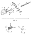
Fig. 6 is an exploded perspective view of a part of the dishwasher ofFigure 3-5 ; -
Fig. 7 is an enlarged perspective view of an element of the dishwasher ofFigure 3-5 ; and -
Fig. 8 is a front view of the element ofFig. 7 . - With reference to
Fig. 1 and 2 , a household dishwasher 10 is schematically represented without front door and withside walls 14,14' partially removed. Dishwasher 10 comprises awashing chamber 12 and arack 16 slidably mounted onrails 18,18'. Rack 16 is designed to hold dishes and other kitchen items to be cleaned, as known in the field.Rails 18,18' are fixed toside walls 14,14' ofwashing chamber 12.Fig. 1 showsrack 16 withinwashing chamber 12, typically corresponding to a state of door closed.Fig. 2 showsrack 16 pulled out fromwashing chamber 12, typically corresponding to a state of door open when loading/unloading the rack. -
Rack 16 is slidably mounted onrails 18,18a by means ofwheels 19 projecting fromsupports 20,20' fixed to the flanks ofrack 16, as better shown inFigures 3-6 . Typically,wheels 19 comprise a pair of upper wheels and a pair of lower wheels, to allow a stable and smooth sliding movement ofrack 16 onrails 18,18'. - According to an aspect of the invention, a pair of
roller chains 22, 22' is connected torails 18,18', to form substantially rigid longitudinal extensions that supportrack 18,18' during sliding movement in and outwashing chamber 12. - Each
roller chain 22, 22' consists of a series ofroller 24, better shown inFigures 6-8 , hinged to each other throughpins 26 with axis X perpendicular to the longitudinal axis ofrails 18, 18'. Each roller is hinged to adjacent rollers by means of two pins, one located in afront portion 23 and the other located in arear portion 25.Front portion 23 is formed with acentral recess 28 suitable to receive therear portion 25 of an adjacent roller, so that apin 26 is inserted into corresponding holes of thefront portion 23 and of the associated rear portion of an adjacent roller to rotatably connect the two adjacent rollers. Rotation of two adjacent rollers, however, is limited to a direction above an horizontal plane in whichrails 18, 18' lay. This is achieved by providingfront portion 23 of eachroller 24 with abottom wall 29, against which the rear portion of an adjacent roller abuts, so that rotation in a direction below an horizontal plane in whichrails 18, 18' lay is prevented. Such structure ofroller 24 prevents a downward bending ofroller chains 22, 22', thereby ensuring thatchains 22, 22' are rigidly aligned torails 18, 18' during sliding ofrack 16 in and outwashing chamber 12. - The
upper portion 30 offront portion 23 of eachroller 24 is bevelled, so that upward bending ofroller chains 22, 22' is possible. - Upward bending of
chains 22, 22' is effected whenrack 16 is pushed into the washing chamber. To this purpose the flanks ofrack 16 are provided withsuitable housing 32, 32' forroller chains 22, 22' in the bent state. As shown inFigure 3-6 ,housings 32, 32' are rigidly connected to supports 20,20' fixed to the flanks ofrack 16.Supports 20, 20' andhousing 32, 32' are preferably made of a single piece, as shown inFig. 6 with reference to support 20 andhousing 32 forchain 22. Such piece includes also shafts such as 34 on whichwheels 19 are mounted. - According to an aspect of the invention,
roller chains 22, 22' bend withinhousings 32, 32' according to a substantially circular path, so that any entanglement or blocking of the motion of the chains caused by a too narrow bend ofrollers 24 is prevented. Also, bending of the chains according to a substantially circular path reduces the space required to store the chain in the bent state. - A bending according to a substantially circular path is achieved by providing a substantially circular groove such as 36 in
housings 32, 32'. As shown inFig. 3 ,groove 36 has a length sufficient to accomodateroller chains 22, 22' for their entire length, corresponding to a state of the rack fully pushed intowashing chamber 12, for instance during washing operation. - Therefore,
roller chains 22, 22' are capable to be in a fully extended position, as shown byFigure 2 and5 , and in a fully bent position, as shown byFigure 1 and3 , and in all intermediate positions in-between, as shown for example inFigure 4 . - In the fully extended position of
Figure 2 and5 ,roller chains 22, 22' are aligned withrails 18, 18', to form substantially rigid longitudinal extensions ofrails 18, 18' that supportrack 16 during sliding in and outwashing chamber 12. The height ofrollers 24 is the same as the height ofrails 18, 18', so that there is no discontinuity in the line of ride ofwheels 19 on the passage from rails to chains, thereby a smooth support towheels 19 is provided. Side skid and downward bending of the chains are prevented by the structure and mutual connection ofrollers 24. Side skid is prevented by the coupling ofrear portions 25 intorecess 28 offront part 23, which allow rotation about X axis only. Bending downwards is prevented bybottom wall 29 offront part 23, as described above. - When
rack 16 is pushed from the fully extended position in the direction ofwashing chamber 12, eachchain 22, 22' is forced to bend by engagingcircular groove 36, as shown inFig. 4 . Bending upwards is eased by the bevelledupper portion 30 ofrollers 24. In the fully bent state ofFig. 3 ,chain 22 occupies almost entirely groove 36, in which it is stored typically when the door of the washing chamber is closed. - The structure of the rack, rails and roller chains assembly according to the invention is such to ensure a reliable and continuous operation.
Roller chains 22, 22' are preferably made of a synthetic resin, for example by moulding each component with a suitable plastic material. This allows to combine the desired mechanical properties with optimum resistance to wet environment and/or chemical corrosion that could be caused by cleaning agents and additives used during operation of the dishwasher. Also,support 20 andhousing 32 can be produced in one piece of suitable plastic material, preferably by injection moulding. Eachrail 18, 18' can be produced in a single piece of suitable plastic material, instead of conventional steel rails, and can be fixed directly to the walls of washingchamber 12, ensuring also a better stability. - It is clear from the description above that other embodiments of the dishwasher according to the invention are possible within the same inventive concept.
Claims (10)
- Dishwasher (10) comprising a washing chamber(12) and a rack (16) slidably mounted on a pair of rails (18,18') in the washing chamber, characterized by comprising a pair of roller chains (22, 22') connected to said rails (18,18') to form substantially rigid longitudinal extensions that support said rack (16) during sliding in and out said washing chamber (12); and further characterized by:- said rollers (24) of said roller chains (22,22') comprising lower portions (29) preventing downward bending of said chains (22,22');- said rack (16) comprising housings (32,32') on the flanks thereof to accommodate said roller chains (22,22') in the bent state.
- Dishwasher according to claim 1, characterized in that said rollers (24) of said roller chains (22,22') comprise bevelled upper portions (30) allowing upward bending of said chains into said housings (32,32').
- Dishwasher according to claim 1, characterized in that said roller chains (22,22') are bent within said housings (32,32') according to a substantially circular path.
- Dishwasher according to claim 3, characterized in that said substantially circular path is defined by a substantially circular groove (36) formed in said housings (32,32'), said groove (36) having a length sufficient to accomodate said roller chains (22,22') entirely.
- Dishwasher according to claim 1, characterized in that said rollers (24) of said roller chains (22,22') are hinged through pins (26) with axis (X) perpendicular to the longitudinal axis of said rails (18,18'), and comprise lower portions (29) limiting rotation to prevent downward bending of the chains, thereby ensuring alignment of said chains (22,22') to said rails (18,18') during sliding of said rack (16) in and out said washing chamber (12).
- Dishwasher according to claim 5, characterized in that said lower portions (29) of said rollers (24) limiting rotation comprise a bottom wall formed in the front portion (23) of each of said roller (24) against which the rear portion (25) of an adjacent roller abuts, so that downward bending of the chain is prevented, thereby ensuring alignment of said chains (22,22') to said rails (18,18') during sliding of said rack (16) in and out said washing chamber (12).
- Dishwasher according to claim 1, characterized in that said housings (32, 32') for said roller chains (22, 22') are rigidly connected to supports (20,20') fixed to the flanks of said rack (16).
- Dishwasher according to claim 7, characterized in that said supports (20, 20') and said housings (32, 32') are made of a single piece.
- Dishwasher according to claim 1, characterized in that said supports (20, 20') and said housings (32, 32') are made of a single piece of plastic material.
- Dishwasher according to claim 9, characterized in that such single piece of plastic material includes also shafts (34) on which wheels (19) are mounted for sliding movement of said rack (16) on said pair of rails (18,18').
Priority Applications (5)
| Application Number | Priority Date | Filing Date | Title |
|---|---|---|---|
| AT07106214T ATE489886T1 (en) | 2007-04-16 | 2007-04-16 | DISHWASHER WITH RAIL-MOUNTED FRAME AND ASSOCIATED ROLLER CHAINS |
| DE602007010902T DE602007010902D1 (en) | 2007-04-16 | 2007-04-16 | Dishwasher with rail mounted rack and associated roller chains |
| PL07106214T PL1982633T3 (en) | 2007-04-16 | 2007-04-16 | Dishwasher with rack mounted on rails and roller chains associated thereto |
| EP07106214A EP1982633B1 (en) | 2007-04-16 | 2007-04-16 | Dishwasher with rack mounted on rails and roller chains associated thereto |
| ES07106214T ES2353554T3 (en) | 2007-04-16 | 2007-04-16 | LAVAPLATOS WITH A FRAME MOUNTED ON RAILS AND ROLLER CHAINS ASSOCIATED WITH THE SAME. |
Applications Claiming Priority (1)
| Application Number | Priority Date | Filing Date | Title |
|---|---|---|---|
| EP07106214A EP1982633B1 (en) | 2007-04-16 | 2007-04-16 | Dishwasher with rack mounted on rails and roller chains associated thereto |
Publications (2)
| Publication Number | Publication Date |
|---|---|
| EP1982633A1 true EP1982633A1 (en) | 2008-10-22 |
| EP1982633B1 EP1982633B1 (en) | 2010-12-01 |
Family
ID=38512485
Family Applications (1)
| Application Number | Title | Priority Date | Filing Date |
|---|---|---|---|
| EP07106214A Not-in-force EP1982633B1 (en) | 2007-04-16 | 2007-04-16 | Dishwasher with rack mounted on rails and roller chains associated thereto |
Country Status (5)
| Country | Link |
|---|---|
| EP (1) | EP1982633B1 (en) |
| AT (1) | ATE489886T1 (en) |
| DE (1) | DE602007010902D1 (en) |
| ES (1) | ES2353554T3 (en) |
| PL (1) | PL1982633T3 (en) |
Cited By (1)
| Publication number | Priority date | Publication date | Assignee | Title |
|---|---|---|---|---|
| US9635995B2 (en) | 2012-10-23 | 2017-05-02 | Whirlpool Corporation | Dishwasher support structures |
Families Citing this family (1)
| Publication number | Priority date | Publication date | Assignee | Title |
|---|---|---|---|---|
| DE102020130186A1 (en) * | 2020-11-16 | 2022-05-19 | Paul Hettich Gmbh & Co. Kg | Household appliance with a storage container |
Citations (6)
| Publication number | Priority date | Publication date | Assignee | Title |
|---|---|---|---|---|
| SU1329767A1 (en) * | 1985-02-19 | 1987-08-15 | С. И. Каиуиникои | Holder for washing,drying and storing utensils |
| JP2001253689A (en) * | 2000-03-14 | 2001-09-18 | Kurimoto Ltd | Link chain winding and feeding device |
| US20040244825A1 (en) * | 2003-06-06 | 2004-12-09 | Ashton Robert H. | Dishwasher with drawer lifting mechanism |
| DE10346861A1 (en) * | 2003-10-09 | 2005-05-04 | Stg Beikirch Industrieelektron | Opener for window or windowed door has chain on a spindle driven by an electric motor and turning across the opening direction |
| EP1552781A2 (en) * | 2004-01-09 | 2005-07-13 | Schock Metallwerk GmbH | Dishwasher with a rack extraction device. |
| DE202006000711U1 (en) * | 2006-01-18 | 2006-04-06 | Anton Schneider Gmbh & Co Kg | Differential extract for drawers or the like. |
-
2007
- 2007-04-16 EP EP07106214A patent/EP1982633B1/en not_active Not-in-force
- 2007-04-16 PL PL07106214T patent/PL1982633T3/en unknown
- 2007-04-16 ES ES07106214T patent/ES2353554T3/en active Active
- 2007-04-16 DE DE602007010902T patent/DE602007010902D1/en active Active
- 2007-04-16 AT AT07106214T patent/ATE489886T1/en not_active IP Right Cessation
Patent Citations (6)
| Publication number | Priority date | Publication date | Assignee | Title |
|---|---|---|---|---|
| SU1329767A1 (en) * | 1985-02-19 | 1987-08-15 | С. И. Каиуиникои | Holder for washing,drying and storing utensils |
| JP2001253689A (en) * | 2000-03-14 | 2001-09-18 | Kurimoto Ltd | Link chain winding and feeding device |
| US20040244825A1 (en) * | 2003-06-06 | 2004-12-09 | Ashton Robert H. | Dishwasher with drawer lifting mechanism |
| DE10346861A1 (en) * | 2003-10-09 | 2005-05-04 | Stg Beikirch Industrieelektron | Opener for window or windowed door has chain on a spindle driven by an electric motor and turning across the opening direction |
| EP1552781A2 (en) * | 2004-01-09 | 2005-07-13 | Schock Metallwerk GmbH | Dishwasher with a rack extraction device. |
| DE202006000711U1 (en) * | 2006-01-18 | 2006-04-06 | Anton Schneider Gmbh & Co Kg | Differential extract for drawers or the like. |
Cited By (2)
| Publication number | Priority date | Publication date | Assignee | Title |
|---|---|---|---|---|
| US9635995B2 (en) | 2012-10-23 | 2017-05-02 | Whirlpool Corporation | Dishwasher support structures |
| US10499790B2 (en) | 2012-10-23 | 2019-12-10 | Whirlpool Corporation | Dishwasher support structures |
Also Published As
| Publication number | Publication date |
|---|---|
| DE602007010902D1 (en) | 2011-01-13 |
| ATE489886T1 (en) | 2010-12-15 |
| EP1982633B1 (en) | 2010-12-01 |
| PL1982633T3 (en) | 2011-05-31 |
| ES2353554T3 (en) | 2011-03-03 |
Similar Documents
| Publication | Publication Date | Title |
|---|---|---|
| EP2818092B1 (en) | Dishwasher | |
| US9579009B2 (en) | Dishwasher with vertically adjustable dish rack | |
| US7410228B2 (en) | Height adjuster mechanism for a dishwasher dish rack | |
| US10022037B2 (en) | Dishwasher with vertically adjustable dish rack | |
| US10548396B1 (en) | Slide device for movable rack | |
| US20150305493A1 (en) | Sliding and pivoting mechanism of a rack of an item of furniture, item of furniture and domestic appliance | |
| CA2686327C (en) | Rack handle member for a dishwasher | |
| CN106413477A (en) | Sliding-pivoting mechanism of a shelf of a piece of furniture or of a domestic appliance, piece of furniture, and domestic appliance | |
| KR102779362B1 (en) | Sliding-pivoting mechanism of a shelf of a piece of furniture or of a household appliance, and piece of furniture or household appliance | |
| CN107249386B (en) | Sliding pivot mechanisms for furniture or appliance shelves, furniture and appliances | |
| US10201230B2 (en) | Drawer rail and home appliance including the same | |
| US8038805B2 (en) | Multi-piece dishrack for a drawer dishwasher | |
| US20070119485A1 (en) | Latching and sealing mechanism for a drawer-type dishwasher | |
| CN104757923A (en) | Dishwasher | |
| EP1982633B1 (en) | Dishwasher with rack mounted on rails and roller chains associated thereto | |
| KR101158796B1 (en) | Roller type slide for household electric appliaces | |
| US9072422B2 (en) | Dishwasher appliance with a detachable door | |
| KR101362316B1 (en) | A attaching/removing structure for refrigerator basket | |
| US10660501B2 (en) | Domestic dishwasher | |
| KR20080044078A (en) | Rack of dishwashers | |
| KR101598842B1 (en) | Slider for drawer | |
| CN114098585B (en) | Wheel stands for dishwashers | |
| EP1464269A1 (en) | Dishwasher basket | |
| KR101561653B1 (en) | slide apparatus for drawer | |
| CN111374618A (en) | Dish washing machine |
Legal Events
| Date | Code | Title | Description |
|---|---|---|---|
| PUAI | Public reference made under article 153(3) epc to a published international application that has entered the european phase |
Free format text: ORIGINAL CODE: 0009012 |
|
| AK | Designated contracting states |
Kind code of ref document: A1 Designated state(s): AT BE BG CH CY CZ DE DK EE ES FI FR GB GR HU IE IS IT LI LT LU LV MC MT NL PL PT RO SE SI SK TR |
|
| AX | Request for extension of the european patent |
Extension state: AL BA HR MK RS |
|
| 17P | Request for examination filed |
Effective date: 20090409 |
|
| AKX | Designation fees paid |
Designated state(s): AT BE BG CH CY CZ DE DK EE ES FI FR GB GR HU IE IS IT LI LT LU LV MC MT NL PL PT RO SE SI SK TR |
|
| GRAP | Despatch of communication of intention to grant a patent |
Free format text: ORIGINAL CODE: EPIDOSNIGR1 |
|
| GRAS | Grant fee paid |
Free format text: ORIGINAL CODE: EPIDOSNIGR3 |
|
| GRAA | (expected) grant |
Free format text: ORIGINAL CODE: 0009210 |
|
| AK | Designated contracting states |
Kind code of ref document: B1 Designated state(s): AT BE BG CH CY CZ DE DK EE ES FI FR GB GR HU IE IS IT LI LT LU LV MC MT NL PL PT RO SE SI SK TR |
|
| REG | Reference to a national code |
Ref country code: GB Ref legal event code: FG4D |
|
| REG | Reference to a national code |
Ref country code: CH Ref legal event code: EP |
|
| REG | Reference to a national code |
Ref country code: IE Ref legal event code: FG4D |
|
| REF | Corresponds to: |
Ref document number: 602007010902 Country of ref document: DE Date of ref document: 20110113 Kind code of ref document: P |
|
| REG | Reference to a national code |
Ref country code: ES Ref legal event code: FG2A Effective date: 20110221 |
|
| REG | Reference to a national code |
Ref country code: NL Ref legal event code: VDEP Effective date: 20101201 |
|
| PG25 | Lapsed in a contracting state [announced via postgrant information from national office to epo] |
Ref country code: LT Free format text: LAPSE BECAUSE OF FAILURE TO SUBMIT A TRANSLATION OF THE DESCRIPTION OR TO PAY THE FEE WITHIN THE PRESCRIBED TIME-LIMIT Effective date: 20101201 |
|
| LTIE | Lt: invalidation of european patent or patent extension |
Effective date: 20101201 |
|
| PG25 | Lapsed in a contracting state [announced via postgrant information from national office to epo] |
Ref country code: SI Free format text: LAPSE BECAUSE OF FAILURE TO SUBMIT A TRANSLATION OF THE DESCRIPTION OR TO PAY THE FEE WITHIN THE PRESCRIBED TIME-LIMIT Effective date: 20101201 Ref country code: LV Free format text: LAPSE BECAUSE OF FAILURE TO SUBMIT A TRANSLATION OF THE DESCRIPTION OR TO PAY THE FEE WITHIN THE PRESCRIBED TIME-LIMIT Effective date: 20101201 Ref country code: FI Free format text: LAPSE BECAUSE OF FAILURE TO SUBMIT A TRANSLATION OF THE DESCRIPTION OR TO PAY THE FEE WITHIN THE PRESCRIBED TIME-LIMIT Effective date: 20101201 Ref country code: SE Free format text: LAPSE BECAUSE OF FAILURE TO SUBMIT A TRANSLATION OF THE DESCRIPTION OR TO PAY THE FEE WITHIN THE PRESCRIBED TIME-LIMIT Effective date: 20101201 Ref country code: AT Free format text: LAPSE BECAUSE OF FAILURE TO SUBMIT A TRANSLATION OF THE DESCRIPTION OR TO PAY THE FEE WITHIN THE PRESCRIBED TIME-LIMIT Effective date: 20101201 Ref country code: BG Free format text: LAPSE BECAUSE OF FAILURE TO SUBMIT A TRANSLATION OF THE DESCRIPTION OR TO PAY THE FEE WITHIN THE PRESCRIBED TIME-LIMIT Effective date: 20110301 Ref country code: NL Free format text: LAPSE BECAUSE OF FAILURE TO SUBMIT A TRANSLATION OF THE DESCRIPTION OR TO PAY THE FEE WITHIN THE PRESCRIBED TIME-LIMIT Effective date: 20101201 Ref country code: CY Free format text: LAPSE BECAUSE OF FAILURE TO SUBMIT A TRANSLATION OF THE DESCRIPTION OR TO PAY THE FEE WITHIN THE PRESCRIBED TIME-LIMIT Effective date: 20101201 |
|
| REG | Reference to a national code |
Ref country code: PL Ref legal event code: T3 |
|
| PG25 | Lapsed in a contracting state [announced via postgrant information from national office to epo] |
Ref country code: GR Free format text: LAPSE BECAUSE OF FAILURE TO SUBMIT A TRANSLATION OF THE DESCRIPTION OR TO PAY THE FEE WITHIN THE PRESCRIBED TIME-LIMIT Effective date: 20110302 |
|
| PG25 | Lapsed in a contracting state [announced via postgrant information from national office to epo] |
Ref country code: PT Free format text: LAPSE BECAUSE OF FAILURE TO SUBMIT A TRANSLATION OF THE DESCRIPTION OR TO PAY THE FEE WITHIN THE PRESCRIBED TIME-LIMIT Effective date: 20110401 Ref country code: BE Free format text: LAPSE BECAUSE OF FAILURE TO SUBMIT A TRANSLATION OF THE DESCRIPTION OR TO PAY THE FEE WITHIN THE PRESCRIBED TIME-LIMIT Effective date: 20101201 Ref country code: IS Free format text: LAPSE BECAUSE OF FAILURE TO SUBMIT A TRANSLATION OF THE DESCRIPTION OR TO PAY THE FEE WITHIN THE PRESCRIBED TIME-LIMIT Effective date: 20110401 Ref country code: EE Free format text: LAPSE BECAUSE OF FAILURE TO SUBMIT A TRANSLATION OF THE DESCRIPTION OR TO PAY THE FEE WITHIN THE PRESCRIBED TIME-LIMIT Effective date: 20101201 Ref country code: CZ Free format text: LAPSE BECAUSE OF FAILURE TO SUBMIT A TRANSLATION OF THE DESCRIPTION OR TO PAY THE FEE WITHIN THE PRESCRIBED TIME-LIMIT Effective date: 20101201 |
|
| PG25 | Lapsed in a contracting state [announced via postgrant information from national office to epo] |
Ref country code: SK Free format text: LAPSE BECAUSE OF FAILURE TO SUBMIT A TRANSLATION OF THE DESCRIPTION OR TO PAY THE FEE WITHIN THE PRESCRIBED TIME-LIMIT Effective date: 20101201 Ref country code: RO Free format text: LAPSE BECAUSE OF FAILURE TO SUBMIT A TRANSLATION OF THE DESCRIPTION OR TO PAY THE FEE WITHIN THE PRESCRIBED TIME-LIMIT Effective date: 20101201 |
|
| PLBE | No opposition filed within time limit |
Free format text: ORIGINAL CODE: 0009261 |
|
| STAA | Information on the status of an ep patent application or granted ep patent |
Free format text: STATUS: NO OPPOSITION FILED WITHIN TIME LIMIT |
|
| PG25 | Lapsed in a contracting state [announced via postgrant information from national office to epo] |
Ref country code: DK Free format text: LAPSE BECAUSE OF FAILURE TO SUBMIT A TRANSLATION OF THE DESCRIPTION OR TO PAY THE FEE WITHIN THE PRESCRIBED TIME-LIMIT Effective date: 20101201 |
|
| 26N | No opposition filed |
Effective date: 20110902 |
|
| PG25 | Lapsed in a contracting state [announced via postgrant information from national office to epo] |
Ref country code: MC Free format text: LAPSE BECAUSE OF NON-PAYMENT OF DUE FEES Effective date: 20110430 |
|
| REG | Reference to a national code |
Ref country code: CH Ref legal event code: PL |
|
| REG | Reference to a national code |
Ref country code: DE Ref legal event code: R097 Ref document number: 602007010902 Country of ref document: DE Effective date: 20110902 |
|
| PG25 | Lapsed in a contracting state [announced via postgrant information from national office to epo] |
Ref country code: MT Free format text: LAPSE BECAUSE OF FAILURE TO SUBMIT A TRANSLATION OF THE DESCRIPTION OR TO PAY THE FEE WITHIN THE PRESCRIBED TIME-LIMIT Effective date: 20101201 |
|
| PG25 | Lapsed in a contracting state [announced via postgrant information from national office to epo] |
Ref country code: LI Free format text: LAPSE BECAUSE OF NON-PAYMENT OF DUE FEES Effective date: 20110430 Ref country code: CH Free format text: LAPSE BECAUSE OF NON-PAYMENT OF DUE FEES Effective date: 20110430 |
|
| REG | Reference to a national code |
Ref country code: IE Ref legal event code: MM4A |
|
| PG25 | Lapsed in a contracting state [announced via postgrant information from national office to epo] |
Ref country code: IE Free format text: LAPSE BECAUSE OF NON-PAYMENT OF DUE FEES Effective date: 20110416 |
|
| PG25 | Lapsed in a contracting state [announced via postgrant information from national office to epo] |
Ref country code: LU Free format text: LAPSE BECAUSE OF NON-PAYMENT OF DUE FEES Effective date: 20110416 |
|
| PG25 | Lapsed in a contracting state [announced via postgrant information from national office to epo] |
Ref country code: TR Free format text: LAPSE BECAUSE OF FAILURE TO SUBMIT A TRANSLATION OF THE DESCRIPTION OR TO PAY THE FEE WITHIN THE PRESCRIBED TIME-LIMIT Effective date: 20101201 |
|
| PG25 | Lapsed in a contracting state [announced via postgrant information from national office to epo] |
Ref country code: HU Free format text: LAPSE BECAUSE OF FAILURE TO SUBMIT A TRANSLATION OF THE DESCRIPTION OR TO PAY THE FEE WITHIN THE PRESCRIBED TIME-LIMIT Effective date: 20101201 |
|
| PGFP | Annual fee paid to national office [announced via postgrant information from national office to epo] |
Ref country code: GB Payment date: 20140416 Year of fee payment: 8 |
|
| PGFP | Annual fee paid to national office [announced via postgrant information from national office to epo] |
Ref country code: FR Payment date: 20140409 Year of fee payment: 8 Ref country code: DE Payment date: 20140430 Year of fee payment: 8 Ref country code: IT Payment date: 20140418 Year of fee payment: 8 |
|
| PGFP | Annual fee paid to national office [announced via postgrant information from national office to epo] |
Ref country code: ES Payment date: 20150310 Year of fee payment: 9 |
|
| PGFP | Annual fee paid to national office [announced via postgrant information from national office to epo] |
Ref country code: PL Payment date: 20150313 Year of fee payment: 9 |
|
| REG | Reference to a national code |
Ref country code: DE Ref legal event code: R119 Ref document number: 602007010902 Country of ref document: DE |
|
| GBPC | Gb: european patent ceased through non-payment of renewal fee |
Effective date: 20150416 |
|
| PG25 | Lapsed in a contracting state [announced via postgrant information from national office to epo] |
Ref country code: GB Free format text: LAPSE BECAUSE OF NON-PAYMENT OF DUE FEES Effective date: 20150416 Ref country code: IT Free format text: LAPSE BECAUSE OF NON-PAYMENT OF DUE FEES Effective date: 20150416 Ref country code: DE Free format text: LAPSE BECAUSE OF NON-PAYMENT OF DUE FEES Effective date: 20151103 |
|
| REG | Reference to a national code |
Ref country code: FR Ref legal event code: ST Effective date: 20151231 |
|
| PG25 | Lapsed in a contracting state [announced via postgrant information from national office to epo] |
Ref country code: FR Free format text: LAPSE BECAUSE OF NON-PAYMENT OF DUE FEES Effective date: 20150430 |
|
| PG25 | Lapsed in a contracting state [announced via postgrant information from national office to epo] |
Ref country code: PL Free format text: LAPSE BECAUSE OF NON-PAYMENT OF DUE FEES Effective date: 20160416 |
|
| PG25 | Lapsed in a contracting state [announced via postgrant information from national office to epo] |
Ref country code: ES Free format text: LAPSE BECAUSE OF NON-PAYMENT OF DUE FEES Effective date: 20160417 |
|
| REG | Reference to a national code |
Ref country code: ES Ref legal event code: FD2A Effective date: 20181205 |