EP1981303A1 - Base station and communication system - Google Patents
Base station and communication system Download PDFInfo
- Publication number
- EP1981303A1 EP1981303A1 EP07713680A EP07713680A EP1981303A1 EP 1981303 A1 EP1981303 A1 EP 1981303A1 EP 07713680 A EP07713680 A EP 07713680A EP 07713680 A EP07713680 A EP 07713680A EP 1981303 A1 EP1981303 A1 EP 1981303A1
- Authority
- EP
- European Patent Office
- Prior art keywords
- section
- rach
- frame
- control information
- terminals
- Prior art date
- Legal status (The legal status is an assumption and is not a legal conclusion. Google has not performed a legal analysis and makes no representation as to the accuracy of the status listed.)
- Withdrawn
Links
Images


Classifications
-
- H—ELECTRICITY
- H04—ELECTRIC COMMUNICATION TECHNIQUE
- H04W—WIRELESS COMMUNICATION NETWORKS
- H04W74/00—Wireless channel access
- H04W74/002—Transmission of channel access control information
- H04W74/006—Transmission of channel access control information in the downlink, i.e. towards the terminal
-
- H—ELECTRICITY
- H04—ELECTRIC COMMUNICATION TECHNIQUE
- H04W—WIRELESS COMMUNICATION NETWORKS
- H04W52/00—Power management, e.g. Transmission Power Control [TPC] or power classes
- H04W52/04—Transmission power control [TPC]
- H04W52/30—Transmission power control [TPC] using constraints in the total amount of available transmission power
- H04W52/36—Transmission power control [TPC] using constraints in the total amount of available transmission power with a discrete range or set of values, e.g. step size, ramping or offsets
-
- H—ELECTRICITY
- H04—ELECTRIC COMMUNICATION TECHNIQUE
- H04W—WIRELESS COMMUNICATION NETWORKS
- H04W52/00—Power management, e.g. Transmission Power Control [TPC] or power classes
- H04W52/04—Transmission power control [TPC]
- H04W52/54—Signalisation aspects of the TPC commands, e.g. frame structure
- H04W52/58—Format of the TPC bits
-
- H—ELECTRICITY
- H04—ELECTRIC COMMUNICATION TECHNIQUE
- H04W—WIRELESS COMMUNICATION NETWORKS
- H04W48/00—Access restriction; Network selection; Access point selection
- H04W48/08—Access restriction or access information delivery, e.g. discovery data delivery
-
- H—ELECTRICITY
- H04—ELECTRIC COMMUNICATION TECHNIQUE
- H04W—WIRELESS COMMUNICATION NETWORKS
- H04W74/00—Wireless channel access
- H04W74/08—Non-scheduled access, e.g. ALOHA
- H04W74/0866—Non-scheduled access, e.g. ALOHA using a dedicated channel for access
-
- H—ELECTRICITY
- H04—ELECTRIC COMMUNICATION TECHNIQUE
- H04W—WIRELESS COMMUNICATION NETWORKS
- H04W88/00—Devices specially adapted for wireless communication networks, e.g. terminals, base stations or access point devices
- H04W88/08—Access point devices
Definitions
- the present invention relates to a communication system having a base station and a plurality of user terminal apparatuses that perform communication with this base station by radio, and a base station.
- the downlink access control method employs central control whereby a base station controls many communication terminal apparatuses.
- a base station uses a "proportional fairness” or “MaxCIR” scheduler, performs access management for each communication terminal apparatus, and performs efficient intra-cell communication terminal apparatus accommodation and control information assignment.
- a problem with the conventional technology is that, when the number of users (the number of communication terminal apparatuses) accommodated by a base station becomes greater than or equal to a predetermined value, the possibility of communication terminal apparatuses performing transmission using the same radio resources increases, and therefore throughput declines due to interference between their signals.
- a base station of the present invention employs a configuration having: a terminal quantity monitoring section that monitors the number of terminals existing in a cell of the local apparatus; a RACH control section that sends control information controlling the RACH frame type corresponding to the number of terminals; and a transmitting section that transmits the control information to the terminals.
- a communication system of the present invention is provided with a base station and a plurality of terminals that perform radio communication with that base station, and employs a configuration wherein the base station has: a terminal quantity monitoring section that monitors the number of terminals existing in a cell of the local apparatus; a RACH control section that sends control information controlling the RACH frame type corresponding to the number of terminals; and a transmitting section that transmits the control information to the terminals; and the terminal has a RACH transmission control section that controls the frame type of a RACH transmit frame according to the control information.
- the present invention enables interference between signals to be prevented and throughput to be improved.
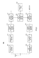
- base station apparatus 100 of this embodiment has RF receiving section 105, demodulation section 110, error correction decoding section 115, error detection section 120, frame processing section 125, user quantity monitoring section 130, handover detection section 135, RACH control section 140, frame type table 145, frame generation section 150, error correction encoding section 155, modulation section 160, and RF transmitting section 165.
- RF receiving section 105 executes predetermined radio processing (such as down-conversion and A/D conversion) on a received signal received via an antenna, and outputs a post-radio-processing received signal to demodulation section 110.
- predetermined radio processing such as down-conversion and A/D conversion
- Demodulation section 110 executes demodulation processing on the post-radio-processing received signal from RF receiving section 105, and outputs the resulting signal to error correction decoding section 115.
- Error correction decoding section 115 executes error correction decoding processing on the post-modulation signal, and outputs the resulting signal to error detection section 120.
- Error detection section 120 detects whether there is an error for the post-error-correction-decoding signal, and outputs an error-free signal to frame processing section 125.
- frame processing section 125 switches to a frame processing method for a frame of a type different from the present one. Then frame processing section 125 performs frame processing on the signal from error detection section 120 using the switched-to frame processing method, and outputs the resulting signal as output data.
- User quantity monitoring section 130 extracts from the receive data from frame processing section 125 terminal identification information of user terminal apparatus 200 described later herein that transmitted that receive data, and uses this terminal identification information to count the number of users (user terminal apparatuses 200) existing in the cell covered by the local apparatus. If user terminal apparatus 200 moves to another cell through handover, there is a report from a host station via a network channel, and on receiving this report, handover detection section 135 outputs a detection signal to user quantity monitoring section 130, and therefore user quantity monitoring section 130 decrements the user count each time this detection signal is received.
- handover detection section 135 outputs a detection signal to user quantity monitoring section 130, and therefore user quantity monitoring section 130 increments the user count each time this detection signal is received.
- User quantitymonitoring section 130 then outputs the current number of users to RACH control section 140.
- RACH control section 140 receives the user count information from user quantity monitoring section 130, searches for a frame type corresponding to the number of users indicated by this user count information in frame type table 145, and acquires that frame type identification information. Then RACH control section 140 outputs the acquired frame type identification information and timing information for changing a transmit frame of user terminal apparatus 200 described later herein to the frame type indicated by that identification information. When a time period corresponding to the above timing information has elapsed since outputting the frame type identification information and the timing information to frame generation section 150, RACH control section 140 outputs the frame type identification information to frame processing section 125.
- Frame type table 145 stores a number of users and a frame type corresponding thereto in mutually associated form.
- frame type table 145 stores numbers of users and frame types corresponding thereto in mutually associated form in such a way that, as the number of users increases, the amount of control information contained in a frame of the frame type corresponding to that number of users decreases. The method of decreasing the amount of control information is described later herein.
- user terminal apparatus 200 described later herein receives frame type identification information output by RACH control section 140, and transmits a frame in a RACH (Random Access CHannel) using the frame type corresponding to that frame type identification information. That is to say, the control information data amount decreases according to the number of users, and user terminal apparatus 200 described later herein can transmit a correspondingly shorter frame. Even if the number of users increases, it is possible to reduce the possibility of frame conflict in the RACH, thereby improving throughput.
- RACH Random Access CHannel
- Frame generation section 150 has user data together with frame type identification information and timing information from RACH control section 140 as input, forms a frame from these items of information, and outputs this frame to error correction encoding section 155.
- Error correction encoding section 155 executes error correction encoding processing on the frame generated by frame generation section 150, and outputs the frame to modulation section 160.
- Modulation section 160 executes modulation processing on the post-error-correction-encoding frame, and outputs the frame to RF transmitting section 165.
- RF transmitting section 165 executes predetermined radio processing (such as D/A conversion and up-conversion) on the post-modulation-processing frame, and transmits the frame via the antenna.
- predetermined radio processing such as D/A conversion and up-conversion
- user terminal apparatus 200 of this embodiment has RF receiving section 205, demodulation section 210, error correction decoding section 215, error detection section 220, RACH transmission control section 225, frame type table 230, frame generation section 235, error correction encoding section 240, modulation section 245, and RF transmitting section 250.
- RF receiving section 205 executes predetermined radio processing (such as down-conversion and A/D conversion) on a received signal received via an antenna, and outputs a post-radio-processing received signal to demodulation section 210.
- predetermined radio processing such as down-conversion and A/D conversion
- Demodulation section 210 executes demodulation processing on the post-radio-processing received signal from RF receiving section 205, and outputs the resulting signal to error correction decoding section 215.
- Error correction decoding section 215 executes error correction decoding processing on the post-modulation signal, and outputs the resulting signal to error detection section 220.
- Error detection section 220 detects whether there is an error for the post-error-correction-decoding signal, and outputs an error-free signal.
- RACH transmission control section 225 has the signal from error detection section 220 as input, and extracts frame type identification information and timing information from this signal. RACH transmission control section 225 then acquires frame type information corresponding to the frame type identification information from frame type table 230. Then, at the timing indicated by the timing information, RACH transmission control section 225 outputs the acquired frame type information to frame generation section 235 and controls the type of frame in the RACH.
- Frame generation section 235 forms a frame from input user data using the frame type corresponding to the latest frame type information received from RACH transmission control section 225. Then frame generation section 235 outputs the formed frame to error correction encoding section 240.
- Error correction encoding section 240 executes error correction encoding processing on the frame from frame generation section 235, and outputs the frame to modulation section 245.
- Modulation section 245 executes modulation processing on the post-error-correction-encoding-processing frame, and outputs the frame to RF transmitting section 250.
- RF transmitting section 250 executes predetermined radio processing (such as D/A conversion and up-conversion) on the post-modulation-processing frame, and transmits the frame via the antenna.
- predetermined radio processing such as D/A conversion and up-conversion
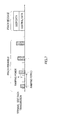
- various kinds of control information are contained in the component parts of a RACH frame.
- base station apparatus 100 is provided with user quantity monitoring section 130 that monitors the number of terminals (users) existing in the cell of the local apparatus, RACH control section 140 that sends out control information (frame type identification information) that controls the RACH frame type, and RF transmitting section 165 that transmits the control information to the terminals.
- user quantity monitoring section 130 that monitors the number of terminals (users) existing in the cell of the local apparatus
- RACH control section 140 that sends out control information (frame type identification information) that controls the RACH frame type
- RF transmitting section 165 that transmits the control information to the terminals.
- RACH control section 140 performs control in such a way that as the number of terminals increases, the amount of control information contained in a frame of the frame type corresponding to that number decreases.
- control information data amount decreases according to the number of users and a correspondingly shorter frame can be transmitted, and even if the number of users increases, it is possible to reduce the possibility of frame conflict, thereby improving overall system throughput.
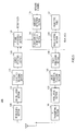
- base station apparatus 300 of Embodiment 2 has RACH control section 310.
- This RACH control section 310 has the same kind of function as RACH control section 140 of Embodiment 1, and also generates preamble control information with contents in accordance with the number of users from user quantity monitoring section 130, and transmits this information at a fixed period to user terminal apparatuses 400 existing in the cell of the local apparatus, via frame generation section 150, error correction encoding section 155, modulation section 160, and RF transmitting section 165.
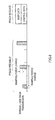
- This preamble control information contains at least one of a PRACH preamble transmission period (repeated until AICH from base station apparatus 300 is received within a fixed period) and/or a ratio of power this time and last time (which may be hereinafter referred to as "ramping power information").
- RACH transmission control section 410 has the same kind of function as RACH transmission control section 225 of Embodiment 1 , and also transmits a PRACH preamble transmitted before transmitting a PRACH message to base station apparatus 300 in accordance with preamble control information from base station apparatus 300.
- preamble control information contains at least one of the PRACH preamble transmission period and/or ramping power information, as described above, when the transmission period is contained in preamble control information, a PRACH preamble is transmitted at that transmission period, and when ramping power information is contained in preamble control information, a PRACH preamble is transmitted while increasing the power in a ratio in accordance with that ramping power information.
- FIG. 7 shows a state in which a PRACH preamble is being transmitted controlled by preamble control information at a certain timing. In contrast, FIG. show a state after a ratio that increases the transmission period and power has been changed by means of preamble control information.
- base station apparatus 300 is provided with user quantity monitoring section 130 that monitors the number of terminals (users) existing in the cell of the local apparatus, RACH control section 320 that sends out control information (frame type identification information) that controls the RACH frame type corresponding to the number of terminals, and RF transmitting section 165 that transmits the control information to the terminals.
- user quantity monitoring section 130 that monitors the number of terminals (users) existing in the cell of the local apparatus
- RACH control section 320 that sends out control information (frame type identification information) that controls the RACH frame type corresponding to the number of terminals
- RF transmitting section 165 that transmits the control information to the terminals.
- RACH control section 310 sends out other control information that controls the RACH preamble transmission period or transmission power ramping according to the number of terminals.
- the present invention has an effect of enabling interference between signals to be prevented and throughput to be improved, and is useful for a base station and communication system.
Landscapes
- Engineering & Computer Science (AREA)
- Computer Networks & Wireless Communication (AREA)
- Signal Processing (AREA)
- Mobile Radio Communication Systems (AREA)
Abstract
Description
- The present invention relates to a communication system having a base station and a plurality of user terminal apparatuses that perform communication with this base station by radio, and a base station.
- In third-generation cellular communications, the downlink access control method employs central control whereby a base station controls many communication terminal apparatuses. A base station uses a "proportional fairness" or "MaxCIR" scheduler, performs access management for each communication terminal apparatus, and performs efficient intra-cell communication terminal apparatus accommodation and control information assignment.
- In an uplink, since a communication terminal apparatus cannot determine at what timing another communication terminal apparatus starts uplink transmission, signaling (connection reservation) by means of a Slotted-ALOHA method is used whereby uplink transmission is started randomly in accordance with frame timing.
- In the Slotted-ALOHA method, when communication terminal apparatuses start transmission using the same radio resource (time, frequency, space, code, etc.), conflict occurs and interference is caused for the respective communications. If uplink information does not reach a base station due to conflict or an environmental cause, a communication terminal apparatus performs random access to the uplink again using a back-off timer (see Patent Document 1).
- Patent Document 1:
Japanese Patent Laid-Open No.3016718 - However, a problem with the conventional technology is that, when the number of users (the number of communication terminal apparatuses) accommodated by a base station becomes greater than or equal to a predetermined value, the possibility of communication terminal apparatuses performing transmission using the same radio resources increases, and therefore throughput declines due to interference between their signals.
- It is an object of the present invention to provide a communication system and base station capable of preventing interference between signals and improving throughput.
- A base station of the present invention employs a configuration having: a terminal quantity monitoring section that monitors the number of terminals existing in a cell of the local apparatus; a RACH control section that sends control information controlling the RACH frame type corresponding to the number of terminals; and a transmitting section that transmits the control information to the terminals.
- A communication system of the present invention is provided with a base station and a plurality of terminals that perform radio communication with that base station, and employs a configuration wherein the base station has: a terminal quantity monitoring section that monitors the number of terminals existing in a cell of the local apparatus; a RACH control section that sends control information controlling the RACH frame type corresponding to the number of terminals; and a transmitting section that transmits the control information to the terminals; and the terminal has a RACH transmission control section that controls the frame type of a RACH transmit frame according to the control information.
- The present invention enables interference between signals to be prevented and throughput to be improved.
-
- FIG. is a block diagram showing the configuration of a base station apparatus according to
Embodiment 1 of the present invention; -
FIG. 2 is a block diagram showing the configuration of a user terminal apparatus according toEmbodiment 1; -
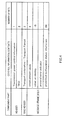
FIG. 3 is a drawing showing the contents of control information contained in a RACH frame; -
FIG. 4 is a drawing showing an example of a RACH frame after the control information amount has been changed; -
FIG.5 is a block diagram showing the configuration of a base station apparatus according toEmbodiment 2 ; -
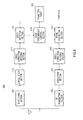
FIG.6 is a block diagram showing the configuration of a user terminal apparatus according toEmbodiment 2 ; -
FIG. 7 is a drawing showing a state in which a PRACH preamble is being transmitted controlled by preamble control information; and -
FIG.8 is a drawing showing a state after a ratio that increases the transmission period and power has been changed by means of preamble control information from the state inFIG. 7 . - Embodiments of the present invention will now be described in detail with reference to the accompanying drawings.
- As shown in
FIG.1 ,base station apparatus 100 of this embodiment hasRF receiving section 105,demodulation section 110, errorcorrection decoding section 115,error detection section 120,frame processing section 125, userquantity monitoring section 130,handover detection section 135,RACH control section 140, frame type table 145,frame generation section 150, errorcorrection encoding section 155,modulation section 160, andRF transmitting section 165. -
RF receiving section 105 executes predetermined radio processing (such as down-conversion and A/D conversion) on a received signal received via an antenna, and outputs a post-radio-processing received signal todemodulation section 110. -
Demodulation section 110 executes demodulation processing on the post-radio-processing received signal fromRF receiving section 105, and outputs the resulting signal to errorcorrection decoding section 115. - Error
correction decoding section 115 executes error correction decoding processing on the post-modulation signal, and outputs the resulting signal toerror detection section 120. -
Error detection section 120 detects whether there is an error for the post-error-correction-decoding signal, and outputs an error-free signal toframe processing section 125. - At the timing at which a received frame type change signal is received,
frame processing section 125 switches to a frame processing method for a frame of a type different from the present one. Thenframe processing section 125 performs frame processing on the signal fromerror detection section 120 using the switched-to frame processing method, and outputs the resulting signal as output data. - User
quantity monitoring section 130 extracts from the receive data fromframe processing section 125 terminal identification information ofuser terminal apparatus 200 described later herein that transmitted that receive data, and uses this terminal identification information to count the number of users (user terminal apparatuses 200) existing in the cell covered by the local apparatus. Ifuser terminal apparatus 200 moves to another cell through handover, there is a report from a host station via a network channel, and on receiving this report,handover detection section 135 outputs a detection signal to userquantity monitoring section 130, and therefore userquantity monitoring section 130 decrements the user count each time this detection signal is received. Ifuser terminal apparatus 200 enters the cell covered by the local apparatus from another cell through handover, there is a report from the host station, and on receiving this report,handover detection section 135 outputs a detection signal to userquantity monitoring section 130, and therefore userquantity monitoring section 130 increments the user count each time this detection signal is received. -
User quantitymonitoring section 130 then outputs the current number of users toRACH control section 140. -
RACH control section 140 receives the user count information from userquantity monitoring section 130, searches for a frame type corresponding to the number of users indicated by this user count information in frame type table 145, and acquires that frame type identification information. ThenRACH control section 140 outputs the acquired frame type identification information and timing information for changing a transmit frame ofuser terminal apparatus 200 described later herein to the frame type indicated by that identification information. When a time period corresponding to the above timing information has elapsed since outputting the frame type identification information and the timing information toframe generation section 150,RACH control section 140 outputs the frame type identification information toframe processing section 125. - Frame type table 145 stores a number of users and a frame type corresponding thereto in mutually associated form.
- Specifically, frame type table 145 stores numbers of users and frame types corresponding thereto in mutually associated form in such a way that, as the number of users increases, the amount of control information contained in a frame of the frame type corresponding to that number of users decreases. The method of decreasing the amount of control information is described later herein.
- Here,
user terminal apparatus 200 described later herein receives frame type identification information output byRACH control section 140, and transmits a frame in a RACH (Random Access CHannel) using the frame type corresponding to that frame type identification information. That is to say, the control information data amount decreases according to the number of users, anduser terminal apparatus 200 described later herein can transmit a correspondingly shorter frame. Even if the number of users increases, it is possible to reduce the possibility of frame conflict in the RACH, thereby improving throughput. -
Frame generation section 150 has user data together with frame type identification information and timing information fromRACH control section 140 as input, forms a frame from these items of information, and outputs this frame to errorcorrection encoding section 155. - Error
correction encoding section 155 executes error correction encoding processing on the frame generated byframe generation section 150, and outputs the frame tomodulation section 160. -
Modulation section 160 executes modulation processing on the post-error-correction-encoding frame, and outputs the frame toRF transmitting section 165. - RF transmitting
section 165 executes predetermined radio processing (such as D/A conversion and up-conversion) on the post-modulation-processing frame, and transmits the frame via the antenna. - As shown in
FIG.2 ,user terminal apparatus 200 of this embodiment hasRF receiving section 205,demodulation section 210, errorcorrection decoding section 215,error detection section 220, RACHtransmission control section 225, frame type table 230,frame generation section 235, errorcorrection encoding section 240,modulation section 245, andRF transmitting section 250. -
RF receiving section 205 executes predetermined radio processing (such as down-conversion and A/D conversion) on a received signal received via an antenna, and outputs a post-radio-processing received signal todemodulation section 210. -
Demodulation section 210 executes demodulation processing on the post-radio-processing received signal fromRF receiving section 205, and outputs the resulting signal to errorcorrection decoding section 215. - Error
correction decoding section 215 executes error correction decoding processing on the post-modulation signal, and outputs the resulting signal toerror detection section 220. -
Error detection section 220 detects whether there is an error for the post-error-correction-decoding signal, and outputs an error-free signal. - RACH
transmission control section 225 has the signal fromerror detection section 220 as input, and extracts frame type identification information and timing information from this signal. RACHtransmission control section 225 then acquires frame type information corresponding to the frame type identification information from frame type table 230. Then, at the timing indicated by the timing information, RACHtransmission control section 225 outputs the acquired frame type information toframe generation section 235 and controls the type of frame in the RACH. -
Frame generation section 235 forms a frame from input user data using the frame type corresponding to the latest frame type information received from RACHtransmission control section 225. Thenframe generation section 235 outputs the formed frame to errorcorrection encoding section 240. - Error
correction encoding section 240 executes error correction encoding processing on the frame fromframe generation section 235, and outputs the frame tomodulation section 245. -
Modulation section 245 executes modulation processing on the post-error-correction-encoding-processing frame, and outputs the frame to RF transmittingsection 250. -
RF transmitting section 250 executes predetermined radio processing (such as D/A conversion and up-conversion) on the post-modulation-processing frame, and transmits the frame via the antenna. - Next, the method of decreasing the amount of control information in a frame will be described.
- As shown in
FIG.3 , various kinds of control information are contained in the component parts of a RACH frame. - The following is a possible pattern for reducing the amount of control information.
- (1) Reduce the number of bits utilized for control of a channel used after the RACH, and more specifically, reduce the number of bits of "TFCI" and "predefined configuration status information".
- (2) Reduce the number of bits of transmission power control information when closed loop power control is performed.
- (3) Reduce the number of bits of control information (specifically, "protocol error indicator") utilized for error processing, reserved bits (specifically, of parts such as "establishment cause", "initial ue identity", "protocol error indicator", "predefined configuration status information", and so forth), and control information that is for the RACH channel but is not necessarily required for communication (specifically, "establishment cause"). An example of control information in which the number of bits has been reduced based on the above pattern is shown in
FIG. 4 . - Thus, according to
Embodiment 1,base station apparatus 100 is provided with userquantity monitoring section 130 that monitors the number of terminals (users) existing in the cell of the local apparatus,RACH control section 140 that sends out control information (frame type identification information) that controls the RACH frame type, andRF transmitting section 165 that transmits the control information to the terminals. - By means of the control information,
RACH control section 140 performs control in such a way that as the number of terminals increases, the amount of control information contained in a frame of the frame type corresponding to that number decreases. - Thus, the control information data amount decreases according to the number of users and a correspondingly shorter frame can be transmitted, and even if the number of users increases, it is possible to reduce the possibility of frame conflict, thereby improving overall system throughput.
- As shown in
FIG.5 ,base station apparatus 300 ofEmbodiment 2 hasRACH control section 310. ThisRACH control section 310 has the same kind of function asRACH control section 140 ofEmbodiment 1, and also generates preamble control information with contents in accordance with the number of users from userquantity monitoring section 130, and transmits this information at a fixed period touser terminal apparatuses 400 existing in the cell of the local apparatus, viaframe generation section 150, errorcorrection encoding section 155,modulation section 160, andRF transmitting section 165. - This preamble control information contains at least one of a PRACH preamble transmission period (repeated until AICH from
base station apparatus 300 is received within a fixed period) and/or a ratio of power this time and last time (which may be hereinafter referred to as "ramping power information"). - As shown in
FiG. 6 ,user terminal apparatus 400 ofEmbodiment 2 has RACHtransmission control section 410. This RACHtransmission control section 410 has the same kind of function as RACHtransmission control section 225 ofEmbodiment 1 , and also transmits a PRACH preamble transmitted before transmitting a PRACH message tobase station apparatus 300 in accordance with preamble control information frombase station apparatus 300. - That is to say, since preamble control information contains at least one of the PRACH preamble transmission period and/or ramping power information, as described above, when the transmission period is contained in preamble control information, a PRACH preamble is transmitted at that transmission period, and when ramping power information is contained in preamble control information, a PRACH preamble is transmitted while increasing the power in a ratio in accordance with that ramping power information.
FIG. 7 shows a state in which a PRACH preamble is being transmitted controlled by preamble control information at a certain timing. In contrast, FIG. show a state after a ratio that increases the transmission period and power has been changed by means of preamble control information. - Thus, according to
Embodiment 2,base station apparatus 300 is provided with userquantity monitoring section 130 that monitors the number of terminals (users) existing in the cell of the local apparatus, RACH control section 320 that sends out control information (frame type identification information) that controls the RACH frame type corresponding to the number of terminals, andRF transmitting section 165 that transmits the control information to the terminals. -
RACH control section 310 sends out other control information that controls the RACH preamble transmission period or transmission power ramping according to the number of terminals. - Thus, by lengthening the preamble transmission period according to the number of terminals, even if the number of users increases it is possible to reduce the possibility of frame (preamble) conflict, thereby preventing a decline in throughput.
- The disclosure of
Japanese Patent Application No. 2006-029055, filed on February 6, 2006 - The present invention has an effect of enabling interference between signals to be prevented and throughput to be improved, and is useful for a base station and communication system.
Claims (4)
- A base station comprising:a terminal quantity monitoring section that monitors a number of terminals existing in a cell of a local apparatus;a RACH control section that sends control information controlling a RACH frame type corresponding to the number of terminals; anda transmitting section that transmits the control information to the terminals.
- The base station according to claim 1, wherein the RACH control section, by means of the control information, performs control in such a way that as the number of terminals increases, an amount of control information contained in a frame of a frame type corresponding to that number decreases.
- The base station according to claim 1, wherein the RACH control section sends out other control information that controls a RACH preamble transmission period or transmission power ramping according to the number of terminals.
- A communication system comprising a base station and a plurality of terminals that perform radio communication with the base station, wherein:the base station has:a terminal quantity monitoring section that monitors a number of terminals existing in a cell of a local apparatus;a RACH control section that sends control information controlling a RACH frame type corresponding to the number of terminals; anda transmitting section that transmits the control information to the terminals, andthe terminal has a RACH transmission control section that controls a frame type of a RACH transmit frame according to the control information.
Applications Claiming Priority (2)
| Application Number | Priority Date | Filing Date | Title |
|---|---|---|---|
| JP2006029055 | 2006-02-06 | ||
| PCT/JP2007/050988 WO2007091420A1 (en) | 2006-02-06 | 2007-01-23 | Base station and communication system |
Publications (2)
| Publication Number | Publication Date |
|---|---|
| EP1981303A1 true EP1981303A1 (en) | 2008-10-15 |
| EP1981303A4 EP1981303A4 (en) | 2012-10-10 |
Family
ID=38345026
Family Applications (1)
| Application Number | Title | Priority Date | Filing Date |
|---|---|---|---|
| EP07713680A Withdrawn EP1981303A4 (en) | 2006-02-06 | 2007-01-23 | BASIC STATION AND COMMUNICATION SYSTEM |
Country Status (4)
| Country | Link |
|---|---|
| US (1) | US20090036153A1 (en) |
| EP (1) | EP1981303A4 (en) |
| JP (1) | JPWO2007091420A1 (en) |
| WO (1) | WO2007091420A1 (en) |
Families Citing this family (8)
| Publication number | Priority date | Publication date | Assignee | Title |
|---|---|---|---|---|
| JP5278642B2 (en) | 2007-10-02 | 2013-09-04 | 日本電気株式会社 | Common channel resource allocation method and apparatus |
| US8400974B2 (en) * | 2009-07-30 | 2013-03-19 | Apple Inc. | Methods and apparatus for providing dynamic information in a wireless information channel |
| JP5106516B2 (en) * | 2009-11-13 | 2012-12-26 | 株式会社エヌ・ティ・ティ・ドコモ | Radio base station and mobile communication method |
| JP5544252B2 (en) * | 2010-09-10 | 2014-07-09 | Kddi株式会社 | Transmission power control apparatus, radio communication system, and transmission power control method |
| JP5234377B2 (en) * | 2011-04-22 | 2013-07-10 | 日本電気株式会社 | Communication method, mobile station and base station in communication system |
| JP5503774B1 (en) | 2013-04-23 | 2014-05-28 | 株式会社Nttドコモ | Wireless tag search method and apparatus |
| US9730196B2 (en) * | 2014-07-29 | 2017-08-08 | Cable Television Laboratories, Inc. | LTE control channel reservation in RF bands with competing communication systems |
| JP2016144055A (en) * | 2015-02-03 | 2016-08-08 | 日本電気株式会社 | COMMUNICATION DEVICE, COMMUNICATION SYSTEM, CONTROL METHOD, AND COMMUNICATION PROGRAM |
Family Cites Families (27)
| Publication number | Priority date | Publication date | Assignee | Title |
|---|---|---|---|---|
| JP2775791B2 (en) * | 1988-12-30 | 1998-07-16 | 日本電気株式会社 | Random access control method for wireless channel |
| JPH089197B2 (en) | 1989-06-15 | 1996-01-31 | 東レ株式会社 | Print laminating method |
| JPH0548610A (en) * | 1991-08-14 | 1993-02-26 | Tokyo Electric Co Ltd | Radio communication system |
| EP2242321B1 (en) * | 1995-09-20 | 2015-07-22 | Ntt Docomo, Inc. | Access method, mobile station and base station for CDMA mobile communication system |
| JPH11289575A (en) * | 1998-04-01 | 1999-10-19 | Nippon Telegr & Teleph Corp <Ntt> | Wireless access control method |
| US6628956B2 (en) * | 1999-03-15 | 2003-09-30 | Telefonaktiebolaget Lm Ericsson (Publ) | Adaptive power control in a radio communications systems |
| JP2001086137A (en) * | 1999-09-17 | 2001-03-30 | Hitachi Kokusai Electric Inc | Wireless communication system |
| US6681256B1 (en) * | 1999-12-21 | 2004-01-20 | Nokia Corporation | Method for dynamically selecting allocation of random access channels in a communication system |
| JP2001251236A (en) * | 2000-03-06 | 2001-09-14 | Matsushita Electric Ind Co Ltd | Communication device |
| JP4441046B2 (en) * | 2000-03-15 | 2010-03-31 | 株式会社日立国際電気 | Wireless communication system |
| CA2313314A1 (en) * | 2000-06-30 | 2001-12-30 | Soma Networks, Inc. | Control channel for a wireless digital subscriber line system |
| DE10056361A1 (en) * | 2000-11-14 | 2002-05-23 | Philips Corp Intellectual Pty | Wireless network for the transmission of parameters for encrypted data transmission |
| JP3735056B2 (en) * | 2001-10-09 | 2006-01-11 | 株式会社日立国際電気 | CDMA radio base station |
| JP2003333661A (en) * | 2002-05-15 | 2003-11-21 | Nec Corp | Mobile communication system, wireless base station device, and random access control method used for them |
| US8320301B2 (en) * | 2002-10-25 | 2012-11-27 | Qualcomm Incorporated | MIMO WLAN system |
| JP4244670B2 (en) * | 2003-03-19 | 2009-03-25 | 日本電気株式会社 | Mobile communication system, radio base station apparatus and operation control method thereof |
| CN1549475A (en) * | 2003-05-12 | 2004-11-24 | 北京三星通信技术研究有限公司 | A Fast Random Access Method for Uplink Dedicated Channel Enhancement in WCDMA System |
| US9473269B2 (en) * | 2003-12-01 | 2016-10-18 | Qualcomm Incorporated | Method and apparatus for providing an efficient control channel structure in a wireless communication system |
| KR101406626B1 (en) * | 2004-06-10 | 2014-06-11 | 고도 가이샤 아이피 브릿지 1 | Radio communication apparatus, communication terminal apparatus, base station apparatus, radio communication system, method for radio communication, and integrated circuit |
| JP2006029055A (en) | 2004-07-20 | 2006-02-02 | Katsuyuki Saito | Free gradient side ditch used for irrigation and draining in common |
| ES2353611T3 (en) * | 2005-01-11 | 2011-03-03 | Ntt Docomo, Inc. | RADIO RESOURCE MANAGEMENT PROCEDURE, RADIO BASE STATION AND RADIO STATION CONTROLLER. |
| KR100895059B1 (en) * | 2005-01-11 | 2009-05-04 | 가부시키가이샤 엔.티.티.도코모 | Transmission rate control method, mobile station and wireless line control station |
| JP2006287489A (en) * | 2005-03-31 | 2006-10-19 | Matsushita Electric Ind Co Ltd | Mobile communication system and downlink initial transmission power control method |
| US9160464B2 (en) * | 2005-09-19 | 2015-10-13 | Nokia Technologies Oy | Operating multi-service receiver in non-interfering manner |
| US20100150056A1 (en) * | 2005-09-30 | 2010-06-17 | Matsushita Electric Industrial Co., Ltd. | Wireless communication mobile station apparatus and rach data transmitting method |
| JP2009055356A (en) * | 2007-08-27 | 2009-03-12 | Ntt Docomo Inc | Base station apparatus, mobile station apparatus and base station control method in mobile communication system |
| ES2424757T5 (en) * | 2007-10-24 | 2018-04-26 | Huawei Technologies Co., Ltd. | Mobile communication system, base station apparatus, mobile station apparatus and mobile communication method |
-
2007
- 2007-01-23 WO PCT/JP2007/050988 patent/WO2007091420A1/en not_active Ceased
- 2007-01-23 US US12/278,381 patent/US20090036153A1/en not_active Abandoned
- 2007-01-23 EP EP07713680A patent/EP1981303A4/en not_active Withdrawn
- 2007-01-23 JP JP2007557777A patent/JPWO2007091420A1/en active Pending
Also Published As
| Publication number | Publication date |
|---|---|
| EP1981303A4 (en) | 2012-10-10 |
| JPWO2007091420A1 (en) | 2009-07-02 |
| US20090036153A1 (en) | 2009-02-05 |
| WO2007091420A1 (en) | 2007-08-16 |
Similar Documents
| Publication | Publication Date | Title |
|---|---|---|
| CN109417777B (en) | Method of selecting subframes excluding subframes related to subframes in which transmission is performed during a sensing period in a wireless communication system in a selection period and terminal using the same | |
| EP3654671B1 (en) | Communication system, mobile station, base station, response decision method, resource configuration decision method, and program | |
| EP1400049B1 (en) | Method for adaptively setting transmission parameters for a random access channel transmission uplink procedure in a wireless communication system | |
| US7848281B2 (en) | Method for selection of an available transmission channel by sending a negative decision value and an additional positive decision value and corresponding base station, mobile terminal and mobile radio network | |
| EP1981303A1 (en) | Base station and communication system | |
| US8285294B2 (en) | Technique for performing a random access procedure over a radio interface | |
| CN106453181B (en) | Information processing method, device and system | |
| EP4044732B1 (en) | Resource allocation method and device | |
| EP3593584B1 (en) | Utilization of unused long-term ul assignments | |
| EP1794950B1 (en) | Scheduling data transmissions in a wireless communications network | |
| EP3372041B1 (en) | Scheduling and accessing of uplink resources | |
| KR20220125299A (en) | Multiple Priority Channel Multiplexing | |
| US10356825B2 (en) | User equipment and method for resource allocation | |
| CN116210324B (en) | Method and apparatus for coordinating uplink grants | |
| CN110581753A (en) | Uplink interference avoidance transmission method and system, base station and user terminal | |
| US20250151029A1 (en) | Methods and apparatuses of resource selection for sidelink communication | |
| TW202402093A (en) | Methods and apparatus for co-channel coexistence | |
| WO2025185686A1 (en) | Transmission method, device, and storage medium | |
| CN118661468A (en) | Method and apparatus for sidelink transmission on unlicensed spectrum |
Legal Events
| Date | Code | Title | Description |
|---|---|---|---|
| PUAI | Public reference made under article 153(3) epc to a published international application that has entered the european phase |
Free format text: ORIGINAL CODE: 0009012 |
|
| 17P | Request for examination filed |
Effective date: 20080804 |
|
| AK | Designated contracting states |
Kind code of ref document: A1 Designated state(s): DE FR GB |
|
| RAP1 | Party data changed (applicant data changed or rights of an application transferred) |
Owner name: PANASONIC CORPORATION |
|
| RBV | Designated contracting states (corrected) |
Designated state(s): DE FR GB |
|
| DAX | Request for extension of the european patent (deleted) | ||
| A4 | Supplementary search report drawn up and despatched |
Effective date: 20120906 |
|
| RIC1 | Information provided on ipc code assigned before grant |
Ipc: H04W 74/00 20090101AFI20120831BHEP |
|
| STAA | Information on the status of an ep patent application or granted ep patent |
Free format text: STATUS: THE APPLICATION IS DEEMED TO BE WITHDRAWN |
|
| 18D | Application deemed to be withdrawn |
Effective date: 20120801 |