EP1981039A1 - Composite superconductor - Google Patents
Composite superconductor Download PDFInfo
- Publication number
- EP1981039A1 EP1981039A1 EP07706753A EP07706753A EP1981039A1 EP 1981039 A1 EP1981039 A1 EP 1981039A1 EP 07706753 A EP07706753 A EP 07706753A EP 07706753 A EP07706753 A EP 07706753A EP 1981039 A1 EP1981039 A1 EP 1981039A1
- Authority
- EP
- European Patent Office
- Prior art keywords
- superconductor
- composite
- groove
- aluminum
- fsw
- Prior art date
- Legal status (The legal status is an assumption and is not a legal conclusion. Google has not performed a legal analysis and makes no representation as to the accuracy of the status listed.)
- Granted
Links
Images


Classifications
-
- H—ELECTRICITY
- H10—SEMICONDUCTOR DEVICES; ELECTRIC SOLID-STATE DEVICES NOT OTHERWISE PROVIDED FOR
- H10N—ELECTRIC SOLID-STATE DEVICES NOT OTHERWISE PROVIDED FOR
- H10N60/00—Superconducting devices
- H10N60/20—Permanent superconducting devices
-
- H—ELECTRICITY
- H10—SEMICONDUCTOR DEVICES; ELECTRIC SOLID-STATE DEVICES NOT OTHERWISE PROVIDED FOR
- H10N—ELECTRIC SOLID-STATE DEVICES NOT OTHERWISE PROVIDED FOR
- H10N60/00—Superconducting devices
- H10N60/01—Manufacture or treatment
- H10N60/0128—Manufacture or treatment of composite superconductor filaments
-
- H—ELECTRICITY
- H01—ELECTRIC ELEMENTS
- H01F—MAGNETS; INDUCTANCES; TRANSFORMERS; SELECTION OF MATERIALS FOR THEIR MAGNETIC PROPERTIES
- H01F6/00—Superconducting magnets; Superconducting coils
- H01F6/06—Coils, e.g. winding, insulating, terminating or casing arrangements therefor
-
- H—ELECTRICITY
- H10—SEMICONDUCTOR DEVICES; ELECTRIC SOLID-STATE DEVICES NOT OTHERWISE PROVIDED FOR
- H10N—ELECTRIC SOLID-STATE DEVICES NOT OTHERWISE PROVIDED FOR
- H10N60/00—Superconducting devices
- H10N60/01—Manufacture or treatment
- H10N60/0184—Manufacture or treatment of devices comprising intermetallic compounds of type A-15, e.g. Nb3Sn
-
- Y—GENERAL TAGGING OF NEW TECHNOLOGICAL DEVELOPMENTS; GENERAL TAGGING OF CROSS-SECTIONAL TECHNOLOGIES SPANNING OVER SEVERAL SECTIONS OF THE IPC; TECHNICAL SUBJECTS COVERED BY FORMER USPC CROSS-REFERENCE ART COLLECTIONS [XRACs] AND DIGESTS
- Y10—TECHNICAL SUBJECTS COVERED BY FORMER USPC
- Y10T—TECHNICAL SUBJECTS COVERED BY FORMER US CLASSIFICATION
- Y10T428/00—Stock material or miscellaneous articles
- Y10T428/31504—Composite [nonstructural laminate]
- Y10T428/31678—Of metal
Definitions
- the present invention relates to a composite superconductor comprising a superconductor and metal material such as aluminum, applicable to not only the conventional alloy superconductor (for example, NbTi or the like) but also compound superconductor which is vulnerable to the mechanical distortion (for example, Nb 3 Sn, Nb 3 Al, Bi-system superconductor, Y-system superconductor, MgB 2 superconductor or the like).
- the aluminum means pure aluminum or pure aluminum alloy defined in the standard.
- the superconductor is cooled to maintain the superconductor properties by means of such forced-flow cooling method or indirect cooling method as being immersed into the cooling medium such as liquid helium, or incorporating a refrigerating system.
- a composite superconductor comprising a superconductor of alloy superconductor material such as NbTi or the like with aluminum is realized, using such properties of the aluminum as high specific heat, high heat transfer, adjustable electrical conductivity, small specific gravity, low radioactivity or the like (refer to the patent document 1 listed hereinafter).
- the composite superconductor is effective, which comprises aluminum and a superconductor of compound superconductor material excellent in such superconductor properties as critical current density, critical magnetic field, and critical temperature, where thermal, mechanical, and electrical contact condition of the superconductor and the aluminum is controlled.
- the compound superconductor material is worked to a predetermined size following drawing and rolling of the raw material including intermediate heat treatments, and then heat-treated to produce a compound superconductor functioning as superconductor.
- produced compound superconductor is brittle to the mechanical distortion. Accordingly, the plastic working thereafter is subjected to a large constrains so as not to deteriorate the superconductor properties.
- the arc welding for example, TIG (tungsten inert gas) welding, or MIG(metallic inert gas) welding
- the arc welding has difficulty in adjustment of the heat amount imparted to the metal member during the welding so that the accuracy of the size in the joint portion is deteriorated, or the superconductor is deformed by thermal strain during the arc welding so that the critical current property is partially deteriorated.
- Object of the present invention is to provide a composite superconductor in which a superconductor such as not only the conventional alloy superconductor (for example, NbTi or the like) but also compound superconductor which is vulnerable to the mechanical distortion (for example, Nb 3 Sn, Nb 3 Al, Bi-system superconductor, Y-system superconductor, MgB 2 superconductor or the like) is covered by the metal member such as aluminum or the like.
- a superconductor such as not only the conventional alloy superconductor (for example, NbTi or the like) but also compound superconductor which is vulnerable to the mechanical distortion (for example, Nb 3 Sn, Nb 3 Al, Bi-system superconductor, Y-system superconductor, MgB 2 superconductor or the like) is covered by the metal member such as aluminum or the like.
- a first aspect of the composite superconductor of the invention is a composite superconductor comprising:
- said member comprises a first member having a groove and a second member fitted to an upper portion of said groove, and said superconductor is placed in a hollow portion formed by combining said first member and said second member.
- said superconductor is placed itself in said hollow portion, or together with a heat transfer member to transfer heat between said superconductor and said heat transfer member, and a ratio of a total cross sectional area of the superconductor and the heat transfer member along a vertical cross section to the cross sectional area of said hollow portion is at least 70 %.
- the filling rate can be appropriately selected according to a pressure applied to the superconductor.
- the cross section of said metal member is substantially circular.
- said superconductor comprising a compound superconductor.
- the compound superconductor there are intermetallic compound superconductor such as Nb 3 Sn, Nb 3 Al, MgB 2 or the like, and oxide superconductor such as Bi-system superconductor, Y-system superconductor or the like.
- the first member and the second member is joined by a friction stir welding (FSW).
- FSW friction stir welding
- the friction stir welding is carried out while a pressure is applied to said superconductor.
- the first member and the second member is joined by a laser beam welding.
- the structure of the composite superconductor which enables to control respective heat, mechanical, electrical contact conditions between the superconductor and the metal member such as aluminum or the like, thus enabling to obtain a composite superconductor having properties corresponding to the intended usage.
- the mechanical distortion applied to the superconductor can be controlled, the superconductor properties including critical current or the like of the compound superconductor can be prevented from being deteriorated.
- the composite superconductor is formed with the compound superconductor which can increase the critical current by applying mechanical distortion to certain degree, the superconductor properties can be improved.
- Fig. 1 is a view illustrating embodiments of the composite superconductor of the invention.
- Fig. 1(a) illustrates a composite superconductor having a rectangular cross section and two welded portions in which two joint portions are respectively welded by FSW.
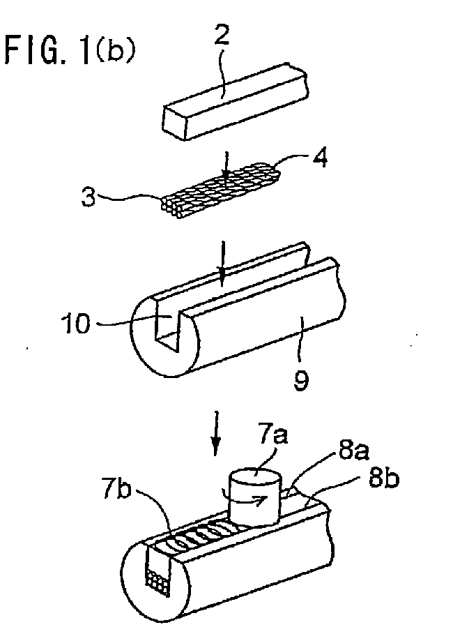
- Fig. 1(b) illustrates a composite superconductor having a circular cross section with a flat portion and two welded portions in which two joint portions are concurrently welded by FSW.
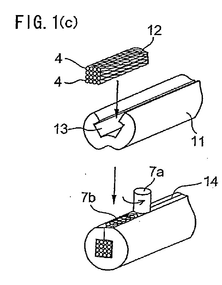
- Fig. 1(c) illustrates a composite superconductor having a circular cross section with a flat portion and one welded portion in which one joint portion is welded by FSW.
- Fig. 1(a) illustrates a composite superconductor having a rectangular cross section and two welded portions in which two joint portions are respectively welded by FSW.
- Fig. 1(b) illustrates a composite superconductor having a circular cross section with a flat portion and two welded portions in which two joint portions are concurrently welded by FSW.
- FIG. 1(d) illustrates a composite superconductor having a circular cross section with a flat portion and two welded portions in which two joint portions are respectively welded by FSW.
- FIG. 2 is a view illustrating embodiments of the superconductor of the invention.
- Fig. 2(a) illustrates round twisted wires comprising 19 pieces of round cross-sectional superconductor wires.
- Fig. 2(b) illustrates a formed superconductor twisted wires in which 8 pieces of round cross-sectional superconductor wires are formed by being twisted and compressed.
- Fig. 2(c) illustrates a formed composite superconductor twisted wires in which the formed superconductor twisted wires are placed between two metal members in sandwiched manner.
- Fig. 1(d) illustrates a composite superconductor having a circular cross section with a flat portion and two welded portions in which two joint portions are respectively welded by FSW.
- Fig. 2 is a view illustrating embodiment
- FIG. 2 (d) illustrates a layered superconductor in which 4 pieces of tape-shaped superconductor wires are layered in vertical direction.
- Fig. 2 (e) illustrates a transposed superconductor in which 9 pieces of the formed superconductor twisted wires are transposed.
- Fig. 2(f) illustrates an impregnated superconductor in which the formed superconductor twisted wires are impregnated in the solder.
- Fig. 2 (g) illustrates another embodiment of the superconductor in which the transposed superconductor with 9 pieces of the formed superconductor twisted wires transposed is wound around by a tape-shaped metal member.
- Fig. 3 illustrates embodiments of a long superconductor of the invention.
- FIG. 3 (a) illustrates a fabricating process of the composite superconductor in which the groove-type metal members are welded in a longitudinal direction by FSW, when the groove-type metal member is shorter than the fitting member and the superconductor in a longitudinal direction.
- Fig. 3(b) illustrates another fabricating process of the composite superconductor in which the groove-type metal member is formed in a prescribed coil shape in advance, then a distortion within a range not to affect superconductivity to the superconductor, then the superconductor is placed in the groove, then the fitting member is fitted to the groove, and then the joint portions are welded by FSW.
- Fig. 1 (a) is a view illustrating a composite superconductor having a rectangular cross section.
- a groove-type aluminum member (a first member) with the rectangular cross section has a groove of two stage portions integrally formed in the aluminum member, which consist of a wide width groove portion 6 and a lower narrow width groove portion 5 narrower than the wide width groove portion 6.
- a formed superconductor twisted wires 4 is placed in the lower narrow width groove portion 5, an aluminum fitting member (a second member) 2 is fitted into the upper wide width groove portion 6, and then, two joint portions 8a, 8b on the upper face thereof are welded by friction stir welding (hereinafter referred to FSW).
- the joint portion is pressed by a rotating tool 7a from the upper side in the drawing, because a pressure is applied in the vertical direction to the wide face of the superconductor (i.e., the formed superconductor twisted wires 4) placed in the aluminum member and a gap within the groove can be reduced.
- a laser beam welding may be applied to the above-described welding.
- the above-described groove of two stage portions i.e., the narrow width groove portion 5 and the wide width groove portion 6 may be the groove of one stage, i.e., one groove portion.
- the metal fitting member (the second member) 2 may be the same material of the groove-type aluminum member (the first member) 1 with the rectangular cross section, or other metal member of a different material.
- Fig. 1(b) is a view illustrating a composite superconductor having a circular cross section with a flat portion.
- the formed superconductor twisted wires 4 is placed on the flat portion in the groove portion 10 of the groove-type aluminum member (a first member) 9 with a circular cross section, a metal fitting member (a second member) 2 is fitted into the groove portion 10, and then, the portion between two joint portions 8a, 8b is pressed by a rotating tool 7a of FSW so that the two joint portions 8a, 8b are welded at once.
- the above-described groove of one stage portion may be the groove of two stages, i.e. , the narrow groove portion 5 and the wide groove portion 6, as illustrated in Fig. 1(a) .
- the metal fitting member (the second member) 2 may be the same material of the groove-type aluminum member (the first member) 9 with the circular cross section, or other metal member of a different material.
- Fig. 1(c) is a view illustrating a composite superconductor having a circular cross section with a flat portion and an opening portion.
- a groove-type aluminum member 11 having a circular cross section with the flat portion and the opening portion has a groove portion 13 beneath the opening portion, in which the layered superconductors 12 are placed. One portion of the aluminum member is cut opened as the opening portion.
- the layered superconductors 12 comprising a plurality of formed superconductor twisted wires 4 (i.e., two formed superconductor twisted wires 4 are layered in the drawing) are placed within the aluminum member through the portion cut opened, the portion cut opened is closed, and then, a joint portion 14 is welded by FSW, thus the layered superconductors 12 are placed within the groove-type aluminum member 11 having the circular cross section.
- There is a method of closing the opening portion in which a bottom portion of the groove-type aluminum member 11 having the circular cross section is deformed within the elastic deformation thereof, the layered superconductors 12 are placed in the groove portion 13 thus opened, and then the aluminum member is closed using elasticity.
- Fig. 1(d) is a view illustrating a composite superconductor having a circular cross section divided into two parts with respective flat portions on which the superconductor is placed within the divided groove-type aluminum members.
- the layered superconductors 12 is placed in a sandwich manner between the divided groove portions 16a, 16b of the divided groove-type aluminum members 15a, 15b having the circular cross section divided into two parts with respective flat portions, and then the divided aluminum members 15a, 15b are closed. Then, the joint portions 17a, 17b of thus closed divided aluminum members are welded by FSW while a pressure is applied to the layered superconductors 12.
- the aluminum member(s) to be combined with the superconductor like the layered superconductors may have the shape in which the superconductor is placed. It is preferable that the aluminum member has the structure in which the superconductor placed within the aluminum member is pressed from outside to the bottom face of the groove portion upon welding.
- Figs. 2(a) to 2(g) Examples of the superconductors to be used for the composite superconductor are shown in Figs. 2(a) to 2(g).
- Fig. 2(a) illustrates superconductor twisted round wires in which a plurality of superconductor round-shaped wires are twisted into a round shape.
- 19 pieces of the superconductor round-shaped wires are twisted into the superconductor twisted round wires 18, however, the number of the superconductor round-shaped wire is not limited to the above.
- Fig. 2(b) illustrates a formed superconductor twisted wires 4 (i.e., formed rectangular twisted wire) in which a plurality of superconductor round-shaped wires 3 are twisted into a rectangular shape.
- Fig. 2(c) illustrates a composite superconductor comprising formed superconductor twisted wires 4 and aluminum plates 19a, 19b as heat transfer member placed on the respective upper and lower faces of the formed superconductor twisted wires 4.
- 8 pieces of superconductor wires are formed into the rectangular-shaped superconductor twisted wires 4, however, the number of the superconductor wire is not limited to the above.
- the aluminum plates 19a, 19b are used as the heat transfer member, however, the material is not limited to aluminum.
- FIG. 2(d) illustrates layered super conductors comprising a plurality of tape-shaped superconductors.
- 4 pieces of tape-shaped superconductors are layered, however, the number of the tape-shaped superconductor is not limited to the above.
- Fig. 2(e) illustrates a transposed superconductor 23 comprising odd-numbered rectangular-shaped twisted formed superconductors which are assembled while being transposed.
- 9 pieces of rectangular-shaped twisted superconductor are transposed, however, odd number of the rectangular-shaped twisted superconductor is not limited to the above.
- Fig. 2 (f) illustrates an embodiment in which superconductor twisted wires 4 are formed into a rectangular shape and impregnated into solder 24 as medium of the heat transfer member.
- Fig. 2 (g) illustrates another embodiment in which aluminum tape is wound around the transposed superconductor 23.
- 9 pieces of rectangular-shaped twisted superconductor 4 are transposed, however, odd number of the rectangular-shaped twisted superconductor is not limited to the above.
- aluminum is used for the tape, however, the material of the tape is not limited to aluminum.
- the superconductor used for the composite superconductor may be selected from the above-described various embodiments.
- a monolithic superconductor wire may also be used for the composite superconductor.
- the superconductor is densely placed within the groove-type aluminum member, and the superconductor is closely contacted with the surrounding aluminum member.
- the superconductor is fully cooled by the enclosing aluminum member.
- the depth d of the groove portion i.e., in Fig. 1(a) , narrow width groove portion 5
- the depth d of the groove portion is set to be smaller than the thickness t of the superconductor (i.e., in Fig.
- the formed superconductor twisted wires 4 thus the superconductor is pressed to the inner bottom face of the groove-type aluminum member when compressed from the upper side thereof so that electrical contact condition, mechanical stability, heat transferability or the like can be excellently maintained.
- the superconductor and the metal member are sufficiently contacted in order to cool the superconductor used for the composite superconductor below the critical temperature by the metal member enclosing the superconductor.
- the superconductor is impregnated into the soldering metal, or the tape such as aluminum tape is wound around the superconductor as the heat transfer member so that the heat transfer from the superconductor to the heat transfer member is enhanced.
- a ratio of the total cross sectional area of the superconductor and the heat transfer member to the hollow portion hereinafter referred to as a "filling rate" in the vertical cross section of the composite superconductor is limited to at least 70%.
- the filling rate is below 70%, it becomes remarkably difficult to control the respective heat, mechanical, and electrical contact conditions between the superconductor and the metal member, thus not preferable.
- the filling rate can be appropriately selected according to the cross sectional design of the members of the composite superconductor as well as a pressure applied to the superconductor.
- Fig. 3 illustrates embodiments of a long composite superconductor.
- Fig. 3(a) illustrates an embodiment of the long composite superconductor in which the length of the groove-type aluminum member 1 having a rectangular cross section is shorter than the formed superconductor twisted wires 4, and two groove-type aluminum members 1 having a rectangular cross section are connected. A plurality of groove-type aluminum members 1 each having the corresponding rectangular cross section are connected without gap.
- the formed superconductor twisted wires 4 is placed in the narrow width groove portion 5 formed in the connected groove-type aluminum members in the same manner as described with reference to Fig. 1(a) .
- the fitting member 2 is fitted into the wide width groove portion 6, and then the joint portions 7a, 7b are respectively welded by FSW.
- Fig. 3 (b) illustrates an embodiment in which the aluminum member is formed to a prescribed coil-shape aluminum member in advance, then, such distortion as those within a range not to affect the properties of the superconductor is applied to the superconductor, then, the superconductor is placed within the groove portion, and then the joint portions are welded.
- the formed superconductor twisted wires with such the distortion as those within a range not to affect the properties of the superconductor applied are placed in the bent groove portion 10' of the formed aluminum member having a circular cross section with flat portion also bent into the prescribed coil shape. Then, the correspondingly bent fitting member 2' to the bent groove portion 10' is fitted therein, and then, the rotating tool is contacted with the portion between two joint portions on the upper surface of the aluminum member, and the joint portions are welded by FSW.
- other embodiments shown in Figs. 1(a), 1(c), and 1(d) can be formed into the respective long composite superconductors in the similar manner.
- Nb 3 Sn superconductor wire 3 not reaction heat treated is manufactured by bronze method, which has a diameter of 0.82mm, a copper ratio of 1, a bronze ratio of 2.3, a diameter of the filament of 3.5mm, and a twist pitch of 25mm, and thus manufactured Nb 3 Sn superconductor wire 3 is plated on the surface thereof by chromium (Cr). 8 pieces of the Cr plated Nb3Sn superconductor wire 3 are twisted and formed to be rectangular twisted wires, and then, subjected to the reaction heat treatment at the temperature of 650 degree centigrade for 96 hours in an argon atmosphere, thus the reaction heat treated Nb 3 Sn superconductor rectangular twisted wires 4 having the width of 3. 4mm, the thickness of 1.57mm, and twist pitch of 35mm is prepared.
- bronze method which has a diameter of 0.82mm, a copper ratio of 1, a bronze ratio of 2.3, a diameter of the filament of 3.5mm, and a twist pitch of 25mm, and thus manufactured N
- Two stage groove comprising a wide width groove portion having a width of 7mm and a depth of 5mm and a narrow width groove portion having a width of 3.5mm and a depth of 1.55mm is formed in the middle of an aluminum alloy (3004) (tempering H112) having a width of 17mm and a thickness of 11mm to prepare the groove-type aluminum member 11 having a rectangular cross section.
- a fitting member to be fitted to the wide width groove portion of the width of 7mm and a depth of 5mm is prepared by an aluminum alloy (3004) (tempering H112).
- the reaction heat treated Nb 3 Sn superconductor rectangular twisted wires 4 is inserted into the narrow width groove portion 5 having a width of 3.5mm and a depth of 1.55mm.
- the fitting member 2 is fitted to the wide width groove portion 6 having a width of 7mm and a depth of 5mm. Then, two joint portions 8b, 8c between the groove-type aluminum member 1 with the rectangular cross section and the fitting member are respectively welded by FSW.
- FSW fastening-sensitive adhesive
- the rotating tool 7a of FSW is pressed to the fitting member 2
- the pressure is indirectly applied to the wide width surface of the reaction heat-treated Nb 3 Sn superconductor rectangular twisted wires 4 in the vertical direction thereof, thus the composite superconductor having the width of 17mm and the thickness of 11mm.
- a steel-made rotating tool is used with the number of rotations of 2500rpm, welding speed of 200mm/min, and under the condition that the tool is moved horizontally.
- Nb 3 Sn superconductor wire 3 not reaction heat treated is manufactured by bronze method, which has a diameter of 0.82mm, a copper ratio of 1, a bronze ratio of 2.3, a diameter of the filament of 3.5mm, and a twist pitch of 25mm, and thus manufactured Nb 3 Sn superconductor wire 3 is plated on the surface thereof by chromium (Cr). 8 pieces of the Cr plated Nb 3 Sn superconductor wire 3 are twisted and formed to be rectangular twisted wires 4 having the width of 3.4mm, the thickness of 1.57mm, and the twist pitch of 35mm.
- the groove having a width of 7.2mm and a depth of 12.5mm is formed in the middle of an aluminum alloy (3004) (tempering H112) having a width of 17mm and a thickness of 17mm to prepare the groove-type aluminum member 11 having a rectangular cross section.
- the reaction heat treated Nb3Sn transposed superconductor 23 is inserted into the groove 10 of the groove type aluminum member 1.
- the fitting member 2 is fitted to the groove 10.
- Example 2 The same reaction heat treated Nb 3 Sn superconductor rectangular twisted wires 4 as described in Example 1 is prepared. Then a composite superconductor having the same outside dimension as that of Example 1 is prepared, using the aluminum member and the above described reaction heat treated Nb 3 Sn superconductor rectangular twisted wires 4 by means of an extrusion coating method (i.e., conform method), thus preparing the comparative example.
- an extrusion coating method i.e., conform method
- the composite superconductors of the examples 1 and 2 of the present invention and the composite superconductor of the comparative example are compared in performance.
- the result thereof is shown in Table 1.
- Table 1 the critical current is not deteriorated in the composite superconductor of the example 1, while the critical current is deteriorated down to less than half in the composite superconductor of the comparative example.
- the composite superconductor of the example 2 the critical current is not deteriorated in almost same manner as that of the example 1, and at least 10kA of current carrying is possible under the condition of 10T external magnetic field.
- the composite superconductor of the example 2 shows the critical current density of the conductor current per total cross sectional area, which is at least 5 times of that of the composite superconductor of the example 1.
- the effect of suppressing deterioration of the critical current properties in the composite superconductor of the present invention can be confirmed.
- the composite superconductor of the invention is effective when it is applied as the large capacity conductor.
- the composite superconductor of the invention is comprehensively excellent than the conventional composite superconductor.
- Example 1 Comparison of the present invention with the conventional art Structure of Nb3Sn superconductor Metal member Critical current density per total cross sectional area of the conductor Strength of aluminum Heat transfer property Comprehensive evaluation
- Example 2 8 pieces of formed twisted wires, 9 pieces of transpos ed conducto rs A3004 ⁇ ⁇ ⁇ ⁇ ⁇
- Comparative example 8 pieces of formed twisted wires A3004 ⁇ ⁇ ⁇ ⁇ ⁇ :good ⁇ :very good ⁇ :deteriorate ⁇ :less deteriorate
- the composite superconductor of the invention can be applied widely to a large scale indirect-cooling superconductor such as thermonuclear generator, large scale SMES or the like, heat transfer-type small and medium scale superconductor such as pulse-type SMES or the like, and the superconductor used for superconductor applied equipment such as a linear motor car, electric transformer, electric generator or the like.
- a large scale indirect-cooling superconductor such as thermonuclear generator, large scale SMES or the like, heat transfer-type small and medium scale superconductor such as pulse-type SMES or the like
- the superconductor used for superconductor applied equipment such as a linear motor car, electric transformer, electric generator or the like.
Landscapes
- Engineering & Computer Science (AREA)
- Manufacturing & Machinery (AREA)
- Superconductors And Manufacturing Methods Therefor (AREA)
- Pressure Welding/Diffusion-Bonding (AREA)
Abstract

Description
- The present invention relates to a composite superconductor comprising a superconductor and metal material such as aluminum, applicable to not only the conventional alloy superconductor (for example, NbTi or the like) but also compound superconductor which is vulnerable to the mechanical distortion (for example, Nb3Sn, Nb3Al, Bi-system superconductor, Y-system superconductor, MgB2 superconductor or the like). Hereinafter the aluminum means pure aluminum or pure aluminum alloy defined in the standard.
- In general, the superconductor is cooled to maintain the superconductor properties by means of such forced-flow cooling method or indirect cooling method as being immersed into the cooling medium such as liquid helium, or incorporating a refrigerating system. More specifically, a composite superconductor comprising a superconductor of alloy superconductor material such as NbTi or the like with aluminum is realized, using such properties of the aluminum as high specific heat, high heat transfer, adjustable electrical conductivity, small specific gravity, low radioactivity or the like (refer to the patent document 1 listed hereinafter).
- However, in order to obtain highly efficient superconductor, it comes to be understood that the composite superconductor is effective, which comprises aluminum and a superconductor of compound superconductor material excellent in such superconductor properties as critical current density, critical magnetic field, and critical temperature, where thermal, mechanical, and electrical contact condition of the superconductor and the aluminum is controlled.
- However, the compound superconductor material is worked to a predetermined size following drawing and rolling of the raw material including intermediate heat treatments, and then heat-treated to produce a compound superconductor functioning as superconductor. Thus produced compound superconductor is brittle to the mechanical distortion. Accordingly, the plastic working thereafter is subjected to a large constrains so as not to deteriorate the superconductor properties. More specifically, when such fabricating method as the extrusion-coating or the wire drawing is applied to the composite superconductor comprising the heat-treated compound superconductor and the metal member, in the same manner to the conventional alloy superconductor, the plastic working is applied thereto such that the critical current property is partially deteriorated, thus the above-described type of the composite superconductor is not realized yet.
- Furthermore, other than the extrusion-coating method and the composite drawing method of the composite superconductor, there is known a method in which a hollow portion is formed by combining two copper members, then the compound superconductor consisting of Nb3Sn is placed in the hollow portion and then the joint portion of the copper members is soldered (refer to the non-patent document 1 listed hereinafter). Since aluminum has high heat transfer and high specific heat, it is necessary to rapidly provide large amount of heat. In addition, aluminum is promptly oxidized so that oxide layer has to be removed before soldering or brazing.
- Accordingly, it is not practical to substitute the above-described copper member by the aluminum member, and then the aluminum members are jointed by soldering or brazing. On the other hand, it is also not practical to carry out the arc welding, since the arc welding (for example, TIG (tungsten inert gas) welding, or MIG(metallic inert gas) welding) has difficulty in adjustment of the heat amount imparted to the metal member during the welding so that the accuracy of the size in the joint portion is deteriorated, or the superconductor is deformed by thermal strain during the arc welding so that the critical current property is partially deteriorated.
- There is known a composite superconductor comprising a compound superconductor of Nb3Al and a metal member of a tubular stainless alloy (refer to the
non-patent document 2 listed hereinafter). According to the above composite superconductor, the supercritical helium is flown through the gap in the metal member so as to coercively cool the superconductor. Thus it is not possible to attain the object of the present invention in which the contact condition between the superconductor and the metal member of aluminum is to be controlled. - Patent document 1: Japanese Patent Application Publication
2000-164053 - Non-patent document 1: Cryogenic engineering 39 vol. 9, 2004, pages 383 to 390, Ando;
- Non-patent document 2: Cryogenic engineering 38 vol. 8, 2003, pages 391 to 398, Koizumi
- Object of the present invention is to provide a composite superconductor in which a superconductor such as not only the conventional alloy superconductor (for example, NbTi or the like) but also compound superconductor which is vulnerable to the mechanical distortion (for example, Nb3Sn, Nb3Al, Bi-system superconductor, Y-system superconductor, MgB2 superconductor or the like) is covered by the metal member such as aluminum or the like.
- A first aspect of the composite superconductor of the invention is a composite superconductor comprising:
- superconductor; and
- a member joined to said superconductor in such manner that said member covers said superconductor, said member comprising metal member at least one of which is aluminum or aluminum alloy.
- In a second aspect of the composite superconductor of the invention, said member comprises a first member having a groove and a second member fitted to an upper portion of said groove, and said superconductor is placed in a hollow portion formed by combining said first member and said second member.
- In a third aspect of the composite superconductor of the invention, said superconductor is placed itself in said hollow portion, or together with a heat transfer member to transfer heat between said superconductor and said heat transfer member, and a ratio of a total cross sectional area of the superconductor and the heat transfer member along a vertical cross section to the cross sectional area of said hollow portion is at least 70 %.
With the filling rate being below 70%, it becomes remarkably difficult to control the respective heat, mechanical, and electrical contact conditions between the superconductor and the metal member, thus not preferable. Incidentally, the filling rate can be appropriately selected according to a pressure applied to the superconductor. - In a fourth aspect of the composite superconductor of the invention, the cross section of said metal member is substantially circular.
- In a fifth aspect of the composite superconductor of the invention, said superconductor comprising a compound superconductor.
As examples of the compound superconductor, there are intermetallic compound superconductor such as Nb3Sn, Nb3Al, MgB2 or the like, and oxide superconductor such as Bi-system superconductor, Y-system superconductor or the like. - In a sixth aspect of the composite superconductor of the invention, the first member and the second member is joined by a friction stir welding (FSW).
- In a seventh aspect of the composite superconductor of the invention, the friction stir welding (FSW) is carried out while a pressure is applied to said superconductor.
- In an eighth aspect of the composite superconductor of the invention, the first member and the second member is joined by a laser beam welding.
- According to present invention, it is possible to find the structure of the composite superconductor which enables to control respective heat, mechanical, electrical contact conditions between the superconductor and the metal member such as aluminum or the like, thus enabling to obtain a composite superconductor having properties corresponding to the intended usage. In particular, since the mechanical distortion applied to the superconductor can be controlled, the superconductor properties including critical current or the like of the compound superconductor can be prevented from being deteriorated. In addition, when the composite superconductor is formed with the compound superconductor which can increase the critical current by applying mechanical distortion to certain degree, the superconductor properties can be improved.
-
Fig. 1 is a view illustrating embodiments of the composite superconductor of the invention.Fig. 1(a) illustrates a composite superconductor having a rectangular cross section and two welded portions in which two joint portions are respectively welded by FSW.Fig. 1(b) illustrates a composite superconductor having a circular cross section with a flat portion and two welded portions in which two joint portions are concurrently welded by FSW.Fig. 1(c) illustrates a composite superconductor having a circular cross section with a flat portion and one welded portion in which one joint portion is welded by FSW.Fig. 1(d) illustrates a composite superconductor having a circular cross section with a flat portion and two welded portions in which two joint portions are respectively welded by FSW.
Fig. 2 is a view illustrating embodiments of the superconductor of the invention.Fig. 2(a) illustrates round twisted wires comprising 19 pieces of round cross-sectional superconductor wires.Fig. 2(b) illustrates a formed superconductor twisted wires in which 8 pieces of round cross-sectional superconductor wires are formed by being twisted and compressed.Fig. 2(c) illustrates a formed composite superconductor twisted wires in which the formed superconductor twisted wires are placed between two metal members in sandwiched manner.Fig. 2 (d) illustrates a layered superconductor in which 4 pieces of tape-shaped superconductor wires are layered in vertical direction.Fig. 2 (e) illustrates a transposed superconductor in which 9 pieces of the formed superconductor twisted wires are transposed.Fig. 2(f) illustrates an impregnated superconductor in which the formed superconductor twisted wires are impregnated in the solder.
Fig. 2 (g) illustrates another embodiment of the superconductor in which the transposed superconductor with 9 pieces of the formed superconductor twisted wires transposed is wound around by a tape-shaped metal member.
Fig. 3 illustrates embodiments of a long superconductor of the invention.Fig. 3 (a) illustrates a fabricating process of the composite superconductor in which the groove-type metal members are welded in a longitudinal direction by FSW, when the groove-type metal member is shorter than the fitting member and the superconductor in a longitudinal direction.Fig. 3(b) illustrates another fabricating process of the composite superconductor in which the groove-type metal member is formed in a prescribed coil shape in advance, then a distortion within a range not to affect superconductivity to the superconductor, then the superconductor is placed in the groove, then the fitting member is fitted to the groove, and then the joint portions are welded by FSW. -
- 1 groove-type aluminum member having a rectangular cross section (first member)
- 2 fitting member (second member)
- 2' bent fitting member
- 3 superconductor wire
- 4 formed superconductor twisted wires (t=thickness)
- 4' bent-formed superconductor twisted wires
- 5 lower narrow width groove portion (d=depth)
- 6 upper wide width groove portion
- 7a rotating tool of FSW
- 7b welded portion by FSW
- 7c welded portion by FSW
- 7d welded portion by FSW
- 8a joint portion
- 8b joint portion
- 9 groove-type aluminum member having a circular cross section with a flat portion
- 9' bent groove-type aluminum member having a circular cross section with a flat portion
- 10 groove
- 10' bent groove
- 11groove-type aluminum member having a circular cross section with a flat portion and opening portion
- 12 layered superconductors
- 13 groove portion below the opening portion
- 14 joint portion
- 15a divided groove-type aluminum member
- 15b divided groove-type aluminum member
- 16a divided groove portion
- 16b divided groove portion
- 17a joint portion
- 17b joint portion
- 18 superconductor twisted round wires
- 19a aluminum plate
- 19b aluminum plate
- 20 formed composite superconductor twisted wires
- 21 tape-shaped superconductor
- 22 layered superconductor
- 23 layered superconductor
- 24 solder
- 25 tape
- 26 joint portion (in the peripheral direction)
- With reference to
Figs. 1 to 3 , embodiments of the superconductor of the present invention will now be described below.
Fig. 1 (a) is a view illustrating a composite superconductor having a rectangular cross section. A groove-type aluminum member (a first member) with the rectangular cross section has a groove of two stage portions integrally formed in the aluminum member, which consist of a widewidth groove portion 6 and a lower narrowwidth groove portion 5 narrower than the widewidth groove portion 6. A formed superconductor twistedwires 4 is placed in the lower narrowwidth groove portion 5, an aluminum fitting member (a second member) 2 is fitted into the upper widewidth groove portion 6, and then, twojoint portions - Upon welding by FSW, it is preferable that the joint portion is pressed by a
rotating tool 7a from the upper side in the drawing, because a pressure is applied in the vertical direction to the wide face of the superconductor (i.e., the formed superconductor twisted wires 4) placed in the aluminum member and a gap within the groove can be reduced. A laser beam welding may be applied to the above-described welding. In this case, when the nearest portion to the welding portion is pressed by a pressing roll, the same effect as FSW ca be obtained. Incidentally, the above-described groove of two stage portions, i.e., the narrowwidth groove portion 5 and the widewidth groove portion 6 may be the groove of one stage, i.e., one groove portion. Furthermore, the metal fitting member (the second member) 2 may be the same material of the groove-type aluminum member (the first member) 1 with the rectangular cross section, or other metal member of a different material. -
Fig. 1(b) is a view illustrating a composite superconductor having a circular cross section with a flat portion. The formed superconductor twistedwires 4 is placed on the flat portion in thegroove portion 10 of the groove-type aluminum member (a first member) 9 with a circular cross section, a metal fitting member (a second member) 2 is fitted into thegroove portion 10, and then, the portion between twojoint portions rotating tool 7a of FSW so that the twojoint portions narrow groove portion 5 and thewide groove portion 6, as illustrated inFig. 1(a) . Furthermore, the metal fitting member (the second member) 2 may be the same material of the groove-type aluminum member (the first member) 9 with the circular cross section, or other metal member of a different material. -
Fig. 1(c) is a view illustrating a composite superconductor having a circular cross section with a flat portion and an opening portion. A groove-type aluminum member 11 having a circular cross section with the flat portion and the opening portion has agroove portion 13 beneath the opening portion, in which the layeredsuperconductors 12 are placed. One portion of the aluminum member is cut opened as the opening portion. Thelayered superconductors 12 comprising a plurality of formed superconductor twisted wires 4 (i.e., two formed superconductor twistedwires 4 are layered in the drawing) are placed within the aluminum member through the portion cut opened, the portion cut opened is closed, and then, ajoint portion 14 is welded by FSW, thus thelayered superconductors 12 are placed within the groove-type aluminum member 11 having the circular cross section. There is a method of closing the opening portion in which a bottom portion of the groove-type aluminum member 11 having the circular cross section is deformed within the elastic deformation thereof, thelayered superconductors 12 are placed in thegroove portion 13 thus opened, and then the aluminum member is closed using elasticity. There is another method of closing the opening portion in which the groove-type aluminum member originally having the opening portion large enough to receive thelayered superconductors 12 within the groove portion, thelayered superconductors 12 are placed in thegroove portion 13 thus opened, and then the aluminum member is mechanically closed by the use of a side roll or a fastening dice. -
Fig. 1(d) is a view illustrating a composite superconductor having a circular cross section divided into two parts with respective flat portions on which the superconductor is placed within the divided groove-type aluminum members. Thelayered superconductors 12 is placed in a sandwich manner between the dividedgroove portions type aluminum members aluminum members joint portions layered superconductors 12.
The aluminum member(s) to be combined with the superconductor like the layered superconductors may have the shape in which the superconductor is placed. It is preferable that the aluminum member has the structure in which the superconductor placed within the aluminum member is pressed from outside to the bottom face of the groove portion upon welding. - Examples of the superconductors to be used for the composite superconductor are shown in
Figs. 2(a) to 2(g). Fig. 2(a) illustrates superconductor twisted round wires in which a plurality of superconductor round-shaped wires are twisted into a round shape. Here, 19 pieces of the superconductor round-shaped wires are twisted into the superconductor twistedround wires 18, however, the number of the superconductor round-shaped wire is not limited to the above.Fig. 2(b) illustrates a formed superconductor twisted wires 4 (i.e., formed rectangular twisted wire) in which a plurality of superconductor round-shapedwires 3 are twisted into a rectangular shape. Here, 8 pieces of the superconductor round-shaped wires are twisted into the formed superconductor twistedwires 4, however, the number of the superconductor round-shaped wire is not limited to the above.Fig. 2(c) illustrates a composite superconductor comprising formed superconductor twistedwires 4 andaluminum plates 19a, 19b as heat transfer member placed on the respective upper and lower faces of the formed superconductor twistedwires 4. Here, 8 pieces of superconductor wires are formed into the rectangular-shaped superconductor twistedwires 4, however, the number of the superconductor wire is not limited to the above. In addition, thealuminum plates 19a, 19b are used as the heat transfer member, however, the material is not limited to aluminum.Fig. 2(d) illustrates layered super conductors comprising a plurality of tape-shaped superconductors. Here, 4 pieces of tape-shaped superconductors are layered, however, the number of the tape-shaped superconductor is not limited to the above.Fig. 2(e) illustrates a transposedsuperconductor 23 comprising odd-numbered rectangular-shaped twisted formed superconductors which are assembled while being transposed. Here, 9 pieces of rectangular-shaped twisted superconductor are transposed, however, odd number of the rectangular-shaped twisted superconductor is not limited to the above.Fig. 2 (f) illustrates an embodiment in which superconductor twistedwires 4 are formed into a rectangular shape and impregnated intosolder 24 as medium of the heat transfer member. Here, 8 pieces of thesuperconductor wires 3 are formed into rectangularly formed superconductor twistedwires 4, however, number of the superconductor wires is not limited to the above. In addition, thesolder 24 is used for the medium of the transfer member, however, the material of the medium is not limited to the solder.
Fig. 2 (g) illustrates another embodiment in which aluminum tape is wound around the transposedsuperconductor 23. Here, 9 pieces of rectangular-shapedtwisted superconductor 4 are transposed, however, odd number of the rectangular-shaped twisted superconductor is not limited to the above. In addition, aluminum is used for the tape, however, the material of the tape is not limited to aluminum. - The superconductor used for the composite superconductor may be selected from the above-described various embodiments. A monolithic superconductor wire may also be used for the composite superconductor. In particular, as an indirectly cooled composite superconductor, it is preferable that the superconductor is densely placed within the groove-type aluminum member, and the superconductor is closely contacted with the surrounding aluminum member. Thus, the superconductor is fully cooled by the enclosing aluminum member. In this regard, the depth d of the groove portion (i.e., in
Fig. 1(a) , narrow width groove portion 5) is set to be smaller than the thickness t of the superconductor (i.e., inFig. 1(a) , the formed superconductor twisted wires 4), thus the superconductor is pressed to the inner bottom face of the groove-type aluminum member when compressed from the upper side thereof so that electrical contact condition, mechanical stability, heat transferability or the like can be excellently maintained. - It is necessary that the superconductor and the metal member are sufficiently contacted in order to cool the superconductor used for the composite superconductor below the critical temperature by the metal member enclosing the superconductor. For this purpose, the superconductor is impregnated into the soldering metal, or the tape such as aluminum tape is wound around the superconductor as the heat transfer member so that the heat transfer from the superconductor to the heat transfer member is enhanced. Here, a ratio of the total cross sectional area of the superconductor and the heat transfer member to the hollow portion (hereinafter referred to as a "filling rate") in the vertical cross section of the composite superconductor is limited to at least 70%. With the filling rate being below 70%, it becomes remarkably difficult to control the respective heat, mechanical, and electrical contact conditions between the superconductor and the metal member, thus not preferable. Incidentally, the filling rate can be appropriately selected according to the cross sectional design of the members of the composite superconductor as well as a pressure applied to the superconductor.
-
Fig. 3 illustrates embodiments of a long composite superconductor.Fig. 3(a) illustrates an embodiment of the long composite superconductor in which the length of the groove-type aluminum member 1 having a rectangular cross section is shorter than the formed superconductor twistedwires 4, and two groove-type aluminum members 1 having a rectangular cross section are connected. A plurality of groove-type aluminum members 1 each having the corresponding rectangular cross section are connected without gap. The formed superconductor twistedwires 4 is placed in the narrowwidth groove portion 5 formed in the connected groove-type aluminum members in the same manner as described with reference toFig. 1(a) . Thefitting member 2 is fitted into the widewidth groove portion 6, and then thejoint portions peripheral direction 26 may be welded by FSW, or the laser beam welding. Other welding methods can be applied thereto. The embodiments described with reference toFigs. 1(b) to 1(d) can be connected in the similar manner as the embodiment described with reference toFig. 1(a) .Fig. 3 (b) illustrates an embodiment in which the aluminum member is formed to a prescribed coil-shape aluminum member in advance, then, such distortion as those within a range not to affect the properties of the superconductor is applied to the superconductor, then, the superconductor is placed within the groove portion, and then the joint portions are welded. More specifically, the formed superconductor twisted wires with such the distortion as those within a range not to affect the properties of the superconductor applied, are placed in the bent groove portion 10' of the formed aluminum member having a circular cross section with flat portion also bent into the prescribed coil shape. Then, the correspondingly bent fitting member 2' to the bent groove portion 10' is fitted therein, and then, the rotating tool is contacted with the portion between two joint portions on the upper surface of the aluminum member, and the joint portions are welded by FSW. In addition to the embodiment described with reference toFig. 1(b) , other embodiments shown inFigs. 1(a), 1(c), and 1(d) can be formed into the respective long composite superconductors in the similar manner. - Nb3
Sn superconductor wire 3 not reaction heat treated is manufactured by bronze method, which has a diameter of 0.82mm, a copper ratio of 1, a bronze ratio of 2.3, a diameter of the filament of 3.5mm, and a twist pitch of 25mm, and thus manufactured Nb3Sn superconductor wire 3 is plated on the surface thereof by chromium (Cr). 8 pieces of the Cr platedNb3Sn superconductor wire 3 are twisted and formed to be rectangular twisted wires, and then, subjected to the reaction heat treatment at the temperature of 650 degree centigrade for 96 hours in an argon atmosphere, thus the reaction heat treated Nb3Sn superconductor rectangulartwisted wires 4 having the width of 3. 4mm, the thickness of 1.57mm, and twist pitch of 35mm is prepared. - Two stage groove comprising a wide width groove portion having a width of 7mm and a depth of 5mm and a narrow width groove portion having a width of 3.5mm and a depth of 1.55mm is formed in the middle of an aluminum alloy (3004) (tempering H112) having a width of 17mm and a thickness of 11mm to prepare the groove-
type aluminum member 11 having a rectangular cross section. In addition, a fitting member to be fitted to the wide width groove portion of the width of 7mm and a depth of 5mm is prepared by an aluminum alloy (3004) (tempering H112). The reaction heat treated Nb3Sn superconductor rectangulartwisted wires 4 is inserted into the narrowwidth groove portion 5 having a width of 3.5mm and a depth of 1.55mm. Thefitting member 2 is fitted to the widewidth groove portion 6 having a width of 7mm and a depth of 5mm. Then, twojoint portions 8b, 8c between the groove-type aluminum member 1 with the rectangular cross section and the fitting member are respectively welded by FSW. Upon welding, when therotating tool 7a of FSW is pressed to thefitting member 2, the pressure is indirectly applied to the wide width surface of the reaction heat-treated Nb3Sn superconductor rectangulartwisted wires 4 in the vertical direction thereof, thus the composite superconductor having the width of 17mm and the thickness of 11mm. Incidentally, upon welding, a steel-made rotating tool is used with the number of rotations of 2500rpm, welding speed of 200mm/min, and under the condition that the tool is moved horizontally. - Nb3
Sn superconductor wire 3 not reaction heat treated is manufactured by bronze method, which has a diameter of 0.82mm, a copper ratio of 1, a bronze ratio of 2.3, a diameter of the filament of 3.5mm, and a twist pitch of 25mm, and thus manufactured Nb3Sn superconductor wire 3 is plated on the surface thereof by chromium (Cr). 8 pieces of the Cr plated Nb3Sn superconductor wire 3 are twisted and formed to be rectangulartwisted wires 4 having the width of 3.4mm, the thickness of 1.57mm, and the twist pitch of 35mm. 9 pieces of thus formed superconductor rectangulartwisted wires 4 are transposed with the pitch of 55mm to form the transposed superconductor having the width of 7.0mm and the thickness of 8.0mm, and then, the transposed superconductor is subjected to the reaction heat treatment at the temperature of 650 degree centigrade for 96 hours in an argon atmosphere, thus the reaction heat treated Nb3Sn transposed superconductor is prepared. - The groove having a width of 7.2mm and a depth of 12.5mm is formed in the middle of an aluminum alloy (3004) (tempering H112) having a width of 17mm and a thickness of 17mm to prepare the groove-
type aluminum member 11 having a rectangular cross section. In addition, afitting member 2 having the width of 7.1mm and the thickness of 4.5mm to be fitted to the groove, in which the reaction heat treated Nb3Sn transposedsuperconductor 23 is inserted, is prepared by an aluminum alloy (3004)(tempering H112). The reaction heat treated Nb3Sn transposedsuperconductor 23 is inserted into thegroove 10 of the groove type aluminum member 1. Thefitting member 2 is fitted to thegroove 10. Then, twojoint portions fitting member 2 are respectively welded by FSW. Upon welding, when therotating tool 7a of FSW is pressed to thefitting member 2, the pressure is indirectly applied to the wide width surface of the Nb3Sn superconductor rectangulartwisted wires 4 in the reaction heat-treated Nb3Sn transposedsuperconductor 23 in the vertical direction thereof, thus the composite superconductor having the width of 17mm and the thickness of 17mm. Incidentally, upon welding, a steel-made rotating tool in the same manner as described in Example 1 is used with the number of rotations of 2500rpm, welding speed of 200mm/min, and under the condition that the tool is moved horizontally. - The same reaction heat treated Nb3Sn superconductor rectangular
twisted wires 4 as described in Example 1 is prepared. Then a composite superconductor having the same outside dimension as that of Example 1 is prepared, using the aluminum member and the above described reaction heat treated Nb3Sn superconductor rectangulartwisted wires 4 by means of an extrusion coating method (i.e., conform method), thus preparing the comparative example. - The composite superconductors of the examples 1 and 2 of the present invention and the composite superconductor of the comparative example are compared in performance. The result thereof is shown in Table 1. As is shown in Table 1, the critical current is not deteriorated in the composite superconductor of the example 1, while the critical current is deteriorated down to less than half in the composite superconductor of the comparative example. In the composite superconductor of the example 2, the critical current is not deteriorated in almost same manner as that of the example 1, and at least 10kA of current carrying is possible under the condition of 10T external magnetic field. In addition, the composite superconductor of the example 2 shows the critical current density of the conductor current per total cross sectional area, which is at least 5 times of that of the composite superconductor of the example 1.
- This means that even if the size of the superconductor becomes large, the outside dimension of the aluminum member remains the same, thus the ratio of the metal member to the overall size of the composite superconductor can be relatively small. Furthermore, the strength of the aluminum members in the composite superconductor of the examples 1 and 2 remains unchanged, while the strength of the aluminum member in the composite superconductor of the comparative example is deteriorated due to the heat generated during the extrusion. The heat transfer property in the composite superconductors of the examples 1 and 2 fully satisfy the practical level, even though the composite superconductor of the comparative example is high due to the metallic binding of the superconductor and the aluminum member.
As is clear from the foregoing, the effect of suppressing deterioration of the critical current properties in the composite superconductor of the present invention can be confirmed. In addition, it is clear that the composite superconductor of the invention is effective when it is applied as the large capacity conductor. Thus, the composite superconductor of the invention is comprehensively excellent than the conventional composite superconductor.[Table 1] Comparison of the present invention with the conventional art Structure of Nb3Sn superconductor Metal member Critical current density per total cross sectional area of the conductor Strength of aluminum Heat transfer property Comprehensive evaluation Example 1 8 pieces of formed twisted wires A3004 ○ ○ ○ ○ Example 2 8 pieces of formed twisted wires, 9 pieces of transpos ed conducto rs A3004 ⊚ ○ ○ ⊚ Comparative example 8 pieces of formed twisted wires A3004 × △ ⊚ × ○:good ⊚:very good ×:deteriorate △:less deteriorate - The composite superconductor of the invention can be applied widely to a large scale indirect-cooling superconductor such as thermonuclear generator, large scale SMES or the like, heat transfer-type small and medium scale superconductor such as pulse-type SMES or the like, and the superconductor used for superconductor applied equipment such as a linear motor car, electric transformer, electric generator or the like.
Claims (8)
- A composite superconductor comprising:superconductor; andat least one member joined to said superconductor in such manner that said member covers said superconductor, said member comprising metal member at least one of which is aluminum or aluminum alloy.
- The composite superconductor according to claim 1, wherein said member comprises a first member having a groove and a second member fitted to an upper portion of said groove, and said superconductor is placed in a hollow portion formed by combining said first member and said second member.
- The composite superconductor according to claim 2, wherein said superconductor is placed itself or together with a heat transfer member to transfer heat between said superconductor and said member in said hollow portion, and a ratio of a total cross sectional area of the superconductor and the heat transfer member to the cross sectional area of said hollow portion is at least 70 %.
- The composite superconductor according to claim 1, wherein the cross section of said member is substantially circular.
- The composite superconductor according to any one of claims 1 to 4, wherein said superconductor comprising a compound superconductor material.
- The composite superconductor according to any one of claims 1 to 5, wherein the first member and the second member is joined by a friction stir welding (FSW).
- The composite superconductor according to claim 6, wherein the friction stir welding (FSW) is carried out while a pressure is applied to said superconductor.
- The composite superconductor according to any one of claims 1 to 5, wherein the first member and the second member is joined by a laser beam welding.
Applications Claiming Priority (2)
| Application Number | Priority Date | Filing Date | Title |
|---|---|---|---|
| JP2006007993 | 2006-01-16 | ||
| PCT/JP2007/050419 WO2007081005A1 (en) | 2006-01-16 | 2007-01-15 | Composite superconductor |
Publications (3)
| Publication Number | Publication Date |
|---|---|
| EP1981039A1 true EP1981039A1 (en) | 2008-10-15 |
| EP1981039A4 EP1981039A4 (en) | 2012-08-01 |
| EP1981039B1 EP1981039B1 (en) | 2014-04-30 |
Family
ID=38256406
Family Applications (1)
| Application Number | Title | Priority Date | Filing Date |
|---|---|---|---|
| EP07706753.6A Active EP1981039B1 (en) | 2006-01-16 | 2007-01-15 | Method for producing a composite superconductor |
Country Status (3)
| Country | Link |
|---|---|
| US (1) | US9105795B2 (en) |
| EP (1) | EP1981039B1 (en) |
| WO (1) | WO2007081005A1 (en) |
Cited By (2)
| Publication number | Priority date | Publication date | Assignee | Title |
|---|---|---|---|---|
| CN104883011A (en) * | 2014-02-27 | 2015-09-02 | 株式会社东芝 | Method Of Manufacturing Rotor Coil And Rotary Electrical Machine |
| CN118609905A (en) * | 2024-08-08 | 2024-09-06 | 西安聚能超导线材科技有限公司 | A NbTi superconducting wire and a method for preparing the same |
Families Citing this family (6)
| Publication number | Priority date | Publication date | Assignee | Title |
|---|---|---|---|---|
| US7762447B2 (en) | 2008-03-20 | 2010-07-27 | Ut-Battelle, Llc | Multiple pass and multiple layer friction stir welding and material enhancement processes |
| JP2012218009A (en) * | 2011-04-05 | 2012-11-12 | Suzuki Motor Corp | Method of bonding dissimilar metal materials and bonded body of dissimilar metal materials |
| JP6090933B2 (en) | 2011-09-06 | 2017-03-08 | 古河電気工業株式会社 | Composite superconductor and method of manufacturing composite superconductor |
| DE102012218250A1 (en) * | 2012-10-05 | 2014-04-10 | Bruker Eas Gmbh | Method for producing a superconducting wire, in particular using lead-free solders |
| FI20145755A7 (en) * | 2014-09-01 | 2016-03-02 | Luvata Espoo Oy | A metal assembly comprising a superconductor |
| CN113903528A (en) * | 2021-08-26 | 2022-01-07 | 合肥聚能电物理高技术开发有限公司 | CICC conductor forming tool and forming process thereof |
Family Cites Families (16)
| Publication number | Priority date | Publication date | Assignee | Title |
|---|---|---|---|---|
| CH489924A (en) * | 1968-04-06 | 1970-04-30 | Siemens Ag | Process for the production of a conductor composed of at least one superconductor and normally conductive metals |
| CH592946A5 (en) * | 1975-12-15 | 1977-11-15 | Bbc Brown Boveri & Cie | |
| IT1160239B (en) * | 1983-12-23 | 1987-03-04 | Metalli Ind Spa | PROCEDURE FOR THE PRODUCTION OF SUPERCONDUCTIVE CONDUCTORS ENTIRELY BRAZED TO A STABILIZATION SHEATH AND CONDUCTORS OBTAINED BY SUCH PROCEDURE |
| US5620798A (en) * | 1995-05-17 | 1997-04-15 | The Babcock & Wilcox Company | Aluminum stabilized superconductor supported by aluminum alloy sheath |
| JP3265939B2 (en) * | 1995-08-31 | 2002-03-18 | 日立電線株式会社 | Manufacturing method of composite superconducting conductor |
| JPH0973824A (en) * | 1995-09-04 | 1997-03-18 | Hitachi Cable Ltd | Method for manufacturing composite superconducting conductor |
| JPH0973821A (en) * | 1995-09-06 | 1997-03-18 | Hitachi Cable Ltd | Aluminum stabilized composite superconducting conductor |
| JP3472452B2 (en) | 1997-09-11 | 2003-12-02 | 日立電線株式会社 | Aluminum stabilized superconducting conductor |
| JPH10321060A (en) | 1997-05-23 | 1998-12-04 | Furukawa Electric Co Ltd:The | Aluminum stabilized superconducting wire |
| WO2000017890A1 (en) * | 1998-09-22 | 2000-03-30 | The Furukawa Electric Co., Ltd. | Method for producing aluminum-stabilized super conductive wire |
| JP3464423B2 (en) * | 1998-09-22 | 2003-11-10 | 古河電気工業株式会社 | Manufacturing method of aluminum stabilized superconducting wire |
| JP4213290B2 (en) | 1999-04-12 | 2009-01-21 | 株式会社神戸製鋼所 | Method for producing stabilized composite superconducting wire |
| JP2001283653A (en) * | 2000-01-25 | 2001-10-12 | Hitachi Cable Ltd | Aluminum composite superconducting wire |
| JP2001267120A (en) * | 2000-03-22 | 2001-09-28 | Hitachi Ltd | Superconducting coil joining method and superconducting magnet |
| US6687975B2 (en) * | 2001-03-09 | 2004-02-10 | Hyper Tech Research Inc. | Method for manufacturing MgB2 intermetallic superconductor wires |
| CN100406190C (en) * | 2001-11-02 | 2008-07-30 | 波音公司 | Apparatus and method for forming a weld joint having a distribution of residual compressive stress |
-
2007
- 2007-01-15 EP EP07706753.6A patent/EP1981039B1/en active Active
- 2007-01-15 WO PCT/JP2007/050419 patent/WO2007081005A1/en not_active Ceased
-
2008
- 2008-07-15 US US12/160,964 patent/US9105795B2/en active Active
Cited By (4)
| Publication number | Priority date | Publication date | Assignee | Title |
|---|---|---|---|---|
| CN104883011A (en) * | 2014-02-27 | 2015-09-02 | 株式会社东芝 | Method Of Manufacturing Rotor Coil And Rotary Electrical Machine |
| EP2913908A3 (en) * | 2014-02-27 | 2016-07-27 | Kabushiki Kaisha Toshiba | Method of manufacturing a rotor coil and corresponding rotary electrical machine |
| CN104883011B (en) * | 2014-02-27 | 2017-09-19 | 株式会社东芝 | The manufacture method and electric rotating machine of rotor coil |
| CN118609905A (en) * | 2024-08-08 | 2024-09-06 | 西安聚能超导线材科技有限公司 | A NbTi superconducting wire and a method for preparing the same |
Also Published As
| Publication number | Publication date |
|---|---|
| US9105795B2 (en) | 2015-08-11 |
| EP1981039A4 (en) | 2012-08-01 |
| EP1981039B1 (en) | 2014-04-30 |
| WO2007081005A1 (en) | 2007-07-19 |
| US20100222222A1 (en) | 2010-09-02 |
Similar Documents
| Publication | Publication Date | Title |
|---|---|---|
| US9105795B2 (en) | Composite superconductor | |
| EP2741302B1 (en) | Composite superconductor, and method for producing composite superconductor | |
| US5801124A (en) | Laminated superconducting ceramic composite conductors | |
| CN101356660B (en) | Wire-in-channel superconductor and method of manufacturing the same | |
| US4161062A (en) | Method for producing hollow superconducting cables | |
| JP4936525B2 (en) | Composite superconductor | |
| JP6101490B2 (en) | Oxide superconducting wire connection structure and superconducting equipment | |
| EP0613192B1 (en) | Wire for NB3X superconducting wire | |
| JP2015028912A (en) | Superconducting wire and superconducting coil using the same | |
| JP5693798B2 (en) | Oxide superconducting wire | |
| US20040226163A1 (en) | Increasing the copper to superconductor ratio of a superconductor wire by cladding with copper-based strip | |
| JP2009117202A (en) | Superconducting tape, superconducting tape manufacturing method, coil, and magnet | |
| KR101417999B1 (en) | Manufacturing method of copper clad aluminum wire | |
| JP4792713B2 (en) | Lead wire, manufacturing method thereof, and solar cell assembly | |
| US20240274327A1 (en) | Precursor wire for compound superconducting wire, compound superconducting wire, and rewinding method for compound superconducting wire | |
| JP4791346B2 (en) | Nb3Sn superconducting wire, precursor therefor, and Nb composite single core wire for precursor | |
| GB1569983A (en) | Super conductor | |
| JP2004342561A (en) | Nb3sn superconductive wire | |
| JP3757141B2 (en) | Manufacturing method of Nb (3) Sn superconducting wire | |
| JP2016115574A (en) | Superconducting wire rod and superconducting coil using it | |
| JP2868966B2 (en) | Superconducting wire manufacturing method | |
| JP5775810B2 (en) | Manufacturing method of oxide superconducting wire | |
| JP5697162B2 (en) | Current lead | |
| JPH05880B2 (en) | ||
| JP4723345B2 (en) | Method for producing Nb3Sn superconducting wire and precursor therefor |
Legal Events
| Date | Code | Title | Description |
|---|---|---|---|
| PUAI | Public reference made under article 153(3) epc to a published international application that has entered the european phase |
Free format text: ORIGINAL CODE: 0009012 |
|
| 17P | Request for examination filed |
Effective date: 20080808 |
|
| AK | Designated contracting states |
Kind code of ref document: A1 Designated state(s): DE GB IT |
|
| RIN1 | Information on inventor provided before grant (corrected) |
Inventor name: USHIYAMA, TOSHIO Inventor name: MITO, TOSHIYUKI Inventor name: TAKAHATA, KAZUYA Inventor name: TSUBOUCHI, HIROKAZU Inventor name: SUGIMOTO, MASAHIROC/O THE FURUKAWA ELECTRIC CO., L Inventor name: OKADA, TOSHIYA |
|
| RBV | Designated contracting states (corrected) |
Designated state(s): DE GB IT |
|
| A4 | Supplementary search report drawn up and despatched |
Effective date: 20120628 |
|
| RIC1 | Information provided on ipc code assigned before grant |
Ipc: H01F 6/06 20060101ALI20120622BHEP Ipc: H01B 12/10 20060101ALI20120622BHEP Ipc: H01L 39/14 20060101AFI20120622BHEP Ipc: H01B 12/02 20060101ALI20120622BHEP |
|
| DAX | Request for extension of the european patent (deleted) | ||
| 17Q | First examination report despatched |
Effective date: 20130510 |
|
| REG | Reference to a national code |
Ref country code: DE Ref legal event code: R079 Ref document number: 602007036347 Country of ref document: DE Free format text: PREVIOUS MAIN CLASS: H01B0012020000 Ipc: H01L0039240000 |
|
| RIC1 | Information provided on ipc code assigned before grant |
Ipc: H01L 39/24 20060101AFI20130912BHEP |
|
| GRAP | Despatch of communication of intention to grant a patent |
Free format text: ORIGINAL CODE: EPIDOSNIGR1 |
|
| INTG | Intention to grant announced |
Effective date: 20131204 |
|
| RIN1 | Information on inventor provided before grant (corrected) |
Inventor name: MITO, TOSHIYUKI Inventor name: TAKAHATA, KAZUYA Inventor name: SUGIMOTO, MASAHIRO Inventor name: TSUBOUCHI, HIROKAZU Inventor name: USHIYAMA, TOSHIO Inventor name: OKADA, TOSHIYA |
|
| GRAS | Grant fee paid |
Free format text: ORIGINAL CODE: EPIDOSNIGR3 |
|
| GRAA | (expected) grant |
Free format text: ORIGINAL CODE: 0009210 |
|
| AK | Designated contracting states |
Kind code of ref document: B1 Designated state(s): DE GB IT |
|
| REG | Reference to a national code |
Ref country code: GB Ref legal event code: FG4D |
|
| REG | Reference to a national code |
Ref country code: DE Ref legal event code: R096 Ref document number: 602007036347 Country of ref document: DE Effective date: 20140612 |
|
| REG | Reference to a national code |
Ref country code: DE Ref legal event code: R097 Ref document number: 602007036347 Country of ref document: DE |
|
| PLBE | No opposition filed within time limit |
Free format text: ORIGINAL CODE: 0009261 |
|
| STAA | Information on the status of an ep patent application or granted ep patent |
Free format text: STATUS: NO OPPOSITION FILED WITHIN TIME LIMIT |
|
| PG25 | Lapsed in a contracting state [announced via postgrant information from national office to epo] |
Ref country code: IT Free format text: LAPSE BECAUSE OF FAILURE TO SUBMIT A TRANSLATION OF THE DESCRIPTION OR TO PAY THE FEE WITHIN THE PRESCRIBED TIME-LIMIT Effective date: 20140430 |
|
| 26N | No opposition filed |
Effective date: 20150202 |
|
| REG | Reference to a national code |
Ref country code: DE Ref legal event code: R097 Ref document number: 602007036347 Country of ref document: DE Effective date: 20150202 |
|
| GBPC | Gb: european patent ceased through non-payment of renewal fee |
Effective date: 20150115 |
|
| PG25 | Lapsed in a contracting state [announced via postgrant information from national office to epo] |
Ref country code: GB Free format text: LAPSE BECAUSE OF NON-PAYMENT OF DUE FEES Effective date: 20150115 |
|
| REG | Reference to a national code |
Ref country code: DE Ref legal event code: R079 Ref document number: 602007036347 Country of ref document: DE Free format text: PREVIOUS MAIN CLASS: H01L0039240000 Ipc: H10N0060010000 |
|
| P01 | Opt-out of the competence of the unified patent court (upc) registered |
Effective date: 20230512 |
|
| PGFP | Annual fee paid to national office [announced via postgrant information from national office to epo] |
Ref country code: DE Payment date: 20241203 Year of fee payment: 19 |