EP1980872A2 - System of forming ultrasound image and method of forming scan line data - Google Patents
System of forming ultrasound image and method of forming scan line data Download PDFInfo
- Publication number
- EP1980872A2 EP1980872A2 EP08007201A EP08007201A EP1980872A2 EP 1980872 A2 EP1980872 A2 EP 1980872A2 EP 08007201 A EP08007201 A EP 08007201A EP 08007201 A EP08007201 A EP 08007201A EP 1980872 A2 EP1980872 A2 EP 1980872A2
- Authority
- EP
- European Patent Office
- Prior art keywords
- scan line
- data
- supplement
- unit
- transducer
- Prior art date
- Legal status (The legal status is an assumption and is not a legal conclusion. Google has not performed a legal analysis and makes no representation as to the accuracy of the status listed.)
- Granted
Links
Images


Classifications
-
- G—PHYSICS
- G01—MEASURING; TESTING
- G01S—RADIO DIRECTION-FINDING; RADIO NAVIGATION; DETERMINING DISTANCE OR VELOCITY BY USE OF RADIO WAVES; LOCATING OR PRESENCE-DETECTING BY USE OF THE REFLECTION OR RERADIATION OF RADIO WAVES; ANALOGOUS ARRANGEMENTS USING OTHER WAVES
- G01S7/00—Details of systems according to groups G01S13/00, G01S15/00, G01S17/00
- G01S7/52—Details of systems according to groups G01S13/00, G01S15/00, G01S17/00 of systems according to group G01S15/00
- G01S7/52017—Details of systems according to groups G01S13/00, G01S15/00, G01S17/00 of systems according to group G01S15/00 particularly adapted to short-range imaging
- G01S7/52023—Details of receivers
- G01S7/52034—Data rate converters
-
- G—PHYSICS
- G01—MEASURING; TESTING
- G01S—RADIO DIRECTION-FINDING; RADIO NAVIGATION; DETERMINING DISTANCE OR VELOCITY BY USE OF RADIO WAVES; LOCATING OR PRESENCE-DETECTING BY USE OF THE REFLECTION OR RERADIATION OF RADIO WAVES; ANALOGOUS ARRANGEMENTS USING OTHER WAVES
- G01S7/00—Details of systems according to groups G01S13/00, G01S15/00, G01S17/00
- G01S7/52—Details of systems according to groups G01S13/00, G01S15/00, G01S17/00 of systems according to group G01S15/00
- G01S7/52017—Details of systems according to groups G01S13/00, G01S15/00, G01S17/00 of systems according to group G01S15/00 particularly adapted to short-range imaging
- G01S7/52085—Details related to the ultrasound signal acquisition, e.g. scan sequences
Definitions
- the present invention generally relates to ultrasound imaging systems, and more particularly to an ultrasound imaging system and a method of forming a plurality of scan lines and frames by using receiving signals provided by transducers in a probe.
- the ultrasound imaging system shows internal structures of a target object in a non-invasive and non-destructive manner.
- the ultrasound imaging system includes a probe to transmit and receive ultrasound signals and a beam former.
- transducers are equipped to perform the mutual conversion of ultrasound signals and electric signals.
- an outspread of the ultrasound can be prevented more effectively compared to a case of equipping a single transducer.
- the ultrasound signals can be focused and the sensitivity may be improved.
- the transducers may generate the ultrasound signals one by one. Alternatively, some transducers may generate the ultrasound signals at a time.
- the ultrasound signals transmitted from the transducers are reflected at a discontinuous surface of acoustic impedance, i.e., at a surface of a reflector in a target. Each transducer converts echo ultrasound signals into the electric signals.
- the ultrasound signals must be focused when transmitting and receiving.
- the transmission order of the transducers may be determined by considering the distance differences between the transducers and the focal point.
- the ultrasound signals transmitted from all of the transducers, which contribute to form one scan line reach the focal point at the same time with the same phase.
- the focused ultrasound signals i.e., the summation of ultrasound signals at the focal point
- the ultrasound echoes reflected from the focal point reach each transducer at different times.
- time delays are applied to the ultrasound echoes so that the echo ultrasound signals can be seen as those arriving simultaneously at the transducers with the same phase.
- a large number of focal points are required to improve the image resolution. However, this causes the degradation of the frame rate since the same procedures should be repeatedly performed as much as the number of focal points for forming an image.
- a receive dynamic focusing is introduced to solve the problem described above. According to the receive dynamic focusing, the number of focal points are fixed in transmission focusing, whereas the number of focal points are varied in receiving focusing in order to focus more finely. However, the improvement in resolution is also limited due to the fixed number of focal points when transmitting.
- U.S. Patent No. 6,231,511 all the signals obtained by performing transmission focusing on a number of adjacent scan lines are used in the receiving focus. This is to obtain the same effect as the case where focal points exist in all the points on the scan line.
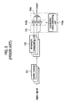
- a conventional ultrasound system generally includes a probe 110, a transmitting unit 120, a receiving unit 130, an intra-channel processing unit 140, a receiving focusing unit 150, an image processing unit 160, a displaying unit 170 and a controlling unit 180.
- the probe 110 includes a plurality of transducers.
- the receiving unit 130 and the intra-channel processing unit 140 are equipped and provided as much as the number of transducers.
- the transmitting unit 120 generates pulse voltages, which have different time delays, in consideration of the relative positions of the transducers.
- Each transducer 111 in the probe 110 receives the pulse voltage from the transmitting unit 120 and generates transmitting ultrasound signals.
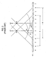
- the transmitting ultrasound signals from the transducers are focused on focal points on the transmission scan lines. Referring to FIG. 2 , the ultrasound signals generated from the transducers 4 to 4 in section A are focused on a focal point f0 at a scan line L0, while the ultrasound signals generated from the transducers -2 to 6 in section B arc focused on a focal point f2 at a scan line L2.
- Each transducer receives the ultrasound echoes originated from the ultrasound signals transmitted along the scan lines. For instance, some ultrasound signals transmitted from the transducer 0 along the scan line L0 arrive at a first point P1 when a time corresponding to a path Z1 passes. Then, the ultrasound signals are received at the transducer 0 as the ultrasound echoes when the time corresponding to the path Z1 passes again. Some ultrasound signals transmitted from the transducer 2 along the scan line L2 arrive at the first object point P1 when a time corresponding to a path Z2 passes. Then, the ultrasound signals are received at the transducer 0 as the ultrasound echoes when the time corresponding to the path Z1 passes. That is, the transducer 0 receives the ultrasound echoes, which are originated from the ultrasound signals transmitted along scan lines L0 and L2, respectively.
- transducers 111 convert the ultrasound echoes into the electric receiving analog signals.
- the receiving unit 130 amplifies the electric receiving analog signals and converts the amplified electric receiving analog signals into digital signals.
- the intra-channel processing unit 140 stores the digital signals of the respective scan lines, delays the digital signals and focuses the delayed digital signals.
- the intra-channel processing unit 140 includes buffer memories 141 equipped and provided as much as the number of scan lines, a delaying & interpolating units 142 corresponding to the buffer memories one by one and an apodizing unit 143.
- Each buffer memory 141 stores the digital signal inputted from the receiving unit 130.
- the digital signals which are obtained from the ultrasound echoes received at transducer 0, are separated according to the transmitting scan lines L0 and L2.
- the separated digital signals are stored in different buffer memories.
- the delaying & interpolating unit 142 delays the digital signals by considering the arriving time of ultrasound echoes at each transducer.
- An apodizing unit 143 includes an intra channel apodization value calculating unit 143a to provide appropriate weight values to the digital signals of each scan line, multiplying units 143b to apply the weight values to the digital signals and an adding unit 143c to sum the outputs from multiplying units 143c.
- the receiving focusing unit 150 includes an intra-channel apodization value calculating unit 151 to provide appropriate weight values to outputs of the intra channel processing unit 140, i.e., to the digital signals of each transducers, multiplying units 152 to apply the weight values to the digital signals and an adding unit 153 to sum the outputs from multiplying units 152 and to output the focused data of all the transducers 111.
- an intra-channel apodization value calculating unit 151 to provide appropriate weight values to outputs of the intra channel processing unit 140, i.e., to the digital signals of each transducers, multiplying units 152 to apply the weight values to the digital signals and an adding unit 153 to sum the outputs from multiplying units 152 and to output the focused data of all the transducers 111.
- the image processing unit 160 processes the focused data outputted from the receiving focusing unit 150 in various manners.
- the displaying unit 170 displays ultrasound images with the processed data.
- the controlling unit 180 controls the operations of transmitting unit 120 and the image processing unit 160.
- Each buffer memory 141 of the intra channel processing unit 140 in the conventional ultrasound system described above should have the storage capacity suitable for storing the digital signals per scan line. Generally, the storage capacity should be at least 60 Kbit. Further, the buffer memories 141 are required as much as the scan lines, conventionally over 128. Thus, each intra channel processing unit 140 should have a memory, the storage capacity of which surpasses 7 Mbit.
- FIG. 1 is a schematic diagram showing a conventional ultrasound imaging system.
- FIG. 2 is a diagram illustrating a conventional method of focusing ultrasound signals.
- FIG. 3 is a schematic diagram showing components of an intra-channel processing unit in the conventional ultrasound imaging system.
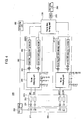
- FIG. 4 is a block diagram showing an ultrasound imaging system in accordance with an embodiment of the present invention.
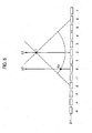
- FIG. 5 is a diagram illustrating receiving signals of each transducer of a probe in accordance with an embodiment of the present invention.
- FIG. 6 is a block diagram showing components of a focus delaying unit in accordance with an embodiment of the present invention.
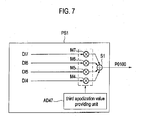
- FIG. 7 is a block diagram showing components of a supplement data forming unit in accordance with an embodiment of the present invention.
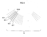
- FIG. 8 is a diagram illustrating forming the supplement data in accordance with an embodiment of the present invention.
- An ultrasound imaging system in accordance with the present invention forms scan lines and a frame with receiving signals obtained at each transducer in a probe.
- a probe 210 of an ultrasound imaging system 200 constructed in accordance with the present invention includes a plurality of transducers 211.
- the receiving signals of each transducer are electric analog signals, which are obtained with echoes of the ultrasound signals transmitted from at least one transducer to different focal points or the same focal point. For example, as shown in FIG.
- some ultrasound signals transmitted from a transducer 0 to a focal point f on a transmitting scan line 2 are reflected from a point 1 and arrive at the transducer 0 as first receiving ultrasound signals
- Another ultrasound signals transmitted from a transducer 2 to the focal point f are reflected from the same point P1 and arrive at the transducer 0 as second receiving ultrasound signals.
- the receiving signals of the transducer 0 are electric analog signals obtained with the first and second ultrasound signals.
- a transmitting unit 220 applies a pulse voltage to each transducer 211.
- the pulse voltages of the respective transducers have different delay times to which the relative positions of the transducers are reflected.
- a receiving unit 230 includes an amplifier 231 to amplify the electric receive signal outputted from the transducers 211 and an analog-digital converter (ADC) 232 to convert the amplified electrical receiving signals into digital signals.
- ADC analog-digital converter
- the digital signals outputted from the receiving unit 230 are referred to as receiving data.
- the amplifier 231 and the ADC 232 are equipped and provided as much as the number of transducers 211.
- Scan line data forming units 240 form the data of a plurality of scan lines by using the receiving data.
- Each scan line data forming unit 240 may be configured with an application-specific integrated circuit (ASIC).
- ASIC application-specific integrated circuit
- At least one main scan lines are assigned to the respective scan line data forming units 240.
- Each scan line data forming unit has different main scan lines, which are selected among all of the scan lines. The rest of the scan lines are the supplement scan lines of each scan line data forming unit 240.
- the scan lines 0 to 3 among scan lines 0 to 255, are the main scan lines of the ASIC 0 (i.e., the ASIC 0 is in charge of the scan lines 0 to 3).
- the rest of the scan lines i.e., scan lines 4 to 255, are the supplement scan lines of the ASIC 0.
- the number of main line(s) of each scan line data forming unit 240 may be equal or different. For instance, the same number of scan lines (i.e., four scan lines) may be assigned to the ASICs 0 to 63, or different numbers of main scan lines (e.g., two, three, four main scan lines, etc.) may be assigned to ASICs 0 to 63.
- the supplement scan lines of one scan line data forming unit may be the main scan lines of other scan line data forming units 240.
- the scan lines 4 to 7 are the main scan lines of the ASIC 1
- the scan lines 8 to 11 are the main scan line of the ASlC 2, etc.
- the scan lines 252 to 255 are the main scan lines of the ASlC 63.
- Each scan line data forming unit 240 forms a first supplement data and partial data of each main scan line with the receiving data formed with the receiving signals of the transducer corresponding thereto. As shown in FIG. 4 , when forming scan line data of 256 scan lines with 128 transducers and 64 scan line data forming units 240, 4 main scan lines and 252 supplement scan lines are assigned to each scan line data forming unit 240.
- the scan line data forming unit 240 receives the receiving data provided from the two different ADCs 232 and forms supplement data of the 252 supplement scan lines and the partial data of four main scan lines. Further, each scan line data forming unit forms scan line data of the four main scan lines with the partial data and second supplement data provided from other scan line data forming units.
- ASlC 0 forms the partial data of main scan lines 0 to 3 with the receiving data obtained from receiving signals from the two transducers corresponding thereto and the supplement data of the supplement scan lines 4 to 255 to be inputted to other scan line data forming units, i.e., ASICs 1 to 63.
- ASIC 0 forms scan line data of the main scan lines 04 to 3 with the partial data of the main scan lines 0 to 3 and second supplement data inputted from ASICs 1 to 63.
- ASIC 1 forms scan line data of main scan lines 4 to 7 with receiving data obtained from receiving signals from the two transducers corresponding thereto and the supplement data of the main scan lines 4 to 7 inputted from other scan line data forming units, i.e., ASICs 0 and ASIC 2 to 63-
- ASIC 2 forms supplement data of the supplement scan lines 1 to 3 and scan lines 8 to 255 to be provided to ASICs 0 and 2 to 63.
- each scan line data forming unit 240 includes a focus delaying unit 241, a register 242 and an adder 243.
- the focus delaying unit 241 delays and interpolates the receiving data of the respective scan lines to form the first supplement data and the partial data of the main scan lines.
- the focus delaying unit 241 applies the second supplement data provided by the other scan line data forming units to the partial data of the main scan lines.
- the register 242 and the adder 243 play a role of accumulator to accumulate the second supplement data and the partial data of the main scan lines.
- the output of the register is the scan line data of the main scan lines.
- the focus delaying unit 241 includes a focus delay amount providing unit 241a, a delaying & interpolating unit 241b and a supplement data forming unit 241.
- the focus delaying unit 241 also includes a first apodization value providing unit 241d, a first multiplying unit 241e, a second apodization value providing unit 241f, a second multiplying unit 241g and a transducer identifying unit 241h.
- the transducer identifying unit 241h identities a transducer among the transducers corresponding to each scan line data forming unit 241 and forms transducer information.
- the focus delay amount providing unit 241 a provides the focus delay amount of each scan line in consideration of the transducer information R1.
- FIG. 6 schematically shows a single focus delay amount providing unit 241a. However, a plurality of focus delay amount providing units is equipped in each scan line data forming as many as the main scan lines.
- the delaying & interpolating unit 241b reflects the focus delay amount to the receiving data in order to delay and interpolate the receive data of the respective scan lines.
- the delaying & interpolating units 241 are may be equipped and provided as much as the scan lines.
- one focus delay unit 241 includes 256 delay & interpolating units D10 to D1255, as shown in FIG. 6 .
- the supplement data forming units 241c correspond to other scan line data forming units 240.
- the number of supplement data forming units is equal to that of the other scan line data forming units. Referring to FIG.
- a supplement data forming unit PS1 in the ASlC 0 forms supplement data of supplement scan lines SC4 to SC7 to be transmitted to the ASIC 1.
- a third apodization value providing unit AD47, a plurality of multipliers M4 to M7 and an adder S1 are equipped in the supplement data forming unit PS1.
- the multipliers M4 to M7 apply the third apodization value to the delayed and interpolated receiving data of the supplement scan lines, wherein the adder S1 sums the outputs from all of the multipliers M4 to M7 to output the supplement data.
- the supplement data forming unit PS1 combines supplement data of the supplement scan lines SC4 to SC 7 to form combined-supplement data P0100.
- the former two digits "01” denote the ASIC 01 (ASIC 1) corresponding to the supplement data forming unit PS1, while the latter two digits "00” denote the ASIC 00(ASIC 0) to which the scan line data forming unit PS1 belongs.
- the first apodization value providing unit 214d receives the transducer information R from the transducer identifying unit 241h and provides the first apodivation values corresponding to the transducer, i.e., identified with the transducer information R, which provides the receiving signals.
- the first multipliers 242e which are equipped and provided as much as the number of main scan lines, reflect the first apodization value to the partial data of each main scan line.
- the first apodization value providing unit 241 of ASIC 0 provides the first apodization values of the respective main scan lines 0 to 3, while the first multiplying units 241e (i.e., MP0 to MP3) apply the first apodization value to the partial data of the main scan lines 0 to 3 respectively corresponding thereto.
- the second apodization value providing unit 241 f receives the transducer information R2 from the other scan line data forming units to provide the second apodization value.
- the second multipliers 241g which are equipped and provided as much as the main scan lines, apply the second apodization value to the second supplement scan line data provided from the other scan line data forming units.
- the second apodization value providing unit 241f in ASIC 0 provides the second apodization values
- the second multipliers 241 g i.e., M1 to M2
- the second multipliers 241 g which are equipped and provided as much as the main scan lines of ASIC 0 apply the second apodization value to the second supplement data provided from ASICs 1 to 63.
- the outputs of the focus delaying unit i.e., the partial data and the supplement data of the main scan lines, are accumulated with the register 242 and the adder 243-
- the final stored valued in the register 242 are outputted as the scan line data of the main scan lines.
- the supplement data provided from the other scan line data forming units are obtained from the receiving signals of different transducers.
- the focus delay unit 241 may further include a fine delay amount providing unit 241i and fine delaying units FD0 to FD3.
- the fine delay amount providing unit 241 i receives the transducer information R2 and provides a fine delay amount corresponding to the transducers.
- the fine delaying units PD0 to FD3 finely delays the supplement data, to which the second apodization values are applied.
- the frame data forming unit 250 forms frame data with the scan line data provided from all the scan line data forming units 240.
- a controlling unit 260 controls the input and output of signals of the transmitting unit 220 and the frame data forming unit 250.
- a digital scan converter 270 of the ultrasound imaging system 220 converts the frame data outputted from the frame data forming unit 250.
- the displaying unit 280 displays the ultrasound image with the scan converted frame data.
- a partial data of the main scan line and a first supplement data of the supplement scan line are formed with receive data obtained from receive signals from at least one transducer.
- the receiving signals of the transducer include first ultrasound echoes obtained with ultrasound signals transmitted from the transducer and second ultrasound echoes obtained with ultrasound signals transmitted from the other transducers.
- a second supplement data provided from other scan line data forming units is applied to the partial data of the main scan line to form a scan line data of the main scan line.
- the second supplement data and the partial data are accumulated to form the scan line data of the main scan line.
- each scan line data forming unit forms the scan line data of the main scan lines and the supplement scan line data.
- the required storage capacity may be reduced.
- the supplement data from another scan line data forming unit are provided in a combined form. As such, the data transmission amount between the scan line data forming units may be decreased.
- any reference in this specification to "one embodiment,” “an embodiznent,” “example embodiment,” etc. means that a particular feature, structure or characteristic described in connection with the embodiment is included in at least one embodiment of the present invention.
- the appearances of such phrases in various places in the specification are not necessarily all referring to the same embodiment.
Landscapes
- Engineering & Computer Science (AREA)
- Computer Networks & Wireless Communication (AREA)
- Physics & Mathematics (AREA)
- General Physics & Mathematics (AREA)
- Radar, Positioning & Navigation (AREA)
- Remote Sensing (AREA)
- Ultra Sonic Daignosis Equipment (AREA)
- Measurement Of Velocity Or Position Using Acoustic Or Ultrasonic Waves (AREA)
- Investigating Or Analyzing Materials By The Use Of Ultrasonic Waves (AREA)
Abstract
Description
- The present application claims priority from Korean Patent Application Nos.
10-2007-0036226 filed on April 13, 2007 10-2008-0033665 filed on April 11, 2008 - The present invention generally relates to ultrasound imaging systems, and more particularly to an ultrasound imaging system and a method of forming a plurality of scan lines and frames by using receiving signals provided by transducers in a probe.
- The ultrasound imaging system shows internal structures of a target object in a non-invasive and non-destructive manner. The ultrasound imaging system includes a probe to transmit and receive ultrasound signals and a beam former. In the probe, transducers are equipped to perform the mutual conversion of ultrasound signals and electric signals. When equipping a plurality of transducers, an outspread of the ultrasound can be prevented more effectively compared to a case of equipping a single transducer. Further, with the plurality of the transducers, the ultrasound signals can be focused and the sensitivity may be improved. The transducers may generate the ultrasound signals one by one. Alternatively, some transducers may generate the ultrasound signals at a time. The ultrasound signals transmitted from the transducers are reflected at a discontinuous surface of acoustic impedance, i.e., at a surface of a reflector in a target. Each transducer converts echo ultrasound signals into the electric signals.
- The ultrasound signals must be focused when transmitting and receiving. When transmitting, the transmission order of the transducers may be determined by considering the distance differences between the transducers and the focal point. Thus, the ultrasound signals transmitted from all of the transducers, which contribute to form one scan line, reach the focal point at the same time with the same phase. Accordingly, the focused ultrasound signals (i.e., the summation of ultrasound signals at the focal point) may have the maximum amplitude The ultrasound echoes reflected from the focal point reach each transducer at different times. Thus, when receiving, time delays are applied to the ultrasound echoes so that the echo ultrasound signals can be seen as those arriving simultaneously at the transducers with the same phase.
- A large number of focal points are required to improve the image resolution. However, this causes the degradation of the frame rate since the same procedures should be repeatedly performed as much as the number of focal points for forming an image. A receive dynamic focusing is introduced to solve the problem described above. According to the receive dynamic focusing, the number of focal points are fixed in transmission focusing, whereas the number of focal points are varied in receiving focusing in order to focus more finely. However, the improvement in resolution is also limited due to the fixed number of focal points when transmitting. In
U.S. Patent No. 6,231,511 , all the signals obtained by performing transmission focusing on a number of adjacent scan lines are used in the receiving focus. This is to obtain the same effect as the case where focal points exist in all the points on the scan line. - Referring to
FIG. 1 , a conventional ultrasound system generally includes aprobe 110, a transmittingunit 120, areceiving unit 130, anintra-channel processing unit 140, a receivingfocusing unit 150, animage processing unit 160, a displayingunit 170 and a controllingunit 180. Theprobe 110 includes a plurality of transducers. Thereceiving unit 130 and theintra-channel processing unit 140 are equipped and provided as much as the number of transducers. - The transmitting
unit 120 generates pulse voltages, which have different time delays, in consideration of the relative positions of the transducers. Eachtransducer 111 in theprobe 110 receives the pulse voltage from the transmittingunit 120 and generates transmitting ultrasound signals. The transmitting ultrasound signals from the transducers are focused on focal points on the transmission scan lines. Referring toFIG. 2 , the ultrasound signals generated from thetransducers 4 to 4 in section A are focused on a focal point f0 at a scan line L0, while the ultrasound signals generated from the transducers -2 to 6 in section B arc focused on a focal point f2 at a scan line L2. - Each transducer receives the ultrasound echoes originated from the ultrasound signals transmitted along the scan lines. For instance, some ultrasound signals transmitted from the
transducer 0 along the scan line L0 arrive at a first point P1 when a time corresponding to a path Z1 passes. Then, the ultrasound signals are received at thetransducer 0 as the ultrasound echoes when the time corresponding to the path Z1 passes again. Some ultrasound signals transmitted from thetransducer 2 along the scan line L2 arrive at the first object point P1 when a time corresponding to a path Z2 passes. Then, the ultrasound signals are received at thetransducer 0 as the ultrasound echoes when the time corresponding to the path Z1 passes. That is, thetransducer 0 receives the ultrasound echoes, which are originated from the ultrasound signals transmitted along scan lines L0 and L2, respectively. - Referring back to
FIG. 1 ,transducers 111 convert the ultrasound echoes into the electric receiving analog signals. Thereceiving unit 130 amplifies the electric receiving analog signals and converts the amplified electric receiving analog signals into digital signals. Theintra-channel processing unit 140 stores the digital signals of the respective scan lines, delays the digital signals and focuses the delayed digital signals. - Referring to
FIG. 3 , theintra-channel processing unit 140 includesbuffer memories 141 equipped and provided as much as the number of scan lines, a delaying & interpolatingunits 142 corresponding to the buffer memories one by one and an apodizingunit 143. Eachbuffer memory 141 stores the digital signal inputted from thereceiving unit 130. For example, the digital signals, which are obtained from the ultrasound echoes received attransducer 0, are separated according to the transmitting scan lines L0 and L2. Thus, the separated digital signals are stored in different buffer memories. The delaying & interpolatingunit 142 delays the digital signals by considering the arriving time of ultrasound echoes at each transducer. An apodizingunit 143 includes an intra channel apodizationvalue calculating unit 143a to provide appropriate weight values to the digital signals of each scan line, multiplyingunits 143b to apply the weight values to the digital signals and an addingunit 143c to sum the outputs from multiplyingunits 143c. - As shown in
FIG. 1 , the receiving focusingunit 150 includes an intra-channel apodizationvalue calculating unit 151 to provide appropriate weight values to outputs of the intrachannel processing unit 140, i.e., to the digital signals of each transducers, multiplyingunits 152 to apply the weight values to the digital signals and an addingunit 153 to sum the outputs from multiplyingunits 152 and to output the focused data of all thetransducers 111. - The
image processing unit 160 processes the focused data outputted from the receiving focusingunit 150 in various manners. The displayingunit 170 displays ultrasound images with the processed data. The controllingunit 180 controls the operations of transmittingunit 120 and theimage processing unit 160. - Each
buffer memory 141 of the intrachannel processing unit 140 in the conventional ultrasound system described above should have the storage capacity suitable for storing the digital signals per scan line. Generally, the storage capacity should be at least 60 Kbit. Further, thebuffer memories 141 are required as much as the scan lines, conventionally over 128. Thus, each intrachannel processing unit 140 should have a memory, the storage capacity of which surpasses 7 Mbit. -
FIG. 1 is a schematic diagram showing a conventional ultrasound imaging system. -
FIG. 2 is a diagram illustrating a conventional method of focusing ultrasound signals. -
FIG. 3 is a schematic diagram showing components of an intra-channel processing unit in the conventional ultrasound imaging system. -
FIG. 4 is a block diagram showing an ultrasound imaging system in accordance with an embodiment of the present invention. -
FIG. 5 is a diagram illustrating receiving signals of each transducer of a probe in accordance with an embodiment of the present invention. -
FIG. 6 is a block diagram showing components of a focus delaying unit in accordance with an embodiment of the present invention. -
FIG. 7 is a block diagram showing components of a supplement data forming unit in accordance with an embodiment of the present invention. -
FIG. 8 is a diagram illustrating forming the supplement data in accordance with an embodiment of the present invention. - An ultrasound imaging system in accordance with the present invention forms scan lines and a frame with receiving signals obtained at each transducer in a probe. Referring to
FIG. 4 , aprobe 210 of anultrasound imaging system 200 constructed in accordance with the present invention includes a plurality oftransducers 211. The receiving signals of each transducer are electric analog signals, which are obtained with echoes of the ultrasound signals transmitted from at least one transducer to different focal points or the same focal point. For example, as shown inFIG. 5 , some ultrasound signals transmitted from atransducer 0 to a focal point f on a transmittingscan line 2 are reflected from apoint 1 and arrive at thetransducer 0 as first receiving ultrasound signals- Another ultrasound signals transmitted from atransducer 2 to the focal point f are reflected from the same point P1 and arrive at thetransducer 0 as second receiving ultrasound signals. The receiving signals of thetransducer 0 are electric analog signals obtained with the first and second ultrasound signals. - A transmitting
unit 220 applies a pulse voltage to eachtransducer 211. The pulse voltages of the respective transducers have different delay times to which the relative positions of the transducers are reflected. - A receiving
unit 230 includes anamplifier 231 to amplify the electric receive signal outputted from thetransducers 211 and an analog-digital converter (ADC) 232 to convert the amplified electrical receiving signals into digital signals. Hereinafter, the digital signals outputted from the receivingunit 230 are referred to as receiving data. Theamplifier 231 and theADC 232 are equipped and provided as much as the number oftransducers 211. - Scan line
data forming units 240 form the data of a plurality of scan lines by using the receiving data. Each scan linedata forming unit 240 may be configured with an application-specific integrated circuit (ASIC). At least one main scan lines are assigned to the respective scan linedata forming units 240. Each scan line data forming unit has different main scan lines, which are selected among all of the scan lines. The rest of the scan lines are the supplement scan lines of each scan linedata forming unit 240. For example, thescan lines 0 to 3, amongscan lines 0 to 255, are the main scan lines of the ASIC 0 (i.e., theASIC 0 is in charge of thescan lines 0 to 3). The rest of the scan lines, i.e.,scan lines 4 to 255, are the supplement scan lines of theASIC 0. The number of main line(s) of each scan linedata forming unit 240 may be equal or different. For instance, the same number of scan lines (i.e., four scan lines) may be assigned to theASICs 0 to 63, or different numbers of main scan lines (e.g., two, three, four main scan lines, etc.) may be assigned toASICs 0 to 63. The supplement scan lines of one scan line data forming unit may be the main scan lines of other scan linedata forming units 240. For example, among thesupplement scan lines 4 to 255 of theASIC 0, thescan lines 4 to 7 are the main scan lines of theASIC 1, the scan lines 8 to 11 are the main scan line of theASlC 2, etc. Thus, thescan lines 252 to 255 are the main scan lines of the ASlC 63. - Each scan line
data forming unit 240 forms a first supplement data and partial data of each main scan line with the receiving data formed with the receiving signals of the transducer corresponding thereto. As shown inFIG. 4 , when forming scan line data of 256 scan lines with 128 transducers and 64 scan linedata forming units data forming unit 240. The scan linedata forming unit 240 receives the receiving data provided from the twodifferent ADCs 232 and forms supplement data of the 252 supplement scan lines and the partial data of four main scan lines. Further, each scan line data forming unit forms scan line data of the four main scan lines with the partial data and second supplement data provided from other scan line data forming units. For example,ASlC 0 forms the partial data ofmain scan lines 0 to 3 with the receiving data obtained from receiving signals from the two transducers corresponding thereto and the supplement data of thesupplement scan lines 4 to 255 to be inputted to other scan line data forming units, i.e.,ASICs 1 to 63. Also,ASIC 0 forms scan line data of the main scan lines 04 to 3 with the partial data of themain scan lines 0 to 3 and second supplement data inputted fromASICs 1 to 63. Similarly,ASIC 1 forms scan line data ofmain scan lines 4 to 7 with receiving data obtained from receiving signals from the two transducers corresponding thereto and the supplement data of themain scan lines 4 to 7 inputted from other scan line data forming units, i.e.,ASICs 0 andASIC 2 to 63- Also,ASIC 2 forms supplement data of thesupplement scan lines 1 to 3 and scan lines 8 to 255 to be provided toASICs - Referring back to
FIG. 4 , each scan linedata forming unit 240 includes afocus delaying unit 241, aregister 242 and anadder 243. Thefocus delaying unit 241 delays and interpolates the receiving data of the respective scan lines to form the first supplement data and the partial data of the main scan lines. Thefocus delaying unit 241 applies the second supplement data provided by the other scan line data forming units to the partial data of the main scan lines. Theregister 242 and theadder 243 play a role of accumulator to accumulate the second supplement data and the partial data of the main scan lines. The output of the register is the scan line data of the main scan lines. - Referring to
FIG. 6 , thefocus delaying unit 241 includes a focus delayamount providing unit 241a, a delaying & interpolatingunit 241b and a supplementdata forming unit 241. Thefocus delaying unit 241 also includes a first apodizationvalue providing unit 241d, a first multiplyingunit 241e, a second apodization value providing unit 241f, a second multiplyingunit 241g and atransducer identifying unit 241h. Thetransducer identifying unit 241h identities a transducer among the transducers corresponding to each scan linedata forming unit 241 and forms transducer information. For example, if theASIC 0 receives the receiving data obtained with the receiving signals provided from thetransducer ASIC 0 identifies which transducer provides the receiving signals between the twotransducers amount providing unit 241 a provides the focus delay amount of each scan line in consideration of the transducer information R1. For purposes of simplicity,FIG. 6 schematically shows a single focus delayamount providing unit 241a. However, a plurality of focus delay amount providing units is equipped in each scan line data forming as many as the main scan lines. The delaying & interpolatingunit 241b reflects the focus delay amount to the receiving data in order to delay and interpolate the receive data of the respective scan lines. In thefocus delaying unit 241, the delaying & interpolatingunits 241 are may be equipped and provided as much as the scan lines. For example, when forming the data of 256 scan lines, onefocus delay unit 241 includes 256 delay & interpolating units D10 to D1255, as shown inFIG. 6 . The supplementdata forming units 241c correspond to other scan linedata forming units 240. Thus, the number of supplement data forming units is equal to that of the other scan line data forming units. Referring toFIG. 7 , a supplement data forming unit PS1 in theASlC 0 forms supplement data of supplement scan lines SC4 to SC7 to be transmitted to theASIC 1. A third apodization value providing unit AD47, a plurality of multipliers M4 to M7 and an adder S1 are equipped in the supplement data forming unit PS1. The multipliers M4 to M7 apply the third apodization value to the delayed and interpolated receiving data of the supplement scan lines, wherein the adder S1 sums the outputs from all of the multipliers M4 to M7 to output the supplement data. Referring toFIG. 8 , the supplement data forming unit PS1 combines supplement data of the supplement scan lines SC4 toSC 7 to form combined-supplement data P0100. In the "P0100," the former two digits "01" denote the ASIC 01 (ASIC 1) corresponding to the supplement data forming unit PS1, while the latter two digits "00" denote the ASIC 00(ASIC 0) to which the scan line data forming unit PS1 belongs. - Referring once again to
FIG. 6 , the first apodization value providing unit 214d receives the transducer information R from thetransducer identifying unit 241h and provides the first apodivation values corresponding to the transducer, i.e., identified with the transducer information R, which provides the receiving signals. The first multipliers 242e, which are equipped and provided as much as the number of main scan lines, reflect the first apodization value to the partial data of each main scan line. For example, the first apodizationvalue providing unit 241 ofASIC 0 provides the first apodization values of the respectivemain scan lines 0 to 3, while the first multiplyingunits 241e (i.e., MP0 to MP3) apply the first apodization value to the partial data of themain scan lines 0 to 3 respectively corresponding thereto. - The second apodization value providing unit 241 f receives the transducer information R2 from the other scan line data forming units to provide the second apodization value. The
second multipliers 241g, which are equipped and provided as much as the main scan lines, apply the second apodization value to the second supplement scan line data provided from the other scan line data forming units. For example, the second apodization value providing unit 241f inASIC 0 provides the second apodization values, while thesecond multipliers 241 g (i.e., M1 to M2), which are equipped and provided as much as the main scan lines ofASIC 0, apply the second apodization value to the second supplement data provided fromASICs 1 to 63. - The outputs of the focus delaying unit, i.e., the partial data and the supplement data of the main scan lines, are accumulated with the
register 242 and the adder 243- The final stored valued in theregister 242 are outputted as the scan line data of the main scan lines. - The supplement data provided from the other scan line data forming units are obtained from the receiving signals of different transducers. In order to compensate the difference of the transducers, the
focus delay unit 241 may further include a fine delayamount providing unit 241i and fine delaying units FD0 to FD3. The fine delayamount providing unit 241 i receives the transducer information R2 and provides a fine delay amount corresponding to the transducers. The fine delaying units PD0 to FD3 finely delays the supplement data, to which the second apodization values are applied. - Referring back to
FIG. 4 , the framedata forming unit 250 forms frame data with the scan line data provided from all the scan linedata forming units 240. A controllingunit 260 controls the input and output of signals of the transmittingunit 220 and the framedata forming unit 250. Adigital scan converter 270 of theultrasound imaging system 220 converts the frame data outputted from the framedata forming unit 250. The displayingunit 280 displays the ultrasound image with the scan converted frame data. - In accordance with a method of forming scan line data with a plurality of scan line data forming units in an ultrasound imaging system, a partial data of the main scan line and a first supplement data of the supplement scan line are formed with receive data obtained from receive signals from at least one transducer. The receiving signals of the transducer include first ultrasound echoes obtained with ultrasound signals transmitted from the transducer and second ultrasound echoes obtained with ultrasound signals transmitted from the other transducers. A second supplement data provided from other scan line data forming units is applied to the partial data of the main scan line to form a scan line data of the main scan line. The second supplement data and the partial data are accumulated to form the scan line data of the main scan line.
- In accordance with the present invention, each scan line data forming unit forms the scan line data of the main scan lines and the supplement scan line data. Thus, the required storage capacity may be reduced. Further, the supplement data from another scan line data forming unit are provided in a combined form. As such, the data transmission amount between the scan line data forming units may be decreased.
- Any reference in this specification to "one embodiment," "an embodiznent," "example embodiment," etc. means that a particular feature, structure or characteristic described in connection with the embodiment is included in at least one embodiment of the present invention. The appearances of such phrases in various places in the specification are not necessarily all referring to the same embodiment. Further, when a particular feature, structure or characteristic is described in connection with any embodiment, it is submitted that it is within the purview of one skilled in the art to effect such feature, structure or characteristic in connection with other ones of the embodiments.
- Although embodiments have been described with reference to a number of illustrative embodiments thereof, it should be understood that numerous other modifications and embodiments can be devised by those skilled in the art that will fall within the spirit and scope of the principles of this disclosure. More particularly, numerous variations and modifications are possible in the component parts and/or arrangements of the subject combination arrangement within the scope of the disclosure, the drawings and the appended claims. In addition to variations and modifications in the component parts and/or arrangements, alternative uses will also be apparent to those skilled in the art.
Claims (10)
- An ultrasound imaging system for forming a plurality of scan lines and frames, comprising:a probe including transducers for providing analog receiving signals;a receiving unit for converting the receiving signals into digital signals and providing receiving data;a plurality of scan line data forming units for forming scan line data of main scan lines and supplement data of supplement scan lines, wherein the main scan lines of each scan line data forming unit are ones of the scan lines and the supplement scan lines are determined with the others; anda scan line data forming unit for receiving the scan line data from all of the scan line data forming units and for forming frame data,wherein the scan line data forming unit forms first supplement data of each supplement scan line and a partial data of said each main scan line and applies second supplement data provided from other scan line data forming units to form the scan line data of the main scan lines.
- The ultrasound imaging system of Claim 1, wherein the scan line data forming units have different main scan lines.
- The ultrasound imaging system of Claim 1, wherein each scan line data forming unit includes:a focus delaying unit to focus and delay the receive data of the respective scan lines and to form the first supplement scan line; andan accumulator to accumulate the second supplement data and the partial data of the main scan line to form the scan line data of the main scan line.
- The ultrasound imaging system of Claim 3, wherein the focus delaying unit includes:a transducer identifying unit to identify a transducer providing the receiving signals and to form a first transducer information;a focus delay amount providing unit to receive the first transducer information and to provide focus delay amount corresponding to the transducer providing the receiving signals;a delaying and interpolating unit to receive the focus delay amount and to delay and interpolate the receive data of the respective scan lines;a first apodization value providing unit to receive the first transducer information and to provide the first apodization value corresponding to the transducer providing the receiving signals;a first multiplying unit to apply the first apodization value to the receive data of the main scan lines;a plurality supplement data forming unit corresponding to other scan line data forming unit;a second apodization value providing unit to receive second transducer information from said scan line data forming units and to provide second apodization value in consideration of the second transducer information; anda second multiplying unit to apply the second apodization value to the second supplement data of the main scan lines.
- The ultrasound imaging system of Claim 3, wherein the focus delaying unit further includes:a fine delay amount providing unit to receive the second transducer information and to provide a fine delay amount of the second supplement data in consideration of the second transducer information.
- The ultrasound imaging system of Claim 3, wherein each supplement data forming unit includes:a third apodization value providing unit;a third multiplying unit to apply the third apodization value to the receive data of the supplement scan lines; andan adder to sum outputs from the third multiplying unit and to form the supplement data.
- The ultrasound imaging system of Claim 1, wherein the receiving signals of the transducer includes a first ultrasound echoes obtained with ultrasound signals transmitted from the transducer and a second ultrasound echoes obtained with ultrasound signals transmitted from other transducers.
- A method of forming scan line data with a plurality of scan line data forming units in an ultrasound imaging system, wherein said each scan line data forming unit has main scan line selected one among the scan lines and supplement scan lines determined with the others, the method comprising:forming a partial data of the main scan line and a first supplement data of the supplement scan line with receive data obtained from receive signals from at least one transducer;applying a second supplement data provided from other scan line data forming units to the partial data of the main scan Line to form a scan line data of the main scan line.
- The method of Claim 8, wherein the second supplement data and the partial data are accumulated to form the scan line data of the main scan line.
- The method of Claim 8, wherein the receiving signals of the transducer includes a first ultrasound echoes obtained with ultrasound signals transmitted from the transducer and a second ultrasound echoes obtained with ultrasound signals transmitted from other transducers.
Applications Claiming Priority (2)
| Application Number | Priority Date | Filing Date | Title |
|---|---|---|---|
| KR20070036226 | 2007-04-13 | ||
| KR1020080033665A KR100930569B1 (en) | 2007-04-13 | 2008-04-11 | Ultrasound Imaging System and Scanline Data Formation Method |
Publications (3)
| Publication Number | Publication Date |
|---|---|
| EP1980872A2 true EP1980872A2 (en) | 2008-10-15 |
| EP1980872A3 EP1980872A3 (en) | 2013-04-24 |
| EP1980872B1 EP1980872B1 (en) | 2018-08-22 |
Family
ID=39672110
Family Applications (1)
| Application Number | Title | Priority Date | Filing Date |
|---|---|---|---|
| EP08007201.0A Active EP1980872B1 (en) | 2007-04-13 | 2008-04-11 | System of forming ultrasound image and method of forming scan line data |
Country Status (3)
| Country | Link |
|---|---|
| US (1) | US8968202B2 (en) |
| EP (1) | EP1980872B1 (en) |
| JP (1) | JP5483827B2 (en) |
Cited By (1)
| Publication number | Priority date | Publication date | Assignee | Title |
|---|---|---|---|---|
| EP2248469A3 (en) * | 2009-04-30 | 2012-12-26 | Medison Co., Ltd. | Ultrasound system and method for ultrasound data |
Families Citing this family (2)
| Publication number | Priority date | Publication date | Assignee | Title |
|---|---|---|---|---|
| KR101097594B1 (en) * | 2009-04-30 | 2011-12-22 | 삼성메디슨 주식회사 | Ultrasound system and method for ultrasound data |
| WO2016159418A1 (en) * | 2015-04-02 | 2016-10-06 | 알피니언메디칼시스템 주식회사 | Method for generating ultrasonic image and device therefor |
Citations (1)
| Publication number | Priority date | Publication date | Assignee | Title |
|---|---|---|---|---|
| US6231511B1 (en) | 1997-11-10 | 2001-05-15 | Medison Co., Ltd. | Ultrasonic signal focusing method and apparatus for ultrasonic imaging system |
Family Cites Families (9)
| Publication number | Priority date | Publication date | Assignee | Title |
|---|---|---|---|---|
| US5793701A (en) * | 1995-04-07 | 1998-08-11 | Acuson Corporation | Method and apparatus for coherent image formation |
| US5544655A (en) * | 1994-09-16 | 1996-08-13 | Atlantis Diagnostics International, Llc | Ultrasonic multiline beamforming with interleaved sampling |
| JPH08289891A (en) | 1995-04-24 | 1996-11-05 | Olympus Optical Co Ltd | Ultrasonic diagnostic device |
| US6432056B1 (en) * | 1999-10-08 | 2002-08-13 | Atl Ultrasound | Ultrasonic diagnostic imaging system with high frame rate synthetic transmit focus |
| JP3559774B2 (en) | 2000-06-10 | 2004-09-02 | 株式会社 メディソン | Ultrasonic receiving beam forming apparatus using multi-stage delay elements |
| US6695783B2 (en) | 2000-12-22 | 2004-02-24 | Koninklijke Philips Electronics N.V. | Multiline ultrasound beamformers |
| DE602004002523T2 (en) * | 2003-06-25 | 2007-05-10 | Aloka Co. Ltd., Mitaka | Diagnostic ultrasound imaging device with a 2D transducer with variable subarrays |
| US20080092660A1 (en) * | 2004-06-30 | 2008-04-24 | Koninklijke Philips Electronics, N.V. | Multi-line beamforming extention using sub-arrays |
| US7918797B2 (en) * | 2006-05-23 | 2011-04-05 | Medison Co., Ltd. | Ultrasound diagnostic system and method for forming multiple receiving scan lines |
-
2008
- 2008-04-11 US US12/101,643 patent/US8968202B2/en active Active
- 2008-04-11 EP EP08007201.0A patent/EP1980872B1/en active Active
- 2008-04-14 JP JP2008104996A patent/JP5483827B2/en not_active Expired - Fee Related
Patent Citations (1)
| Publication number | Priority date | Publication date | Assignee | Title |
|---|---|---|---|---|
| US6231511B1 (en) | 1997-11-10 | 2001-05-15 | Medison Co., Ltd. | Ultrasonic signal focusing method and apparatus for ultrasonic imaging system |
Cited By (1)
| Publication number | Priority date | Publication date | Assignee | Title |
|---|---|---|---|---|
| EP2248469A3 (en) * | 2009-04-30 | 2012-12-26 | Medison Co., Ltd. | Ultrasound system and method for ultrasound data |
Also Published As
| Publication number | Publication date |
|---|---|
| JP2008259863A (en) | 2008-10-30 |
| JP5483827B2 (en) | 2014-05-07 |
| EP1980872A3 (en) | 2013-04-24 |
| US20080255454A1 (en) | 2008-10-16 |
| US8968202B2 (en) | 2015-03-03 |
| EP1980872B1 (en) | 2018-08-22 |
Similar Documents
| Publication | Publication Date | Title |
|---|---|---|
| US5579770A (en) | Multiple transmit zone splicing | |
| US5462057A (en) | Ultrasound imaging system using line splicing and parallel receive beam formation | |
| US8416643B2 (en) | Receive beamformer for ultrasound having delay value sorting | |
| KR100280197B1 (en) | Ultrasonic Signal Concentration Method and Apparatus in Ultrasonic Imaging System | |
| US6695783B2 (en) | Multiline ultrasound beamformers | |
| CN110101411B (en) | Ultrasonic imaging space compounding method and system | |
| CN108024798B (en) | Ultrasonic diagnostic apparatus and delay data generating method | |
| US11484292B2 (en) | Ultrasound signal processing device that uses synthetic aperture method and delay and sum method | |
| JP2007313319A (en) | Ultrasonic diagnostic apparatus and method for forming multiple reception scan lines | |
| US7993270B2 (en) | Digital receive-focusing apparatus using analogue multiplexers | |
| EP1980872B1 (en) | System of forming ultrasound image and method of forming scan line data | |
| JP2012115667A (en) | Ultrasonic system and method by which accommodative frame averaging process is performed | |
| JPH03123879A (en) | Ultrasonic echo graph apparatus | |
| KR100930569B1 (en) | Ultrasound Imaging System and Scanline Data Formation Method | |
| US20090171214A1 (en) | Ultrasound system and method of forming ultrasound image signals with multiprocessing | |
| JP2001224589A (en) | Ultrasonic imaging system and method | |
| US5891041A (en) | Ultrasonic imaging system adapted for use with ultrasonic probes having different center frequencies | |
| WO2000010463A1 (en) | Ultrasonic diagnostic apparatus | |
| KR100890376B1 (en) | Ultrasound diagnostic system and method for forming multiple receiving scan lines | |
| US11000260B2 (en) | Ultrasonic imaging apparatus and method of controlling ultrasonic imaging apparatus | |
| JP2008259863A5 (en) | ||
| JP3253287B2 (en) | Ultrasound diagnostic equipment | |
| KR100350025B1 (en) | Apparatus and method for expanding ultrasound images using synthetic write zoom technique | |
| JPH119603A (en) | Ultrasonic diagnostic device | |
| RU125451U1 (en) | ADAPTIVE DIAGRAM-FORMING DEVICE FOR RECEIVING ULTRASONIC SIGNALS |
Legal Events
| Date | Code | Title | Description |
|---|---|---|---|
| PUAI | Public reference made under article 153(3) epc to a published international application that has entered the european phase |
Free format text: ORIGINAL CODE: 0009012 |
|
| AK | Designated contracting states |
Kind code of ref document: A2 Designated state(s): AT BE BG CH CY CZ DE DK EE ES FI FR GB GR HR HU IE IS IT LI LT LU LV MC MT NL NO PL PT RO SE SI SK TR |
|
| AX | Request for extension of the european patent |
Extension state: AL BA MK RS |
|
| PUAL | Search report despatched |
Free format text: ORIGINAL CODE: 0009013 |
|
| AK | Designated contracting states |
Kind code of ref document: A3 Designated state(s): AT BE BG CH CY CZ DE DK EE ES FI FR GB GR HR HU IE IS IT LI LT LU LV MC MT NL NO PL PT RO SE SI SK TR |
|
| AX | Request for extension of the european patent |
Extension state: AL BA MK RS |
|
| RIC1 | Information provided on ipc code assigned before grant |
Ipc: G01S 7/52 20060101AFI20130320BHEP |
|
| 17P | Request for examination filed |
Effective date: 20131024 |
|
| RBV | Designated contracting states (corrected) |
Designated state(s): AT BE BG CH CY CZ DE DK EE ES FI FR GB GR HR HU IE IS IT LI LT LU LV MC MT NL NO PL PT RO SE SI SK TR |
|
| AKX | Designation fees paid |
Designated state(s): DE FR IT NL |
|
| 17Q | First examination report despatched |
Effective date: 20161117 |
|
| GRAP | Despatch of communication of intention to grant a patent |
Free format text: ORIGINAL CODE: EPIDOSNIGR1 |
|
| INTG | Intention to grant announced |
Effective date: 20180418 |
|
| GRAS | Grant fee paid |
Free format text: ORIGINAL CODE: EPIDOSNIGR3 |
|
| RAP1 | Party data changed (applicant data changed or rights of an application transferred) |
Owner name: SAMSUNG MEDISON CO., LTD. |
|
| GRAA | (expected) grant |
Free format text: ORIGINAL CODE: 0009210 |
|
| AK | Designated contracting states |
Kind code of ref document: B1 Designated state(s): DE FR IT NL |
|
| REG | Reference to a national code |
Ref country code: DE Ref legal event code: R096 Ref document number: 602008056574 Country of ref document: DE |
|
| REG | Reference to a national code |
Ref country code: NL Ref legal event code: FP |
|
| REG | Reference to a national code |
Ref country code: DE Ref legal event code: R097 Ref document number: 602008056574 Country of ref document: DE |
|
| PLBE | No opposition filed within time limit |
Free format text: ORIGINAL CODE: 0009261 |
|
| STAA | Information on the status of an ep patent application or granted ep patent |
Free format text: STATUS: NO OPPOSITION FILED WITHIN TIME LIMIT |
|
| 26N | No opposition filed |
Effective date: 20190523 |
|
| PGFP | Annual fee paid to national office [announced via postgrant information from national office to epo] |
Ref country code: NL Payment date: 20200306 Year of fee payment: 13 |
|
| REG | Reference to a national code |
Ref country code: NL Ref legal event code: MM Effective date: 20210501 |
|
| PG25 | Lapsed in a contracting state [announced via postgrant information from national office to epo] |
Ref country code: NL Free format text: LAPSE BECAUSE OF NON-PAYMENT OF DUE FEES Effective date: 20210501 |
|
| PGFP | Annual fee paid to national office [announced via postgrant information from national office to epo] |
Ref country code: FR Payment date: 20250307 Year of fee payment: 18 |
|
| PGFP | Annual fee paid to national office [announced via postgrant information from national office to epo] |
Ref country code: IT Payment date: 20250306 Year of fee payment: 18 |
|
| PGFP | Annual fee paid to national office [announced via postgrant information from national office to epo] |
Ref country code: DE Payment date: 20250305 Year of fee payment: 18 |