EP1980721A2 - Variable stator vane assembly for a turbine engine - Google Patents
Variable stator vane assembly for a turbine engine Download PDFInfo
- Publication number
- EP1980721A2 EP1980721A2 EP08251043A EP08251043A EP1980721A2 EP 1980721 A2 EP1980721 A2 EP 1980721A2 EP 08251043 A EP08251043 A EP 08251043A EP 08251043 A EP08251043 A EP 08251043A EP 1980721 A2 EP1980721 A2 EP 1980721A2
- Authority
- EP
- European Patent Office
- Prior art keywords
- bushing
- bore
- stator assembly
- stator
- assembly according
- Prior art date
- Legal status (The legal status is an assumption and is not a legal conclusion. Google has not performed a legal analysis and makes no representation as to the accuracy of the status listed.)
- Granted
Links
Images

Classifications
-
- F—MECHANICAL ENGINEERING; LIGHTING; HEATING; WEAPONS; BLASTING
- F01—MACHINES OR ENGINES IN GENERAL; ENGINE PLANTS IN GENERAL; STEAM ENGINES
- F01D—NON-POSITIVE DISPLACEMENT MACHINES OR ENGINES, e.g. STEAM TURBINES
- F01D17/00—Regulating or controlling by varying flow
- F01D17/10—Final actuators
- F01D17/12—Final actuators arranged in stator parts
- F01D17/14—Final actuators arranged in stator parts varying effective cross-sectional area of nozzles or guide conduits
- F01D17/16—Final actuators arranged in stator parts varying effective cross-sectional area of nozzles or guide conduits by means of nozzle vanes
- F01D17/162—Final actuators arranged in stator parts varying effective cross-sectional area of nozzles or guide conduits by means of nozzle vanes for axial flow, i.e. the vanes turning around axes which are essentially perpendicular to the rotor centre line
-
- F—MECHANICAL ENGINEERING; LIGHTING; HEATING; WEAPONS; BLASTING
- F05—INDEXING SCHEMES RELATING TO ENGINES OR PUMPS IN VARIOUS SUBCLASSES OF CLASSES F01-F04
- F05D—INDEXING SCHEME FOR ASPECTS RELATING TO NON-POSITIVE-DISPLACEMENT MACHINES OR ENGINES, GAS-TURBINES OR JET-PROPULSION PLANTS
- F05D2260/00—Function
- F05D2260/30—Retaining components in desired mutual position
- F05D2260/37—Retaining components in desired mutual position by a press fit connection
-
- Y—GENERAL TAGGING OF NEW TECHNOLOGICAL DEVELOPMENTS; GENERAL TAGGING OF CROSS-SECTIONAL TECHNOLOGIES SPANNING OVER SEVERAL SECTIONS OF THE IPC; TECHNICAL SUBJECTS COVERED BY FORMER USPC CROSS-REFERENCE ART COLLECTIONS [XRACs] AND DIGESTS
- Y10—TECHNICAL SUBJECTS COVERED BY FORMER USPC
- Y10T—TECHNICAL SUBJECTS COVERED BY FORMER US CLASSIFICATION
- Y10T29/00—Metal working
- Y10T29/49—Method of mechanical manufacture
- Y10T29/49316—Impeller making
- Y10T29/4932—Turbomachine making
- Y10T29/49323—Assembling fluid flow directing devices, e.g., stators, diaphragms, nozzles
Definitions
- This application relates to a bearing for use in supporting a stator trunnion. This application also relates to a method of installing the bearing into a support structure.
- a turbine engine typically includes multiple compressor stages. Circumferentially arranged stators are arranged axially adjacent to the compressor blades, which are supported by a rotor. Some compressors utilize variable stator vanes in which the stators are supported for rotation by an outer case. The stator vanes are actuated between multiple angular positions to change the operating characteristics of the compressor.
- An outer diameter of the stator vane includes a trunnion that is supported by a bushing in the outer case.
- the outer case includes an axially outwardly extending boss providing a bore that receives the bushing.
- One typical bushing includes a two-piece construction.
- An outer titanium sleeve is press-fit within the bore.
- a transfer molded composite bearing liner for example a braided carbon fiber polyimide resin, is arranged at the inner diameter of the titanium sleeve. The composite bearing liner provides a low friction surface for supporting the trunnion.
- An example stator assembly for a turbine engine disclosed herein includes a support structure, such as an outer case, providing a bore.
- a non-metallic bushing is arranged in the bore and extends radially between inner and outer diameters providing a one-piece structure. The outer diameter of the bushing engages the bore in a press-fit relationship, in one example.
- a stator includes a trunnion arranged within and engaging the bushing inner diameter.
- the non-metallic bushing is constructed from an electrographitic carbon. The bushing is installed into the bore such that an end of the bushing is generally flush with or recessed from a wall on the support structure.
- FIG. 1 One example turbine engine 10 is shown schematically in Figure 1 .
- a fan section moves air and rotates about an axis A.
- a compressor section, a combustion section, and a turbine section are also centered on the axis A.
- Figure 1 is a highly schematic view, however, it does show the main components of the gas turbine engine. Further, while a particular type of gas turbine engine is illustrated in this figure, it should be understood that the claim scope extends to other types of gas turbine engines, including geared turbofan engines.
- the engine 10 includes a low spool 12 rotatable about an axis A.
- the low spool 12 is coupled to a fan 14, a low pressure compressor 16, and a low pressure turbine 24.
- a high spool 13 is arranged concentrically about the low spool 12.
- the high spool 13 is coupled to a high pressure compressor 17 and a high pressure turbine 22.
- a combustor 18 is arranged between the high pressure compressor 17 and the high pressure turbine 22.
- the high pressure turbine 22 and low pressure turbine 24 typically each include multiple turbine stages.
- a hub supports each stage on its respective spool. Multiple turbine blades are supported circumferentially on the hub.
- High pressure and low pressure turbine blades 20, 21 are shown schematically at the high pressure and low pressure turbines 22, 24.
- Stator vanes 26 are arranged between the different blade stages and may be of fixed or variable geometry.
- stator vane 26 includes inner and outer trunnions 34, 30 respectively supported by an inner and outer case 32, 28.
- the outer case 28 (also shown schematically in Figure 1 ) includes a recess 38 that accommodates an outer platform 36 at a junction between the outer trunnion 30 and vane 26.
- the outer case 28 includes a boss 39 extending radially outward from the recess 38.
- the boss 39 has a bore 40 that receives a bushing 44 in a press-fit relationship.
- a chamfer 42 interconnects and extends between the recess 38 and bore 40 to facilitate installation of the bushing 44 into the outer case 28.
- an engine may include variable stator vanes arranged at multiple axial compressor stages 27a-27c.
- the bushing 44 is a unified construction of a non-metallic material.
- the non-metallic material extends radially from an inner diameter surface 52, which engages an outer trunnion outer diameter surface 50, to an outer diameter surface 54 that engages the bore 40.
- the bushing 44 is constructed from an electrographitic carbon.
- One type of electrographitic carbon is sintered to approximately 4,000°F (2204°C) during its formation. The electrographitic carbon can be brittle and subject to fracture if unsupported. To this end, it is desirable to install the bushing 44 into the bore 40 so that one or both of ends 46, 48 are supported within the bore 40.
- the bushing 44 is initially arranged at the inner diameter of the outer case 28 for installation.
- a tool typically employed for bushing installation can be used.
- an adapter 62 having a protrusion 66 is also provided to ensure the inner end 46 of the bushing 44 is installed to a desired radial depth 68, in one example, that does not leave the end 46 undesirably exposed and unsupported.
- the inner end 46 is generally flush with the intersection of the chamfer 42 and bore 40.
- a shoulder 70 of the adapter 62 seats against a wall 72 provided by a bottom of the recess 38. The inner end 46 is recessed from the wall 72.
- a sleeve 56 In operation, during installation, a sleeve 56 abuts the boss 39.
- a spacer 60 is arranged adjacent to the sleeve 56 opposite the boss 39.
- a threaded fastener 58 extends through the spacer 60, sleeve 56, bushing 44 and adapter 62.
- a nut 64 is secured to the fastener 58 near the adapter 62.
- the fastener 58 is tightened to draw the bushing 44 into the bore 40 in an interference fit.
- the shoulder 70 seats against the wall 72 thereby ensuring that the bushing 44 has been inserted into the bore 40 to the desired radial depth 68, thus ensuring adequate support to prevent damage.
- other installation tooling arrangements may be used.
Landscapes
- Engineering & Computer Science (AREA)
- Mechanical Engineering (AREA)
- General Engineering & Computer Science (AREA)
- Structures Of Non-Positive Displacement Pumps (AREA)
- Turbine Rotor Nozzle Sealing (AREA)
- Control Of Turbines (AREA)
Abstract
Description
- This application relates to a bearing for use in supporting a stator trunnion. This application also relates to a method of installing the bearing into a support structure.
- A turbine engine typically includes multiple compressor stages. Circumferentially arranged stators are arranged axially adjacent to the compressor blades, which are supported by a rotor. Some compressors utilize variable stator vanes in which the stators are supported for rotation by an outer case. The stator vanes are actuated between multiple angular positions to change the operating characteristics of the compressor.
- An outer diameter of the stator vane includes a trunnion that is supported by a bushing in the outer case. The outer case includes an axially outwardly extending boss providing a bore that receives the bushing. One typical bushing includes a two-piece construction. An outer titanium sleeve is press-fit within the bore. A transfer molded composite bearing liner, for example a braided carbon fiber polyimide resin, is arranged at the inner diameter of the titanium sleeve. The composite bearing liner provides a low friction surface for supporting the trunnion.
- Excessive temperatures in the compressor significantly degrade the resin binder and thereby reduce the bushing's life. Typically, the bushing degrades by delaminating or disintegrating when subjected to sustained temperatures at these excessive temperatures. Once the bearing liner fails, the titanium sleeve begins to wear and the vane angle is affected. What is needed is a bushing with greater heat tolerance and extended life.
- An example stator assembly for a turbine engine disclosed herein includes a support structure, such as an outer case, providing a bore. A non-metallic bushing is arranged in the bore and extends radially between inner and outer diameters providing a one-piece structure. The outer diameter of the bushing engages the bore in a press-fit relationship, in one example. A stator includes a trunnion arranged within and engaging the bushing inner diameter. In one example, the non-metallic bushing is constructed from an electrographitic carbon. The bushing is installed into the bore such that an end of the bushing is generally flush with or recessed from a wall on the support structure.
- These and other features of the application can be best understood from the following specification and drawings, the following of which is a brief description.
-
-
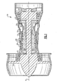
Figure 1 is a simplified cross-sectional view of an example turbine engine. -
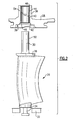
Figure 2 is an exploded view of a variable stator assembly. -
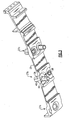
Figure 3 is a perspective sectional view of a portion of an outer case with a bushing for supporting the stator prior to installation. -
Figure 4A is a cross-sectional view of an installation tool with the bushing in an installed position. -
Figure 4B is a cross-sectional view of the installation tool and bushing prior to the bushing positioned in the installed position. - One
example turbine engine 10 is shown schematically inFigure 1 . As known, a fan section moves air and rotates about an axis A. A compressor section, a combustion section, and a turbine section are also centered on the axis A.Figure 1 is a highly schematic view, however, it does show the main components of the gas turbine engine. Further, while a particular type of gas turbine engine is illustrated in this figure, it should be understood that the claim scope extends to other types of gas turbine engines, including geared turbofan engines. - The
engine 10 includes alow spool 12 rotatable about an axis A. Thelow spool 12 is coupled to afan 14, alow pressure compressor 16, and a low pressure turbine 24. A high spool 13 is arranged concentrically about thelow spool 12. The high spool 13 is coupled to a high pressure compressor 17 and ahigh pressure turbine 22. A combustor 18 is arranged between the high pressure compressor 17 and thehigh pressure turbine 22. - The
high pressure turbine 22 and low pressure turbine 24 typically each include multiple turbine stages. A hub supports each stage on its respective spool. Multiple turbine blades are supported circumferentially on the hub. High pressure and lowpressure turbine blades 20, 21 are shown schematically at the high pressure andlow pressure turbines 22, 24.Stator vanes 26 are arranged between the different blade stages and may be of fixed or variable geometry. - Referring to
Figure 2 , onevariable stator vane 26 is shown in more detail. Thestator vane 26 includes inner andouter trunnions outer case Figure 1 ) includes arecess 38 that accommodates anouter platform 36 at a junction between theouter trunnion 30 andvane 26. - Referring to
Figures 2 and3 , theouter case 28 includes aboss 39 extending radially outward from therecess 38. Theboss 39 has abore 40 that receives a bushing 44 in a press-fit relationship. Achamfer 42 interconnects and extends between therecess 38 and bore 40 to facilitate installation of thebushing 44 into theouter case 28. As shown inFigure 3 , an engine may include variable stator vanes arranged at multipleaxial compressor stages 27a-27c. - In one example, the
bushing 44 is a unified construction of a non-metallic material. The non-metallic material extends radially from aninner diameter surface 52, which engages an outer trunnionouter diameter surface 50, to anouter diameter surface 54 that engages thebore 40. In one example, thebushing 44 is constructed from an electrographitic carbon. One type of electrographitic carbon is sintered to approximately 4,000°F (2204°C) during its formation. The electrographitic carbon can be brittle and subject to fracture if unsupported. To this end, it is desirable to install thebushing 44 into thebore 40 so that one or both ofends bore 40. - Referring to
Figures 4A and 4B , thebushing 44 is initially arranged at the inner diameter of theouter case 28 for installation. A tool typically employed for bushing installation can be used. However, anadapter 62 having a protrusion 66 is also provided to ensure theinner end 46 of thebushing 44 is installed to a desiredradial depth 68, in one example, that does not leave theend 46 undesirably exposed and unsupported. In one example, theinner end 46 is generally flush with the intersection of thechamfer 42 and bore 40. Ashoulder 70 of theadapter 62 seats against awall 72 provided by a bottom of therecess 38. Theinner end 46 is recessed from thewall 72. - In operation, during installation, a
sleeve 56 abuts theboss 39. Aspacer 60 is arranged adjacent to thesleeve 56 opposite theboss 39. A threadedfastener 58 extends through thespacer 60,sleeve 56,bushing 44 andadapter 62. Anut 64 is secured to thefastener 58 near theadapter 62. Thefastener 58 is tightened to draw thebushing 44 into thebore 40 in an interference fit. Theshoulder 70 seats against thewall 72 thereby ensuring that thebushing 44 has been inserted into thebore 40 to the desiredradial depth 68, thus ensuring adequate support to prevent damage. Of course, other installation tooling arrangements may be used. - Although a preferred embodiment has been disclosed, a worker of ordinary skill in this art would recognize that certain modifications would come within the scope of the claims. For that reason, the following claims should be studied to determine their true scope and content.
Claims (18)
- A stator assembly for a turbine engine comprising:a support structure (28) providing a bore (40);a non-metallic bushing (44) arranged in the bore (40) and extending radially between inner and outer diameters (52, 54), the outer diameter (54) engaging the bore (40); anda stator (26) including a trunnion (30) arranged within and engaging the bushing inner diameter (52).
- The stator assembly according to claim 1, wherein the support structure is an outer case (28), and the trunnion (30) is an outer trunnion received within the bore (40).
- The stator assembly according to claim 2, wherein the outer case (28) includes a boss (39) extending away from the stator (26), the boss (39) including the bore (40).
- The stator assembly according to any preceding claim, wherein the support structure (28) includes a recess (38) defining a wall, and the bore (40) extends radially outwardly from the recess (38).
- The stator assembly according to claim 4, wherein a chamfer (42) extends between the recess (38) and the bore (40).
- The stator assembly according to claim 5, wherein the bushing (44) includes an end (46) that is generally flush with an intersection between the chamfer (42) and the bore (40), the end (46) recessed from the wall.
- The stator assembly according to any preceding claim, wherein the bushing (44) is received within the bore (40) in an interference-fit relationship.
- The stator assembly according to any preceding claim, wherein the non-metallic bushing (44) is constructed from an electrographitic carbon.
- The stator assembly according to any preceding claim, wherein the non-metallic bushing (44) is generally cylindrical in shape with a generally uniform cross-section.
- A method of installing a stator bushing (44) comprising:providing a support structure (28) having a bore (40) extending from a wall; andinserting a bushing (44) into the bore (40) with an end (46) of the bushing (44) one of generally flush with and recessed from the wall.
- The method according to claim 10, wherein the inserting step includes arranging an adapter (62) with a protrusion (66) at the end, the protrusion (66) providing a desired radial depth from the wall.
- The method according to claim 10 or 11, wherein the inserting step includes tightening a fastener (58) and nut (64) relative to one another.
- The method according to claim 12, wherein the inserting step includes providing a sleeve (56) in abutting relationship with a boss (39) providing a bore (40).
- The method according to claim 13, wherein the inserting step includes arranging a spacer (60) between the fastener (58) and the boss (39).
- The method according to any of claims 10 to 14, wherein the inserting step includes inserting the bushing (44) into the bore (40) in an interference-fit relationship.
- The method according to any of claims 10 to 15, wherein the bushing (44) is a non-metallic structure of a unified material extending radially between an inner diameter (52) to an outer diameter (54).
- The method according to claim 16, wherein the non-metallic bushing (44) is constructed from an electrographitic carbon.
- A variable stator vane bushing (44) comprising a cylindrical, non-metallic, unified electrographitic carbon extending radially from an inner diameter (52) to an outer diameter (54).
Applications Claiming Priority (1)
| Application Number | Priority Date | Filing Date | Title |
|---|---|---|---|
| US11/733,242 US9353643B2 (en) | 2007-04-10 | 2007-04-10 | Variable stator vane assembly for a turbine engine |
Publications (4)
| Publication Number | Publication Date |
|---|---|
| EP1980721A2 true EP1980721A2 (en) | 2008-10-15 |
| EP1980721A3 EP1980721A3 (en) | 2011-10-05 |
| EP1980721B1 EP1980721B1 (en) | 2013-10-30 |
| EP1980721B2 EP1980721B2 (en) | 2018-02-21 |
Family
ID=39415401
Family Applications (1)
| Application Number | Title | Priority Date | Filing Date |
|---|---|---|---|
| EP08251043.9A Active EP1980721B2 (en) | 2007-04-10 | 2008-03-25 | Variable stator vane assembly for a turbine engine |
Country Status (2)
| Country | Link |
|---|---|
| US (1) | US9353643B2 (en) |
| EP (1) | EP1980721B2 (en) |
Cited By (1)
| Publication number | Priority date | Publication date | Assignee | Title |
|---|---|---|---|---|
| EP3467262A3 (en) * | 2014-09-12 | 2019-05-22 | Honeywell International Inc. | Variable stator vanes and method for minimizing endwall leakage therewith |
Families Citing this family (20)
| Publication number | Priority date | Publication date | Assignee | Title |
|---|---|---|---|---|
| JP2008301624A (en) * | 2007-05-31 | 2008-12-11 | Fujitsu Ltd | Fluid bearing motor, fluid bearing disk device, and method of manufacturing fluid bearing |
| US9650905B2 (en) * | 2012-08-28 | 2017-05-16 | United Technologies Corporation | Singlet vane cluster assembly |
| US9228438B2 (en) | 2012-12-18 | 2016-01-05 | United Technologies Corporation | Variable vane having body formed of first material and trunnion formed of second material |
| US9638212B2 (en) * | 2013-12-19 | 2017-05-02 | Pratt & Whitney Canada Corp. | Compressor variable vane assembly |
| DE102014223975A1 (en) * | 2014-11-25 | 2016-05-25 | MTU Aero Engines AG | Guide vane ring and turbomachine |
| EP3219921B1 (en) * | 2016-03-16 | 2020-04-29 | MTU Aero Engines GmbH | Adjustable turboengine lead rotor, turbo-machine and process of manufacture |
| DE102016215807A1 (en) * | 2016-08-23 | 2018-03-01 | MTU Aero Engines AG | Inner ring for a vane ring of a turbomachine |
| DE102017109952A1 (en) * | 2017-05-09 | 2018-11-15 | Rolls-Royce Deutschland Ltd & Co Kg | Rotor device of a turbomachine |
| DE102018210601A1 (en) * | 2018-06-28 | 2020-01-02 | MTU Aero Engines AG | SEGMENT RING FOR ASSEMBLY IN A FLOWING MACHINE |
| US10830063B2 (en) * | 2018-07-20 | 2020-11-10 | Rolls-Royce North American Technologies Inc. | Turbine vane assembly with ceramic matrix composite components |
| FR3085420B1 (en) | 2018-09-04 | 2020-11-13 | Safran Aircraft Engines | ROTOR DISC WITH BLADE AXIAL STOP, SET OF DISC AND RING AND TURBOMACHINE |
| US10767495B2 (en) | 2019-02-01 | 2020-09-08 | Rolls-Royce Plc | Turbine vane assembly with cooling feature |
| US10711621B1 (en) | 2019-02-01 | 2020-07-14 | Rolls-Royce Plc | Turbine vane assembly with ceramic matrix composite components and temperature management features |
| FR3092865B1 (en) * | 2019-02-19 | 2021-01-29 | Safran Aircraft Engines | ROTOR DISK WITH BLADE AXIAL STOP, DISC AND RING SET AND TURBOMACHINE |
| US11346235B2 (en) * | 2019-06-04 | 2022-05-31 | Raytheon Technologies Corporation | Bushing for variable vane in a gas turbine engine |
| US12000293B1 (en) | 2022-12-30 | 2024-06-04 | Rolls-Royce North American Technologies Inc. | Systems and methods for multi-dimensional variable vane stage rigging utilizing coupling mechanisms |
| US11834966B1 (en) | 2022-12-30 | 2023-12-05 | Rolls-Royce North American Technologies Inc. | Systems and methods for multi-dimensional variable vane stage rigging utilizing adjustable alignment mechanisms |
| US12146415B2 (en) | 2022-12-30 | 2024-11-19 | Rolls-Royce North American Technologies Inc. | Systems and methods for multi-dimensional variable vane stage rigging utilizing adjustable bracket plates |
| US11982193B1 (en) | 2022-12-30 | 2024-05-14 | Rolls-Royce North American Technologies Inc. | Systems and methods for multi-dimensional variable vane stage rigging utilizing adjustable inclined mechanisms |
| BE1032726B1 (en) * | 2024-06-28 | 2026-02-03 | Safran Aero Boosters | Low-pressure turbomachine compressor rectifier assembly |
Citations (1)
| Publication number | Priority date | Publication date | Assignee | Title |
|---|---|---|---|---|
| EP1400659A1 (en) | 2002-09-18 | 2004-03-24 | General Electric Company | Methods and apparatus for sealing gas turbine engine variable vane assemblies |
Family Cites Families (32)
| Publication number | Priority date | Publication date | Assignee | Title |
|---|---|---|---|---|
| NL75411C (en) † | 1946-03-20 | |||
| US3542484A (en) † | 1968-08-19 | 1970-11-24 | Gen Motors Corp | Variable vanes |
| US4025227A (en) * | 1975-06-30 | 1977-05-24 | United Technologies Corporation | Variable area turbine |
| US4808069A (en) * | 1986-07-03 | 1989-02-28 | The United States Of America As Represented By The Secretary Of The Air Force | Anti-rotation guide vane bushing |
| FR2608678B1 (en) * | 1986-12-17 | 1991-02-08 | Snecma | VARIABLE SETTING BLADE CONTROL DEVICE FOR TURBOMACHINE RECTIFIER |
| US4792277A (en) † | 1987-07-08 | 1988-12-20 | United Technologies Corporation | Split shroud compressor |
| US4990056A (en) * | 1989-11-16 | 1991-02-05 | General Motors Corporation | Stator vane stage in axial flow compressor |
| US5031304A (en) * | 1989-12-14 | 1991-07-16 | The University Of Lowell | Compliance-matching assembly device |
| US5141394A (en) * | 1990-10-10 | 1992-08-25 | Westinghouse Electric Corp. | Apparatus and method for supporting a vane segment in a gas turbine |
| CA2082709A1 (en) * | 1991-12-02 | 1993-06-03 | Srinivasan Venkatasubbu | Variable stator vane assembly for an axial flow compressor of a gas turbine engine |
| US5492446A (en) * | 1994-12-15 | 1996-02-20 | General Electric Company | Self-aligning variable stator vane |
| US5622473A (en) * | 1995-11-17 | 1997-04-22 | General Electric Company | Variable stator vane assembly |
| FR2742799B1 (en) * | 1995-12-20 | 1998-01-16 | Snecma | INTERNAL END END OF PIVOTING VANE |
| FR2775731B1 (en) * | 1998-03-05 | 2000-04-07 | Snecma | CIRCULAR STAGE OF BLADES AT INTERIOR ENDS JOINED BY A CONNECTING RING |
| US6170990B1 (en) * | 1999-02-03 | 2001-01-09 | General Electric Company | Trunnion bushing |
| US6210106B1 (en) * | 1999-04-30 | 2001-04-03 | General Electric Company | Seal apparatus for gas turbine engine variable vane |
| FR2814205B1 (en) * | 2000-09-18 | 2003-02-28 | Snecma Moteurs | IMPROVED FLOW VEIN TURBOMACHINE |
| US6481960B2 (en) * | 2001-03-30 | 2002-11-19 | General Electric Co. | Variable gas turbine compressor vane structure with sintered-and-infiltrated bushing and washer bearings |
| US6682299B2 (en) * | 2001-11-15 | 2004-01-27 | General Electric Company | Variable stator vane support arrangement |
| FR2835562B1 (en) * | 2002-02-07 | 2004-07-16 | Snecma Moteurs | STATOR BLADE SWIVEL ARRANGEMENT IN A TURBOMACHINE |
| US7163369B2 (en) * | 2003-05-27 | 2007-01-16 | General Electric Company | Variable stator vane bushings and washers |
| US20060029494A1 (en) * | 2003-05-27 | 2006-02-09 | General Electric Company | High temperature ceramic lubricant |
| US7094022B2 (en) * | 2003-05-27 | 2006-08-22 | General Electric Company | Variable stator vane bushings and washers |
| JP2005171986A (en) | 2003-10-15 | 2005-06-30 | United Technol Corp <Utc> | Method for improving wear characteristics of bushing and wear-resistant bushing |
| US20050084190A1 (en) | 2003-10-15 | 2005-04-21 | Brooks Robert T. | Variable vane electro-graphitic bushing |
| US7112039B2 (en) * | 2003-10-29 | 2006-09-26 | United Technologies Corporation | Variable vane electro-graphic thrust washer |
| FR2866058B1 (en) * | 2004-02-05 | 2006-06-02 | Snecma Moteurs | LEVER FOR CONTROLLING THE ANGULAR SETTING OF A DAWN IN A TURBOMACHINE |
| FR2882570B1 (en) * | 2005-02-25 | 2007-04-13 | Snecma Moteurs Sa | AUB CONTROL DEVICE WITH VARIABLE SHIFT IN A TURBOMACHINE |
| US7506514B2 (en) † | 2005-06-30 | 2009-03-24 | United Technologies Corporation | Augmentor fuel conduit bushing |
| DE102005040574A1 (en) * | 2005-08-26 | 2007-03-15 | Rolls-Royce Deutschland Ltd & Co Kg | Gap control device for a gas turbine |
| FR2890707B1 (en) * | 2005-09-14 | 2007-12-14 | Snecma | SOCKET FOR VANE PIVOT WITH VARIABLE SETTING ANGLE FOR TURBOMACHINE |
| FR2896012B1 (en) * | 2006-01-06 | 2008-04-04 | Snecma Sa | ANTI-WEAR DEVICE FOR A TURNBUCKLE COMPRESSOR VARIABLE TUNING ANGLE GUIDING PIVOT PIVOT |
-
2007
- 2007-04-10 US US11/733,242 patent/US9353643B2/en active Active
-
2008
- 2008-03-25 EP EP08251043.9A patent/EP1980721B2/en active Active
Patent Citations (1)
| Publication number | Priority date | Publication date | Assignee | Title |
|---|---|---|---|---|
| EP1400659A1 (en) | 2002-09-18 | 2004-03-24 | General Electric Company | Methods and apparatus for sealing gas turbine engine variable vane assemblies |
Cited By (2)
| Publication number | Priority date | Publication date | Assignee | Title |
|---|---|---|---|---|
| EP3467262A3 (en) * | 2014-09-12 | 2019-05-22 | Honeywell International Inc. | Variable stator vanes and method for minimizing endwall leakage therewith |
| US10527060B2 (en) | 2014-09-12 | 2020-01-07 | Honeywell International Inc. | Variable stator vane assemblies and variable stator vanes thereof having a locally swept leading edge and methods for minimizing endwall leakage therewith |
Also Published As
| Publication number | Publication date |
|---|---|
| US9353643B2 (en) | 2016-05-31 |
| EP1980721B2 (en) | 2018-02-21 |
| EP1980721B1 (en) | 2013-10-30 |
| EP1980721A3 (en) | 2011-10-05 |
| US20090317241A1 (en) | 2009-12-24 |
Similar Documents
| Publication | Publication Date | Title |
|---|---|---|
| EP1980721B1 (en) | Variable stator vane assembly for a turbine engine | |
| EP1967718B1 (en) | Shroud for variable vane structure in a gas turbine engine | |
| CN102418731B (en) | For the connecting bolt of the variable blade component of turbocompressor | |
| CN1760510B (en) | Gas turbine engine and variable vane assembly for a gas turbine engine | |
| CN102418712B (en) | Variable stationary vane assembly for turbo-compressor | |
| US8215910B2 (en) | Aircraft turbomachine fan comprising a balancing flange concealed by the inlet cone | |
| EP1805398B1 (en) | Turbocharger with thrust collar | |
| EP1813782B1 (en) | Turbo-supercharger | |
| EP2604813B1 (en) | Gas Turbine Engine Part Retention | |
| EP0298894A1 (en) | Split shroud compressor | |
| US20030170115A1 (en) | Variable stator vane support arrangement | |
| US8870533B2 (en) | Assembly for aligning an inner shell of a turbine casing | |
| EP1548238B1 (en) | Method for optimizing turbine engine shell radial clearances | |
| EP1992785A2 (en) | Steam turbine | |
| EP1428986A2 (en) | Torque tube bearing assembly | |
| US6571563B2 (en) | Gas turbine engine with offset shroud | |
| US8932021B2 (en) | Fan rotor for air cycle machine | |
| EP1413764A2 (en) | Compressor wheel assembly | |
| EP2549060B1 (en) | Locking of blades in a rotor tangential mounting groove | |
| JP5638696B2 (en) | Compressor and related gas turbine | |
| CN107995941A (en) | bearing assembly assembly | |
| EP3628823B1 (en) | Seal arrangement | |
| US20120156021A1 (en) | Fan rotor ring for an air cycle machine | |
| JP2005171986A (en) | Method for improving wear characteristics of bushing and wear-resistant bushing | |
| EP3456930A1 (en) | Axial case ring to maximize thrust bushing contact area of variable vane |
Legal Events
| Date | Code | Title | Description |
|---|---|---|---|
| PUAI | Public reference made under article 153(3) epc to a published international application that has entered the european phase |
Free format text: ORIGINAL CODE: 0009012 |
|
| AK | Designated contracting states |
Kind code of ref document: A2 Designated state(s): AT BE BG CH CY CZ DE DK EE ES FI FR GB GR HR HU IE IS IT LI LT LU LV MC MT NL NO PL PT RO SE SI SK TR |
|
| AX | Request for extension of the european patent |
Extension state: AL BA MK RS |
|
| PUAL | Search report despatched |
Free format text: ORIGINAL CODE: 0009013 |
|
| AK | Designated contracting states |
Kind code of ref document: A3 Designated state(s): AT BE BG CH CY CZ DE DK EE ES FI FR GB GR HR HU IE IS IT LI LT LU LV MC MT NL NO PL PT RO SE SI SK TR |
|
| AX | Request for extension of the european patent |
Extension state: AL BA MK RS |
|
| RIC1 | Information provided on ipc code assigned before grant |
Ipc: F01D 17/16 20060101AFI20110831BHEP |
|
| 17P | Request for examination filed |
Effective date: 20120330 |
|
| AKX | Designation fees paid |
Designated state(s): DE GB |
|
| GRAP | Despatch of communication of intention to grant a patent |
Free format text: ORIGINAL CODE: EPIDOSNIGR1 |
|
| INTG | Intention to grant announced |
Effective date: 20130425 |
|
| GRAS | Grant fee paid |
Free format text: ORIGINAL CODE: EPIDOSNIGR3 |
|
| GRAA | (expected) grant |
Free format text: ORIGINAL CODE: 0009210 |
|
| AK | Designated contracting states |
Kind code of ref document: B1 Designated state(s): DE GB |
|
| REG | Reference to a national code |
Ref country code: GB Ref legal event code: FG4D |
|
| REG | Reference to a national code |
Ref country code: DE Ref legal event code: R096 Ref document number: 602008028406 Country of ref document: DE Effective date: 20131224 |
|
| REG | Reference to a national code |
Ref country code: DE Ref legal event code: R026 Ref document number: 602008028406 Country of ref document: DE |
|
| PLBI | Opposition filed |
Free format text: ORIGINAL CODE: 0009260 |
|
| 26 | Opposition filed |
Opponent name: SIEMENS AKTIENGESELLSCHAFT Effective date: 20140728 |
|
| PLAX | Notice of opposition and request to file observation + time limit sent |
Free format text: ORIGINAL CODE: EPIDOSNOBS2 |
|
| REG | Reference to a national code |
Ref country code: DE Ref legal event code: R026 Ref document number: 602008028406 Country of ref document: DE Effective date: 20140728 |
|
| PLAF | Information modified related to communication of a notice of opposition and request to file observations + time limit |
Free format text: ORIGINAL CODE: EPIDOSCOBS2 |
|
| PLAB | Opposition data, opponent's data or that of the opponent's representative modified |
Free format text: ORIGINAL CODE: 0009299OPPO |
|
| R26 | Opposition filed (corrected) |
Opponent name: SIEMENS AKTIENGESELLSCHAFT Effective date: 20140728 |
|
| PLBB | Reply of patent proprietor to notice(s) of opposition received |
Free format text: ORIGINAL CODE: EPIDOSNOBS3 |
|
| RAP2 | Party data changed (patent owner data changed or rights of a patent transferred) |
Owner name: UNITED TECHNOLOGIES CORPORATION |
|
| REG | Reference to a national code |
Ref country code: DE Ref legal event code: R082 Ref document number: 602008028406 Country of ref document: DE Representative=s name: SCHMITT-NILSON SCHRAUD WAIBEL WOHLFROM PATENTA, DE |
|
| REG | Reference to a national code |
Ref country code: DE Ref legal event code: R082 Ref document number: 602008028406 Country of ref document: DE Representative=s name: SCHMITT-NILSON SCHRAUD WAIBEL WOHLFROM PATENTA, DE Ref country code: DE Ref legal event code: R081 Ref document number: 602008028406 Country of ref document: DE Owner name: UNITED TECHNOLOGIES CORP. (N.D.GES.D. STAATES , US Free format text: FORMER OWNER: UNITED TECHNOLOGIES CORPORATION, HARTFORD, CONN., US |
|
| PLAB | Opposition data, opponent's data or that of the opponent's representative modified |
Free format text: ORIGINAL CODE: 0009299OPPO |
|
| R26 | Opposition filed (corrected) |
Opponent name: SIEMENS AKTIENGESELLSCHAFT Effective date: 20140728 |
|
| PUAH | Patent maintained in amended form |
Free format text: ORIGINAL CODE: 0009272 |
|
| STAA | Information on the status of an ep patent application or granted ep patent |
Free format text: STATUS: PATENT MAINTAINED AS AMENDED |
|
| 27A | Patent maintained in amended form |
Effective date: 20180221 |
|
| AK | Designated contracting states |
Kind code of ref document: B2 Designated state(s): DE GB |
|
| REG | Reference to a national code |
Ref country code: DE Ref legal event code: R102 Ref document number: 602008028406 Country of ref document: DE |
|
| REG | Reference to a national code |
Ref country code: DE Ref legal event code: R081 Ref document number: 602008028406 Country of ref document: DE Owner name: RAYTHEON TECHNOLOGIES CORPORATION (N.D.GES.D.S, US Free format text: FORMER OWNER: UNITED TECHNOLOGIES CORP. (N.D.GES.D. STAATES DELAWARE), FARMINGTON, CONN., US Ref country code: DE Ref legal event code: R081 Ref document number: 602008028406 Country of ref document: DE Owner name: RTX CORPORATION (N.D.GES.D. STAATES DELAWARE),, US Free format text: FORMER OWNER: UNITED TECHNOLOGIES CORP. (N.D.GES.D. STAATES DELAWARE), FARMINGTON, CONN., US |
|
| P01 | Opt-out of the competence of the unified patent court (upc) registered |
Effective date: 20230519 |
|
| REG | Reference to a national code |
Ref country code: DE Ref legal event code: R081 Ref document number: 602008028406 Country of ref document: DE Owner name: RTX CORPORATION (N.D.GES.D. STAATES DELAWARE),, US Free format text: FORMER OWNER: RAYTHEON TECHNOLOGIES CORPORATION (N.D.GES.D.STAATES DELAWARE), ARLINGTON, VA, US |
|
| PGFP | Annual fee paid to national office [announced via postgrant information from national office to epo] |
Ref country code: GB Payment date: 20260219 Year of fee payment: 19 |
|
| PGFP | Annual fee paid to national office [announced via postgrant information from national office to epo] |
Ref country code: DE Payment date: 20260219 Year of fee payment: 19 |