EP1980435A1 - Sun visor assembly, sun visor and method of assembling it - Google Patents
Sun visor assembly, sun visor and method of assembling it Download PDFInfo
- Publication number
- EP1980435A1 EP1980435A1 EP07007499A EP07007499A EP1980435A1 EP 1980435 A1 EP1980435 A1 EP 1980435A1 EP 07007499 A EP07007499 A EP 07007499A EP 07007499 A EP07007499 A EP 07007499A EP 1980435 A1 EP1980435 A1 EP 1980435A1
- Authority
- EP
- European Patent Office
- Prior art keywords
- cover
- sun visor
- assembly according
- visor assembly
- cartridge
- Prior art date
- Legal status (The legal status is an assumption and is not a legal conclusion. Google has not performed a legal analysis and makes no representation as to the accuracy of the status listed.)
- Granted
Links
Images


Classifications
-
- B—PERFORMING OPERATIONS; TRANSPORTING
- B60—VEHICLES IN GENERAL
- B60J—WINDOWS, WINDSCREENS, NON-FIXED ROOFS, DOORS, OR SIMILAR DEVICES FOR VEHICLES; REMOVABLE EXTERNAL PROTECTIVE COVERINGS SPECIALLY ADAPTED FOR VEHICLES
- B60J3/00—Antiglare equipment associated with windows or windscreens; Sun visors for vehicles
- B60J3/02—Antiglare equipment associated with windows or windscreens; Sun visors for vehicles adjustable in position
- B60J3/0204—Sun visors
- B60J3/0278—Sun visors structure of the body
- B60J3/0282—Sun visors structure of the body specially adapted for a courtesy mirror
Definitions
- the invention relates to the field of sun visors useful for motor vehicles.
- sun visors are often provided in order to protect the driver from incoming sunlight. Often, a sun visor is also provided for the passenger sitting next to the driver. These sun visors are normally provided on a (substantially horizontal) shaft or similar so that they can be pivoted between a "non-operative" position (in which they do not protect the driver from incoming sunlight) and one or more "operative" positions, in which they prevent or substantially prevent the incoming light from arriving directly at the driver's (or passenger's) eyes. Also, often, the shaft can also be pivoted between a position in which it extends substantially parallel with the windscreen of the vehicle, and a position substantially aligned with a side window of the vehicle.
- these sun visors incorporate a mirror (sometimes referred to as a "vanity mirror") and a cover for the mirror.
- the cover can often be slid from a closed position (in which it covers the mirror) and an open position (in which it does not cover the mirror or, at least, leaves a substantial part of the mirror uncovered).
- a first one of these technologies corresponds to sun visors based on one single moulded grid (made in some kind of plastic material), onto each major surface of which an external part comprising foam is applied.
- the assembly is then covered with some kind of cover, such as a textile cover.
- the external foam part can be made up of -or be based on- polyurethane, expanded polyethylene, etc.
- the only structural member is the grid.
- the means for attaching or holding the mirror, as well as the means for holding the cover and for guiding it in its movement between its closed and its open position are all embodied in the plastic grid part.
- FR-A-2788730 discloses an example of this kind of sun visor, based on one single grid and two foamed elements applied onto its major surfaces. Rails are provided for guiding the mirror and the cover, and means are provided for retaining the mirror.
- An alternative sun visor technology is based on the use of two shells, normally of some kind of plastic material, normally obtained by injection moulding. These two shells constitute, when assembled together, the structural element of the sun visor. Further, some kind of cover or lining is normally applied, as well as additional elements, such as the vanity mirror and its cover.
- the means for holding the mirror and for guiding and holding the cover are conventionally established partly by one of the shells and partly by the other shell, so that it is the combination of the shells, when assembled together, that establishes the complete set of means (such as guide rails with guide grooves) for guiding and holding these elements in place.
- the mirror and the cover can be placed on a first one of the shells, and then the other shell can be applied over said first shell, so that, once both shells have been duly interconnected, the mirror and the cover are trapped between the shells, with the longitudinal ends of the cover held within guide grooves along which the cover can slide.
- an alternative "twin shell” technique involves the use of a mirror cartridge that, at some state of the assembly process, is coupled to the shells.
- This mirror cartridge holds the mirror and the cover and thus overcomes the difficulties involved with incorporating the mirror and the cover between the shells during the assembly process.
- One of the shells includes additional guide rails for guiding the cover in its movement between the open and the closed position, and said guide rails must be correctly positioned and aligned with respect to the cartridge.
- there is normally a “snapping" noise when the cover is displaced between its closed and open position, caused by the transfer of the leading or trailing edge of the cover between the guide rails of the cartridge and the guide rails of the shell.
- the guide rails normally have a "U" shape that makes it more difficult to obtain the shells by moulding, as the withdrawal of the moulded elements from the mould becomes a more complex issue.
- DE-U-20217313 discloses a prior art twin shell structure with a cartridge for the mirror and the cover, wherein the upper shell is provided with guide rails for the cover.
- WO-A-2006/064027 discloses another example of a twin shell sun visor structure with a cartridge for holding the mirror and the cover, and wherein a single guide rail for guiding the cover is provided in the lower shell.
- JP-A-10-315764 appears to disclose a mirror cartridge used in a wire frame sun visor.
- a first aspect of the invention relates to a sun visor assembly comprising:
- the assembly comprises a cartridge housing a mirror and a cover for the mirror.
- the cartridge comprises mirror holding means for holding the mirror, so that it cannot move or at least so that it is substantially immobilised, and guide means for guiding the cover so that the cover can slide between an open position in which it does not substantially cover the mirror (that is, in which it leaves the mirror uncovered so that it can be seen through the opening in the front shell), and a closed position in which it substantially covers the mirror (so that the user cannot view it from outside the sun visor).
- the cover has two longitudinal edges, and the guide means establish, for each longitudinal edge, at least one longitudinal support surface over which the cover can slide when moving between its closed position and its open position.
- the longitudinal support surface can be continuous or not, that is, it can be a continuous surface that is present all along the total extension of the support surface (that is, from one end to the other), or it can be interrupted at one or more occasions along its extension.
- said at least one support surface when the cover is in its closed position, extends longitudinally substantially beyond the corresponding longitudinal edge of the cover, so as to provide support to said longitudinal edge when the cover is displaced towards its open position.
- the cartridge itself provides a longitudinally extended support surface, for example, longitudinally extended guide rails, thus making it unnecessary to establish guide rails or other support surfaces in the front or rear shells.
- This substantially simplifies the production of the shells (such as the moulding process), as well as the assembly process, as no alignment between guide rails in the cartridge and guide rails in the shells is necessary.
- the operation of the cover becomes more reliable, as it does not need to slide between guide rails associated to different parts or elements of the assembly.
- the shells as well as the cartridge can be made up of single, moulded, plastic elements.
- the cartridge can be assembled after finishing of the sun visor, that is, after assembly of, for example, a covering surface material like PVC or a fabric and after assembly of other components, such as an articulation or holding arm, or similar.
- the at least one support surface can extend longitudinally a distance X beyond the corresponding longitudinal edge of the cover when the cover is in the closed position, X being equal to or larger than 10% (or 20%, or 30%, or 40%, or 50%, or even 75% ) of the length of said longitudinal edge. Sometimes, it may be preferable that the support surface not extend to far, in which case X can be less than, for example, 50% of the length of said longitudinal edge. Basically, it is normally enough if the support surface supports the cover (in the longitudinal direction) along a portion of each of its longitudinal edges when the cover is in its open position, such as along 10%, or 20%, or 30%, or 40% of its longitudinal edges. A shorter extended support surface can simplify the assembly process.
- the at least one support surface can have a length (in the longitudinal direction)of at least 125% (or even at least 150%) of the length of the corresponding longitudinal edge.
- none of said front shell and rear shell comprises guide rails and/or guide grooves for guiding the cover when moving between its open and its closed position.
- the cartridge can further comprise a frame part arranged to abut against an outer surface of said front shell, so as to cover the edges of the opening and further to block the front shell in its position.
- the support surfaces can extend longitudinally beyond the orthogonal projection of the frame, that is, when viewed from above, these support surfaces can extend beyond the perimeter of the frame and, thus, also beyond the perimeter of the opening.
- the support surfaces can extend longitudinally a distance Y beyond the orthogonal projection of the frame, Y being, for example, at least 15% of the length of the cover or even at least 25% of the length of the cover.
- the entire cartridge (including the extension represented by the support surfaces) can have a length at least 15% (or at least 25%) longer than the length of the opening.
- the rear shell can comprise coupling means (such as clips and/or openings and/or recesses) complementary to coupling means (such as openings and/or recesses and/or clips) provided on the cartridge, so as to lock the cartridge to the rear shell (for example, by snap connection) when assembled.
- coupling means such as clips and/or openings and/or recesses
- coupling means such as openings and/or recesses and/or clips
- the cartridge has a body portion dimensioned to be inserted through the opening in the front shell, said body portion including at least a part of said guide means for the cover.
- At least a part of the guide means can be arranged to define a guide channel dimensioned to house a corresponding longitudinal edge of the cover, said guide means abutting against opposite surfaces of the cover along said guide channel.
- the cartridge can be provided with at least one flexible element arranged to abut against a rear surface of the cover, so as to contribute to a control of the force necessary to move the cover longitudinally, and so as to reduce the tendency of "flapping" of the cover.
- the cover can further be provided with at least two position defining elements, such as transversal projections or recesses, arranged to interact with said at least one flexible element when the cover passes from its closed position to its open position, so as to provide for a snap interaction between a first one of said position defining elements and said flexible element when the cover substantially reaches its open position, and a snap interaction between a second one of said position defining elements and said flexible element when the cover substantially reaches its closed position.
- position defining elements such as transversal projections or recesses
- the rear shell can comprise one single element, directly obtained as such, as a single piece, by injection moulding.
- the rear shell can comprise a shell part and a reinforcing grid part, both obtained in separate steps of injection moulding, whereby the grid part can be placed in the shell part so as to constitute, together with the shell part, the rear shell.
- the different coupling means of the rear shell arranged to interact with coupling means of the cartridge can be embodied in said grid part.
- the grid part can comprise means for connecting it to the shell part of the rear shell and/or to the front shell.
- a further aspect of the invention relates to a sun visor, comprising a sun visor assembly as described above, with the front shell and rear shell interconnected and the cartridge mounted (except the frame, when there is such a frame; the frame can abut against the outer surface of the front shell) between said front and rear shells, the cover being accessible through the opening (or, at least, in correspondence with the opening) in the front shell.
- a further aspect of the invention relates to a method of assembling a sun visor out of a sun visor assembly as described above, comprising the steps of
- the main portion of the cartridge can in that way become coupled to the rear shell by snap connection.
- this frame can abut against the outer surface of the front shell, covering the edges of the opening in the front shell.
- the cartridge will help to interlock the front and rear shells.
- Figure 1 illustrates a cartridge 3, into which a cover 5, a mirror 4 and a plastic plate with adhesive 41, that covers a rear face of the mirror 4 (and that serves to retain broken pieces of the mirror after a crash impact, as known in the state of art), when the assembly is in its assembled state.
- the cover can be inserted into the cartridge 3 to rest on a support surface 32, and afterwards the mirror 4 (with the adhesive plate 41) is inserted and held in place by clips 31 or other suitable means for retaining the mirror within the cartridge.
- Front 34 and rear 35 transversal walls delimit the space within the cartridge, and the mirror will be prevented from moving by the longitudinal side walls 36, the clips 31, the rear wall 35, a longitudinal support surface 37 and a pair of stops 38, all of which represent support surfaces for the mirror against which the mirror abuts, so as to be held firmly in place.
- the cover also trapped between the side walls 36, the rear wall 35, the mirror and the cover support surface 32, can move longitudinally, between a closed position (in which it covers the mirror so that it cannot be observed from outside when the sun visor is in use) and an open position, in which it leaves a major part of the mirror uncovered, so that it can be seen from outside.
- the cartridge comprises a frame 33 and an extending or projecting portion 32A, arranged so as to provide an extended portion of the support surface 32 which will support the cover 5 when displaced towards its open position.
- the support surface will at least partly support the corresponding longitudinal edges 51 of the cover 5, also when it is in its maximally open position.
- the side walls 36 and the rear wall 35 are provided with openings 301 and 302, arranged to interact with coupling means such as clips provided in the rear shell of the sun visor assembly, so as to attach the cartridge to the rear shell.
- a spring element 303 is provided that exerts a certain elastic force on the rear surface of the cover, so as to reduce the risk for noise due to "flapping" of the cover, especially when it is in its open position.
- the rear surface of the cover is provided with two protruding portions 304 and 305, one of which -305- will be situated next to the spring element 303 when the cover is in its closed position, so that it will have to pass the spring element and deflect it when the cover passes towards its open position.
- the other protruding portion 304 will be positioned just passed the spring element 303 when the cover is in its open position, so that it will have to pass the spring element, deflecting it, when the cover is moved from the open position towards the closed position.
- Figures 2A and 2B illustrate the cartridge with the cover in its open position (leaving the mirror 4 uncovered) and in its closed position, respectively.
- Guide rails 32B extend from the main body or portion of the cartridge, defining the corresponding support surfaces for the longitudinal edges 51 of the cartridge. In figure 2A it can be observed how these guide rails 32B provide support for part of the cover even in the maximum open position of the cover.
- FIG. 3A-3F schematically illustrate how the cartridge is to be assembled to the sun visor shells.
- a front shell 1 and a rear shell 2 are interconnected (for example, by conventional clips 201 as illustrated in figure 6 and/or by other conventional connection means, such as other kinds of snap connection, welding, etc.), thus making up a body structure of the sun visor.
- Figure 3A is a perspective view of said body structure, comprising said front shell 1 and rear shell 2.
- the front shell comprises an opening 11 having a substantially rectangular shape, the length of said opening substantially corresponding to the length 3A of the main body or portion of the cartridge, not including the extension 32A.
- the clips 21, 22 of the rear shell 2, used for retaining the cartridge are schematically illustrated.
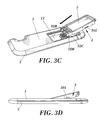
- the cartridge in order to insert the cartridge 3 into the body structure of the sun visor, the cartridge is inclined (as illustrated in figure 3B ) and inserted, with the extending portion 32A first ( figures 3C and 3D ), until it abuts against a corresponding edge of the opening 11 (as shown in figure 3E ). Then, the cartridge is pressed downwards ( figure 3E ), pivoting around its front part, until the clips 21 and 22 of the rear shell 2 snap into the corresponding openings 301, 302 in the walls of the cartridge.
- the frame 33 of the cartridge remains outside the shells, abutting against the outer surface of the front shell 1, as shown in figure 3F .
- the cartridge serves as a further interconnection or interlocking of the front and rear shells.
- a user can move the cover longitudinally towards its open position; a rib 52 is provided on the outer surface of the cover 5 so as to facilitate movement of the cover by the user.
- Figure 6 schematically illustrates a top view of the sun visor, with the front shell cut away and the cover in its open position. It can be observed how the extending guide rails 32B provide support for the cover also in its open position, wherefore no guide rails for the cover are needed in the shells.
- the distance (corresponding to 32A) by which the guide rails extend from the main portion of the cartridge can be readily chosen by the skilled person. However, it can be convenient to choose said extension so that support surfaces 32 are provided that, when the cover is in its closed position, extend a distance X beyond the corresponding longitudinal edge 51 of the cover, X being at least 10% of the length of said longitudinal edge 51.
- FIGs 4 and 5 schematically illustrate the rear shell connected to a supporting arm 6 of the sun visor, a conventional spring means 7 being provided so as to make it possible to selectively set the sun visor in a plurality of positions, pivoting it around the arm 6.
- the clips 21 and 22 for snap connection of the cartridge can be observed.
- Figures 7A-7C illustrate different views of the sun visor, further illustrating the components and connections discussed further above.
- Figure 8 schematically illustrates how the front shell 1 comprises one single body obtained by injection moulding, whereas the rear shell comprises a shell part 2A and a reinforcing grid part 2B, both obtained or obtainable in separate injection moulding steps, whereby said shell part 2A and grid part 2B can be interconnected to form the rear shell.
- the grid part can comprise the different coupling clips 21 and 22 of the rear shell, arranged to interact with coupling means of the cartridge.
Abstract
Description
- The invention relates to the field of sun visors useful for motor vehicles.
- In motor vehicles, sun visors are often provided in order to protect the driver from incoming sunlight. Often, a sun visor is also provided for the passenger sitting next to the driver. These sun visors are normally provided on a (substantially horizontal) shaft or similar so that they can be pivoted between a "non-operative" position (in which they do not protect the driver from incoming sunlight) and one or more "operative" positions, in which they prevent or substantially prevent the incoming light from arriving directly at the driver's (or passenger's) eyes. Also, often, the shaft can also be pivoted between a position in which it extends substantially parallel with the windscreen of the vehicle, and a position substantially aligned with a side window of the vehicle.
- Often, these sun visors incorporate a mirror (sometimes referred to as a "vanity mirror") and a cover for the mirror. The cover can often be slid from a closed position (in which it covers the mirror) and an open position (in which it does not cover the mirror or, at least, leaves a substantial part of the mirror uncovered).
- There exist at least two different basic technologies for producing this type of sun visors.
- A first one of these technologies corresponds to sun visors based on one single moulded grid (made in some kind of plastic material), onto each major surface of which an external part comprising foam is applied. The assembly is then covered with some kind of cover, such as a textile cover. The external foam part can be made up of -or be based on- polyurethane, expanded polyethylene, etc.
- In this kind of sun visors, the only structural member is the grid. Thus, the means for attaching or holding the mirror, as well as the means for holding the cover and for guiding it in its movement between its closed and its open position, are all embodied in the plastic grid part.
-
FR-A-2788730 - An alternative sun visor technology is based on the use of two shells, normally of some kind of plastic material, normally obtained by injection moulding. These two shells constitute, when assembled together, the structural element of the sun visor. Further, some kind of cover or lining is normally applied, as well as additional elements, such as the vanity mirror and its cover.
- In this kind of "twin shell" sun visors, the means for holding the mirror and for guiding and holding the cover are conventionally established partly by one of the shells and partly by the other shell, so that it is the combination of the shells, when assembled together, that establishes the complete set of means (such as guide rails with guide grooves) for guiding and holding these elements in place. Now, this implies a rather complex assembly process, as the mirror and/or the cover will not be held appropriately in place until both shells have been assembled together. For example, the mirror and the cover can be placed on a first one of the shells, and then the other shell can be applied over said first shell, so that, once both shells have been duly interconnected, the mirror and the cover are trapped between the shells, with the longitudinal ends of the cover held within guide grooves along which the cover can slide.
- In order to facilitate the process of assembly, an alternative "twin shell" technique involves the use of a mirror cartridge that, at some state of the assembly process, is coupled to the shells. This mirror cartridge holds the mirror and the cover and thus overcomes the difficulties involved with incorporating the mirror and the cover between the shells during the assembly process. One of the shells includes additional guide rails for guiding the cover in its movement between the open and the closed position, and said guide rails must be correctly positioned and aligned with respect to the cartridge. Also, there is normally a "snapping" noise when the cover is displaced between its closed and open position, caused by the transfer of the leading or trailing edge of the cover between the guide rails of the cartridge and the guide rails of the shell. Also, the guide rails normally have a "U" shape that makes it more difficult to obtain the shells by moulding, as the withdrawal of the moulded elements from the mould becomes a more complex issue.
-
DE-U-20217313 discloses a prior art twin shell structure with a cartridge for the mirror and the cover, wherein the upper shell is provided with guide rails for the cover.WO-A-2006/064027 discloses another example of a twin shell sun visor structure with a cartridge for holding the mirror and the cover, and wherein a single guide rail for guiding the cover is provided in the lower shell. -
JP-A-10-315764 - A first aspect of the invention relates to a sun visor assembly comprising:
- a front shell having an opening (a mirror opening, for allowing a user to view a mirror) and a rear shell, said front and rear shells being arranged to be coupled together and comprising connection means (that is, clips and/or other means for attaching the two shells to each other, such as contact surfaces to be welded together, etc.) for keeping said front and rear shells coupled together once they have been assembled to each other, so as to constitute a sun visor body structure. That is, the sun visor is basically a "twin shell" type sun visor.
- Further, the assembly comprises a cartridge housing a mirror and a cover for the mirror. The cartridge comprises mirror holding means for holding the mirror, so that it cannot move or at least so that it is substantially immobilised, and guide means for guiding the cover so that the cover can slide between an open position in which it does not substantially cover the mirror (that is, in which it leaves the mirror uncovered so that it can be seen through the opening in the front shell), and a closed position in which it substantially covers the mirror (so that the user cannot view it from outside the sun visor).
- The cover has two longitudinal edges, and the guide means establish, for each longitudinal edge, at least one longitudinal support surface over which the cover can slide when moving between its closed position and its open position.
- The longitudinal support surface can be continuous or not, that is, it can be a continuous surface that is present all along the total extension of the support surface (that is, from one end to the other), or it can be interrupted at one or more occasions along its extension.
- According to the invention, when the cover is in its closed position, said at least one support surface extends longitudinally substantially beyond the corresponding longitudinal edge of the cover, so as to provide support to said longitudinal edge when the cover is displaced towards its open position.
- Thus, the cartridge itself provides a longitudinally extended support surface, for example, longitudinally extended guide rails, thus making it unnecessary to establish guide rails or other support surfaces in the front or rear shells. This substantially simplifies the production of the shells (such as the moulding process), as well as the assembly process, as no alignment between guide rails in the cartridge and guide rails in the shells is necessary. Also, the operation of the cover becomes more reliable, as it does not need to slide between guide rails associated to different parts or elements of the assembly.
- The shells as well as the cartridge can be made up of single, moulded, plastic elements.
- The cartridge can be assembled after finishing of the sun visor, that is, after assembly of, for example, a covering surface material like PVC or a fabric and after assembly of other components, such as an articulation or holding arm, or similar.
- The at least one support surface can extend longitudinally a distance X beyond the corresponding longitudinal edge of the cover when the cover is in the closed position, X being equal to or larger than 10% (or 20%, or 30%, or 40%, or 50%, or even 75% ) of the length of said longitudinal edge. Sometimes, it may be preferable that the support surface not extend to far, in which case X can be less than, for example, 50% of the length of said longitudinal edge. Basically, it is normally enough if the support surface supports the cover (in the longitudinal direction) along a portion of each of its longitudinal edges when the cover is in its open position, such as along 10%, or 20%, or 30%, or 40% of its longitudinal edges. A shorter extended support surface can simplify the assembly process.
- The at least one support surface can have a length (in the longitudinal direction)of at least 125% (or even at least 150%) of the length of the corresponding longitudinal edge.
- The selection of a suitable length or extension of the support surface can easily be made by the skilled person, in view of the other design conditions that must be considered in each specific case.
- Thus, it can be preferred that none of said front shell and rear shell comprises guide rails and/or guide grooves for guiding the cover when moving between its open and its closed position.
- The cartridge can further comprise a frame part arranged to abut against an outer surface of said front shell, so as to cover the edges of the opening and further to block the front shell in its position. The support surfaces can extend longitudinally beyond the orthogonal projection of the frame, that is, when viewed from above, these support surfaces can extend beyond the perimeter of the frame and, thus, also beyond the perimeter of the opening. For example, the support surfaces can extend longitudinally a distance Y beyond the orthogonal projection of the frame, Y being, for example, at least 15% of the length of the cover or even at least 25% of the length of the cover.
- For example, the entire cartridge (including the extension represented by the support surfaces) can have a length at least 15% (or at least 25%) longer than the length of the opening.
- The rear shell can comprise coupling means (such as clips and/or openings and/or recesses) complementary to coupling means (such as openings and/or recesses and/or clips) provided on the cartridge, so as to lock the cartridge to the rear shell (for example, by snap connection) when assembled.
- The cartridge has a body portion dimensioned to be inserted through the opening in the front shell, said body portion including at least a part of said guide means for the cover.
- At least a part of the guide means can be arranged to define a guide channel dimensioned to house a corresponding longitudinal edge of the cover, said guide means abutting against opposite surfaces of the cover along said guide channel.
- The cartridge can be provided with at least one flexible element arranged to abut against a rear surface of the cover, so as to contribute to a control of the force necessary to move the cover longitudinally, and so as to reduce the tendency of "flapping" of the cover.
- The cover can further be provided with at least two position defining elements, such as transversal projections or recesses, arranged to interact with said at least one flexible element when the cover passes from its closed position to its open position, so as to provide for a snap interaction between a first one of said position defining elements and said flexible element when the cover substantially reaches its open position, and a snap interaction between a second one of said position defining elements and said flexible element when the cover substantially reaches its closed position. Thus, a clear "snap definition" of said open and closed positions is obtained, at a force exceeding a certain threshold is needed to move the cover from any of said positions, thus contributing to avoiding the risk for "accidental opening" or "closing" of the cover.
- The rear shell can comprise one single element, directly obtained as such, as a single piece, by injection moulding. However, in accordance with an alternative implementation of the invention, the rear shell can comprise a shell part and a reinforcing grid part, both obtained in separate steps of injection moulding, whereby the grid part can be placed in the shell part so as to constitute, together with the shell part, the rear shell. If so, the different coupling means of the rear shell arranged to interact with coupling means of the cartridge can be embodied in said grid part. The grid part can comprise means for connecting it to the shell part of the rear shell and/or to the front shell. Thus, these three parts can be preassembled, and subsequently the cartridge can be assembled to the interconnected shells.
- A further aspect of the invention relates to a sun visor, comprising a sun visor assembly as described above, with the front shell and rear shell interconnected and the cartridge mounted (except the frame, when there is such a frame; the frame can abut against the outer surface of the front shell) between said front and rear shells, the cover being accessible through the opening (or, at least, in correspondence with the opening) in the front shell.
- A further aspect of the invention relates to a method of assembling a sun visor out of a sun visor assembly as described above, comprising the steps of
- interconnecting the front shell and the rear shell;
- inserting a longitudinally projecting portion of the guide means for the cover through the opening in the front shell (for example, by movement in a first direction, that can be inclined although substantially parallel with regard to the shells; the projecting portion corresponds to at least a part of the longitudinal extension of the support surfaces, as describe above, that is, of the longitudinal extension extending beyond the longitudinal edges of the cover when the cover is in its closed position);
- subsequently, inserting a main portion of the cartridge through said opening until it becomes coupled to the rear shell (this can be done by, basically, pushing the body of the cartridge against the rear shell, thus pivoting the cartridge around its front part).
- The main portion of the cartridge can in that way become coupled to the rear shell by snap connection. When the cartridge has a frame, this frame can abut against the outer surface of the front shell, covering the edges of the opening in the front shell. Thus, the cartridge will help to interlock the front and rear shells.
- To complete the description and in order to provide for a better understanding of the invention, a set of drawings is provided. Said drawings form an integral part of the description and illustrate a preferred embodiment of the invention, which should not be interpreted as restricting the scope of the invention, but just as an example of how the invention can be embodied. The drawings comprise the following figures:
-
Figure 1 .- Shows an exploded perspective view of a cartridge of an assembly in accordance with a preferred embodiment of the invention. -
Figures 2A and 2B .- Show a perspective view of the cartridge, with the cover in its open and in its closed position, respectively. -
Figures 3A-3F .- Schematically illustrate how the cartridge can be assembled to the shells, in accordance with a preferred embodiment of the invention. -
Figures 4 and5 .- Show partial perspective views of the rear shell. -
Figure 6 .- Illustrates a top view of the assembly in accordance with said preferred embodiment of the invention, with the front shell cut away. -
Figures 7A-7C .- Show a top view, a transversal cross section and a longitudinal cross section of the sun visor, respectively. -
Figure 8 .- Schematically illustrates a possible embodiment of the front and rear shells. -
Figure 1 illustrates acartridge 3, into which acover 5, amirror 4 and a plastic plate with adhesive 41, that covers a rear face of the mirror 4 (and that serves to retain broken pieces of the mirror after a crash impact, as known in the state of art), when the assembly is in its assembled state. The cover can be inserted into thecartridge 3 to rest on asupport surface 32, and afterwards the mirror 4 (with the adhesive plate 41) is inserted and held in place byclips 31 or other suitable means for retaining the mirror within the cartridge.Front 34 and rear 35 transversal walls delimit the space within the cartridge, and the mirror will be prevented from moving by thelongitudinal side walls 36, theclips 31, therear wall 35, alongitudinal support surface 37 and a pair ofstops 38, all of which represent support surfaces for the mirror against which the mirror abuts, so as to be held firmly in place. - However, the cover, also trapped between the
side walls 36, therear wall 35, the mirror and thecover support surface 32, can move longitudinally, between a closed position (in which it covers the mirror so that it cannot be observed from outside when the sun visor is in use) and an open position, in which it leaves a major part of the mirror uncovered, so that it can be seen from outside. - Apart from the "box" or "body portion" defined by the
side walls 36, thefront wall 34 and therear wall 35, the cartridge comprises aframe 33 and an extending or projectingportion 32A, arranged so as to provide an extended portion of thesupport surface 32 which will support thecover 5 when displaced towards its open position. Thus, the support surface will at least partly support the correspondinglongitudinal edges 51 of thecover 5, also when it is in its maximally open position. - The
side walls 36 and therear wall 35 are provided withopenings spring element 303 is provided that exerts a certain elastic force on the rear surface of the cover, so as to reduce the risk for noise due to "flapping" of the cover, especially when it is in its open position. - Also, in order to more reliably maintain the cover in its open and closed position, respectively, the rear surface of the cover is provided with two protruding
portions spring element 303 when the cover is in its closed position, so that it will have to pass the spring element and deflect it when the cover passes towards its open position. The other protrudingportion 304 will be positioned just passed thespring element 303 when the cover is in its open position, so that it will have to pass the spring element, deflecting it, when the cover is moved from the open position towards the closed position. Thus, the interaction between these two protrudingportions spring element 303 will cause a "snap" interaction between the spring element and thecover 5, in correspondence with the open and closed positions of the cover, respectively. -
Figures 2A and 2B illustrate the cartridge with the cover in its open position (leaving themirror 4 uncovered) and in its closed position, respectively.Guide rails 32B extend from the main body or portion of the cartridge, defining the corresponding support surfaces for thelongitudinal edges 51 of the cartridge. Infigure 2A it can be observed how theseguide rails 32B provide support for part of the cover even in the maximum open position of the cover. -
Figure 3A-3F schematically illustrate how the cartridge is to be assembled to the sun visor shells. Afront shell 1 and arear shell 2 are interconnected (for example, byconventional clips 201 as illustrated infigure 6 and/or by other conventional connection means, such as other kinds of snap connection, welding, etc.), thus making up a body structure of the sun visor. -
Figure 3A is a perspective view of said body structure, comprising saidfront shell 1 andrear shell 2. The front shell comprises anopening 11 having a substantially rectangular shape, the length of said opening substantially corresponding to thelength 3A of the main body or portion of the cartridge, not including theextension 32A. Within the opening, theclips rear shell 2, used for retaining the cartridge, are schematically illustrated. - Thus, in order to insert the
cartridge 3 into the body structure of the sun visor, the cartridge is inclined (as illustrated infigure 3B ) and inserted, with the extendingportion 32A first (figures 3C and 3D ), until it abuts against a corresponding edge of the opening 11 (as shown infigure 3E ). Then, the cartridge is pressed downwards (figure 3E ), pivoting around its front part, until theclips rear shell 2 snap into the correspondingopenings frame 33 of the cartridge remains outside the shells, abutting against the outer surface of thefront shell 1, as shown infigure 3F . Thus, the cartridge serves as a further interconnection or interlocking of the front and rear shells. Now, a user can move the cover longitudinally towards its open position; arib 52 is provided on the outer surface of thecover 5 so as to facilitate movement of the cover by the user. -
Figure 6 schematically illustrates a top view of the sun visor, with the front shell cut away and the cover in its open position. It can be observed how the extendingguide rails 32B provide support for the cover also in its open position, wherefore no guide rails for the cover are needed in the shells. The distance (corresponding to 32A) by which the guide rails extend from the main portion of the cartridge can be readily chosen by the skilled person. However, it can be convenient to choose said extension so that support surfaces 32 are provided that, when the cover is in its closed position, extend a distance X beyond the correspondinglongitudinal edge 51 of the cover, X being at least 10% of the length of saidlongitudinal edge 51. The longer this distance X, the better the support provided, but, on the other hand, a long extending portion of the cartridge will also make the assembly process more complicated (as can be readily understood fromfigures 3A-3F ) and imply more restrictions on the design of the shells. The skilled person will easily be able to choose the correct dimension for each specific assembly design. In the drawings (for example,figures 3A-3C ) it can, for example, be observed how thecartridge 3, in correspondence with the extendingportion 32A, is provided with aninclined surface 32C, so as to reduce the risk for interaction between that part of the cartridge and the rear shell, during assembly. -
Figures 4 and5 schematically illustrate the rear shell connected to a supportingarm 6 of the sun visor, a conventional spring means 7 being provided so as to make it possible to selectively set the sun visor in a plurality of positions, pivoting it around thearm 6. Infigures 4 and5 , theclips -
Figures 7A-7C illustrate different views of the sun visor, further illustrating the components and connections discussed further above. -
Figure 8 schematically illustrates how thefront shell 1 comprises one single body obtained by injection moulding, whereas the rear shell comprises ashell part 2A and a reinforcinggrid part 2B, both obtained or obtainable in separate injection moulding steps, whereby saidshell part 2A andgrid part 2B can be interconnected to form the rear shell. The grid part can comprise thedifferent coupling clips - In this text, the term "comprises" and its derivations (such as "comprising", etc.) should not be understood in an excluding sense, that is, these terms should not be interpreted as excluding the possibility that what is described and defined may include further elements, steps, etc.
- On the other hand, the invention is obviously not limited to the specific embodiment(s) described herein, but also encompasses any variations that may be considered by any person skilled in the art (for example, as regards the choice of materials, dimensions, components, configuration, etc.), within the general scope of the invention as defined in the claims.
Claims (27)
- Sun visor assembly comprising
a front shell (1) having a mirror opening (11), and a rear shell (2), the front shell and the rear shell being arranged to be coupled together and comprising connection means (201) for keeping said front and rear shells coupled together once they have been assembled to each other, so as to constitute a sun visor body structure, and
a cartridge (3) housing a mirror (4) and a cover (5), said cartridge comprising mirror holding means (31) for holding the mirror and guide means for guiding the cover (5) so that the cover can slide between an open position in which it does not substantially cover the mirror, and a closed position in which it substantially covers the mirror, said cover having two longitudinal edges (51), said guide means establishing, for each longitudinal edge, at least one longitudinal support surface (32) over which the cover can slide when moving between its closed position and its open position;
characterised in that
when the cover is in its closed position, said at least one support surface extends longitudinally substantially beyond the corresponding longitudinal edge (51) of the cover, so as to provide support to said longitudinal edge when the cover is displaced towards its open position. - Sun visor assembly according to claim 1, wherein said at least one support surface (32) extends longitudinally a distance X beyond the corresponding longitudinal edge (51) of the cover when the cover is in the closed position, X being equal to or larger than 10% of the length of said longitudinal edge (51).
- Sun visor assembly according to claim 2, wherein X is equal to or larger than 20% of the length of said longitudinal edge (51).
- Sun visor assembly according to claim 2, wherein X is equal to or larger than 30% of the length of said longitudinal edge (51).
- Sun visor assembly according to claim 2, wherein X is equal to or larger than 40% of the length of said longitudinal edge (51).
- Sun visor assembly according to claim 2, wherein X is equal to or larger than 50% of the length of said longitudinal edge (51).
- Sun visor assembly according to claim 2, wherein X is equal to or larger than 75% of the length of said longitudinal edge (51).
- Sun visor assembly according to any of claims 2-5, wherein X is less than 50% of the length of said longitudinal edge (51).
- Sun visor assembly according to claim 1, wherein said at least one support surface (32) has a length of at least 125% of the length of the corresponding longitudinal edge (51).
- Sun visor assembly according to claim 1, wherein said at least one support surface (32) has a length of at least 150% of the length of the corresponding longitudinal edge (51).
- Sun visor assembly according to any of the preceding claims, wherein none of said front shell (1) and rear shell (2) comprises guide rails for guiding said cover when moving between its open and its closed position.
- Sun visor assembly according to any of the preceding claims, wherein said cartridge comprises a frame part (33) arranged to abut against an outer surface of said front shell (1).
- Sun visor assembly according to claim 12, wherein said at least one support surface (32) extends longitudinally beyond the orthogonal projection of the frame.
- Sun visor assembly according to claim 13, wherein said at least one support surface (32) extends longitudinally a distance Y beyond the orthogonal projection of the frame, Y being at least 15% of the length of the cover.
- Sun visor assembly according to claim 14, wherein Y is at least 25% of the length of the cover.
- Sun visor assembly according to any of the preceding claims, wherein the cartridge (3) has a length at least 15% longer than the length of the opening (11).
- Sun visor assembly according to any of the preceding claims, wherein the cartridge (3) has a length at least 25% longer than the length of the opening (11).
- Sun visor assembly according to any of the preceding claims, wherein said second shell (2) comprises coupling means (21, 22) arranged to interact with coupling means (301, 302) on the cartridge, so as to lock the cartridge (3) to the second shell (1) when assembled.
- Sun visor assembly according to any of the preceding claims, wherein the cartridge has a body portion dimensioned to be inserted through the opening (11) in the front shell (1), said body portion including said guide means for the cover.
- Sun visor assembly according to any of the preceding claims, wherein at least a part of said guide means (32B) are arranged to define a guide channel dimensioned to house a corresponding longitudinal edge of the cover, said guide means abutting against opposite surfaces of the cover along said guide channel.
- Sun visor assembly according to any of the preceding claims, wherein said cartridge is provided with at least one flexible element (303) arranged to abut against a rear surface of the cover (5).
- Sun visor assembly according to claim 20, wherein said cover (5) is provided with at least two position defining elements (304, 305) arranged to interact with said at least one flexible element (303) when the cover passes from its closed position to its open position, so as to provide for a snap interaction between a first one (304) of said position defining elements and said flexible element (303) when the cover substantially reaches its open position, and a snap interaction between a second one (305) of said position defining elements and said flexible element (303) when the cover substantially reaches its closed position.
- Sun visor assembly according to any of the preceding claims, wherein the rear shell (2) comprises one single element, directly obtained as one single piece by injection moulding.
- Sun visor assembly according to claim 18, wherein the rear shell comprises a shell part (2A) and a reinforcing grid part (2B), both obtained in separate steps of injection moulding, wherein coupling means (21, 22) of the rear shell arranged to interact with coupling means of the cartridge are embodied in said grid part (2B).
- Sun visor, comprising a sun visor assembly according to any of the preceding claims, with the front shell (1) and rear shell (2) interconnected and the cartridge mounted between said front and rear shells, the cover being accessible through the opening (11) in the front shell (1).
- Method of assembling a sun visor out of a sun visor assembly according to any of claims 1-24, comprising the steps of- interconnecting the front shell (1) and the rear shell (2);- inserting a projecting portion (32A) of the guide means for the cover through the opening (11) in the front shell (1);- subsequently, inserting a main portion of the cartridge (3) through said opening until it becomes coupled to the rear shell (2).
- Method according to claim 26, wherein said main portion of the cartridge (3) becomes coupled to the rear shell by snap connection.
Priority Applications (4)
| Application Number | Priority Date | Filing Date | Title |
|---|---|---|---|
| AT07007499T ATE470588T1 (en) | 2007-04-12 | 2007-04-12 | SUN VISOR CONSTRUCTION, SUN VISOR AND INSTALLATION METHOD THEREOF |
| DE602007007051T DE602007007051D1 (en) | 2007-04-12 | 2007-04-12 | Sun visor construction, sun visor and mounting method therefor |
| EP07007499A EP1980435B1 (en) | 2007-04-12 | 2007-04-12 | Sun visor assembly, sun visor and method of assembling it |
| ES07007499T ES2349859T3 (en) | 2007-04-12 | 2007-04-12 | SET OF PARASOL, PARASOL AND PROCEDURE FOR USE. |
Applications Claiming Priority (1)
| Application Number | Priority Date | Filing Date | Title |
|---|---|---|---|
| EP07007499A EP1980435B1 (en) | 2007-04-12 | 2007-04-12 | Sun visor assembly, sun visor and method of assembling it |
Publications (2)
| Publication Number | Publication Date |
|---|---|
| EP1980435A1 true EP1980435A1 (en) | 2008-10-15 |
| EP1980435B1 EP1980435B1 (en) | 2010-06-09 |
Family
ID=38515730
Family Applications (1)
| Application Number | Title | Priority Date | Filing Date |
|---|---|---|---|
| EP07007499A Revoked EP1980435B1 (en) | 2007-04-12 | 2007-04-12 | Sun visor assembly, sun visor and method of assembling it |
Country Status (4)
| Country | Link |
|---|---|
| EP (1) | EP1980435B1 (en) |
| AT (1) | ATE470588T1 (en) |
| DE (1) | DE602007007051D1 (en) |
| ES (1) | ES2349859T3 (en) |
Cited By (3)
| Publication number | Priority date | Publication date | Assignee | Title |
|---|---|---|---|---|
| WO2012013340A1 (en) * | 2010-07-27 | 2012-02-02 | Johnson Controls Interiors Gmbh & Co. Kg | Sunshade and method for mounting same |
| WO2019044936A1 (en) * | 2017-09-01 | 2019-03-07 | 共和産業株式会社 | Mirror unit |
| WO2019044935A1 (en) * | 2017-09-01 | 2019-03-07 | 共和産業株式会社 | Sunvisor for vehicle |
Citations (5)
| Publication number | Priority date | Publication date | Assignee | Title |
|---|---|---|---|---|
| EP0655359A1 (en) * | 1993-11-30 | 1995-05-31 | GEBR. HAPPICH GmbH | Sun visor for vehicles |
| JPH10315764A (en) * | 1997-05-19 | 1998-12-02 | Kasai Kogyo Co Ltd | Sunvisor with mirror unit |
| FR2788730A1 (en) * | 1999-01-26 | 2000-07-28 | Meritor Lvs France | Sunshade with built-in mirror for use in vehicle has cover for mirror and plastics covering foils on front and rear of assembly |
| DE20217313U1 (en) * | 2002-11-07 | 2004-03-18 | Johnson Controls Interiors Gmbh & Co. Kg | Glare shield for a motor vehicle comprises a body consisting of two joinable shells, with one shell provided with interior guide elements for a slidable lid serving as a mirror cover |
| WO2006064027A1 (en) * | 2004-12-15 | 2006-06-22 | Johnson Controls Interiors Gmbh & Co. Kg | Mirror module, especially for a vehicle, component comprising said mirror module, especially a sun visor and especially for a vehicle, method for assembling the component, and use of the component as a sun visor in a motor vehicle |
-
2007
- 2007-04-12 AT AT07007499T patent/ATE470588T1/en not_active IP Right Cessation
- 2007-04-12 EP EP07007499A patent/EP1980435B1/en not_active Revoked
- 2007-04-12 DE DE602007007051T patent/DE602007007051D1/en active Active
- 2007-04-12 ES ES07007499T patent/ES2349859T3/en active Active
Patent Citations (5)
| Publication number | Priority date | Publication date | Assignee | Title |
|---|---|---|---|---|
| EP0655359A1 (en) * | 1993-11-30 | 1995-05-31 | GEBR. HAPPICH GmbH | Sun visor for vehicles |
| JPH10315764A (en) * | 1997-05-19 | 1998-12-02 | Kasai Kogyo Co Ltd | Sunvisor with mirror unit |
| FR2788730A1 (en) * | 1999-01-26 | 2000-07-28 | Meritor Lvs France | Sunshade with built-in mirror for use in vehicle has cover for mirror and plastics covering foils on front and rear of assembly |
| DE20217313U1 (en) * | 2002-11-07 | 2004-03-18 | Johnson Controls Interiors Gmbh & Co. Kg | Glare shield for a motor vehicle comprises a body consisting of two joinable shells, with one shell provided with interior guide elements for a slidable lid serving as a mirror cover |
| WO2006064027A1 (en) * | 2004-12-15 | 2006-06-22 | Johnson Controls Interiors Gmbh & Co. Kg | Mirror module, especially for a vehicle, component comprising said mirror module, especially a sun visor and especially for a vehicle, method for assembling the component, and use of the component as a sun visor in a motor vehicle |
Cited By (4)
| Publication number | Priority date | Publication date | Assignee | Title |
|---|---|---|---|---|
| WO2012013340A1 (en) * | 2010-07-27 | 2012-02-02 | Johnson Controls Interiors Gmbh & Co. Kg | Sunshade and method for mounting same |
| WO2019044936A1 (en) * | 2017-09-01 | 2019-03-07 | 共和産業株式会社 | Mirror unit |
| WO2019044935A1 (en) * | 2017-09-01 | 2019-03-07 | 共和産業株式会社 | Sunvisor for vehicle |
| JP2019043367A (en) * | 2017-09-01 | 2019-03-22 | 共和産業株式会社 | Mirror unit |
Also Published As
| Publication number | Publication date |
|---|---|
| EP1980435B1 (en) | 2010-06-09 |
| ES2349859T3 (en) | 2011-01-12 |
| ATE470588T1 (en) | 2010-06-15 |
| DE602007007051D1 (en) | 2010-07-22 |
Similar Documents
| Publication | Publication Date | Title |
|---|---|---|
| JP4797091B2 (en) | Shade panel interlocking mechanism in sunroof equipment | |
| KR101595715B1 (en) | Channel for slide-on-rod visors | |
| EP2145789B1 (en) | Vehicle-mountable sun visor | |
| US4910918A (en) | Corner structure for glass run channel | |
| JP4704067B2 (en) | Vehicle glass guide structure | |
| CN102753053A (en) | Compact container with built-in hinge unit and method for manufacturing compact container with built-in hinge unit | |
| GB2315513A (en) | Motor vehicle windows | |
| EP2415624B1 (en) | Deflector apparatus for vehicle | |
| EP1980435B1 (en) | Sun visor assembly, sun visor and method of assembling it | |
| CN101628537B (en) | Vehicle-mountable sun visor | |
| EP1698500B1 (en) | Sun visor assembly | |
| JPH0822652B2 (en) | Support device | |
| EP2070751B1 (en) | Power back door for vehicle | |
| US8740282B2 (en) | Vehicular sun visor | |
| US4722565A (en) | Tilt-slide type sunroof of motor vehicle | |
| US7909383B2 (en) | Mirror module for vehicle component and method of assembling a mirror module | |
| CN107848382B (en) | Wind deflector with fastening system for deployable guide elements | |
| US11858325B2 (en) | Deflector mechanism of sunroof device | |
| CN109849634A (en) | Water cut end head mounting structure and vehicle | |
| EP1958808B1 (en) | Sun visor assembly, sun visor and method of assembling it | |
| CN214564538U (en) | Sealing member and sunroof device | |
| CN209756769U (en) | Wind screen mechanism for automobile skylight and automobile skylight assembly | |
| US8800635B2 (en) | Lateral guide for shading roller blind, and shading roller blind for motor vehicles | |
| US20130020838A1 (en) | Roof apparatus for vehicle | |
| JP4271786B2 (en) | Sunroof deflector structure |
Legal Events
| Date | Code | Title | Description |
|---|---|---|---|
| PUAI | Public reference made under article 153(3) epc to a published international application that has entered the european phase |
Free format text: ORIGINAL CODE: 0009012 |
|
| AK | Designated contracting states |
Kind code of ref document: A1 Designated state(s): AT BE BG CH CY CZ DE DK EE ES FI FR GB GR HU IE IS IT LI LT LU LV MC MT NL PL PT RO SE SI SK TR |
|
| AX | Request for extension of the european patent |
Extension state: AL BA HR MK RS |
|
| 17P | Request for examination filed |
Effective date: 20090403 |
|
| AKX | Designation fees paid |
Designated state(s): AT BE BG CH CY CZ DE DK EE ES FI FR GB GR HU IE IS IT LI LT LU LV MC MT NL PL PT RO SE SI SK TR |
|
| GRAP | Despatch of communication of intention to grant a patent |
Free format text: ORIGINAL CODE: EPIDOSNIGR1 |
|
| GRAS | Grant fee paid |
Free format text: ORIGINAL CODE: EPIDOSNIGR3 |
|
| GRAA | (expected) grant |
Free format text: ORIGINAL CODE: 0009210 |
|
| AK | Designated contracting states |
Kind code of ref document: B1 Designated state(s): AT BE BG CH CY CZ DE DK EE ES FI FR GB GR HU IE IS IT LI LT LU LV MC MT NL PL PT RO SE SI SK TR |
|
| REG | Reference to a national code |
Ref country code: CH Ref legal event code: EP |
|
| REG | Reference to a national code |
Ref country code: IE Ref legal event code: FG4D |
|
| REF | Corresponds to: |
Ref document number: 602007007051 Country of ref document: DE Date of ref document: 20100722 Kind code of ref document: P |
|
| REG | Reference to a national code |
Ref country code: NL Ref legal event code: VDEP Effective date: 20100609 |
|
| PG25 | Lapsed in a contracting state [announced via postgrant information from national office to epo] |
Ref country code: SE Free format text: LAPSE BECAUSE OF FAILURE TO SUBMIT A TRANSLATION OF THE DESCRIPTION OR TO PAY THE FEE WITHIN THE PRESCRIBED TIME-LIMIT Effective date: 20100609 Ref country code: LT Free format text: LAPSE BECAUSE OF FAILURE TO SUBMIT A TRANSLATION OF THE DESCRIPTION OR TO PAY THE FEE WITHIN THE PRESCRIBED TIME-LIMIT Effective date: 20100609 |
|
| LTIE | Lt: invalidation of european patent or patent extension |
Effective date: 20100609 |
|
| PG25 | Lapsed in a contracting state [announced via postgrant information from national office to epo] |
Ref country code: SI Free format text: LAPSE BECAUSE OF FAILURE TO SUBMIT A TRANSLATION OF THE DESCRIPTION OR TO PAY THE FEE WITHIN THE PRESCRIBED TIME-LIMIT Effective date: 20100609 Ref country code: AT Free format text: LAPSE BECAUSE OF FAILURE TO SUBMIT A TRANSLATION OF THE DESCRIPTION OR TO PAY THE FEE WITHIN THE PRESCRIBED TIME-LIMIT Effective date: 20100609 Ref country code: FI Free format text: LAPSE BECAUSE OF FAILURE TO SUBMIT A TRANSLATION OF THE DESCRIPTION OR TO PAY THE FEE WITHIN THE PRESCRIBED TIME-LIMIT Effective date: 20100609 Ref country code: LV Free format text: LAPSE BECAUSE OF FAILURE TO SUBMIT A TRANSLATION OF THE DESCRIPTION OR TO PAY THE FEE WITHIN THE PRESCRIBED TIME-LIMIT Effective date: 20100609 |
|
| PG25 | Lapsed in a contracting state [announced via postgrant information from national office to epo] |
Ref country code: CY Free format text: LAPSE BECAUSE OF FAILURE TO SUBMIT A TRANSLATION OF THE DESCRIPTION OR TO PAY THE FEE WITHIN THE PRESCRIBED TIME-LIMIT Effective date: 20100609 Ref country code: PL Free format text: LAPSE BECAUSE OF FAILURE TO SUBMIT A TRANSLATION OF THE DESCRIPTION OR TO PAY THE FEE WITHIN THE PRESCRIBED TIME-LIMIT Effective date: 20100609 |
|
| REG | Reference to a national code |
Ref country code: ES Ref legal event code: FG2A Effective date: 20101229 |
|
| PG25 | Lapsed in a contracting state [announced via postgrant information from national office to epo] |
Ref country code: EE Free format text: LAPSE BECAUSE OF FAILURE TO SUBMIT A TRANSLATION OF THE DESCRIPTION OR TO PAY THE FEE WITHIN THE PRESCRIBED TIME-LIMIT Effective date: 20100609 Ref country code: GR Free format text: LAPSE BECAUSE OF FAILURE TO SUBMIT A TRANSLATION OF THE DESCRIPTION OR TO PAY THE FEE WITHIN THE PRESCRIBED TIME-LIMIT Effective date: 20100910 Ref country code: NL Free format text: LAPSE BECAUSE OF FAILURE TO SUBMIT A TRANSLATION OF THE DESCRIPTION OR TO PAY THE FEE WITHIN THE PRESCRIBED TIME-LIMIT Effective date: 20100609 |
|
| PG25 | Lapsed in a contracting state [announced via postgrant information from national office to epo] |
Ref country code: RO Free format text: LAPSE BECAUSE OF FAILURE TO SUBMIT A TRANSLATION OF THE DESCRIPTION OR TO PAY THE FEE WITHIN THE PRESCRIBED TIME-LIMIT Effective date: 20100609 Ref country code: IS Free format text: LAPSE BECAUSE OF FAILURE TO SUBMIT A TRANSLATION OF THE DESCRIPTION OR TO PAY THE FEE WITHIN THE PRESCRIBED TIME-LIMIT Effective date: 20101009 Ref country code: CZ Free format text: LAPSE BECAUSE OF FAILURE TO SUBMIT A TRANSLATION OF THE DESCRIPTION OR TO PAY THE FEE WITHIN THE PRESCRIBED TIME-LIMIT Effective date: 20100609 Ref country code: BE Free format text: LAPSE BECAUSE OF FAILURE TO SUBMIT A TRANSLATION OF THE DESCRIPTION OR TO PAY THE FEE WITHIN THE PRESCRIBED TIME-LIMIT Effective date: 20100609 Ref country code: PT Free format text: LAPSE BECAUSE OF FAILURE TO SUBMIT A TRANSLATION OF THE DESCRIPTION OR TO PAY THE FEE WITHIN THE PRESCRIBED TIME-LIMIT Effective date: 20101011 Ref country code: SK Free format text: LAPSE BECAUSE OF FAILURE TO SUBMIT A TRANSLATION OF THE DESCRIPTION OR TO PAY THE FEE WITHIN THE PRESCRIBED TIME-LIMIT Effective date: 20100609 |
|
| PLBI | Opposition filed |
Free format text: ORIGINAL CODE: 0009260 |
|
| PG25 | Lapsed in a contracting state [announced via postgrant information from national office to epo] |
Ref country code: IT Free format text: LAPSE BECAUSE OF FAILURE TO SUBMIT A TRANSLATION OF THE DESCRIPTION OR TO PAY THE FEE WITHIN THE PRESCRIBED TIME-LIMIT Effective date: 20100609 |
|
| PLAX | Notice of opposition and request to file observation + time limit sent |
Free format text: ORIGINAL CODE: EPIDOSNOBS2 |
|
| 26 | Opposition filed |
Opponent name: JOHNSON CONTROLS GMBH Effective date: 20110307 |
|
| PG25 | Lapsed in a contracting state [announced via postgrant information from national office to epo] |
Ref country code: DK Free format text: LAPSE BECAUSE OF FAILURE TO SUBMIT A TRANSLATION OF THE DESCRIPTION OR TO PAY THE FEE WITHIN THE PRESCRIBED TIME-LIMIT Effective date: 20100609 |
|
| REG | Reference to a national code |
Ref country code: DE Ref legal event code: R026 Ref document number: 602007007051 Country of ref document: DE Effective date: 20110307 |
|
| PLAF | Information modified related to communication of a notice of opposition and request to file observations + time limit |
Free format text: ORIGINAL CODE: EPIDOSCOBS2 |
|
| PG25 | Lapsed in a contracting state [announced via postgrant information from national office to epo] |
Ref country code: MC Free format text: LAPSE BECAUSE OF NON-PAYMENT OF DUE FEES Effective date: 20110430 |
|
| REG | Reference to a national code |
Ref country code: CH Ref legal event code: PL |
|
| GBPC | Gb: european patent ceased through non-payment of renewal fee |
Effective date: 20110412 |
|
| PG25 | Lapsed in a contracting state [announced via postgrant information from national office to epo] |
Ref country code: MT Free format text: LAPSE BECAUSE OF FAILURE TO SUBMIT A TRANSLATION OF THE DESCRIPTION OR TO PAY THE FEE WITHIN THE PRESCRIBED TIME-LIMIT Effective date: 20100609 |
|
| PG25 | Lapsed in a contracting state [announced via postgrant information from national office to epo] |
Ref country code: LI Free format text: LAPSE BECAUSE OF NON-PAYMENT OF DUE FEES Effective date: 20110430 Ref country code: CH Free format text: LAPSE BECAUSE OF NON-PAYMENT OF DUE FEES Effective date: 20110430 |
|
| REG | Reference to a national code |
Ref country code: IE Ref legal event code: MM4A |
|
| PG25 | Lapsed in a contracting state [announced via postgrant information from national office to epo] |
Ref country code: GB Free format text: LAPSE BECAUSE OF NON-PAYMENT OF DUE FEES Effective date: 20110412 |
|
| PG25 | Lapsed in a contracting state [announced via postgrant information from national office to epo] |
Ref country code: IE Free format text: LAPSE BECAUSE OF NON-PAYMENT OF DUE FEES Effective date: 20110412 |
|
| PGFP | Annual fee paid to national office [announced via postgrant information from national office to epo] |
Ref country code: ES Payment date: 20130321 Year of fee payment: 7 |
|
| PG25 | Lapsed in a contracting state [announced via postgrant information from national office to epo] |
Ref country code: LU Free format text: LAPSE BECAUSE OF NON-PAYMENT OF DUE FEES Effective date: 20110412 |
|
| RDAF | Communication despatched that patent is revoked |
Free format text: ORIGINAL CODE: EPIDOSNREV1 |
|
| REG | Reference to a national code |
Ref country code: DE Ref legal event code: R103 Ref document number: 602007007051 Country of ref document: DE Ref country code: DE Ref legal event code: R064 Ref document number: 602007007051 Country of ref document: DE |
|
| PGFP | Annual fee paid to national office [announced via postgrant information from national office to epo] |
Ref country code: DE Payment date: 20130429 Year of fee payment: 7 |
|
| PGFP | Annual fee paid to national office [announced via postgrant information from national office to epo] |
Ref country code: FR Payment date: 20130506 Year of fee payment: 7 |
|
| RDAG | Patent revoked |
Free format text: ORIGINAL CODE: 0009271 |
|
| STAA | Information on the status of an ep patent application or granted ep patent |
Free format text: STATUS: PATENT REVOKED |
|
| PG25 | Lapsed in a contracting state [announced via postgrant information from national office to epo] |
Ref country code: BG Free format text: LAPSE BECAUSE OF FAILURE TO SUBMIT A TRANSLATION OF THE DESCRIPTION OR TO PAY THE FEE WITHIN THE PRESCRIBED TIME-LIMIT Effective date: 20100909 Ref country code: TR Free format text: LAPSE BECAUSE OF FAILURE TO SUBMIT A TRANSLATION OF THE DESCRIPTION OR TO PAY THE FEE WITHIN THE PRESCRIBED TIME-LIMIT Effective date: 20100609 |
|
| 27W | Patent revoked |
Effective date: 20130623 |
|
| PG25 | Lapsed in a contracting state [announced via postgrant information from national office to epo] |
Ref country code: HU Free format text: LAPSE BECAUSE OF FAILURE TO SUBMIT A TRANSLATION OF THE DESCRIPTION OR TO PAY THE FEE WITHIN THE PRESCRIBED TIME-LIMIT Effective date: 20100609 |
|
| REG | Reference to a national code |
Ref country code: DE Ref legal event code: R107 Ref document number: 602007007051 Country of ref document: DE Effective date: 20140102 |