EP1980171A1 - Clasp, band with a clasp, portable device, timepiece, and accessory - Google Patents
Clasp, band with a clasp, portable device, timepiece, and accessory Download PDFInfo
- Publication number
- EP1980171A1 EP1980171A1 EP08007096A EP08007096A EP1980171A1 EP 1980171 A1 EP1980171 A1 EP 1980171A1 EP 08007096 A EP08007096 A EP 08007096A EP 08007096 A EP08007096 A EP 08007096A EP 1980171 A1 EP1980171 A1 EP 1980171A1
- Authority
- EP
- European Patent Office
- Prior art keywords
- attachment member
- band
- button unit
- button
- coupled
- Prior art date
- Legal status (The legal status is an assumption and is not a legal conclusion. Google has not performed a legal analysis and makes no representation as to the accuracy of the status listed.)
- Granted
Links
Images


Classifications
-
- A—HUMAN NECESSITIES
- A44—HABERDASHERY; JEWELLERY
- A44C—PERSONAL ADORNMENTS, e.g. JEWELLERY; COINS
- A44C5/00—Bracelets; Wrist-watch straps; Fastenings for bracelets or wrist-watch straps
- A44C5/18—Fasteners for straps, chains or the like
- A44C5/20—Fasteners for straps, chains or the like for open straps, chains or the like
- A44C5/2052—Fasteners provided with at least one push-button acting parallel to the main plane of the fastener and perpendicularly to the direction of the fastening
-
- Y—GENERAL TAGGING OF NEW TECHNOLOGICAL DEVELOPMENTS; GENERAL TAGGING OF CROSS-SECTIONAL TECHNOLOGIES SPANNING OVER SEVERAL SECTIONS OF THE IPC; TECHNICAL SUBJECTS COVERED BY FORMER USPC CROSS-REFERENCE ART COLLECTIONS [XRACs] AND DIGESTS
- Y10—TECHNICAL SUBJECTS COVERED BY FORMER USPC
- Y10T—TECHNICAL SUBJECTS COVERED BY FORMER US CLASSIFICATION
- Y10T24/00—Buckles, buttons, clasps, etc.
- Y10T24/21—Strap tighteners
- Y10T24/2143—Strap-attached folding lever
- Y10T24/2155—Jewelry-watch straps
-
- Y—GENERAL TAGGING OF NEW TECHNOLOGICAL DEVELOPMENTS; GENERAL TAGGING OF CROSS-SECTIONAL TECHNOLOGIES SPANNING OVER SEVERAL SECTIONS OF THE IPC; TECHNICAL SUBJECTS COVERED BY FORMER USPC CROSS-REFERENCE ART COLLECTIONS [XRACs] AND DIGESTS
- Y10—TECHNICAL SUBJECTS COVERED BY FORMER USPC
- Y10T—TECHNICAL SUBJECTS COVERED BY FORMER US CLASSIFICATION
- Y10T24/00—Buckles, buttons, clasps, etc.
- Y10T24/21—Strap tighteners
- Y10T24/2166—Jewelry
-
- Y—GENERAL TAGGING OF NEW TECHNOLOGICAL DEVELOPMENTS; GENERAL TAGGING OF CROSS-SECTIONAL TECHNOLOGIES SPANNING OVER SEVERAL SECTIONS OF THE IPC; TECHNICAL SUBJECTS COVERED BY FORMER USPC CROSS-REFERENCE ART COLLECTIONS [XRACs] AND DIGESTS
- Y10—TECHNICAL SUBJECTS COVERED BY FORMER USPC
- Y10T—TECHNICAL SUBJECTS COVERED BY FORMER US CLASSIFICATION
- Y10T24/00—Buckles, buttons, clasps, etc.
- Y10T24/45—Separable-fastener or required component thereof [e.g., projection and cavity to complete interlock]
- Y10T24/45225—Separable-fastener or required component thereof [e.g., projection and cavity to complete interlock] including member having distinct formations and mating member selectively interlocking therewith
- Y10T24/45602—Receiving member includes either movable connection between interlocking components or variable configuration cavity
- Y10T24/45723—Receiving member includes either movable connection between interlocking components or variable configuration cavity having slidably connected, nonself-biasing interlocking component
- Y10T24/45743—Requiring manual force thereon to interlock or disengage
-
- Y—GENERAL TAGGING OF NEW TECHNOLOGICAL DEVELOPMENTS; GENERAL TAGGING OF CROSS-SECTIONAL TECHNOLOGIES SPANNING OVER SEVERAL SECTIONS OF THE IPC; TECHNICAL SUBJECTS COVERED BY FORMER USPC CROSS-REFERENCE ART COLLECTIONS [XRACs] AND DIGESTS
- Y10—TECHNICAL SUBJECTS COVERED BY FORMER USPC
- Y10T—TECHNICAL SUBJECTS COVERED BY FORMER US CLASSIFICATION
- Y10T24/00—Buckles, buttons, clasps, etc.
- Y10T24/47—Strap-end-attaching devices
- Y10T24/4782—Watch strap
Definitions
- the present invention relates to a clasp for securing a coupled member such as a strap or a band.
- the invention also relates to a band that has this clasp, to a portable device that has the band, to a timepiece, and to an accessory.
- One type of conventional clasp for securing the free ends of a timepiece band has a frame disposed freely pivotably to the band with a protruding stud, and a push button catch that holds the stud with spring force. See, for example, Japanese Unexamined Patent Appl. Pub. JP-A-H10-28605 .
- the stud part of this clasp has a small diameter shank that rises from the frame, and a larger diameter head at the distal end of the shank.
- the stud Every time the band is attached to and removed from the wrist, the stud must pass through a hole in the band. Every time the stud is removed from a hole in the band, the large diameter head of the stud catches the edge of the engaged hole in the band on the back side of the band, and the area around the hole is thus easily damaged. More specifically, when the timepiece is held by the band on the wrist, the rigidity of the band produces tensile force that causes the shank of the stud to be offset from the center of the hole in the band so that the small diameter part of the stud contacts the inside circumference surface of the hole. When the stud is then removed from the hole, the large diameter head catches the edge of the hole in the band, and the area around the hole is thus easily damaged.
- a clasp according to the present invention can be easily opened and closed and affords excellent durability in the band or other secured member.
- Another aspect of the invention is a strap or bracelet having this clasp.
- a further aspect of the invention is an accessory, a timepiece, or a portable device having this strap or bracelet.
- a clasp according to a first aspect of the invention has a first member and a second member that are respectively disposed to two coupled members, the clasp being closed by the first member and the second member mutually engaging when the coupled members slide in relatively opposite directions.
- the first member has a first attachment member that has a side wall disposed on both sides of a direction intersecting the direction in which one of the coupledmembers slides, and a spine that connects the side walls, and a button unit that has a push button which is urged to the outside from the inside of the coupled members in the direction intersecting the sliding direction of the coupled members, and which is disposed with the one coupled member held between the first attachment member and the button unit.
- the second member has a second attachment member that has a side wall attached at a prescribed position to the other coupled member on both sides of a direction intersecting the direction in which the other coupled member slides.
- the first attachment member and the button unit are attached at a prescribed position to the one coupled member.
- the button unit has a protruding catch that moves in conjunction with the push button and engages the side walls of the second attachment member when the coupled members are slid together.
- the side walls of the second attachment member have a recessed strike to which the protruding catch is inserted from the inside of the side walls.
- the coupled members are referred to herein as “bands, " but the coupled members of the invention are not limited to bands. More particularly, the clasp of the invention is characterized by a first member and a second member that lock together when the coupled members are slid together, and the coupled members can have any shape that enables sliding them together and apart.
- the direction in which the coupled members slide is below referred to as the length of the bands, and the direction intersecting the sliding direction of the coupledmembers is the width of the bands.
- coupled members can be parts of other members.
- the first member having the first attachment member and button unit is attached by a suitable means to a specific position on one of the bands (coupled members).
- a suitable means includes, for example, a stud or wedge that is disposed to either the first attachment member or the button unit and presses and holds the band against the other of the first attachment member and button unit.
- the second member having the second attachment member is attached by a suitable means to the other band (coupled member) at a specific position.
- a suitable means for example, the ends of a rod-shaped member disposed across the width of the other band (in the direction intersecting the sliding direction of the bands) could be engaged with the side walls of the second attachment member to attach the second attachment member to a specific position on the other band.
- the first member and the second member are each attached to a specific position on one of the bands, and the band to which the first member is attached and the band to which the second member is attached are slid in mutually opposite directions so that the first member and the second member come together, causing the protruding catch and the recessed strike to engage and thereby lock the first member and second member together.
- the first member and second member thus determine the position where the bands are buckled together, eliminating the need to position the bands to each other when buckling the bands. Furthermore, because the first member and the second member slide together and couple as a result of simply sliding the bands, the bands can be fastened at the desired band length every time the bands are buckled together by means of a simple operation.
- the bands can slide apart and the bands can be easily unbuckled.
- the invention also improves the durability of the bands because the bands can be buckled and unbuckled by a simple sliding action, and a wearing load is not locally applied to the bands as a result of passing a stud through hole in the band each time the bands are buckled and unbuckled.
- the second attachment member has a spine connected between the side walls of the second attachment member; and the one coupled member is inserted between the spine of the second attachment member and the other coupled member when the coupled members are slid together.
- This aspect of the invention enables sliding the end of the one band that is disposed between the first attachment member and the button unit between the spine of the second attachment member and the other band to engage the protruding catch and recessed strike.
- the spine of the second attachment member acts as a guide member in this arrangement so that the one band passed between the spine and the other band can be pulled to engage the protruding catch and recessed strike, and the bands can be easily buckled together with one hand.
- the one coupled member when the one coupled member is attached to the attached object to which the coupled members are attached, the one coupled member is located on the attached object side of the button unit, and the coupled members are slid with the second attachment member placed on the button unit side of the one coupled member.
- the second attachment member is placed on one band, and the first attachment member and the second attachment member are squeezed together using the thumb and index finger, for example, thus causing the bands to slide in opposite directions together and the protruding catch and recessed strike to engage.
- the bands can thus be easily buckled together with one hand.
- the attached object to which the bands are attached is, for example, the wrist, and the first attachment member, the one band, and the button unit are arranged in order from the attached object (wrist) side through the thickness of the bands.
- the spine of the first member or the button unit has a stud that protrudes toward the other of the spine and the button unit, and the stud is inserted to a hole formed in the one coupled member.
- the planar position of the first attachment member and button unit to the band is determined by inserting the stud to a hole in the band, the first attachment member and button unit can be reliably fixed to a specific position on the band.
- the diameter of the stud can be the same along the entire length of the stud.
- an opening is formed in the side walls of the first attachment member, and the first attachment member and the button unit are assembled in unison by means of the push button passing through the opening.
- the band When the first member is attached to one band, the band is disposed between the first attachment member and the button unit, the push buttons are pressed inside the side walls of the first attachment member (to the inside widthwise to the bands) and the button unit is placed between the side walls of the first attachment member so that the push buttons pass through the openings in the side walls and protrude to the outside of the side walls of the first attachment member (to the outside widthwise to the bands).
- this aspect of the invention enables assembling the first attachment member and button unit in unison by means of a simple construction.
- the first attachment member is substantially U-shaped with the side walls rising from the opposite ends of the spine; a second opening is notched into the side walls of the first attachment member from the opposite end as the spine so that the second opening is continuous to a first opening, which is an opening through which the push button passes; the size of the second opening is smaller than the size of the first opening in the sliding direction of the coupled members; and a necked part that can be inserted to the second opening is formed in the part of the push button that protrudes from the first opening when the push button is not depressed.
- the push button is depressed, the necked part is inserted to the second opening and the push button is then pushed into the first opening so that the push button protrudes from the first opening.
- the push button is pressed to align the necked part with the second opening so that the push button can be removed from the first attachment member through the second opening.
- This arrangement enables easily connecting and disconnecting the first attachment member and button unit without pushing the push button all the way inside the side walls, and thus makes attaching the first attachment member and button unit to the band easier.
- the first attachment member and the button unit are connected to pivot relative to the other on a shaft unit disposed in the direction intersecting the sliding direction of the coupled members;
- the button unit has a pivot locking button that is urged to the outside from the inside of the coupled members in the direction intersecting the sliding direction of the coupled members and engages the side walls of the first attachment member, and a button unit frame that holds the push button, the protruding catch, and the pivot locking button;
- the side walls of the second attachment member have a recessed pivot locking recess in which the pivot locking button is inserted from the inside of the side walls;
- the pivot locking button opposes the push button or protruding catch with a gap therebetween in the direction the push button is depressed; and the gap is sized so that A is less than B where A is the distance the push button moves relative to the button unit frame when the protruding catch engages and releases the recessed strike, and B is the distance that the push button moves relative to the button unit frame when the pivot locking button engages and
- This aspect of the invention enables securing the first attachment member and button unit in unison by simply pivoting the first attachment member and button unit together so that the pivot locking button and pivot locking recess engage.
- the band can be moved lengthwise between the first attachment member and the button unit by pushing the push button in further than needed to disengage the protruding catch from the recessed strike so that the pivot locking button disengages the pivot locking recess and the first attachment member and button unit can pivot open.
- this aspect of the invention enables adjusting the length of the band without disassembling the first attachment member and button unit. More particularly, usability is improved because the first attachment member and button unit are not completely disconnected from each other in order to adjust the length of the band.
- the first attachment member and the button unit can be closed by a pivot action. This arrangement makes adjusting the length of the band simple.
- the pivot locking button is assembled to the push button or protruding catch so that the gap therebetween satisfies the relationship between distance A and distance B described above. This prevents the pivot locking button from disengaging the pivot locking recess when the protruding catch moves inside the side wall of the secondmember when buckling the bands together.
- the pivot locking button is also prevented from disengaging the pivot locking recess when the push button is pushed in to unbuckle the bands and the protruding catch moves inside the side wall of the second member in conjunction with this movement of the push button.
- the first attachment member and button unit thus do not separate when the clasp is operated to buckle and unbuckle the bands.
- an inclined face is formed on at least one of the end part on the first attachment member side of the pivot locking button in the pivoting direction in which the first attachment member and the button unit come together, and the end part on the button unit side of the side wall of the first attachment member in said pivoting direction.
- This inclined face is sloped in the direction causing a component force to work toward the inside of the side walls of the first attachment member when the first attachment member and the button unit pivot together and the pivot locking button and the side wall of the first attachment member touch.
- This inclined face can be a linear taper with a constant slope, or the inclined face can be a curved surface with a slope that is not constant.
- an inclined face is formed on at least one of the second member side end part of the protruding catch in the sliding direction of the coupled member, and the first member side end part of the second attachment member side walls in the sliding direction of the coupled member.
- This inclined face is sloped in the direction causing a component force to work toward the inside of the side walls of the first attachment member when the protruding catch and the side walls of the second attachment member touch because the coupled members are slid together.
- This inclined face can be a linear taper with a constant slope, or the inclined face can be a curved surface with a slope that is not constant.
- the second member comprises a spring pin having a rod member that is inserted in a cylinder and is pushed freely to the outside by a spring, and the side walls of the second attachment member are attached by the spring pin to the other coupled member.
- This aspect of the invention enables freely connecting and disconnecting the second attachment member to the band by means of the spring pin, and thus makes changing the band easy.
- the push button and the protruding catch are formed as parts of a single flat member, and a notch that holds a part of a side wall of the first attachment member and a part of a side wall of the second attachment member is formed between the push button and the protruding catch.
- this aspect of the invention enables easily achieving an arrangement whereby the protruding catch and push button move together, and the protruding catch is inserted to the recessed strike of the second attachment member when the push button is inserted to the opening in the first attachment member.
- Another aspect of the invention is a band that has the clasp of the invention described above.
- Another aspect of the invention is a portable device that has the band of the invention described above.
- Examples of the portable device include data devices, communication devices, memory cards, cameras, andmeasurementdevices.
- Another aspect of the invention is a timepiece having the band described above with the band connected to the timepiece case.
- the band in this case is preferably a timepiece band.
- the timepiece band can be made of any desirable material, including leather, cloth, plastic, and metal.
- Another aspect of the invention is an accessory having the band described above so that the accessory can be worn by means of the band.
- the invention enables easily locking and unlocking the clasp with a simple operation, and greatly improves the durability of the secured strap or other member because the clasp does not impose a load on only a part of the strap or secured member.
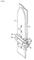
- FIG. 1 is a side view of a timepiece and a timepiece band according to a first embodiment of the invention.
- FIG. 2 is an oblique view showing the clasp of the timepiece band according to the first embodiment of the invention.
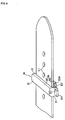
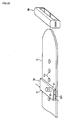
- FIG. 3 shows the first member and the second member of the clasp according to the first embodiment of the invention when separated.
- FIG. 4 is an oblique view of the first attachment member of the first member.
- FIG. 5 is an oblique view of the button unit of the first member.
- FIG. 6 shows the internal arrangement of the button unit.
- FIG. 7 is a partial side section view of the button unit.
- FIG. 8 shows attaching the first attachment member and the button unit to the 6:00 o'clock side band.
- FIG. 9 shows the first attachment member and the button unit when attached to the 6:00 o'clock side band.
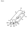
- FIG. 10 is an oblique view of the second member.
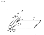
- FIG. 11 shows the second member attached to the 12: 00 o'clock side band.
- FIG. 12 shows buckling the bands with the clasp according to this embodiment of the invention.
- FIG. 13 shows buckling the bands with the clasp according to this embodiment of the invention.
- FIG. 14 shows the bands when buckled together by the clasp according to this embodiment of the invention.
- FIG. 15 shows the first member according to a variation of the first embodiment.
- FIG. 16 shows the first attachment member of the first member in this first variation.
- FIG. 17 shows the button unit of the first member in the first variation.
- FIG. 18 is an oblique view showing the clasp of the timepiece band according to a second embodiment of the invention.
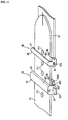
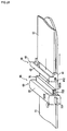
- FIG. 19 shows the first member and the second member of the clasp according to the second embodiment of the invention when separated.
- FIG. 20 is an oblique view of the first member.
- FIG. 21 is an oblique view of the first attachment member of the first member.
- FIG. 22 is an oblique view of the button unit of the first member.
- FIG. 23 shows attaching the first attachment member and the button unit to the 6:00 o'clock side band.
- FIG. 24 shows the first attachment member and the button unit when attached to the 6:00 o'clock side band.
- FIG. 25 shows buckling the bands with the clasp according to this embodiment of the invention.
- FIG. 26 is an oblique view showing the clasp of the timepiece band according to a third embodiment of the invention.
- FIG. 27 shows the first member and the second member of the clasp according to the third embodiment of the invention when separated.
- FIG. 28 is a side view of the first member and the second member.
- FIG. 29 is a horizontal plan view of the first member and the second member.
- FIG. 30 is a section view through A-A in FIG. 29 .
- FIG. 31 is a side view of the first member.
- FIG. 32 shows buckling the bands with the clasp according to this embodiment of the invention.
- FIG. 33 shows the first member in a variation of the third embodiment of the invention.
- FIG. 34 shows another variation of the invention.
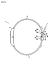
- FIG. 1 is a side view of a wristwatch 1 according to a first embodiment of the invention.
- the wristwatch 1 has a timekeeping unit not shown, a case 2 that houses the timekeeping unit, and leather wrist bands 11 and 12 that are respectively attached to the case 2 at the 6:00 o'clock and 12:00 o'clock positions.
- the free ends of the bands 11 and 12 are joined by a clasp 3.
- FIG. 2 is an oblique view of the clasp 3.
- the clasp 3 has a first member 3A and a second member 3B, and the bands 11 and 12 are held together by engaging the first member 3A and second member 3B with each other.
- the first member 3A is attached at the 6:00 o'clock position of the case 2 and has a plurality of adjustment holes 111 for adjusting the length of the band when the clasp 3 is closed.
- the band 12 is attached at the 12: 00 o'clock position of the case 2.
- FIG. 2 shows the first member 3A and the second member 3B engaged so that the bands 11 and 12 are buckled together
- FIG. 3 shows the first member 3A and the second member 3B when disengaged.
- the 6:00 o'clock band 11 and the 12:00 o'clock band 12 are both belt-like bands in this embodiment of the invention, but the timepiece bands that can be secured by the clasp 3 according to this embodiment of the invention are not limited to such belt-like bands and can be any appropriately configured strap.
- a belt, strap, or bracelet as used herein refers to a member that has a long axis and is longer than it is wide, and includes various belt, strap, band, and other long flat configurations.
- the timepiece band that can be fastened by the clasp 3 of the invention is not limited to such a belt or strap, and could have a block-shaped connector part that is linked to the timepiece case, and an extension part that goes from the connector part to the other side of the timepiece case, and the clasp member could be disposed to the extension part.
- the 6:00 o'clock side band and the 12:00 o'clock side band also do not need to be identically shaped.
- one band could be a belt or strap such as described above, and the other could be any desired shape other than a belt or strap.
- the first member 3A has a first attachment member 20 that is disposed across the width of the 6:00 o'clock side band 11, and a button unit 30.
- the 6:00 o'clock band 11 is disposed between the first attachment member 20 and the button unit 30, and the button unit 30 has a push button 321.
- FIG. 4 shows the first attachment member 20.
- the first attachment member 20 is basically U-shaped with a spine 22 (connecting member) and two side walls 21 that extend through the thickness of the band 11 from the ends of the spine 22 on the opposite sides of the width of the band 11 ( FIG. 3 ) .
- a substantially rectangular opening 211 is formed passing through each of the side walls 21.
- FIG. 5 shows the button unit 30.
- FIG. 6 shows the inside of the button unit 30, and
- FIG. 7 is a partial side section view of the button unit 30.
- FIG. 6 shows the button unit 30 with part of the button unit frame 31 removed.
- the button unit 30 has a button unit frame 31 that is disposed between the side walls 21 of the first attachment member 20 shown in FIG. 4 , button members 32 protruding from openings at the opposite ends of the button unit frame 31, and a stud 33 that is fixed to the bottom of the button unit frame 31 and protrudes from the top of the button unit frame 31.
- the button unit frame 31 is formed with a substantially rectangular section as shown in FIG. 5 by bending and shaping a thin metal sheet, and a hole 311 through which the stud 33 passes is formed where the edges of the thin sheets join.
- a stopper 312 for stopping each of the button members 32 is formed by raising a tab for each from the bottom of the button unit frame 31 as shown in FIG. 6 and FIG. 7 .
- each button member 32 is a flat member having a push button 321 and a protruding catch 322 formed in unison with a notch 323 therebetween.
- the button members 32 are urged to the outside from the inside of the opposite end openings in the button unit frame 31 by corresponding coil springs 324.
- the button members 32 are engaged with the button unit frame 31 by inserting the corresponding stopper 312 into a through-hole 325 formed in each of the button members 32.
- Notches 326 are formed in the button members 32 along both sides of button unit frame 31, and the coil springs 324 are disposed in these notches 326 between the button members 32.
- the push button 321 is flat and rectangularly shaped, and protrudes to the outside from the inside of an opening 211 formed in the side wall 21 of the first attachment member 20 ( FIG. 4 ) .
- the thickness of the push button 321 is slightly less than the height of the opening 211, and the width is slightly less than the width of the opening 211.
- the through-holes 325 in which the stoppers 312 are inserted are sized so that when both push buttons 321 are squeezed together and pushed to the inside across the width of the band 11 ( FIG. 3 ), the distance between the distal ends of the push buttons 321 is less than the distance between the inside faces of the side walls 21, and the push buttons 321 separate from the openings 211 when the push buttons 321 are pushed in to the maximum inside position.
- the spring force of the coil springs 324 preferably causes the stopper 312 to contact the inside end wall of the through-hole 325. This eliminates any play in the push button 321.
- the catches 322 protrude in the direction of the urging force of the coil springs 324 at positions not overlapping the side walls 21 of the first attachment member 20 ( FIG. 4 ).
- the part of the catch 322 on the button unit frame 31 side is a curved incline 322A formed at an angle to both the length and the width of the band 11 ( FIG. 3 ).
- the rise 322B of the catch 322 on the notch 323 side is substantially perpendicular to the length of the band 11.
- the stud 33 is a round column substantially equal in diameter to the diameter of the adjustment holes 111 in the band 11 ( FIG. 3 ), and is crimped to the bottom of the button unit frame 31. Attaching the stud 33 is not limited to crimping, however, and the stud 33 could be fixed to the bottom of the button unit frame 31 by laser welding, for example.
- the stud 33 protrudes from the top of the button unit frame 31 and is inserted to one of the adjustment holes 111 in the band 11, but the height of the stud 33 does not need to equal the thickness of the band 11.
- FIG. 8 and FIG. 9 illustrate attaching the first attachment member 20 and the button unit 30 to the 6:00 o'clock side band 11.
- the first attachment member 20 is positioned to the top side of the band 11, the button unit 30 is positioned on the back side of the band 11 in contact with the wrist, and the band 11 is disposed between the first attachment member 20 and the button unit 30.
- the first attachment member 20 and the button unit 30 are attached to the band 11 at a specific adjustment hole 111 selected according to the desired length of the band when the clasp is closed.
- both push buttons 321 are squeezed together to the inside widthwise to the band 11 as the button unit 30 is inserted between the side walls 21 so that the push buttons 321 then protrude to the outside from the openings 211 in the side walls 21 as shown in FIG. 9 .
- the stud 33 does not escape from the adjustment hole 111 and the planar position of the band 11 to the first attachment member 20 and the button unit 30 is fixed. More specifically, the first attachment member 20 and the button unit 30 are fixed at a specific position to the band 11.
- the push buttons 321 are squeezed together to the inside of the side walls 21 to disengage the openings 211.
- the stud 33 is then repositioned in a different adjustment hole 111 in the band 11, and the push buttons 321 are again squeezed together to reinsert the button unit 30 so that the push buttons 321 again protrude from the openings 211.
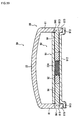
- FIG. 10 is an oblique view of the second member 3B.
- the second member 3B has a second attachment member 40 and a spring pin 50.
- the second attachment member 40 is basically U-shaped in section and is attached to the 12:00 o'clock side band 12.
- the spring pin 50 has a cylinder 51 and catch pins 52.
- the cylinder 51 is passed through a hole 121 formed by wrapping the leather at the end of the band 12 back on itself.
- the catch pins 52 are inserted to the opposite ends of the cylinder 51 and are pushed to the outside from the ends of the cylinder 51 by a spring disposed inside the cylinder 51.
- the second attachment member 40 is substantially U-shaped in section and has a spine 42 connecting two side walls 41.
- the side walls 41 extend from the ends of the spine 42 through the thickness of the band 12 on opposite sides of the width of the band 12.
- the spine 42 spans the width of the band 12 on the front between the side walls 41. Note that the middle part of the spine 42 is a curved convex surface protruding to the outside similarly to the spine 22 of the first attachment member 20.
- a hole 411 that engages a catch pin 52 of the spring pin 50, and a strike recess 412 that captures the catch 322 of the button unit 30 ( FIG. 9 ) inserted thereto, are formed in each of the side walls 41.
- FIG. 11 shows the second attachment member 40 attached to the band 12 by means of the spring pin 50.
- the spring pin 50 is passed through the hole 121 in the band 12
- the catch pins 52 are pushed inside the cylinder 51 as the spring pin 50 is positioned between the opposing side walls 41 of the second attachment member 40, and the catch pins 52 are then caused to engage the holes 411 in the side walls 41.
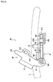
- FIG. 12 is a side view of the wristwatch 1 according to this embodiment of the invention
- FIG. 13 shows sliding the 6 : 00 o'clock side band 11 lengthwise (in the direction of the arrow) .
- the 6:00 o'clock side band 11 and the 12 : 00 o'clock side band 12 slide relative to each other in opposite lengthwise directions so that the ends come together.
- the spine 42 of the second attachment member 40 functions as a guide, and the 6:00 o'clock side band 11 is guided along the length of the band 11 between the side walls 41 of the second attachment member 40.
- each catch 322 contacts the side wall 41, the component force of the force acting longitudinally to the band 11 pushes the catch 322 to the inside widthwise to the band 11, and the catch 322 is guided smoothly into the strike recess 412 in the side walls 41.
- the bands 11 and 12 are thus coupled together as a result of the catches 322 being inserted to the strike recesses 412 from the inside side of the side walls 41.
- the width of the notch 323 is slightly greater than the distance from the edge of the opening 211 to the edge of the side wall 21 along the length of the bands 11 and 12, plus the distance from the edge of the strike recess 412 to the edge of the side wall 21 along the length of the bands 11 and 12.
- the catch 322 does not easily accidentally disengage the strike recess 412 even when a pulling force is applied lengthwise to the bands 11 and 12.
- the push buttons 321 are squeezed together to the inside across the width of the band 11, and the bands 11 and 12 are slid apart. Because squeezing the push buttons 321 together causes the catches 322 to move to the inside widthwise to the band 11 and disengage the strike recesses 412, the bands 11 and 12 can be slid in the directions causing the first member 3A and second member 3B to separate. Note that tensile force produced by the rigidity of the bands 11 and 12 enables the bands 11 and 12 to separate by simply depressing the push buttons 321, and there is no need to intentionally slide the bands 11 and 12 apart.
- This embodiment of the invention has the effects described below.
- the clasp 3 of the wristwatch bands 11 and 12 has a first member 3A and a second member 3B attached to specific positions on the bands 11 and 12, and simply sliding the bands 11 and 12 together in the closing direction causes the catches 322 to engage the strike recesses 412 so that the bands 11 and 12 are fastened together.
- the bands 11 and 12 can therefore be easily buckled together at the desired band length whenever the band is put on.
- the bands 11 and 12 can also be easily unbuckled and separated by simply depressing the push buttons 321 and sliding the bands 11 and 12 apart.
- the bands 11 and 12 can thus be easily coupled and uncoupled by simply sliding the bands 11 and 12 in the appropriate directions, a load is not locally applied to a part of the bands 11 and 12, and the durability of the bands 11 and 12 is thus improved.
- the second attachment member 40 has a spine 42 underneath which the band 11 is passed so that pulling on the band 11 causes the bands 11 and 12 to slide together in opposite directions, the bands 11 and 12 can be easily buckled together using a single hand.
- FIG. 15 shows the first member according to this variation that is attached to the 6:00 o'clock side band 11 ( FIG. 9 ).
- the first member 3A shown in FIG. 9 can be replaced with the first member shown in FIG. 15 .
- this variation of the invention has a second opening 212 formed contiguously to the first opening 211 in each of the side walls 21 of the first attachment member 20.
- the second opening 212 is formed by notching the side wall 21 at the opposite side as the spine 22, and the width of the second opening 212 along the length of the band 11 is less than the width of the first opening 211 along the length of the band 11.
- a neck 351B is formed in the part of the push button 351 that protrudes from the first opening 211 ( FIG. 16 ) by forming a pair of notches 351A in both sides in line with the length of the band 11.
- the width of the notches 351A (the dimension in line with the width of the band 11) is slightly greater than the thickness of the side walls 21 of the first attachment member 20, and the depth of the notches 351A (the dimension in line with the length of the band 11) is slightly greater than 1/2 the difference of the size of the first opening 211 and the size of the second opening 212 in line with the length of the band 11.
- the push buttons 351 are depressed until the notches 351A align with the second openings 212 to insert the necks 351B to the second openings 212, and the push buttons 351 are then pushed into the first openings 211. When the push buttons 351 are then released, the push buttons 351 protrude from the first openings 211.
- the push buttons 351 are depressed to align the notches 351A with the second openings 212, and the push buttons 351 are then removed from the first openings 211 through the second openings 212.
- the first attachment member 20 and the button unit 30 can be easily engaged and disengaged without pushing the push buttons 351 all the way in so that the push buttons 351 are pushed all the way to the inside of the side walls 21. This makes it easier to adjust the size of the band to the user both at the time of purchase in the store and later by the user.
- FIG. 18 to FIG. 25 A second embodiment of the invention is described next with reference to FIG. 18 to FIG. 25 .
- bands 11 and 12 are buckled together with the 12:00 o'clock side band 12 on the bottom (touching the wrist) and the 6:00 o'clock side band 11 on top of the 12:00 o'clock side band 12.
- This arrangement is reversed in this second embodiment of the invention and the bands 11 and 12 are buckled together with the 6:00 o'clock side band 11 on the bottom (touching the wrist) and the 12:00 o'clock side band 12 on top.
- FIG. 18 shows the clasp 6 according to this embodiment of the invention.
- the clasp 6 has a first member 6A and the second member 3B described in the first embodiment.
- FIG. 19 shows the first member 6A and second member 3B when unbuckled
- FIG. 20 shows the first member 6A.
- the first member 6A includes a first attachment member 60 and a button unit 70.
- the first attachment member 60 is disposed across the width of the 6:00 o'clock side band 11, and the button unit 70 is disposed so that the 6:00 o'clock side band 11 is between the button unit 70 and the first attachment member 60.
- FIG. 21 shows the first attachment member 60.
- the first attachment member 60 is substantially rectangular in section, and has a pair of side walls 21 disposed on the opposite sides of the width of the band 11, a spine 22 that connects the side walls 21 on the front side of the band 11, and extensions 23 that continue on the back side of the band 11 from the ends of the side walls 21 to the inside of the width of the band 11.
- FIG. 22 shows the button unit 70.
- the button unit 70 has the same button unit frame 31, button members 32, and stud 33 as the button unit 30 described in the first embodiment (see FIG. 5 ).
- This button unit 70 differs, however, in that the top and bottom orientation of the button unit frame 31 is reversed from the button unit 30 in the first embodiment so that the bottom on which the stud 33 is disposed in the first embodiment is the top, and the stud 33 disposed to the button unit frame 31 protrudes downward (toward the wrist).
- FIG. 23 and FIG. 24 show attaching the first attachment member 60 and the button unit 70 to the band 11.
- the stud 33 of the button unit 70 is inserted to one of the adjustment hole 111 of the band 11, the push buttons 321 are squeezed together to the inside widthwise to the band 11, and the button unit 70 and the band 11 are together inserted to the first attachment member 60.
- the push buttons 321 protrude through the openings 211 in the first attachment member 60, and the band 11 is held between the extensions 23 of the first attachment member 60 ( FIG. 21 ) and the button unit frame 31.
- Buckling the bands 11 and 12 together is described next with reference to FIG. 25 .
- the second attachment member 40 is placed over the top of the 6: 00 o'clock side band 11, the spine 22 of the first attachment member 60 and the spine 42 of the second attachment member 40 are then held respectively with the thumb and index finger, for example, and the first attachment member 60 and the second attachment member 40 are squeezed together.
- This causes the bands 11 and 12 to slide in opposite directions together, and causes the catches 322 of the button unit 70 to enter the strike recesses 412 of the second attachment member 40 and thus hold the bands 11 and 12 together as shown in FIG. 18 .
- the inclines 322A formed on the catches 322 enable the catches 322 to be inserted smoothly to the strike recesses 412 without interference from the side walls 41.
- the push buttons 321 are simply pushed to the inside of the width of the band 11 as described in the first embodiment so that the catches 322 disengage the strike recesses 412, allowing the bands 11 and 12 to separate of their own weight without the user needing to slide them apart.
- this embodiment of the invention also has the following effect.
- the first attachment member 60 and the second attachment member 40 each have a spine 22, 42 spanning the width of the bands 11 and 12, and the bands 11 and 12 are slid together and apart with the second attachment member 40 on top of the band 11, thereby enabling pulling the spines 22 and 42 together.
- the bands 11 and 12 can be easily fastened together using one hand.
- a third embodiment of the invention is described next with reference to FIG. 26 to FIG. 32 .
- This embodiment makes adjusting the length of the band easier, and is characterized by the arrangement of the first member pivotably joining the first attachment member and the button unit.
- FIG. 26 is an oblique view of the clasp 8 in this embodiment of the invention.
- This clasp 8 has a first member 8A and a second member 8B.
- FIG. 27 shows the first member 8A and the second member 8B when unbuckled, and
- FIG. 28 is a side view of the first member 8A and the second member 8B.
- the first member 8A has a first attachment member 80, a button unit 90, a spring pin 901, and a clamping member 902.
- the button unit 90 pivotably connects the first attachment member 80 and the button unit 90.
- the clamping member 902 clamps the band 11 located between the first attachment member 80 and the button unit 90.
- FIG. 28 shows the first attachment member 80 and the button unit 90 pivoted on the spring pin 901 to the open position.
- the first attachment member 80 is substantially U-shaped in section, and has a pair of side walls 81 disposed on the opposite sides of the width of the band 11, and a spine 22 that connects the side walls 81 on the front side of the band 11.
- the spine 22 has a convex curved shape that bulges to the outside in the middle to conform to the section shape of a band that is stitched along the lengthwise edges of the band, that is, on both sides of the width of the band.
- the curved shape of the spine 22 gives the first attachment member 80 a thin appearance.
- pin holes 811 in which the spring pin 901 is inserted, notches 812 in which the push buttons 321 are inserted, recessed pivot locking strikes 813, and lances 814 projecting lengthwise to the band 11 towards the second member 8B are formed in the side walls 81.
- An incline 814A that is inclined both to the length of the band and the height of the side walls 81 is formed on the bottom of each of the lances 814.
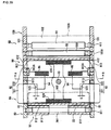
- FIG. 29 is a planar section view of the first member 8A and second member 8B.
- FIG. 30 is a section view through line A-A in FIG. 29.
- FIG. 29 shows the first attachment member 80 and the button unit 90 when closed together as shown in FIG. 27 .
- the button unit 90 has a button unit frame 91 disposed between the side walls 81 of the first attachment member 80, button members 92, pivot locking buttons 94 disposed between the push buttons 321 and the catches 322, and a stud 33 affixed to the bottom of the button unit frame 91 (see FIG. 28 ).
- the button unit frame 91 has wound parts 911, a button holding unit 912 that is substantially rectangular in section, and guide parts 913 (see FIG. 30 ).
- the wound parts 911 are formed by bending a thin metal sheet to wrap around the spring pin 901.
- the guide parts 913 extend along the length of the band 11 and step down towards the wrist from both edges of the button holding unit 912 along the length of the band.
- the length of the guide parts 913 in this embodiment is substantially equal to the size of the button unit frame 91 along the length of the band.
- Stoppers 912A that are bent towards the bottom as shown in FIG. 28 and FIG. 29 are formed at a part of the top outside edge of the button holding unit 912. These stoppers 912A hold the button members 92 and the pivot locking buttons 94 in the button unit frame 91. Part of the shaped edge of the button members 92 and the pivot locking buttons 94 is hidden behind the stoppers 912A, and the stoppers 912A thus contribute to the appearance of the button unit 90.
- the button members 92 are flat members having a push button 321 and a catch 322 formed in unison on opposite sides of a stepped notch 923.
- the pivot locking buttons 94 are flat members conforming to the shape of the notch 923, and are urged to the outside from the inside of the opening in the button unit frame 91 by compressed coil springs 95.
- the pivot locking buttons 94 are disposed in the notches 923 and thereby secured in the button unit frame 91.
- the exposed distal ends of the pivot locking buttons 94 engage the pivot locking strikes 813 of the first attachment member 80.
- the first attachment member 80 and button unit 90 are thus locked in unison by the pivot locking buttons 94 engaging the pivot locking strikes 813.
- An incline 941 that is sloped relative to the height of the side walls 81 of the first attachment member 80 and the width of the band 11 ( FIG. 27 ) is formed on the distal end of each of the pivot locking buttons 94 as shown in FIG. 30 .
- a gap S of a prescribed size widthwise to the band is formed in the notch 923 between the pivot locking button 94 and the button member 92.
- the gap S is sized so that dimension A is smaller than dimension B where dimension A is the distance the button member 92 travels relative to the button unit frame 91 when the catch 322 engages and releases the strike recess 412 in the second attachment member 100, and dimension B is the distance that the button members 92 move relative to the button unit frame 91 when the pivot locking button 94 engages and releases the pivot locking strike 813 in the first attachment member 80.
- gap S is sized so that the distance of travel is substantially equal to dimension A.
- the spring force of the coil springs 324 preferably pushes the catches 322 against the stoppers 912A.
- the spring force of the coil springs 95 preferably pushes the pivot locking buttons 94 against the stoppers 912A. This eliminates play in the button members 92 and the pivot locking buttons 94.
- FIG. 31 is a side view of the first member 8A from the pivot axis end.
- the clamping member 902 has a main body 902A and a wound part 902B.
- the main body 902A is disposed between the band 11 ( FIG. 27 ) and the button unit 90.
- the wound part 902B is disposed between the wound parts 911 of the button unit frame 91 and is wrapped around the spring pin 901.
- the end parts of the clamping member 902 at the opposite sides of the width of the band curve up, press down on the band 11 at both widthwise sides, and prevent the band 11 from moving both in the thickness and width directions.
- the clamping member 902 can thus prevent any play that occurs when a band that is narrower than the distance between the side walls 81 of the first attachment member 80 is used.
- the push buttons 321 ( FIG. 29 ) are pushed inside the button unit frame 91 to release engagement of the pivot locking buttons 94 and pivot locking strikes 813.
- the button members 92 contact the pivot locking buttons 94 and the pivot locking buttons 94 therefore move in conjunction with the push buttons 321 as the push buttons 321 are pushed further inside.
- the distance that the push buttons 321 are pushed until the pivot locking buttons 94 disengage the pivot locking strikes 813 is less in each of the embodiments than the distance that the push buttons 321 are depressed when the push buttons 321 are pushed completely inside the side walls 21 and disengage the openings 211 (see FIG. 8 ).
- the first attachment member 80 and button unit 90 can be pivoted relative to each other as shown in FIG. 28 to change the adjustment hole 111 to which the stud 33 is inserted in the band 11. Because the first attachment member 80 and button unit 90 are linked by a spring pin 901, the first attachment member 80 and button unit 90 do not separate when removed from the band 11 as in the preceding embodiments.
- the first attachment member 80 and button unit 90 are again closed together. This causes the bottom ends 815 shown in FIG. 30 of the side walls 81 of the first attachment member 80 to contact the incline 941 of the opposing pivot locking buttons 94, and the component force of this contact causes the pivot locking buttons 94 to move to the inside of the button unit frame 91.
- the spring force of the coil springs 95 ( FIG. 29 ) then returns the pivot locking buttons 94 to the original position, and the distal ends of the pivot locking buttons 94 are inserted to the pivot locking strikes 813.
- the click of the pivot locking buttons 94 engaging the pivot locking strikes 813 provides a positive response confirming for the user that the clasp closed.
- the second member 8B of this embodiment of the invention is described next. As shown in FIG. 27 to FIG. 29 , the second member 8B has a second attachment member 100, a spring pin 50, and another spring pin 55.
- the second member 8B in this embodiment differs from the second members in the foregoing embodiments in the position of the spine 102 of the second attachment member 100, and in having another spring pin 55 separate from the spring pin 50 that secures the 12:00 o'clock side band 12 to the second attachment member 100.
- This second member 8B is otherwise identical to the second member 3B in the embodiments described above.
- the second attachment member 100 is substantially U-shaped in section view and has side walls 101 on opposite sides of the width of the band 12, and a spine 102 that connects the side walls 101.
- a hole 411 that engages an end of the spring pin 50, a hole 101A that engages an end of the other spring pin 55, a strike recess 412 in which the catch 322 of the button unit 90 is inserted, and a channel 101B that is recessed in line with the length of the band from the first member 8A side are formed in each of the side walls 101.
- An incline 101C is formed at part of the inside face of the channel 101B in the same direction as the incline 814A of the corresponding lance 814 of the first attachment member 80.
- the spring pin 55 passes through a pipe 550 disposed between the side walls 101 as shown in FIG. 29 , and is disposed parallel to the other spring pin 50 at the edges on the opposite sides of the width of the band 12.
- the second attachment member 100 is held at a desired angle of rotation pivoting on the spring pin 50 as a result of this spring pin 55 pressing the end of the band 12. This simplifies passing the 6:00 o'clock side band 11 through the spine 102 when buckling the band.
- the end edge 102A of the spine 102 of the second attachment member 100 is positioned lengthwise to the band 12 on the opposite side of the spring pin 50 as the first member 8A.
- the end edge 102A in this embodiment of the invention is formed substantially parallel to the width of the band, and the entire end edge 102A is located on the opposite side of the spring pin 50 as the first member 8A, but the invention is not so limited. More particularly, only a part of the end edge 102A, such as the parts at the opposite sides of the width of the band, could be positioned on the opposite side of the spring pin 50 as the first member 8A.
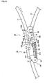
- Buckling the bands 11 and 12 closed by means of the clasp 8 is substantially the same as closing the clasp 3 of the first embodiment.
- FIG. 32 when the 6:00 o'clock side band 11 is passed through the spine 102 and the free end of the band 11 is moved diagonally upwards relative to the 12: 00 o'clock side band 12, the 6: 00 o'clock side band 11 contacts the end edge 102A of the spine 102 at a position on the opposite side of the spring pin 50 as the first member 8A (at position P).
- a component force works at this time in the counterclockwise direction as seen in FIG. 32 (as indicated by the rotating arrow), and simplifies passing the band 11 through the spine 102.
- the second attachment member 100 will pivot in the direction of the rotating arrow and impede sliding the band 11. With the arrangement of this embodiment of the invention, however, the band 11 will not catch on the end edge 102A of the spine 102, and the band 11 will slide smoothly guided by the spine 102.
- the catches 322 move temporarily to the inside of the side walls 81 when the catches 322 engage the strike recesses 412, but the pivot locking buttons 94 do not move because of the gap S ( FIG. 29 ) provided as described above between the button members 92 and pivot locking buttons 94.
- the first attachment member 80 and button unit 90 therefore do not separate from each other.
- the gap S is simply filled and the pivot locking buttons 94 do not move when the push buttons 321 are pushed to unbuckle the bands 11 and 12, the first attachment member 80 and button unit 90 will obviously still not separate.
- the bands 11 and 12 can be prevented from being accidentally unbuckled if a push button 321 is pushed unintentionally.
- this embodiment has the following effects.
- the length of the band 11 can be adjusted without separating the first attachment member 80 and button unit 90 from each other because the first attachment member 80 and button unit 90 are pivotably connected by means of a spring pin 901. This makes adjusting the length of the band even easier.
- Connecting the first attachment member 80 and button unit 90 by means of a spring pin 901 also enables locking the first attachment member 80 and button unit 90 closed by simply rotating them together.
- the pivot locking buttons 94 do not separate from the pivot locking strikes when the catches 322 engage and disengage the strike recesses 412 of the second attachment member 100, and the first attachment member 80 and button unit 90 therefore remain locked closed when the bands are buckled and unbuckled by means of the clasp.
- FIG. 33 shows a first member 8A' according to a variation of the third embodiment.
- This first member 8A' has guide members 103 that are shorter lengthwise to the band than the guide parts 913 in the foregoing third embodiment ( FIG. 28 ).
- These guide members 103 are formed at the part of the button unit frame 91 where the catches 322 are disposed. Because the guide members 103 are not formed below the push buttons 321, the push buttons 321 can be operated more easily in this variation than in the third embodiment described above.
- FIG. 34 shows a variation of the first embodiment.
- the side walls 21' and the spine 22' of the first attachment member 20 extend lengthwise to the band 11 toward the second attachment member 40, and the side walls 41' of the second attachment member 40 extend lengthwise to the band 12 toward the first attachment member 20 in the opposite direction as the direction in which the side walls 21' and spine 22' extend.
- the clasp according to this variation is otherwise substantially identical to the clasp 3 described in the first embodiment ( FIG. 2 ).
- the first attachment member 60 in the second embodiment is substantially rectangular in section, but the first attachment member in this second embodiment could be rendered substantially U-shaped with side walls 41 and a spine connecting the side walls 41 on the wrist side (underside).
- a first attachment member formed with such a U-shaped configuration could be rendered with the arrangement of the variation of the first embodiment shown in FIG. 15 .
- a second opening contiguous to the first opening could be formed as a notch in the side walls of the first attachment member on the opposite end as the spine, and the push buttons could be formed with a necked part that can be inserted through this second opening.
- the stud 33 that is inserted to an adjustment hole 111 in the band 11 in each of the foregoing embodiments is disposed to the button unit, but the invention is not so limited and the stud could be disposed to the spine of the first attachment member.
- the invention also does not necessarily require that a hole is formed in the band or other members fastened by the clasp, and that a stud that is inserted to the hole is disposed to the first attachment member or button unit.
- a hole is formed in the band or other members fastened by the clasp, and that a stud that is inserted to the hole is disposed to the first attachment member or button unit.
- the first attachment member and button unit can be easily and reliably secured to the member that is fastened by the clasp.
- An incline 322A is formed to the catches 322 in the embodiments described above, but this incline could be rendered on an edge part of the side walls of the second attachment member. More specifically, it is sufficient to form an incline with the same slope as the incline 322A on an edge part of the side wall on the side opposing the catch when the bands are slid together. An incline could also be formed on both the catch and the side wall of the second attachment member.
- the button members are held in the button unit frame in the foregoing embodiments by means of the stoppers 312 rising from the bottom of the button unit frame 31 and the stoppers 912A formed by bending an edge part of the button unit frame 91.
- the button members could be held in the button unit frame by means of screws, for example, passing from the button unit frame into holes formed in the button members.
- the arrangement described in the third embodiment whereby the first attachment member 80 and button unit 90 are pivotably connected can also be applied to the arrangement described in the second embodiment whereby the band 11 is held between the button unit 70 and the extensions 23 of the first attachment member 60.
- the pivot axis of the first attachment member 80 and button unit 90 in the third embodiment is disposed to the first member 8A on the opposite end as the second member 8B along the length of the band, but the invention is not so limited and the pivot axis could be located at the second member 8B end of the first member 8A.
- the catches are provided on the second member 8B side of the pivot axis in this case.
- the shaft member pivotably connecting the first attachment member 80 and button unit 90 is also not limited to a spring pin, and any desirably configured member can be used.
- a clasp according to the invention can be used for a variety of applications holding slidable members together.
- the bands 11 and 12 in the embodiments described above are separate members attached to a common case 2, but the invention is not so limited and the bands 11 and 12 could be a single continuous member.
- the embodiments described above describe a clasp that is used to secure a timepiece band, but the clasp of the invention can be used as a clasp for a variety of other accessories.
- Examples of such accessories include belts and bands that wrap around the wrist or waist, chokers that are worn around the next, and clothing clasps.
- the clasp of the invention can also be used other products such as briefcases and handbags, bags and pouches, and footwear.
- the clasp of the invention joins two straps together, but three or more such members can be buckled together by using a plurality of such clasps.
- the clasp of the invention can be used to connect one part with an adjacent part.
Abstract
Description
- The present invention relates to a clasp for securing a coupled member such as a strap or a band. The invention also relates to a band that has this clasp, to a portable device that has the band, to a timepiece, and to an accessory.
- One type of conventional clasp for securing the free ends of a timepiece band has a frame disposed freely pivotably to the band with a protruding stud, and a push button catch that holds the stud with spring force. See, for example, Japanese Unexamined Patent Appl. Pub.
JP-A-H10-28605 - The stud part of this clasp has a small diameter shank that rises from the frame, and a larger diameter head at the distal end of the shank. When the clasp is closed and locked, the stud is inserted through a hole in the band and the large diameter head of the stud protruding from the hole in the band is engaged and held in the hole in the push button catch.
- Some problems with the clasp taught in Japanese Unexamined Patent Appl. Pub.
JP-A-H10-28605 - (1) Every time the band is attached to and removed from the wrist, the stud must pass through a hole in the band. Every time the stud is removed from a hole in the band, the large diameter head of the stud catches the edge of the engaged hole in the band on the back side of the band, and the area around the hole is thus easily damaged. More specifically, when the timepiece is held by the band on the wrist, the rigidity of the band produces tensile force that causes the shank of the stud to be offset from the center of the hole in the band so that the small diameter part of the stud contacts the inside circumference surface of the hole. When the stud is then removed from the hole, the large diameter head catches the edge of the hole in the band, and the area around the hole is thus easily damaged.
- As a result, when the clasp causes the push button catch to engage a stud at a hole in the band, a load acts on only a part of the band when the clasp is opened and closed, and the durability of the band is thus low.
- (2) Aligning the stud with the hole in the band when inserting the stud into the hole can be difficult, and securing the clasp can therefore be difficult. More particularly, the two parts of the band must be correctly positioned together when connecting the two free ends of the band, and the stud attached to the end of the one band must be positioned to the hole in the other band, but the stud is hidden on the back side of the band and is difficult to see.
- Even if the stud is disposed to a position on the opposite side described in Japanese Unexamined Patent Appl. Pub.
JP-A-H10-28605 - Furthermore, if there are multiple holes in the band there is no assurance that the stud will always pass through the desired hole when putting the band on, and the length of the fastened band may therefore differ from the desired length.
- A clasp according to the present invention can be easily opened and closed and affords excellent durability in the band or other secured member.
- Another aspect of the invention is a strap or bracelet having this clasp. A further aspect of the invention is an accessory, a timepiece, or a portable device having this strap or bracelet.
- A clasp according to a first aspect of the invention has a first member and a second member that are respectively disposed to two coupled members, the clasp being closed by the first member and the second member mutually engaging when the coupled members slide in relatively opposite directions. The first member has a first attachment member that has a side wall disposed on both sides of a direction intersecting the direction in which one of the coupledmembers slides, and a spine that connects the side walls, and a button unit that has a push button which is urged to the outside from the inside of the coupled members in the direction intersecting the sliding direction of the coupled members, and which is disposed with the one coupled member held between the first attachment member and the button unit. The second member has a second attachment member that has a side wall attached at a prescribed position to the other coupled member on both sides of a direction intersecting the direction in which the other coupled member slides. The first attachment member and the button unit are attached at a prescribed position to the one coupled member. The button unit has a protruding catch that moves in conjunction with the push button and engages the side walls of the second attachment member when the coupled members are slid together. The side walls of the second attachment member have a recessed strike to which the protruding catch is inserted from the inside of the side walls.
- For convenience and simplicity, the coupled members are referred to herein as "bands, " but the coupled members of the invention are not limited to bands. More particularly, the clasp of the invention is characterized by a first member and a second member that lock together when the coupled members are slid together, and the coupled members can have any shape that enables sliding them together and apart.
- Also for convenience, the direction in which the coupled members slide is below referred to as the length of the bands, and the direction intersecting the sliding direction of the coupledmembers is the width of the bands.
- It will also be noted that the coupled members can be parts of other members.
- The first member having the first attachment member and button unit is attached by a suitable means to a specific position on one of the bands (coupled members). Such a suitable means includes, for example, a stud or wedge that is disposed to either the first attachment member or the button unit and presses and holds the band against the other of the first attachment member and button unit.
- The second member having the second attachment member is attached by a suitable means to the other band (coupled member) at a specific position. For example, the ends of a rod-shaped member disposed across the width of the other band (in the direction intersecting the sliding direction of the bands) could be engaged with the side walls of the second attachment member to attach the second attachment member to a specific position on the other band.
- The first member and the second member are each attached to a specific position on one of the bands, and the band to which the first member is attached and the band to which the second member is attached are slid in mutually opposite directions so that the first member and the second member come together, causing the protruding catch and the recessed strike to engage and thereby lock the first member and second member together.
- The first member and second member thus determine the position where the bands are buckled together, eliminating the need to position the bands to each other when buckling the bands. Furthermore, because the first member and the second member slide together and couple as a result of simply sliding the bands, the bands can be fastened at the desired band length every time the bands are buckled together by means of a simple operation.
- Furthermore, because pressing the push button causes the protruding catch to recede to the inside widthwise to the bands and disengage the recessed strike, the bands can slide apart and the bands can be easily unbuckled.
- The invention also improves the durability of the bands because the bands can be buckled and unbuckled by a simple sliding action, and a wearing load is not locally applied to the bands as a result of passing a stud through hole in the band each time the bands are buckled and unbuckled.
- In the clasp according to another aspect of the invention the second attachment member has a spine connected between the side walls of the second attachment member; and the one coupled member is inserted between the spine of the second attachment member and the other coupled member when the coupled members are slid together.
- This aspect of the invention enables sliding the end of the one band that is disposed between the first attachment member and the button unit between the spine of the second attachment member and the other band to engage the protruding catch and recessed strike. The spine of the second attachment member acts as a guide member in this arrangement so that the one band passed between the spine and the other band can be pulled to engage the protruding catch and recessed strike, and the bands can be easily buckled together with one hand.
- In another aspect of the invention, when the one coupled member is attached to the attached object to which the coupled members are attached, the one coupled member is located on the attached object side of the button unit, and the coupled members are slid with the second attachment member placed on the button unit side of the one coupled member.
- With this aspect of the invention the second attachment member is placed on one band, and the first attachment member and the second attachment member are squeezed together using the thumb and index finger, for example, thus causing the bands to slide in opposite directions together and the protruding catch and recessed strike to engage. The bands can thus be easily buckled together with one hand.
- The attached object to which the bands are attached is, for example, the wrist, and the first attachment member, the one band, and the button unit are arranged in order from the attached object (wrist) side through the thickness of the bands.
- In another aspect of the invention, the spine of the first member or the button unit has a stud that protrudes toward the other of the spine and the button unit, and the stud is inserted to a hole formed in the one coupled member.
- Because the planar position of the first attachment member and button unit to the band is determined by inserting the stud to a hole in the band, the first attachment member and button unit can be reliably fixed to a specific position on the band.
- The diameter of the stud can be the same along the entire length of the stud.
- Further preferably, an opening is formed in the side walls of the first attachment member, and the first attachment member and the button unit are assembled in unison by means of the push button passing through the opening.
- When the first member is attached to one band, the band is disposed between the first attachment member and the button unit, the push buttons are pressed inside the side walls of the first attachment member (to the inside widthwise to the bands) and the button unit is placed between the side walls of the first attachment member so that the push buttons pass through the openings in the side walls and protrude to the outside of the side walls of the first attachment member (to the outside widthwise to the bands).
- By forming openings in the side walls of the first attachment member, this aspect of the invention enables assembling the first attachment member and button unit in unison by means of a simple construction.
- In the clasp according to another aspect of the invention, the first attachment member is substantially U-shaped with the side walls rising from the opposite ends of the spine; a second opening is notched into the side walls of the first attachment member from the opposite end as the spine so that the second opening is continuous to a first opening, which is an opening through which the push button passes; the size of the second opening is smaller than the size of the first opening in the sliding direction of the coupled members; and a necked part that can be inserted to the second opening is formed in the part of the push button that protrudes from the first opening when the push button is not depressed.
- To attach the first attachment member and button unit to one of the bands with this aspect of the invention, the push button is depressed, the necked part is inserted to the second opening and the push button is then pushed into the first opening so that the push button protrudes from the first opening.
- To remove the first attachment member and button unit from the band, the push button is pressed to align the necked part with the second opening so that the push button can be removed from the first attachment member through the second opening.
- This arrangement enables easily connecting and disconnecting the first attachment member and button unit without pushing the push button all the way inside the side walls, and thus makes attaching the first attachment member and button unit to the band easier.
- In a clasp according to another aspect of the invention, the first attachment member and the button unit are connected to pivot relative to the other on a shaft unit disposed in the direction intersecting the sliding direction of the coupled members; the button unit has a pivot locking button that is urged to the outside from the inside of the coupled members in the direction intersecting the sliding direction of the coupled members and engages the side walls of the first attachment member, and a button unit frame that holds the push button, the protruding catch, and the pivot locking button; the side walls of the second attachment member have a recessed pivot locking recess in which the pivot locking button is inserted from the inside of the side walls; the pivot locking button opposes the push button or protruding catch with a gap therebetween in the direction the push button is depressed; and the gap is sized so that A is less than B where A is the distance the push button moves relative to the button unit frame when the protruding catch engages and releases the recessed strike, and B is the distance that the push button moves relative to the button unit frame when the pivot locking button engages and releases the pivot locking recess.
- This aspect of the invention enables securing the first attachment member and button unit in unison by simply pivoting the first attachment member and button unit together so that the pivot locking button and pivot locking recess engage. In addition, the band can be moved lengthwise between the first attachment member and the button unit by pushing the push button in further than needed to disengage the protruding catch from the recessed strike so that the pivot locking button disengages the pivot locking recess and the first attachment member and button unit can pivot open.
- By pivotably connecting the first attachment member and the button unit, this aspect of the invention enables adjusting the length of the band without disassembling the first attachment member and button unit. More particularly, usability is improved because the first attachment member and button unit are not completely disconnected from each other in order to adjust the length of the band.
- Furthermore, by connecting the first attachment member and the button unit with a pivot pin, the first attachment member and button unit can be closed by a pivot action. This arrangement makes adjusting the length of the band simple.
- The pivot locking button is assembled to the push button or protruding catch so that the gap therebetween satisfies the relationship between distance A and distance B described above. This prevents the pivot locking button from disengaging the pivot locking recess when the protruding catch moves inside the side wall of the secondmember when buckling the bands together. The pivot locking button is also prevented from disengaging the pivot locking recess when the push button is pushed in to unbuckle the bands and the protruding catch moves inside the side wall of the second member in conjunction with this movement of the push button. The first attachment member and button unit thus do not separate when the clasp is operated to buckle and unbuckle the bands.
- In a clasp according to another aspect of the invention, an inclined face is formed on at least one of the end part on the first attachment member side of the pivot locking button in the pivoting direction in which the first attachment member and the button unit come together, and the end part on the button unit side of the side wall of the first attachment member in said pivoting direction. This inclined face is sloped in the direction causing a component force to work toward the inside of the side walls of the first attachment member when the first attachment member and the button unit pivot together and the pivot locking button and the side wall of the first attachment member touch.
- This inclined face can be a linear taper with a constant slope, or the inclined face can be a curved surface with a slope that is not constant.
- When the pivot locking button contacts the side wall of the first attachment member when the first attachment member and the button unit pivot closed, a component force of this pivot action is transferred by the incline to the pivot locking button, causing the pivot locking button to move to the inside widthwise to the band and be guided into the pivot locking recess. The first attachment member and button unit can thus be smoothly closed and locked together.
- In a clasp according to another aspect of the invention an inclined face is formed on at least one of the second member side end part of the protruding catch in the sliding direction of the coupled member, and the first member side end part of the second attachment member side walls in the sliding direction of the coupled member. This inclined face is sloped in the direction causing a component force to work toward the inside of the side walls of the first attachment member when the protruding catch and the side walls of the second attachment member touch because the coupled members are slid together.
- This inclined face can be a linear taper with a constant slope, or the inclined face can be a curved surface with a slope that is not constant.
- When the protruding catch contacts the side wall of the second attachment member when the bands are slid together, a component force of this action is transferred by the incline and causes the protruding catch to move to the inside widthwise to the band and be guided into the recessed strike. The bands can thus be smoothly slid together and fastened.
- Yet further preferably, the second member comprises a spring pin having a rod member that is inserted in a cylinder and is pushed freely to the outside by a spring, and the side walls of the second attachment member are attached by the spring pin to the other coupled member.
- This aspect of the invention enables freely connecting and disconnecting the second attachment member to the band by means of the spring pin, and thus makes changing the band easy.
- Yet further preferably, the push button and the protruding catch are formed as parts of a single flat member, and a notch that holds a part of a side wall of the first attachment member and a part of a side wall of the second attachment member is formed between the push button and the protruding catch.
- By forming a cut-out notch in sheet material so that both sides of the notch render the push button and protruding catch, this aspect of the invention enables easily achieving an arrangement whereby the protruding catch and push button move together, and the protruding catch is inserted to the recessed strike of the second attachment member when the push button is inserted to the opening in the first attachment member.
- Another aspect of the invention is a band that has the clasp of the invention described above.
- By using the clasp of the invention, this aspect of the invention achieves the same action and effect described above.
- Another aspect of the invention is a portable device that has the band of the invention described above.
- By using the band having a clasp as described above, this aspect of the invention achieves the same action and effect described above.
- Examples of the portable device include data devices, communication devices, memory cards, cameras, andmeasurementdevices.
- Another aspect of the invention is a timepiece having the band described above with the band connected to the timepiece case.
- By using the band having a clasp as described above, this aspect of the invention achieves the same action and effect described above.
- The band in this case is preferably a timepiece band.
- The timepiece band can be made of any desirable material, including leather, cloth, plastic, and metal.
- Another aspect of the invention is an accessory having the band described above so that the accessory can be worn by means of the band.
- By using the band having a clasp as described above, this aspect of the invention achieves the same action and effect described above.
- The invention enables easily locking and unlocking the clasp with a simple operation, and greatly improves the durability of the secured strap or other member because the clasp does not impose a load on only a part of the strap or secured member.
- Other objects and attainments together with a fuller understanding of the invention will become apparent and appreciated by referring to the following description and claims taken in conjunction with the accompanying drawings.
-
FIG. 1 is a side view of a timepiece and a timepiece band according to a first embodiment of the invention. -
FIG. 2 is an oblique view showing the clasp of the timepiece band according to the first embodiment of the invention. -
FIG. 3 shows the first member and the second member of the clasp according to the first embodiment of the invention when separated. -
FIG. 4 is an oblique view of the first attachment member of the first member. -
FIG. 5 is an oblique view of the button unit of the first member. -
FIG. 6 shows the internal arrangement of the button unit. -
FIG. 7 is a partial side section view of the button unit. -
FIG. 8 shows attaching the first attachment member and the button unit to the 6:00 o'clock side band. -
FIG. 9 shows the first attachment member and the button unit when attached to the 6:00 o'clock side band. -
FIG. 10 is an oblique view of the second member. -
FIG. 11 shows the second member attached to the 12: 00 o'clock side band. -
FIG. 12 shows buckling the bands with the clasp according to this embodiment of the invention. -
FIG. 13 shows buckling the bands with the clasp according to this embodiment of the invention. -
FIG. 14 shows the bands when buckled together by the clasp according to this embodiment of the invention. -
FIG. 15 shows the first member according to a variation of the first embodiment. -
FIG. 16 shows the first attachment member of the first member in this first variation. -
FIG. 17 shows the button unit of the first member in the first variation. -
FIG. 18 is an oblique view showing the clasp of the timepiece band according to a second embodiment of the invention. -
FIG. 19 shows the first member and the second member of the clasp according to the second embodiment of the invention when separated. -
FIG. 20 is an oblique view of the first member. -
FIG. 21 is an oblique view of the first attachment member of the first member. -
FIG. 22 is an oblique view of the button unit of the first member. -
FIG. 23 shows attaching the first attachment member and the button unit to the 6:00 o'clock side band. -
FIG. 24 shows the first attachment member and the button unit when attached to the 6:00 o'clock side band. -
FIG. 25 shows buckling the bands with the clasp according to this embodiment of the invention. -
FIG. 26 is an oblique view showing the clasp of the timepiece band according to a third embodiment of the invention. -
FIG. 27 shows the first member and the second member of the clasp according to the third embodiment of the invention when separated. -
FIG. 28 is a side view of the first member and the second member. -
FIG. 29 is a horizontal plan view of the first member and the second member. -
FIG. 30 is a section view through A-A inFIG. 29 . -
FIG. 31 is a side view of the first member. -
FIG. 32 shows buckling the bands with the clasp according to this embodiment of the invention. -
FIG. 33 shows the first member in a variation of the third embodiment of the invention. -
FIG. 34 shows another variation of the invention. - Preferred embodiments of the present invention are described below with reference to the accompanying figures. Note that in the second and subsequent embodiments parts that are functionally the same as parts that have already been described in the first embodiment are identified by the same reference numerals, and further description thereof is omitted.
- * Embodiment 1
- A first embodiment of the invention is described next.
- 1. General arrangement
-
FIG. 1 is a side view of a wristwatch 1 according to a first embodiment of the invention. The wristwatch 1 has a timekeeping unit not shown, acase 2 that houses the timekeeping unit, andleather wrist bands case 2 at the 6:00 o'clock and 12:00 o'clock positions. The free ends of thebands clasp 3. - 2. Clasp
-
FIG. 2 is an oblique view of theclasp 3. Theclasp 3 has afirst member 3A and asecond member 3B, and thebands first member 3A andsecond member 3B with each other. Thefirst member 3A is attached at the 6:00 o'clock position of thecase 2 and has a plurality of adjustment holes 111 for adjusting the length of the band when theclasp 3 is closed. Theband 12 is attached at the 12: 00 o'clock position of thecase 2.FIG. 2 shows thefirst member 3A and thesecond member 3B engaged so that thebands FIG. 3 shows thefirst member 3A and thesecond member 3B when disengaged. - The 6:00
o'clock band 11 and the 12:00o'clock band 12 are both belt-like bands in this embodiment of the invention, but the timepiece bands that can be secured by theclasp 3 according to this embodiment of the invention are not limited to such belt-like bands and can be any appropriately configured strap. - A belt, strap, or bracelet as used herein refers to a member that has a long axis and is longer than it is wide, and includes various belt, strap, band, and other long flat configurations.
- Furthermore, the timepiece band that can be fastened by the
clasp 3 of the invention is not limited to such a belt or strap, and could have a block-shaped connector part that is linked to the timepiece case, and an extension part that goes from the connector part to the other side of the timepiece case, and the clasp member could be disposed to the extension part. - The 6:00 o'clock side band and the 12:00 o'clock side band also do not need to be identically shaped. For example, one band could be a belt or strap such as described above, and the other could be any desired shape other than a belt or strap.
- 3. First member
- As shown in
FIG. 3 , thefirst member 3A has afirst attachment member 20 that is disposed across the width of the 6:00o'clock side band 11, and abutton unit 30. The 6:00o'clock band 11 is disposed between thefirst attachment member 20 and thebutton unit 30, and thebutton unit 30 has apush button 321. - 3-1. First attachment member
-
FIG. 4 shows thefirst attachment member 20. Thefirst attachment member 20 is basically U-shaped with a spine 22 (connecting member) and twoside walls 21 that extend through the thickness of theband 11 from the ends of thespine 22 on the opposite sides of the width of the band 11 (FIG. 3 ) . A substantiallyrectangular opening 211 is formed passing through each of theside walls 21. - 3-2. Button unit
-
FIG. 5 shows thebutton unit 30.FIG. 6 shows the inside of thebutton unit 30, andFIG. 7 is a partial side section view of thebutton unit 30.FIG. 6 shows thebutton unit 30 with part of thebutton unit frame 31 removed. - As shown in
FIG. 5 andFIG. 6 , thebutton unit 30 has abutton unit frame 31 that is disposed between theside walls 21 of thefirst attachment member 20 shown inFIG. 4 ,button members 32 protruding from openings at the opposite ends of thebutton unit frame 31, and astud 33 that is fixed to the bottom of thebutton unit frame 31 and protrudes from the top of thebutton unit frame 31. - The
button unit frame 31 is formed with a substantially rectangular section as shown inFIG. 5 by bending and shaping a thin metal sheet, and ahole 311 through which thestud 33 passes is formed where the edges of the thin sheets join. - A
stopper 312 for stopping each of thebutton members 32 is formed by raising a tab for each from the bottom of thebutton unit frame 31 as shown inFIG. 6 and FIG. 7 . - As shown in
FIG. 6 , eachbutton member 32 is a flat member having apush button 321 and aprotruding catch 322 formed in unison with anotch 323 therebetween. Thebutton members 32 are urged to the outside from the inside of the opposite end openings in thebutton unit frame 31 by corresponding coil springs 324. Thebutton members 32 are engaged with thebutton unit frame 31 by inserting thecorresponding stopper 312 into a through-hole 325 formed in each of thebutton members 32. -
Notches 326 are formed in thebutton members 32 along both sides ofbutton unit frame 31, and the coil springs 324 are disposed in thesenotches 326 between thebutton members 32. - The
push button 321 is flat and rectangularly shaped, and protrudes to the outside from the inside of anopening 211 formed in theside wall 21 of the first attachment member 20 (FIG. 4 ) . The thickness of thepush button 321 is slightly less than the height of theopening 211, and the width is slightly less than the width of theopening 211. - The through-
holes 325 in which thestoppers 312 are inserted are sized so that when both pushbuttons 321 are squeezed together and pushed to the inside across the width of the band 11 (FIG. 3 ), the distance between the distal ends of thepush buttons 321 is less than the distance between the inside faces of theside walls 21, and thepush buttons 321 separate from theopenings 211 when thepush buttons 321 are pushed in to the maximum inside position. - When the
push buttons 321 are not pushed in against the force of thecompressed coil springs 324, the spring force of the coil springs 324 preferably causes thestopper 312 to contact the inside end wall of the through-hole 325. This eliminates any play in thepush button 321. - The
catches 322 protrude in the direction of the urging force of the coil springs 324 at positions not overlapping theside walls 21 of the first attachment member 20 (FIG. 4 ). The part of thecatch 322 on thebutton unit frame 31 side is acurved incline 322A formed at an angle to both the length and the width of the band 11 (FIG. 3 ). Therise 322B of thecatch 322 on thenotch 323 side is substantially perpendicular to the length of theband 11. - The
stud 33 is a round column substantially equal in diameter to the diameter of the adjustment holes 111 in the band 11 (FIG. 3 ), and is crimped to the bottom of thebutton unit frame 31. Attaching thestud 33 is not limited to crimping, however, and thestud 33 could be fixed to the bottom of thebutton unit frame 31 by laser welding, for example. Thestud 33 protrudes from the top of thebutton unit frame 31 and is inserted to one of the adjustment holes 111 in theband 11, but the height of thestud 33 does not need to equal the thickness of theband 11. - 3-3. Attaching the first member to the band
-
FIG. 8 andFIG. 9 illustrate attaching thefirst attachment member 20 and thebutton unit 30 to the 6:00o'clock side band 11. Thefirst attachment member 20 is positioned to the top side of theband 11, thebutton unit 30 is positioned on the back side of theband 11 in contact with the wrist, and theband 11 is disposed between thefirst attachment member 20 and thebutton unit 30. Thefirst attachment member 20 and thebutton unit 30 are attached to theband 11 at aspecific adjustment hole 111 selected according to the desired length of the band when the clasp is closed. - To attach the
first attachment member 20 andbutton unit 30 to theband 11, thestud 33 is inserted to aparticular adjustment hole 111 as shown inFIG. 8 , both pushbuttons 321 are squeezed together to the inside widthwise to theband 11 as thebutton unit 30 is inserted between theside walls 21 so that thepush buttons 321 then protrude to the outside from theopenings 211 in theside walls 21 as shown inFIG. 9 . - Because the
band 11 is between thefirst attachment member 20 and thebutton unit 30, and thestud 33 is inserted to theadjustment hole 111 between thefirst attachment member 20 and thebutton unit 30, thestud 33 does not escape from theadjustment hole 111 and the planar position of theband 11 to thefirst attachment member 20 and thebutton unit 30 is fixed. More specifically, thefirst attachment member 20 and thebutton unit 30 are fixed at a specific position to theband 11. - To adjust the position of the
first attachment member 20 andbutton unit 30 on theband 11, thepush buttons 321 are squeezed together to the inside of theside walls 21 to disengage theopenings 211. Thestud 33 is then repositioned in adifferent adjustment hole 111 in theband 11, and thepush buttons 321 are again squeezed together to reinsert thebutton unit 30 so that thepush buttons 321 again protrude from theopenings 211. - 4. Second member
- The arrangement of the
second member 3B that is attached to the 12:00 o'clock side band 12 (FIG. 3 ) is described next. -
FIG. 10 is an oblique view of thesecond member 3B. Thesecond member 3B has asecond attachment member 40 and aspring pin 50. Thesecond attachment member 40 is basically U-shaped in section and is attached to the 12:00o'clock side band 12. - The
spring pin 50 has acylinder 51 and catch pins 52. Thecylinder 51 is passed through ahole 121 formed by wrapping the leather at the end of theband 12 back on itself. The catch pins 52 are inserted to the opposite ends of thecylinder 51 and are pushed to the outside from the ends of thecylinder 51 by a spring disposed inside thecylinder 51. - The
second attachment member 40 is substantially U-shaped in section and has aspine 42 connecting twoside walls 41. Theside walls 41 extend from the ends of thespine 42 through the thickness of theband 12 on opposite sides of the width of theband 12. Thespine 42 spans the width of theband 12 on the front between theside walls 41. Note that the middle part of thespine 42 is a curved convex surface protruding to the outside similarly to thespine 22 of thefirst attachment member 20. - A
hole 411 that engages acatch pin 52 of thespring pin 50, and astrike recess 412 that captures thecatch 322 of the button unit 30 (FIG. 9 ) inserted thereto, are formed in each of theside walls 41. -
FIG. 11 shows thesecond attachment member 40 attached to theband 12 by means of thespring pin 50. When thesecond attachment member 40 is attached to theband 12, thespring pin 50 is passed through thehole 121 in theband 12, the catch pins 52 are pushed inside thecylinder 51 as thespring pin 50 is positioned between the opposingside walls 41 of thesecond attachment member 40, and the catch pins 52 are then caused to engage theholes 411 in theside walls 41. - 5. Securing the band by means of the clasp
- The operation for fastening the
bands clasp 3 and attaching the wristwatch 1 on the wrist (as an example of where the wristwatch 1 is worn) is described next with reference toFIG. 12 to FIG. 14 . -
FIG. 12 is a side view of the wristwatch 1 according to this embodiment of the invention, andFIG. 13 shows sliding the 6 : 00o'clock side band 11 lengthwise (in the direction of the arrow) . When the end part of the 6:00o'clock side band 11 is inserted between thespine 42 of thesecond attachment member 40 and the 12:00o'clock side band 12, and the end part of the 6:00o'clock side band 11 is then pulled as shown inFIG. 12 andFIG. 13 , the 6:00o'clock side band 11 and the 12 : 00o'clock side band 12 slide relative to each other in opposite lengthwise directions so that the ends come together. Thespine 42 of thesecond attachment member 40 functions as a guide, and the 6:00o'clock side band 11 is guided along the length of theband 11 between theside walls 41 of thesecond attachment member 40. - When the 6:00
o'clock side band 11 is thus slid relative to the 12:00o'clock side band 12, thefirst member 3A and thesecond member 3B come together, thecatches 322 of thebutton unit 30 engage the strike recesses 412 in theside walls 41 of thesecond attachment member 40 from the inside surface of theside walls 41, and thebands Fig. 14 ). - As a result of this sliding action of the 6:00
o'clock side band 11, theincline 322A of eachcatch 322 contacts theside wall 41, the component force of the force acting longitudinally to theband 11 pushes thecatch 322 to the inside widthwise to theband 11, and thecatch 322 is guided smoothly into thestrike recess 412 in theside walls 41. Thebands catches 322 being inserted to the strike recesses 412 from the inside side of theside walls 41. - When the
bands side walls 21 of thefirst attachment member 20 and part of theside walls 41 of thesecond attachment member 40 are held in thenotches 323 between thepush buttons 321 and thecatches 322. More specifically, the width of thenotch 323 is slightly greater than the distance from the edge of theopening 211 to the edge of theside wall 21 along the length of thebands strike recess 412 to the edge of theside wall 21 along the length of thebands - Furthermore, because the
rise 322B of thecatch 322 is substantially perpendicular to the length of theband 11, thecatch 322 does not easily accidentally disengage thestrike recess 412 even when a pulling force is applied lengthwise to thebands - To unbuckle the
bands push buttons 321 are squeezed together to the inside across the width of theband 11, and thebands push buttons 321 together causes thecatches 322 to move to the inside widthwise to theband 11 and disengage the strike recesses 412, thebands first member 3A andsecond member 3B to separate. Note that tensile force produced by the rigidity of thebands bands push buttons 321, and there is no need to intentionally slide thebands - 6. Effect of the invention
- This embodiment of the invention has the effects described below.
- (1) The
clasp 3 of thewristwatch bands first member 3A and asecond member 3B attached to specific positions on thebands bands catches 322 to engage the strike recesses 412 so that thebands bands - The
bands push buttons 321 and sliding thebands - The
bands bands bands bands - (2) By inserting the 6: 00
o'clock side band 11 between thefirst attachment member 20 and thebutton unit 30, and inserting thestud 33 to anadjustment hole 111 in theband 11 between thefirst attachment member 20 and thebutton unit 30, the first attachment member and the button unit can be reliably attached to the band at a specific desired position. - (3) By forming an
incline 322A on thecatch 322 so that a component force acting on theincline 322A causes thecatch 322 to be inserted smoothly to thestrike recess 412, the sliding action of theband 11 is rendered even easier. - (4) Because the
second member 3B can be disassembled into thesecond attachment member 40 and thespring pin 50, theband 12 can be easily replaced. - (5) Because the
second attachment member 40 has aspine 42 underneath which theband 11 is passed so that pulling on theband 11 causes thebands bands - * Variation of embodiment 1
- A variation of the foregoing first embodiment is described next with reference to
FIG. 15 to FIG. 17 . -
FIG. 15 shows the first member according to this variation that is attached to the 6:00 o'clock side band 11 (FIG. 9 ). Thefirst member 3A shown inFIG. 9 can be replaced with the first member shown inFIG. 15 . - As shown in
FIG. 16 , this variation of the invention has asecond opening 212 formed contiguously to thefirst opening 211 in each of theside walls 21 of thefirst attachment member 20. Thesecond opening 212 is formed by notching theside wall 21 at the opposite side as thespine 22, and the width of thesecond opening 212 along the length of theband 11 is less than the width of thefirst opening 211 along the length of theband 11. - As shown in
FIG. 17 , aneck 351B is formed in the part of thepush button 351 that protrudes from the first opening 211 (FIG. 16 ) by forming a pair ofnotches 351A in both sides in line with the length of theband 11. The width of thenotches 351A (the dimension in line with the width of the band 11) is slightly greater than the thickness of theside walls 21 of thefirst attachment member 20, and the depth of thenotches 351A (the dimension in line with the length of the band 11) is slightly greater than 1/2 the difference of the size of thefirst opening 211 and the size of thesecond opening 212 in line with the length of theband 11. - To attach the
first attachment member 20 and thebutton unit 30 to theband 11 in this variation of the invention, thepush buttons 351 are depressed until thenotches 351A align with thesecond openings 212 to insert thenecks 351B to thesecond openings 212, and thepush buttons 351 are then pushed into thefirst openings 211. When thepush buttons 351 are then released, thepush buttons 351 protrude from thefirst openings 211. - To remove the
first attachment member 20 and thebutton unit 30 from theband 11, thepush buttons 351 are depressed to align thenotches 351A with thesecond openings 212, and thepush buttons 351 are then removed from thefirst openings 211 through thesecond openings 212. - With this variation of the invention the
first attachment member 20 and thebutton unit 30 can be easily engaged and disengaged without pushing thepush buttons 351 all the way in so that thepush buttons 351 are pushed all the way to the inside of theside walls 21. This makes it easier to adjust the size of the band to the user both at the time of purchase in the store and later by the user. - *
Embodiment 2 - A second embodiment of the invention is described next with reference to
FIG. 18 to FIG. 25 . In the first embodiment as shown inFIG. 2 andFIG. 3 bands o'clock side band 12 on the bottom (touching the wrist) and the 6:00o'clock side band 11 on top of the 12:00o'clock side band 12. This arrangement is reversed in this second embodiment of the invention and thebands o'clock side band 11 on the bottom (touching the wrist) and the 12:00o'clock side band 12 on top. -
FIG. 18 shows theclasp 6 according to this embodiment of the invention. Theclasp 6 has afirst member 6A and thesecond member 3B described in the first embodiment. -
FIG. 19 shows thefirst member 6A andsecond member 3B when unbuckled, andFIG. 20 shows thefirst member 6A. - The
first member 6A includes afirst attachment member 60 and abutton unit 70. Thefirst attachment member 60 is disposed across the width of the 6:00o'clock side band 11, and thebutton unit 70 is disposed so that the 6:00o'clock side band 11 is between thebutton unit 70 and thefirst attachment member 60. -
FIG. 21 shows thefirst attachment member 60. Thefirst attachment member 60 is substantially rectangular in section, and has a pair ofside walls 21 disposed on the opposite sides of the width of theband 11, aspine 22 that connects theside walls 21 on the front side of theband 11, andextensions 23 that continue on the back side of theband 11 from the ends of theside walls 21 to the inside of the width of theband 11. -
FIG. 22 shows thebutton unit 70. Thebutton unit 70 has the samebutton unit frame 31,button members 32, andstud 33 as thebutton unit 30 described in the first embodiment (seeFIG. 5 ). Thisbutton unit 70 differs, however, in that the top and bottom orientation of thebutton unit frame 31 is reversed from thebutton unit 30 in the first embodiment so that the bottom on which thestud 33 is disposed in the first embodiment is the top, and thestud 33 disposed to thebutton unit frame 31 protrudes downward (toward the wrist). -
FIG. 23 andFIG. 24 show attaching thefirst attachment member 60 and thebutton unit 70 to theband 11. - As shown in
FIG. 23 thestud 33 of thebutton unit 70 is inserted to one of theadjustment hole 111 of theband 11, thepush buttons 321 are squeezed together to the inside widthwise to theband 11, and thebutton unit 70 and theband 11 are together inserted to thefirst attachment member 60. As a result, thepush buttons 321 protrude through theopenings 211 in thefirst attachment member 60, and theband 11 is held between theextensions 23 of the first attachment member 60 (FIG. 21 ) and thebutton unit frame 31. - Buckling the
bands FIG. 25 . In this embodiment thesecond attachment member 40 is placed over the top of the 6: 00o'clock side band 11, thespine 22 of thefirst attachment member 60 and thespine 42 of thesecond attachment member 40 are then held respectively with the thumb and index finger, for example, and thefirst attachment member 60 and thesecond attachment member 40 are squeezed together. This causes thebands catches 322 of thebutton unit 70 to enter the strike recesses 412 of thesecond attachment member 40 and thus hold thebands FIG. 18 . As described in the first embodiment, the inclines 322A formed on thecatches 322 enable thecatches 322 to be inserted smoothly to the strike recesses 412 without interference from theside walls 41. - To unbuckle the
bands push buttons 321 are simply pushed to the inside of the width of theband 11 as described in the first embodiment so that thecatches 322 disengage the strike recesses 412, allowing thebands - In addition to the effects of the first embodiment described in (1) to (4) above, this embodiment of the invention also has the following effect.
- (6) The
first attachment member 60 and thesecond attachment member 40 each have aspine bands bands second attachment member 40 on top of theband 11, thereby enabling pulling thespines bands - *
Embodiment 3 - A third embodiment of the invention is described next with reference to
FIG. 26 to FIG. 32 . This embodiment makes adjusting the length of the band easier, and is characterized by the arrangement of the first member pivotably joining the first attachment member and the button unit. -
FIG. 26 is an oblique view of the clasp 8 in this embodiment of the invention. This clasp 8 has afirst member 8A and asecond member 8B.FIG. 27 shows thefirst member 8A and thesecond member 8B when unbuckled, andFIG. 28 is a side view of thefirst member 8A and thesecond member 8B. - As shown in
FIG. 28 , the first member 8Ahas afirst attachment member 80, abutton unit 90, aspring pin 901, and a clampingmember 902. Thebutton unit 90 pivotably connects thefirst attachment member 80 and thebutton unit 90. The clampingmember 902 clamps theband 11 located between thefirst attachment member 80 and thebutton unit 90.FIG. 28 shows thefirst attachment member 80 and thebutton unit 90 pivoted on thespring pin 901 to the open position. - As shown in
FIG. 27 , thefirst attachment member 80 is substantially U-shaped in section, and has a pair ofside walls 81 disposed on the opposite sides of the width of theband 11, and aspine 22 that connects theside walls 81 on the front side of theband 11. Thespine 22 has a convex curved shape that bulges to the outside in the middle to conform to the section shape of a band that is stitched along the lengthwise edges of the band, that is, on both sides of the width of the band. The curved shape of thespine 22 gives the first attachment member 80 a thin appearance. - As shown in
FIG. 27 andFIG. 28 , pin holes 811 in which thespring pin 901 is inserted,notches 812 in which thepush buttons 321 are inserted, recessedpivot locking strikes 813, and lances 814 projecting lengthwise to theband 11 towards thesecond member 8B are formed in theside walls 81. Anincline 814A that is inclined both to the length of the band and the height of theside walls 81 is formed on the bottom of each of thelances 814. -
FIG. 29 is a planar section view of thefirst member 8A andsecond member 8B.FIG. 30 is a section view through line A-A inFIG. 29. FIG. 29 shows thefirst attachment member 80 and thebutton unit 90 when closed together as shown inFIG. 27 . - As shown in
FIG. 28 andFIG. 29 , thebutton unit 90 has abutton unit frame 91 disposed between theside walls 81 of thefirst attachment member 80,button members 92,pivot locking buttons 94 disposed between thepush buttons 321 and thecatches 322, and astud 33 affixed to the bottom of the button unit frame 91 (seeFIG. 28 ). - As shown in
FIG. 27 andFIG. 28 , thebutton unit frame 91 has woundparts 911, abutton holding unit 912 that is substantially rectangular in section, and guide parts 913 (seeFIG. 30 ). Thewound parts 911 are formed by bending a thin metal sheet to wrap around thespring pin 901. Theguide parts 913 extend along the length of theband 11 and step down towards the wrist from both edges of thebutton holding unit 912 along the length of the band. The length of theguide parts 913 in this embodiment is substantially equal to the size of thebutton unit frame 91 along the length of the band. -
Stoppers 912A that are bent towards the bottom as shown inFIG. 28 andFIG. 29 are formed at a part of the top outside edge of thebutton holding unit 912. Thesestoppers 912A hold thebutton members 92 and thepivot locking buttons 94 in thebutton unit frame 91. Part of the shaped edge of thebutton members 92 and thepivot locking buttons 94 is hidden behind thestoppers 912A, and thestoppers 912A thus contribute to the appearance of thebutton unit 90. - As shown in
FIG. 29 , thebutton members 92 are flat members having apush button 321 and acatch 322 formed in unison on opposite sides of a steppednotch 923. - The
pivot locking buttons 94 are flat members conforming to the shape of thenotch 923, and are urged to the outside from the inside of the opening in thebutton unit frame 91 by compressed coil springs 95. Thepivot locking buttons 94 are disposed in thenotches 923 and thereby secured in thebutton unit frame 91. The exposed distal ends of thepivot locking buttons 94 engage thepivot locking strikes 813 of thefirst attachment member 80. Thefirst attachment member 80 andbutton unit 90 are thus locked in unison by thepivot locking buttons 94 engaging the pivot locking strikes 813. - An
incline 941 that is sloped relative to the height of theside walls 81 of thefirst attachment member 80 and the width of the band 11 (FIG. 27 ) is formed on the distal end of each of thepivot locking buttons 94 as shown inFIG. 30 . - A gap S of a prescribed size widthwise to the band is formed in the
notch 923 between thepivot locking button 94 and thebutton member 92. The gap S is sized so that dimension A is smaller than dimension B where dimension A is the distance thebutton member 92 travels relative to thebutton unit frame 91 when thecatch 322 engages and releases thestrike recess 412 in thesecond attachment member 100, and dimension B is the distance that thebutton members 92 move relative to thebutton unit frame 91 when thepivot locking button 94 engages and releases thepivot locking strike 813 in thefirst attachment member 80. In this embodiment of the invention gap S is sized so that the distance of travel is substantially equal to dimension A. - When the
button members 92 are not pushed in against the force of the coil springs 324, the spring force of the coil springs 324 preferably pushes thecatches 322 against thestoppers 912A. In addition, when thepivot locking buttons 94 are not pushed against the spring force of the coil springs 95, the spring force of the coil springs 95 preferably pushes thepivot locking buttons 94 against thestoppers 912A. This eliminates play in thebutton members 92 and thepivot locking buttons 94. -
FIG. 31 is a side view of thefirst member 8A from the pivot axis end. The clampingmember 902 has amain body 902A and awound part 902B. Themain body 902A is disposed between the band 11 (FIG. 27 ) and thebutton unit 90. Thewound part 902B is disposed between thewound parts 911 of thebutton unit frame 91 and is wrapped around thespring pin 901. The end parts of the clampingmember 902 at the opposite sides of the width of the band curve up, press down on theband 11 at both widthwise sides, and prevent theband 11 from moving both in the thickness and width directions. The clampingmember 902 can thus prevent any play that occurs when a band that is narrower than the distance between theside walls 81 of thefirst attachment member 80 is used. - How the
first member 8A is operated to adjust the length of the band is described next. To remove theband 11 from between thefirst attachment member 80 and thebutton unit 90 when the clasp 8 is closed as shown inFIG. 26 , the push buttons 321 (FIG. 29 ) are pushed inside thebutton unit frame 91 to release engagement of thepivot locking buttons 94 and pivot locking strikes 813. By pushing thepush buttons 321 in a distance greater than gap S, thebutton members 92 contact thepivot locking buttons 94 and thepivot locking buttons 94 therefore move in conjunction with thepush buttons 321 as thepush buttons 321 are pushed further inside. The distance that thepush buttons 321 are pushed until thepivot locking buttons 94 disengage the pivot locking strikes 813 is less in each of the embodiments than the distance that thepush buttons 321 are depressed when thepush buttons 321 are pushed completely inside theside walls 21 and disengage the openings 211 (seeFIG. 8 ). - Once the
pivot locking buttons 94 disengage thepivot locking strikes 813, thefirst attachment member 80 andbutton unit 90 can be pivoted relative to each other as shown inFIG. 28 to change theadjustment hole 111 to which thestud 33 is inserted in theband 11. Because thefirst attachment member 80 andbutton unit 90 are linked by aspring pin 901, thefirst attachment member 80 andbutton unit 90 do not separate when removed from theband 11 as in the preceding embodiments. - Once the
stud 33 is positioned in the desiredadjustment hole 111 of theband 11, thefirst attachment member 80 andbutton unit 90 are again closed together. This causes the bottom ends 815 shown inFIG. 30 of theside walls 81 of thefirst attachment member 80 to contact theincline 941 of the opposingpivot locking buttons 94, and the component force of this contact causes thepivot locking buttons 94 to move to the inside of thebutton unit frame 91. The spring force of the coil springs 95 (FIG. 29 ) then returns thepivot locking buttons 94 to the original position, and the distal ends of thepivot locking buttons 94 are inserted to the pivot locking strikes 813. The click of thepivot locking buttons 94 engaging the pivot locking strikes 813 provides a positive response confirming for the user that the clasp closed. - The
second member 8B of this embodiment of the invention is described next. As shown inFIG. 27 to FIG. 29 , thesecond member 8B has asecond attachment member 100, aspring pin 50, and anotherspring pin 55. Thesecond member 8B in this embodiment differs from the second members in the foregoing embodiments in the position of thespine 102 of thesecond attachment member 100, and in having anotherspring pin 55 separate from thespring pin 50 that secures the 12:00o'clock side band 12 to thesecond attachment member 100. Thissecond member 8B is otherwise identical to thesecond member 3B in the embodiments described above. - As shown in
FIG. 28 andFIG. 29 . Thesecond attachment member 100 is substantially U-shaped in section view and hasside walls 101 on opposite sides of the width of theband 12, and aspine 102 that connects theside walls 101. - As shown in
FIG. 28 , ahole 411 that engages an end of thespring pin 50, ahole 101A that engages an end of theother spring pin 55, astrike recess 412 in which thecatch 322 of thebutton unit 90 is inserted, and achannel 101B that is recessed in line with the length of the band from thefirst member 8A side are formed in each of theside walls 101. Anincline 101C is formed at part of the inside face of thechannel 101B in the same direction as theincline 814A of thecorresponding lance 814 of thefirst attachment member 80. - The
spring pin 55 passes through apipe 550 disposed between theside walls 101 as shown inFIG. 29 , and is disposed parallel to theother spring pin 50 at the edges on the opposite sides of the width of theband 12. Thesecond attachment member 100 is held at a desired angle of rotation pivoting on thespring pin 50 as a result of thisspring pin 55 pressing the end of theband 12. This simplifies passing the 6:00o'clock side band 11 through thespine 102 when buckling the band. - As shown in
FIG. 28 , theend edge 102A of thespine 102 of thesecond attachment member 100 is positioned lengthwise to theband 12 on the opposite side of thespring pin 50 as thefirst member 8A. - The
end edge 102A in this embodiment of the invention is formed substantially parallel to the width of the band, and theentire end edge 102A is located on the opposite side of thespring pin 50 as thefirst member 8A, but the invention is not so limited. More particularly, only a part of theend edge 102A, such as the parts at the opposite sides of the width of the band, could be positioned on the opposite side of thespring pin 50 as thefirst member 8A. - Buckling the
bands clasp 3 of the first embodiment. However, as shown inFIG. 32 , when the 6:00o'clock side band 11 is passed through thespine 102 and the free end of theband 11 is moved diagonally upwards relative to the 12: 00o'clock side band 12, the 6: 00o'clock side band 11 contacts theend edge 102A of thespine 102 at a position on the opposite side of thespring pin 50 as thefirst member 8A (at position P). A component force works at this time in the counterclockwise direction as seen inFIG. 32 (as indicated by the rotating arrow), and simplifies passing theband 11 through thespine 102. If theend edge 102A of thespine 102 is at point Q on thefirst member 8A side of thespring pin 50 so that theband 11 contacts thespine 102 at point Q, thesecond attachment member 100 will pivot in the direction of the rotating arrow and impede sliding theband 11. With the arrangement of this embodiment of the invention, however, theband 11 will not catch on theend edge 102A of thespine 102, and theband 11 will slide smoothly guided by thespine 102. - When the
bands FIG. 32 , theincline 101C of thechannel 101B of thesecond attachment member 100 and theincline 814A of thelances 814 of thefirst attachment member 80 touch. The resulting component force pushes thesecond attachment member 100 towards the bottom of thebutton unit 90, and the bottom edges of theside walls 101 contact theguide parts 913 of thebutton unit 90. Thelances 814,channels 101B, and guideparts 913 in this embodiment thus determine the positions of thefirst attachment member 80 andsecond attachment member 100 relative to the thickness of the band, and thus enable reliably engaging thecatches 322 and strike recesses 412. - The
catches 322 move temporarily to the inside of theside walls 81 when thecatches 322 engage the strike recesses 412, but thepivot locking buttons 94 do not move because of the gap S (FIG. 29 ) provided as described above between thebutton members 92 andpivot locking buttons 94. Thefirst attachment member 80 andbutton unit 90 therefore do not separate from each other. - Furthermore, because the gap S is simply filled and the
pivot locking buttons 94 do not move when thepush buttons 321 are pushed to unbuckle thebands first attachment member 80 andbutton unit 90 will obviously still not separate. - In addition, because the
guide parts 913 are formed to thebutton unit frame 91 at a position below thepush buttons 321 as shown inFIG. 28 , thebands push button 321 is pushed unintentionally. - In addition to the effects of the foregoing embodiments described above, this embodiment has the following effects.
- (7) The length of the
band 11 can be adjusted without separating thefirst attachment member 80 andbutton unit 90 from each other because thefirst attachment member 80 andbutton unit 90 are pivotably connected by means of aspring pin 901. This makes adjusting the length of the band even easier. - Connecting the
first attachment member 80 andbutton unit 90 by means of aspring pin 901 also enables locking thefirst attachment member 80 andbutton unit 90 closed by simply rotating them together. - Furthermore, by forming a gap S between the
button members 92 and thepivot locking buttons 94, thepivot locking buttons 94 do not separate from the pivot locking strikes when thecatches 322 engage and disengage the strike recesses 412 of thesecond attachment member 100, and thefirst attachment member 80 andbutton unit 90 therefore remain locked closed when the bands are buckled and unbuckled by means of the clasp. - (8) Because the distance the
push buttons 321 are pushed in to adjust the length of theband 11 is less than the distance thepush buttons 321 must be pushed in the preceding embodiments, adjusting the length of the band is rendered even easier. - (9) Locking the
first attachment member 80 andbutton unit 90 together is made smoother by forming anincline 941 to each of thepivot locking buttons 94. - * Variation of
embodiment 3 -
FIG. 33 shows afirst member 8A' according to a variation of the third embodiment. Thisfirst member 8A' hasguide members 103 that are shorter lengthwise to the band than theguide parts 913 in the foregoing third embodiment (FIG. 28 ). - These
guide members 103 are formed at the part of thebutton unit frame 91 where thecatches 322 are disposed. Because theguide members 103 are not formed below thepush buttons 321, thepush buttons 321 can be operated more easily in this variation than in the third embodiment described above. - * Other variations of the invention
- The invention is not limited to the foregoing embodiments and can be varied and improved in many ways without departing from the scope of the accompanying claims.
-
FIG. 34 shows a variation of the first embodiment. In this variation the side walls 21' and the spine 22' of thefirst attachment member 20 extend lengthwise to theband 11 toward thesecond attachment member 40, and the side walls 41' of thesecond attachment member 40 extend lengthwise to theband 12 toward thefirst attachment member 20 in the opposite direction as the direction in which the side walls 21' and spine 22' extend. The clasp according to this variation is otherwise substantially identical to theclasp 3 described in the first embodiment (FIG. 2 ). - When the
bands catches 322 contact the side walls 41' of thesecond attachment member 40. This contact between the extensions of the side walls 21' and the extensions of the side walls 41' lengthwise to thebands first attachment member 20 and thesecond attachment member 40 relative to the thickness of thebands catches 322 can even more easily engage the strike recesses 412. - The
first attachment member 60 in the second embodiment (FIG. 21 ) is substantially rectangular in section, but the first attachment member in this second embodiment could be rendered substantially U-shaped withside walls 41 and a spine connecting theside walls 41 on the wrist side (underside). A first attachment member formed with such a U-shaped configuration could be rendered with the arrangement of the variation of the first embodiment shown inFIG. 15 . More specifically, a second opening contiguous to the first opening could be formed as a notch in the side walls of the first attachment member on the opposite end as the spine, and the push buttons could be formed with a necked part that can be inserted through this second opening. - Furthermore, the
stud 33 that is inserted to anadjustment hole 111 in theband 11 in each of the foregoing embodiments is disposed to the button unit, but the invention is not so limited and the stud could be disposed to the spine of the first attachment member. - The invention also does not necessarily require that a hole is formed in the band or other members fastened by the clasp, and that a stud that is inserted to the hole is disposed to the first attachment member or button unit. However, by using an arrangement having a stud that is inserted to a hole, the first attachment member and button unit can be easily and reliably secured to the member that is fastened by the clasp.
- An
incline 322A is formed to thecatches 322 in the embodiments described above, but this incline could be rendered on an edge part of the side walls of the second attachment member. More specifically, it is sufficient to form an incline with the same slope as theincline 322A on an edge part of the side wall on the side opposing the catch when the bands are slid together. An incline could also be formed on both the catch and the side wall of the second attachment member. - This also applies to the
incline 941 of thepivot locking buttons 94 in the third embodiment. That is, an incline identical to thisincline 941 could be formed on the top edge of theside walls 81 of thefirst attachment member 80. Alternatively, an incline could be formed on both thepivot locking buttons 94 and the top edge part of theside walls 81 of thefirst attachment member 80. - The button members are held in the button unit frame in the foregoing embodiments by means of the
stoppers 312 rising from the bottom of thebutton unit frame 31 and thestoppers 912A formed by bending an edge part of thebutton unit frame 91. Instead of usingsuch stoppers 312 andstoppers 912A, however, the button members could be held in the button unit frame by means of screws, for example, passing from the button unit frame into holes formed in the button members. - Though not described in detail below, the arrangement described in the third embodiment whereby the
first attachment member 80 andbutton unit 90 are pivotably connected can also be applied to the arrangement described in the second embodiment whereby theband 11 is held between thebutton unit 70 and theextensions 23 of thefirst attachment member 60. - The pivot axis of the
first attachment member 80 andbutton unit 90 in the third embodiment is disposed to thefirst member 8A on the opposite end as thesecond member 8B along the length of the band, but the invention is not so limited and the pivot axis could be located at thesecond member 8B end of thefirst member 8A. The catches are provided on thesecond member 8B side of the pivot axis in this case. - The shaft member pivotably connecting the
first attachment member 80 andbutton unit 90 is also not limited to a spring pin, and any desirably configured member can be used. - A clasp according to the invention can be used for a variety of applications holding slidable members together. The
bands common case 2, but the invention is not so limited and thebands - The embodiments described above describe a clasp that is used to secure a timepiece band, but the clasp of the invention can be used as a clasp for a variety of other accessories.
- Examples of such accessories include belts and bands that wrap around the wrist or waist, chokers that are worn around the next, and clothing clasps. The clasp of the invention can also be used other products such as briefcases and handbags, bags and pouches, and footwear.
- The clasp of the invention joins two straps together, but three or more such members can be buckled together by using a plurality of such clasps. For example, if a bracelet type timepiece band is rendered using three or more curved parts, the clasp of the invention can be used to connect one part with an adjacent part.
- The best modes and methods of achieving the present invention are described above, but the invention is not limited to these embodiments. More specifically, the invention is particularly shown in the figures and described herein with reference to specific embodiments, but it will be obvious to one with ordinary skill in the related art that the shape, material, number, and other detailed aspects of these arrangements can be varied in many ways without departing from the technical concept or the scope of the object of this invention.
- Therefore, description of specific shapes, materials and other aspects of the foregoing embodiments are used by way of example only to facilitate understanding the present invention and in no way limit the scope of this invention, and descriptions using names of parts removing part or all of the limitations relating to the form, material, or other aspects of these embodiments are also included in the scope of this invention.
- The invention being thus described, it will be obvious that it may be varied in many ways. Such variations are not to be regarded as a departure from the spirit and scope of the invention, and all such modifications as would be obvious to one skilled in the art are included within the scope of the following claims.
Claims (16)
- A clasp comprising a first member and a second member that are respectively disposed to two coupled members, the clasp being closed by the first member and the second member mutually engaging when the coupled members slide in relatively opposite directions, wherein:the first member has a first attachment member that has a side wall disposed on both sides of a direction intersecting the direction in which one of the coupled members slides, and a spine that connects the side walls, anda button unit that has a push button which is urged to the outside from the inside of the coupled members in the direction intersecting the sliding direction of the coupled members, and which is disposed with the one coupled member held between the first attachment member and the button unit;the second member has a second attachment member that has a side wall attached at a prescribed position to the other coupled member on both sides of a direction intersecting the direction in which the other coupled member slides;the first attachment member and the button unit are attached at a prescribed position to the one coupled member;the button unit has a protruding catch that moves in conjunction with the push button and engages the side walls of the second attachment member when the coupled members are slid together; andthe side walls of the second attachment member have a recessed strike to which the protruding catch is inserted from the inside of the side walls.
- The clasp described in claim 1, wherein:the second attachment member comprises a spine connected between the side walls of the second attachment member; andthe one coupled member is inserted between the spine of the second attachment member and the other coupled member when the coupled members are slid together.
- The clasp described in claim 1 or claim 2, wherein:when the one coupled member is attached to the attached object to which the coupled members are attached, the one coupled member is located on the attached object side of the button unit; andthe coupled members are slid with the second attachment member placed on the button unit side of the one coupled member.
- The clasp described in any one of preceding claims 1-3, wherein:the spine of the first member or the button unit has a stud that protrudes toward the other of the spine and the button unit; andthe stud is inserted to a hole formed in the one coupled member.
- The clasp described in any one of preceding claims 1-4, wherein:an opening is formed in the side walls of the first attachment member; andthe first attachment member and the button unit are assembled in unison by means of the push button passing through the opening.
- The clasp described in claim 5, wherein:the first attachment member is substantially U-shaped with the side walls rising from the opposite ends of the spine;a second opening is notched into the side walls of the first attachment member from the opposite end as the spine so that the second opening is continuous to a first opening, which is an opening through which the push button passes;the size of the second opening is smaller than the size of the first opening in the sliding direction of the coupled members; anda necked part that can be inserted to the second opening is formed in the part of the push button that protrudes from the first opening when the push button is not depressed.
- The clasp described in any one of preceding claims 1-6, wherein:the first attachment member and the button unit are connected to pivot relative to the other on a shaft unit disposed in the direction intersecting the sliding direction of the coupled members;the button unit has a pivot locking button that is urged to the outside from the inside of the coupled members in the direction intersecting the sliding direction of the coupled members and engages the side walls of the first attachment member, and a button unit frame that holds the push button, the protruding catch, and the pivot locking button;the side walls of the second attachment member have a pivot locking recess in which the pivot locking button is inserted from the inside of the side walls;the pivot locking button opposes the push button or protruding catch with a gap therebetween in the direction the push button is depressed; andthe gap is sized so that A is less than B whereA is the distance the push button moves relative to the button unit frame when the protruding catch engages and releases the recessed strike, and B is the distance that the push button moves relative to the button unit frame when the pivot locking button engages and releases the pivot locking recess.
- The clasp described in claim 7, wherein:at least one of the end part on the first attachment member side of the pivot locking button in the pivoting direction in which the first attachment member and the button unit come together, and the end part on the button unit side of the side wall of the first attachment member in said pivoting direction, is an inclined face that is sloped in the direction causing a component force to work toward the inside of the side walls of the first attachment member when the first attachment member and the button unit pivot together and the pivot locking button and the side wall of the first attachment member touch.
- The clasp described in any one of preceding claims 1-8, wherein:at least one of the second member side end part of the protruding catch in the sliding direction of the coupled member, and the first member side end part of the second attachment member side walls in the sliding direction of the coupled member, is an inclined face that is sloped in the direction causing a component force to work toward the inside of the side walls of the first attachment member when the protruding catch and the side walls of the second attachment member touch because the coupled members are slid together.
- The clasp described in any one of preceding claims 1-9, wherein:the second member comprises a spring pin having a rod member that is inserted in a cylinder and is pushed freely to the outside by a spring; andthe side walls of the second attachment member are attached by the spring pin to the other coupled member.
- The clasp described in any one of preceding claims 1-10, wherein:the push button and the protruding catch are formed as parts of a single flat member; anda notch that holds a part of a side wall of the first attachment member and a part of a side wall of the second attachment member is formed between the push button and the protruding catch.
- A band comprising the clasp described in any one of preceding claims 1-11.
- A portable device comprising the band described in claim 12.
- A timepiece comprising the band described in claim 12, wherein:the band is connected to the timepiece case.
- The timepiece described in claim 14, wherein the band is a timepiece band.
- An accessory comprising the band described in claim 12, wherein:the accessory is worn by means of the band.
Applications Claiming Priority (2)
| Application Number | Priority Date | Filing Date | Title |
|---|---|---|---|
| JP2007104848 | 2007-04-12 | ||
| JP2007332720A JP5125484B2 (en) | 2007-04-12 | 2007-12-25 | Fasteners, elongate bodies, portable devices, watches, accessories |
Publications (2)
| Publication Number | Publication Date |
|---|---|
| EP1980171A1 true EP1980171A1 (en) | 2008-10-15 |
| EP1980171B1 EP1980171B1 (en) | 2009-11-18 |
Family
ID=39590393
Family Applications (1)
| Application Number | Title | Priority Date | Filing Date |
|---|---|---|---|
| EP08007096A Expired - Fee Related EP1980171B1 (en) | 2007-04-12 | 2008-04-10 | Clasp, band with a clasp, portable device, timepiece, and accessory |
Country Status (2)
| Country | Link |
|---|---|
| US (1) | US7849566B2 (en) |
| EP (1) | EP1980171B1 (en) |
Cited By (1)
| Publication number | Priority date | Publication date | Assignee | Title |
|---|---|---|---|---|
| EP3295818A4 (en) * | 2015-06-15 | 2018-04-11 | ZTE Corporation | Latching mechanism and wearable device |
Families Citing this family (7)
| Publication number | Priority date | Publication date | Assignee | Title |
|---|---|---|---|---|
| AT513155B1 (en) * | 2012-11-29 | 2014-02-15 | Condor Guertel Gmbh | belt |
| CN104837380B (en) * | 2012-12-05 | 2017-09-08 | 比斯视点有限公司 | Watchband, the fastening system for watchband and corresponding wrist-watch |
| US9930936B2 (en) * | 2013-02-07 | 2018-04-03 | Hsin-Ta Liu | Quick release buckle belt for improving efficiency in security screening procedure and method thereof |
| US9314071B2 (en) * | 2014-04-15 | 2016-04-19 | Roberto Rivera | Universal reversible watch band device |
| CN108433262A (en) * | 2018-05-23 | 2018-08-24 | 广东小天才科技有限公司 | A kind of connection structure and its wrist-watch of watchband |
| CN113662337B (en) * | 2021-09-10 | 2023-11-28 | 上海创功通讯技术有限公司 | Watchband and watch |
| DE112022001040T5 (en) * | 2022-08-31 | 2024-04-18 | Apple Inc. | BAND ARRANGEMENT WITH REMOVABLE BAND HOLDER |
Citations (7)
| Publication number | Priority date | Publication date | Assignee | Title |
|---|---|---|---|---|
| CH281531A (en) * | 1950-03-06 | 1952-03-15 | Wisard Fernand | Clasp for link, especially for bracelet. |
| FR1101905A (en) * | 1954-06-03 | 1955-10-12 | Closing system for bracelets, watch bracelets or others | |
| WO1988002225A1 (en) * | 1986-10-02 | 1988-04-07 | Dexel Sa | Bracelet fastener |
| JPH09201212A (en) * | 1996-01-29 | 1997-08-05 | Citizen Watch Co Ltd | Inner fastening structure for accessory |
| JPH1028605A (en) | 1996-07-18 | 1998-02-03 | Citizen Watch Co Ltd | Concealed fastening structure for accessory |
| US5826309A (en) * | 1997-09-19 | 1998-10-27 | Tsamas; Anton | Jewelry safety clasp |
| JPH11346811A (en) * | 1998-06-11 | 1999-12-21 | Citizen Watch Co Ltd | Structure of buckle of annular ornaments |
Family Cites Families (18)
| Publication number | Priority date | Publication date | Assignee | Title |
|---|---|---|---|---|
| US2532840A (en) * | 1948-02-03 | 1950-12-05 | Kreisler Mfg Corp Jacques | Folding extension device |
| US3797716A (en) * | 1970-10-24 | 1974-03-19 | Mochizuki Mfg Co Ltd | Watch band |
| US4150464A (en) * | 1977-08-10 | 1979-04-24 | Illinois Tool Works Inc. | Buckle |
| JPS61168302A (en) * | 1984-12-25 | 1986-07-30 | シチズン時計株式会社 | Middle metal clasp of clock band |
| FR2600663B1 (en) | 1986-06-27 | 1988-08-05 | Charbonnages Ste Chimique | COMPOSITIONS FOR CROSS-LINKABLE HOT MELT ADHESIVES, THE CORRESPONDING ADHESIVES AND THEIR PREPARATION AND APPLICATION METHODS |
| US5134538A (en) * | 1987-04-13 | 1992-07-28 | Minnesota Mining And Manufacturing Company | Adjustable, conductive body strap |
| JPH0298708U (en) * | 1988-05-27 | 1990-08-07 | ||
| FR2634107B1 (en) * | 1988-07-15 | 1990-11-02 | Omega Sa | FENDER ADJUSTABLE BRACELET CLASP |
| US4912950A (en) * | 1988-10-03 | 1990-04-03 | Illinois Tool Works, Inc. | Lockable buckle |
| IT217031Z2 (en) * | 1989-04-21 | 1991-10-29 | Chevalley Gianandrea | CLOSING DEVICE OF A WATCH STRAP |
| US5086547A (en) * | 1990-05-29 | 1992-02-11 | The Napier Company | Box and catch assembly for bracelets, necklaces, etc. |
| JP2544865Y2 (en) * | 1992-04-24 | 1997-08-20 | シチズン時計株式会社 | Watch band clasp |
| JP2568998Y2 (en) * | 1992-08-24 | 1998-04-22 | シチズン時計株式会社 | Three fold Nakadome |
| JPH06327508A (en) * | 1993-03-26 | 1994-11-29 | Citizen Watch Co Ltd | Middle holding structure for watch band |
| EP0760218B1 (en) * | 1995-03-15 | 2004-06-02 | Citizen Watch Co. Ltd. | Device for fine adjustment of length of band-shaped accessory |
| JP3939843B2 (en) * | 1997-03-31 | 2007-07-04 | シチズンホールディングス株式会社 | Locking device for jewelry |
| CN1156237C (en) * | 1999-05-13 | 2004-07-07 | 西铁城钟表股份有限公司 | Center arrester of band-shaped ornament and band-shaped ornament |
| KR100814987B1 (en) * | 2001-03-19 | 2008-03-18 | 시티즌 홀딩스 가부시키가이샤 | Length adjustment device of band-shaped ornament |
-
2008
- 2008-04-01 US US12/060,658 patent/US7849566B2/en not_active Expired - Fee Related
- 2008-04-10 EP EP08007096A patent/EP1980171B1/en not_active Expired - Fee Related
Patent Citations (7)
| Publication number | Priority date | Publication date | Assignee | Title |
|---|---|---|---|---|
| CH281531A (en) * | 1950-03-06 | 1952-03-15 | Wisard Fernand | Clasp for link, especially for bracelet. |
| FR1101905A (en) * | 1954-06-03 | 1955-10-12 | Closing system for bracelets, watch bracelets or others | |
| WO1988002225A1 (en) * | 1986-10-02 | 1988-04-07 | Dexel Sa | Bracelet fastener |
| JPH09201212A (en) * | 1996-01-29 | 1997-08-05 | Citizen Watch Co Ltd | Inner fastening structure for accessory |
| JPH1028605A (en) | 1996-07-18 | 1998-02-03 | Citizen Watch Co Ltd | Concealed fastening structure for accessory |
| US5826309A (en) * | 1997-09-19 | 1998-10-27 | Tsamas; Anton | Jewelry safety clasp |
| JPH11346811A (en) * | 1998-06-11 | 1999-12-21 | Citizen Watch Co Ltd | Structure of buckle of annular ornaments |
Cited By (2)
| Publication number | Priority date | Publication date | Assignee | Title |
|---|---|---|---|---|
| EP3295818A4 (en) * | 2015-06-15 | 2018-04-11 | ZTE Corporation | Latching mechanism and wearable device |
| US10602813B2 (en) | 2015-06-15 | 2020-03-31 | Zte Corporation | Latching mechanism and wearable device |
Also Published As
| Publication number | Publication date |
|---|---|
| EP1980171B1 (en) | 2009-11-18 |
| US7849566B2 (en) | 2010-12-14 |
| US20080250612A1 (en) | 2008-10-16 |
Similar Documents
| Publication | Publication Date | Title |
|---|---|---|
| EP1980171B1 (en) | Clasp, band with a clasp, portable device, timepiece, and accessory | |
| US5305503A (en) | Buckle for watch bands | |
| JP4127506B2 (en) | Length adjuster for belt-like jewelry | |
| US5355562A (en) | Buckle | |
| JPS6244649Y2 (en) | ||
| JP3240559B2 (en) | Buckle assembly | |
| EP1859702A2 (en) | Clasp, accessory bracelet, and timepiece | |
| US4949436A (en) | Press release fastener | |
| JP5427922B2 (en) | Triple folding clasp | |
| JP2009045231A (en) | Buckle for band | |
| EP3827692A1 (en) | Buckle | |
| TWI524856B (en) | Link with | |
| CN207855097U (en) | For the sending and receiving with the integration of the hair of people | |
| US4296532A (en) | Clasp for watch strap | |
| US20180352915A1 (en) | Clasp And Timepiece | |
| JP2000279217A (en) | Length regulating mechanism | |
| US2807849A (en) | Belt connection | |
| US20090260191A1 (en) | Belt loop securing device, and related methods | |
| JP3201979B2 (en) | Small camera | |
| US20230240415A1 (en) | Band, Watch, And Band Length Adjustment Mechanism | |
| JP3048228B2 (en) | Mobile phone | |
| JPH0730727U (en) | 3-fold closure for wristbands | |
| JPH079113U (en) | buckle | |
| JP2012187839A (en) | Binder and file | |
| CN110025098B (en) | Buckle and timepiece |
Legal Events
| Date | Code | Title | Description |
|---|---|---|---|
| PUAI | Public reference made under article 153(3) epc to a published international application that has entered the european phase |
Free format text: ORIGINAL CODE: 0009012 |
|
| 17P | Request for examination filed |
Effective date: 20080410 |
|
| AK | Designated contracting states |
Kind code of ref document: A1 Designated state(s): AT BE BG CH CY CZ DE DK EE ES FI FR GB GR HR HU IE IS IT LI LT LU LV MC MT NL NO PL PT RO SE SI SK TR |
|
| AX | Request for extension of the european patent |
Extension state: AL BA MK RS |
|
| GRAP | Despatch of communication of intention to grant a patent |
Free format text: ORIGINAL CODE: EPIDOSNIGR1 |
|
| AKX | Designation fees paid |
Designated state(s): DE GB |
|
| GRAS | Grant fee paid |
Free format text: ORIGINAL CODE: EPIDOSNIGR3 |
|
| GRAA | (expected) grant |
Free format text: ORIGINAL CODE: 0009210 |
|
| AK | Designated contracting states |
Kind code of ref document: B1 Designated state(s): DE GB |
|
| REG | Reference to a national code |
Ref country code: GB Ref legal event code: FG4D |
|
| REF | Corresponds to: |
Ref document number: 602008000279 Country of ref document: DE Date of ref document: 20091231 Kind code of ref document: P |
|
| PLBE | No opposition filed within time limit |
Free format text: ORIGINAL CODE: 0009261 |
|
| STAA | Information on the status of an ep patent application or granted ep patent |
Free format text: STATUS: NO OPPOSITION FILED WITHIN TIME LIMIT |
|
| 26N | No opposition filed |
Effective date: 20100819 |
|
| PGFP | Annual fee paid to national office [announced via postgrant information from national office to epo] |
Ref country code: GB Payment date: 20170405 Year of fee payment: 10 Ref country code: DE Payment date: 20170404 Year of fee payment: 10 |
|
| REG | Reference to a national code |
Ref country code: DE Ref legal event code: R119 Ref document number: 602008000279 Country of ref document: DE |
|
| GBPC | Gb: european patent ceased through non-payment of renewal fee |
Effective date: 20180410 |
|
| PG25 | Lapsed in a contracting state [announced via postgrant information from national office to epo] |
Ref country code: DE Free format text: LAPSE BECAUSE OF NON-PAYMENT OF DUE FEES Effective date: 20181101 |
|
| PG25 | Lapsed in a contracting state [announced via postgrant information from national office to epo] |
Ref country code: GB Free format text: LAPSE BECAUSE OF NON-PAYMENT OF DUE FEES Effective date: 20180410 |