EP1980164B1 - A bin - Google Patents
A bin Download PDFInfo
- Publication number
- EP1980164B1 EP1980164B1 EP08251335A EP08251335A EP1980164B1 EP 1980164 B1 EP1980164 B1 EP 1980164B1 EP 08251335 A EP08251335 A EP 08251335A EP 08251335 A EP08251335 A EP 08251335A EP 1980164 B1 EP1980164 B1 EP 1980164B1
- Authority
- EP
- European Patent Office
- Prior art keywords
- container
- waste
- guide
- bin
- funnel
- Prior art date
- Legal status (The legal status is an assumption and is not a legal conclusion. Google has not performed a legal analysis and makes no representation as to the accuracy of the status listed.)
- Active
Links
- 239000002699 waste material Substances 0.000 claims abstract description 107
- 239000000779 smoke Substances 0.000 claims abstract description 18
- 235000019504 cigarettes Nutrition 0.000 claims abstract description 13
- 230000000717 retained effect Effects 0.000 claims abstract description 8
- QVGXLLKOCUKJST-UHFFFAOYSA-N atomic oxygen Chemical compound [O] QVGXLLKOCUKJST-UHFFFAOYSA-N 0.000 claims abstract description 4
- 229910052760 oxygen Inorganic materials 0.000 claims abstract description 4
- 239000001301 oxygen Substances 0.000 claims abstract description 4
- 230000014759 maintenance of location Effects 0.000 claims abstract description 3
- 230000001154 acute effect Effects 0.000 description 3
- 210000003195 fascia Anatomy 0.000 description 3
- 239000000463 material Substances 0.000 description 3
- 229910001209 Low-carbon steel Inorganic materials 0.000 description 1
- HCHKCACWOHOZIP-UHFFFAOYSA-N Zinc Chemical compound [Zn] HCHKCACWOHOZIP-UHFFFAOYSA-N 0.000 description 1
- 235000019506 cigar Nutrition 0.000 description 1
- 239000011248 coating agent Substances 0.000 description 1
- 238000000576 coating method Methods 0.000 description 1
- 238000002485 combustion reaction Methods 0.000 description 1
- 230000000295 complement effect Effects 0.000 description 1
- 230000000977 initiatory effect Effects 0.000 description 1
- 239000000696 magnetic material Substances 0.000 description 1
- 239000002184 metal Substances 0.000 description 1
- 229910052751 metal Inorganic materials 0.000 description 1
- 238000000034 method Methods 0.000 description 1
- 238000012986 modification Methods 0.000 description 1
- 230000004048 modification Effects 0.000 description 1
- 239000002991 molded plastic Substances 0.000 description 1
- 230000003134 recirculating effect Effects 0.000 description 1
- 229910052725 zinc Inorganic materials 0.000 description 1
- 239000011701 zinc Substances 0.000 description 1
Images


Classifications
-
- A—HUMAN NECESSITIES
- A24—TOBACCO; CIGARS; CIGARETTES; SIMULATED SMOKING DEVICES; SMOKERS' REQUISITES
- A24F—SMOKERS' REQUISITES; MATCH BOXES; SIMULATED SMOKING DEVICES
- A24F19/00—Ash-trays
- A24F19/0078—Ash-trays comprising two separatable parts, e.g. coaxial
- A24F19/0085—Ash-trays comprising two separatable parts, e.g. coaxial one of the parts being covering or closing means
-
- A—HUMAN NECESSITIES
- A24—TOBACCO; CIGARS; CIGARETTES; SIMULATED SMOKING DEVICES; SMOKERS' REQUISITES
- A24F—SMOKERS' REQUISITES; MATCH BOXES; SIMULATED SMOKING DEVICES
- A24F19/00—Ash-trays
- A24F19/10—Ash-trays combined with other articles
- A24F19/14—Ash-trays combined with other articles with extinguishers
-
- A—HUMAN NECESSITIES
- A24—TOBACCO; CIGARS; CIGARETTES; SIMULATED SMOKING DEVICES; SMOKERS' REQUISITES
- A24F—SMOKERS' REQUISITES; MATCH BOXES; SIMULATED SMOKING DEVICES
- A24F19/00—Ash-trays
-
- B—PERFORMING OPERATIONS; TRANSPORTING
- B65—CONVEYING; PACKING; STORING; HANDLING THIN OR FILAMENTARY MATERIAL
- B65F—GATHERING OR REMOVAL OF DOMESTIC OR LIKE REFUSE
- B65F1/00—Refuse receptacles; Accessories therefor
- B65F1/14—Other constructional features; Accessories
- B65F1/141—Supports, racks, stands, posts or the like for holding refuse receptacles
-
- B—PERFORMING OPERATIONS; TRANSPORTING
- B65—CONVEYING; PACKING; STORING; HANDLING THIN OR FILAMENTARY MATERIAL
- B65F—GATHERING OR REMOVAL OF DOMESTIC OR LIKE REFUSE
- B65F1/00—Refuse receptacles; Accessories therefor
- B65F1/14—Other constructional features; Accessories
- B65F1/1426—Housings, cabinets or enclosures for refuse receptacles
-
- B—PERFORMING OPERATIONS; TRANSPORTING
- B65—CONVEYING; PACKING; STORING; HANDLING THIN OR FILAMENTARY MATERIAL
- B65F—GATHERING OR REMOVAL OF DOMESTIC OR LIKE REFUSE
- B65F1/00—Refuse receptacles; Accessories therefor
- B65F1/14—Other constructional features; Accessories
- B65F2001/1494—Refuse receptacles comprising means for preventing or extinguishing fire
-
- B—PERFORMING OPERATIONS; TRANSPORTING
- B65—CONVEYING; PACKING; STORING; HANDLING THIN OR FILAMENTARY MATERIAL
- B65F—GATHERING OR REMOVAL OF DOMESTIC OR LIKE REFUSE
- B65F2210/00—Equipment of refuse receptacles
- B65F2210/104—Ashtrays
Definitions
- the present invention relates to a bin, such as for example a litter bin, or other receptacle particularly, but not exclusively, for receiving cigarette or cigar waste such as, for example, stubs, spent matches, ash or other such waste matter that has the potential for initiating a fire in the bin.
- a bin such as for example a litter bin, or other receptacle particularly, but not exclusively, for receiving cigarette or cigar waste such as, for example, stubs, spent matches, ash or other such waste matter that has the potential for initiating a fire in the bin.
- Conventional cigarette disposal bins comprise a substantially upright free-standing or wall-mounted housing defining an enclosure containing a receptacle or container for receipt of cigarette waste (ash or extinguished stubs) or other litter and an upper durable stubbing grille disposed over the receptacle.
- a user stubs out the cigarette on the grille before dispensing the waste through an aperture adjacent to or within the grille and into the receptacle.
- Example bins of this kind have been available from the applicant under the trade marks ASHMOUNTTM and ASHGUARDTM.
- a hood forming an extension to the housing may provide weather protection for the grille.
- US 2,716,414 provides an ashtray or smokestand which incorporates a funnel opening on to a conical lower wasteguide which is fixed to the top of a post which rests within the smokestand waste container. This arrangement deflects smouldering waste towards the bottom periphery of the container and seeks to recirculate smoke eminating from the waste within the container rather than letting it escape to the surroundings.
- An object of the present invention is to provide a bin for the disposal of cigarette waste or the like which addresses the above problem.
- a bin for the disposal of cigarette waste or the like comprising a housing defining a chamber and a container received in said chamber for retention of discarded waste, the housing defining at least one aperture through which waste can be discarded for receipt in said container, the bin further comprising a downwardly-extending funnel disposed within the housing below the aperture, said funnel defining an opening and being configured to guide waste via said opening onto a lower downwardly-inclined waste guide configured to guide waste into the container, said lower waste guide being disposed in or adjacent to an opening of the container, said funnel and lower waste guide being configured so as to restrict the ingress of oxygen via the aperture into the container and the egress of smoke from burning waste retained within the container to the aperture such that said smoke is recirculated within the bin chamber and thereby helps to extinguish said burning waste; characterised in that the lower waste guide is pivotally connected to the container so as to be moveable between a first position in which the container opening is restricted and a second position in which the container opening is less restricted so
- the arrangement of the two waste guides i.e. the upper funnel and lower inclined waste guide, assist in extinguishing fires present in the container by restricting the ingress of oxygen from outside the bin and by containing and recirculating smoke from the fire within the container.
- the lower waste guide may be disposed at least partially above, within or below the opening of the container. In one preferred embodiment the lower waste guide is disposed above the container opening.
- the lower waste guide is disposed within the container when the bin is arranged to retain waste, i.e. in an upright position for normal use. In this way, any waste striking the lower waste guide will be retained within the container.
- the lower downwardly-inclined waste guide preferably comprises at least one downwardly inclined surface, which may be at least partially planar or curved.
- the lower waste guide may comprise a single planar downwardly inclined surface, or it may comprise two or more planar downwardly inclined surfaces. Where two downwardly inclined surfaces are provided, the two surfaces may be connected to one another along their upper edges with their lower edges spaced apart such that the lower waste guide defines an inverted 'V' shape in cross section. It is particularly preferred that the lower waste guide comprises a conical portion. This provides a downwardly-inclined surface, substantially circular in horizontal cross section, to receive waste from the funnel and guide it into the container.
- the lower waste guide is preferably inclined to the vertical by an angle which may take any appropriate value, e.g.
- the lower waste guide is inclined to the vertical at an angle of around 42.5°.
- the angle between the two surfaces or the cone angle of the conical portion is around 30° to 150°, around 70° to 100° or preferably around 85°.
- the bin of the present invention preferably comprises a conical lower waste guide having a cone angle of around 85°. It is preferred that the lower waste guide is dimensioned so as to be smaller than the size of the opening of the container.
- a maximum width of the lower waste is around 10 % to 90 % of a maximum width of the container opening, more preferably around 20 % to 80 %, and most preferably around 30 % to 70 % of the maximum width of the container opening.
- the lower waste guide comprises a conical portion it is preferred that said conical portion has a diameter which is around 10 % to 90 % of the maximum width of the container opening (diameter where the container is cylindrical), more preferably the conical portion has a diameter that is around 20 % to 80 %, and most preferably around 30 % to 70 % of the maximum width of the container opening.
- the lower waste guide when comprising more than one downwardly inclined surface or a conical portion, is preferably hollow, thereby defining a space underneath the inclined surfaces or conical portion facing towards the interior of the container which further aids containment and recirculation of any smoke evolving from waste retained in the container.
- the upper funnel-shaped waste guide preferably comprises one or more downwardly inclined surfaces which together define an inwardly tapering channel or chute arranged to direct discarded waste downwards onto the lower waste guide.
- the upper waste guide in a preferred embodiment, may be considered as a substantially inverted cone.
- the cone angle of the funnel may take any appropriate value, but it is preferably around 30° to 150°, more preferably around 70° to 100°, and most preferably around 85° or 86°.
- the funnel opening may be disposed above the apex of the conical portion of the lower waste guide. It is preferred that the funnel is arranged substantially coaxially or concentrically with respect to the lower, preferably conical, waste guide.
- a chute which is preferably substantially cylindrical, may depend downwardly from the funnel so as to guide waste from said funnel opening to the lower waste guide. It is preferred that the chute is dimensioned so as to be smaller than the size of the opening of the container. Preferably the chute possesses a maximum width that is around 10 % to 90 % of a maximum width of the container opening, more preferably around 20 % to 80 %, and most preferably around 30 % to 70 % of the maximum width of the container opening.
- the chute may define a maximum width that is similar to a maximum width of the lower waste guide, such that all waste exiting the chute is dispersed over substantially the full width of the lower waste guide, thereby ensuring that waste is dispersed within the bin container as effectively as possible.
- the lower waste guide is pivotally connected to the container so as to be moveable between a first position in which the waste guide restricts the container opening and a second position in which the container opening is less restricted so as to facilitate emptying of waste from the container.
- the lower waste guide may be connected to an upper rim of the container which defines the opening of the container.
- the lower waste guide may be connected to the container via a lowermost edge of the lower waste guide.
- the lower waste guide may possess a relatively acute angle relative to the vertical, e.g. an angle of around 10° to 40°, more preferably around 20° to 30°.
- the angle separating the two surfaces or the cone angle of the conical portion is around 20° to 80°, more preferably around 40° to 60°.
- the funnel may be connected to the bin housing.
- the funnel may be connected to the housing via a flange extending radially outwardly from an upper rim of the funnel.
- the housing may define a further chamber located above the chamber which receives the container.
- This upper chamber may provide a volume for receipt of smoke egressing the container, which can then be recirculated back down into the container to help smother and extinguish the burning waste.
- the housing may define a narrowed passage between the upper chamber and the chamber which receives the container.
- At least one stubber grille adjacent to said at least one aperture.
- the container may be manufactured from a magnetically attractive material and a magnet may be connected to the housing to attract the container and retain it in a predetermined position with respect to the housing.
- the container may be supported on an internal shelf defined by the housing.
- the housing may comprise a front portion and a back portion, the front portion being pivotally displaceable relative to the back portion between a closed position and an open position in which the container is exposed. It is preferred that the front portion is pivotable downwardly about a pivot at or near a base of the housing. The front portion may be lockable in the closed position.
- the exemplary embodiment of a cigarette bin according to a first embodiment of the present invention has a substantially cylindrical outer housing 10 which is hollow and defines a larger main chamber 11 and a smaller upper chamber 12 which are separated by a narrowed region 13.
- the housing 10 is may be manufactured from any appropriate material, such as a moulded plastics material or a suitable metal.
- a container 14 is supported within the main chamber 11 on a shelf 15 which is integrally formed with a base 16 of the housing 10.
- the container 14 is, for example, manufactured from a folded sheet of mild steel that has a zinc coating.
- the container 14 comprises a substantially cylindrical continuous upright wall 14a which extends upwardly from a base plate 14b that rests on the shelf 15.
- the upper edge or rim of the upright container wall 14a defines an opening 17 disposed in a substantially horizontal plane for receipt of discarded waste.
- the container opening 17 is partially closed by a hollow conical guide 18 which serves to guide waste, such as a cigarette 19, into the container 14 once discarded into the bin.
- the conical guide 18 depicted in figures 1 to 4 has a cone angle, i.e, the angle separating diametrically opposed surfaces, of around 85°, but it will be appreciated that any suitable cone angle may be used.
- a lower surface 20 of the conical guide 18 is arranged so as to act as a baffle to limit the egress of any smoke from the opening 17 of the container 14. In this way, the smoke is recirculated within the container so as to smother the developing fire.
- a lower edge 21 of the conical guide 18 is pivotally connected via a plate 22 to a hinge 23 mounted to the rim of the container wall 14a. In this way, in normal use, i.e.
- the conical guide 18 when the bin is standing upright for receipt of waste (as depicted in figures 1 to 4 ), the conical guide 18 is located within the container 14 in such a way as to partially close the container opening 17, but when it is desired to empty the contents of the bin by removing the container 14 from the housing 10 and turning it upside down, the conical guide 18 pivots out from within the container 14 and thereby no longer restricts the container opening 17.
- the narrowed region 13 of the housing 10 is defined by a rearwardly and upwardly inclined opening 24 that is closed by a metallic fascia panel 25 and a vertically adjacent forwardly and upwardly inclined wall portion 26 that meets the fascia panel 25 at a curved wall section 27.
- the fascia 25 defines three apertures 28 and an adjacent stubber grille 29 by which a cigarette or the like may be extinguished before being discarded into the bin through one of the apertures 28.
- a funnel 30 is supported within the housing 10 just below the apertures 28 and serves to guide cigarettes discarded into the bin through a central opening 31 down a cylindrical chute 32 on to the inclined upper surface 33 of the conical guide 18.
- the funnel 30 is coaxially or concentrically aligned with the conical guide 18 such that waste exiting the funnel 30 via the chute 32 is generally guided onto the apex of the conical guide 18.
- a lower surface 34 of the funnel 30 is arranged so as to act as a baffle to shield the apertures 28 and stubber grilles 29 from any smoke that might egress from the restricted opening 17 of the container 14.
- any smoke egressing from the container opening 17 which manages to pass the chute 32 and the funnel 30, can be received within the upper chamber 12 of the housing 10 and then recirculated back down to the container 14 via the funnel 30 and the chute 32 to aid extinguishing of the smouldering waste.
- the relative positioning of an upper surface 35 of the funnel 30 relative to the apertures 28 and stubber grilles 29 restricts the ingress of air from the surroundings into the interior of the housing 10 or the container 14.
- An upper rim 36 of the funnel 30 is provided with a laterally extending flange 37 which is used to connect the funnel to the housing 10.
- the housing 10 is provided with a door 38 that is pivotally moveable relative to the main chamber 11 of the housing 10 to provide access to the container 14.
- a locking mechanism 39 serves to lock the bin in a closed position (as depicted in figures 1 to 4 ) and comprises a metallic bar 40 rotatably supported on a shaft 41.
- the shaft 41 is rotated so as to release the end portion 42 of the bar 40 from the recess 43. Rotation of the shaft 41 is accomplished by engagement of an exposed outer end 44 of the shaft 41 with a specially adapted tool (not shown).
- the door 38 can then be pivoted forwards and downwards to provide access to the container 14, which can then be removed from the shelf 15 and emptied by inverting it and allowing the conical guide 18 to pivot away from the container opening 17.
- the container 14 is supported on the shelf 15 by means of a disc of magnetic material 45 connected to the housing 10.
- the disc 45 magnetically attracts the upright sidewall 14a of the container 14 and serves to prevent the container 14 from moving during opening of the door 38 of the housing 10.
- the disc 45 also prevents the container 14 from being disturbed during opening of the bin in windy conditions. It will be appreciated that any size and shape of magnet may be used as appropriate.
- the magnet may be retained in a casing and inserted into a back plate of the housing 10.
- the structure of the bin is designed to hinder or extinguish any fires present in the bin container 14. It will be appreciated that this is achieved primarily by the provision of the upper and lower guides 30, 18 which both direct waste into the container 14 and serve as baffles to restrict the ingress of air from the surrounding, which might otherwise support combustion within the container 14 and substantially prevent the egress of smoke from smouldering waste contained within the container 14.
- the bin structure also ensures that the debris from cigarettes and the like is retained in an efficient manner and also serves to facilitate the emptying process as described above.
- FIG. 5 and 6 An example of a bin not in accordance with the present invention but which shares many features with bins according to the invention is depicted in figures 5 and 6 where, for ease of preference, similar reference numbers are used to refer to components which are similar to those of the embodiment depicted in figures 1 to 4 , save for being increased by 100.
- the primary difference between the bin shown in figures 1 to 4 and the bin shown in figures 5 and 6 is the size, shape and positioning of the lower conical guide 118.
- the conical guide 118 is radially smaller, with a more acute cone angle.
- the conical guide 118 is also suspended from a lower end of the funnel 130 by a pair of arms 146 which depend downwardly from the funnel 130 rather than being connected to the upper rim of the container 114.
- the conical guide 118 is disposed above the container 114 rather than being received within the container 114. It is because of this positioning of the conical guide 118 relative to the container 114 that the conical guide 118 must be radially smaller and possesses a more acute cone angle to ensure that waste striking the upper inclined surface 133 of the conical guide 118 is guided into the container 114.
- FIG. 7 and 8 Another example of a bin not in accordance with the present invention but which shares many features with bins according to the invention is depicted in figures 7 and 8 where, once again, similar reference numbers are used to refer to components which are similar to those of the embodiment depicted in figures 1 to 4 , save for being increased by 200.
- the bin shown in figures 7 and 8 is similar to the bin depicted in figures 5 and 6 , however, in figures 7 and 8 the conical guide 218 is radially larger, and has the same cone angle (85°) as that of the conical guide 18 of the first embodiment in figures 1 to 4 .
- the other difference of note between the bin of figures 7 and 8 and the bin of figures 5 and 6 is that the conical guide 218 of the bin shown in figures 7 and 8 is positioned more closely to the opening 217 of the container 214.
- a second embodiment of the bin of the present invention is depicted in figures 9 and 10 , with a more detailed view of components of this bin being shown in figures 11 to 13 .
- similar reference numbers are once again used to refer to components which are similar to those of the embodiment depicted in figures 1 to 4 , save for being increased by 300.
- the second embodiment is similar to the first embodiment depicted in figures 1 to 4 , however, in the second embodiment the cylindrical chute 332 is radially larger than the cylindrical chute 32 in the first embodiment.
- the cone angle of the funnel 330 in the second embodiment is around 86°.
- the conical guide 318 of the second embodiment while still being provided adjacent to the opening 317 of the container 314, is provided further below the upper edge or rim of the upright container wall 314a and is therefore positioned lower with respect to the container 314 than the conical guide 18 in the first embodiment.
- the exact size and shape of the upper and/or lower guide i.e. the funnel and the cone, may be varied.
- both guides may be attached to the container.
- the bin may be designed to be wall-mounted rather than free-standing.
Landscapes
- Engineering & Computer Science (AREA)
- Mechanical Engineering (AREA)
- Refuse Receptacles (AREA)
- Control And Other Processes For Unpacking Of Materials (AREA)
- Other Investigation Or Analysis Of Materials By Electrical Means (AREA)
- Nozzles (AREA)
- Incineration Of Waste (AREA)
Abstract
Description
- The present invention relates to a bin, such as for example a litter bin, or other receptacle particularly, but not exclusively, for receiving cigarette or cigar waste such as, for example, stubs, spent matches, ash or other such waste matter that has the potential for initiating a fire in the bin.
- Conventional cigarette disposal bins comprise a substantially upright free-standing or wall-mounted housing defining an enclosure containing a receptacle or container for receipt of cigarette waste (ash or extinguished stubs) or other litter and an upper durable stubbing grille disposed over the receptacle. A user stubs out the cigarette on the grille before dispensing the waste through an aperture adjacent to or within the grille and into the receptacle. Example bins of this kind have been available from the applicant under the trade marks ASHMOUNT™ and ASHGUARD™. A hood forming an extension to the housing may provide weather protection for the grille.
- In spite of the provision of a stubbing grille or the like, it will be appreciated that there remains a significant risk that users may dispose of burning waste into a bin without ensuring that it has been completely extinguished. In such circumstances, the partially lit waste can cause a fire to develop within the bin.
-
US 2,716,414 provides an ashtray or smokestand which incorporates a funnel opening on to a conical lower wasteguide which is fixed to the top of a post which rests within the smokestand waste container. This arrangement deflects smouldering waste towards the bottom periphery of the container and seeks to recirculate smoke eminating from the waste within the container rather than letting it escape to the surroundings. - An object of the present invention is to provide a bin for the disposal of cigarette waste or the like which addresses the above problem.
- According to the present invention there is provided a bin for the disposal of cigarette waste or the like, comprising a housing defining a chamber and a container received in said chamber for retention of discarded waste, the housing defining at least one aperture through which waste can be discarded for receipt in said container, the bin further comprising a downwardly-extending funnel disposed within the housing below the aperture, said funnel defining an opening and being configured to guide waste via said opening onto a lower downwardly-inclined waste guide configured to guide waste into the container, said lower waste guide being disposed in or adjacent to an opening of the container, said funnel and lower waste guide being configured so as to restrict the ingress of oxygen via the aperture into the container and the egress of smoke from burning waste retained within the container to the aperture such that said smoke is recirculated within the bin chamber and thereby helps to extinguish said burning waste; characterised in that the lower waste guide is pivotally connected to the container so as to be moveable between a first position in which the container opening is restricted and a second position in which the container opening is less restricted so as to facilitate emptying of waste from the container.
- The arrangement of the two waste guides, i.e. the upper funnel and lower inclined waste guide, assist in extinguishing fires present in the container by restricting the ingress of oxygen from outside the bin and by containing and recirculating smoke from the fire within the container.
- Positioning the lower waste guide in or adjacent to the opening of the container aids in restricting the egress of smoke from waste retained within the container out of the container via said opening. The lower waste guide may be disposed at least partially above, within or below the opening of the container. In one preferred embodiment the lower waste guide is disposed above the container opening.
- In another preferred embodiment the lower waste guide is disposed within the container when the bin is arranged to retain waste, i.e. in an upright position for normal use. In this way, any waste striking the lower waste guide will be retained within the container.
- The lower downwardly-inclined waste guide preferably comprises at least one downwardly inclined surface, which may be at least partially planar or curved. The lower waste guide may comprise a single planar downwardly inclined surface, or it may comprise two or more planar downwardly inclined surfaces. Where two downwardly inclined surfaces are provided, the two surfaces may be connected to one another along their upper edges with their lower edges spaced apart such that the lower waste guide defines an inverted 'V' shape in cross section. It is particularly preferred that the lower waste guide comprises a conical portion. This provides a downwardly-inclined surface, substantially circular in horizontal cross section, to receive waste from the funnel and guide it into the container. The lower waste guide is preferably inclined to the vertical by an angle which may take any appropriate value, e.g. an angle of around 15° to 75°, or an angle of around 35° to 50°. Most preferably the lower waste guide is inclined to the vertical at an angle of around 42.5°. Where the lower waste guide comprises two downwardly inclined surfaces connected along their upper edges or a conical portion it is preferred that the angle between the two surfaces or the cone angle of the conical portion is around 30° to 150°, around 70° to 100° or preferably around 85°. It is preferred that the bin of the present invention preferably comprises a conical lower waste guide having a cone angle of around 85°. It is preferred that the lower waste guide is dimensioned so as to be smaller than the size of the opening of the container. Preferably a maximum width of the lower waste is around 10 % to 90 % of a maximum width of the container opening, more preferably around 20 % to 80 %, and most preferably around 30 % to 70 % of the maximum width of the container opening. Where the lower waste guide comprises a conical portion it is preferred that said conical portion has a diameter which is around 10 % to 90 % of the maximum width of the container opening (diameter where the container is cylindrical), more preferably the conical portion has a diameter that is around 20 % to 80 %, and most preferably around 30 % to 70 % of the maximum width of the container opening.
- The lower waste guide, when comprising more than one downwardly inclined surface or a conical portion, is preferably hollow, thereby defining a space underneath the inclined surfaces or conical portion facing towards the interior of the container which further aids containment and recirculation of any smoke evolving from waste retained in the container.
- The upper funnel-shaped waste guide preferably comprises one or more downwardly inclined surfaces which together define an inwardly tapering channel or chute arranged to direct discarded waste downwards onto the lower waste guide. The upper waste guide, in a preferred embodiment, may be considered as a substantially inverted cone. The cone angle of the funnel may take any appropriate value, but it is preferably around 30° to 150°, more preferably around 70° to 100°, and most preferably around 85° or 86°. The funnel opening may be disposed above the apex of the conical portion of the lower waste guide. It is preferred that the funnel is arranged substantially coaxially or concentrically with respect to the lower, preferably conical, waste guide. A chute, which is preferably substantially cylindrical, may depend downwardly from the funnel so as to guide waste from said funnel opening to the lower waste guide. It is preferred that the chute is dimensioned so as to be smaller than the size of the opening of the container. Preferably the chute possesses a maximum width that is around 10 % to 90 % of a maximum width of the container opening, more preferably around 20 % to 80 %, and most preferably around 30 % to 70 % of the maximum width of the container opening. The chute may define a maximum width that is similar to a maximum width of the lower waste guide, such that all waste exiting the chute is dispersed over substantially the full width of the lower waste guide, thereby ensuring that waste is dispersed within the bin container as effectively as possible.
- The lower waste guide is pivotally connected to the container so as to be moveable between a first position in which the waste guide restricts the container opening and a second position in which the container opening is less restricted so as to facilitate emptying of waste from the container. The lower waste guide may be connected to an upper rim of the container which defines the opening of the container. The lower waste guide may be connected to the container via a lowermost edge of the lower waste guide.
- In an alternative embodiment, the lower waste guide may possess a relatively acute angle relative to the vertical, e.g. an angle of around 10° to 40°, more preferably around 20° to 30°. Where the lower waste guide comprises two downwardly inclined surfaces joined along their upper edges or a conical portion it is preferred that the angle separating the two surfaces or the cone angle of the conical portion is around 20° to 80°, more preferably around 40° to 60°.
- The funnel may be connected to the bin housing. The funnel may be connected to the housing via a flange extending radially outwardly from an upper rim of the funnel.
- The housing may define a further chamber located above the chamber which receives the container. This upper chamber may provide a volume for receipt of smoke egressing the container, which can then be recirculated back down into the container to help smother and extinguish the burning waste. The housing may define a narrowed passage between the upper chamber and the chamber which receives the container.
- There may be provided at least one stubber grille adjacent to said at least one aperture.
- The container, or at least a part thereof, may be manufactured from a magnetically attractive material and a magnet may be connected to the housing to attract the container and retain it in a predetermined position with respect to the housing.
- The container may be supported on an internal shelf defined by the housing. The housing may comprise a front portion and a back portion, the front portion being pivotally displaceable relative to the back portion between a closed position and an open position in which the container is exposed. It is preferred that the front portion is pivotable downwardly about a pivot at or near a base of the housing. The front portion may be lockable in the closed position.
- Embodiments of the present invention will now be described, by way of example only, with reference to the accompanying drawings, in which:
-
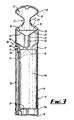
Figure 1 is a sectioned front view of a bin according to a first embodiment of the present invention; -
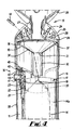
Figure 2 is a sectioned side view of the bin offigure 1 ; -
Figure 3 is a cut-away side view of the bin offigures 1 and 2 ; -
Figure 4 is a cut-away perspective view of a part of the bin offigures 1 to 3 ; -
Figure 5 is a sectioned front view of a bin not according to an embodiment of the present invention but which shares many features with bins according to the present invention; -
Figure 6 is a sectioned side view of the bin offigure 5 ; -
Figure 7 is a sectioned front view of a bin not according to an embodiment of the present invention but which shares many features with bins according to the present invention; -
Figure 8 is a sectioned side view of the bin offigure 7 ; -
Figure 9 is a sectioned front view of a bin, according to a second embodiment of the present invention; -
Figure 10 is a sectioned side view of the bin offigure 9 ; -
Figure 11 is a perspective view of a funnel forming part of the bin offigures 9 and 10 ; -
Figure 12 is a top view of the funnel offigure 11 ; and -
Figure 13 is a sectioned side view of the funnel offigure 12 . - Referring now to
figures 1 to 4 , the exemplary embodiment of a cigarette bin according to a first embodiment of the present invention has a substantially cylindricalouter housing 10 which is hollow and defines a largermain chamber 11 and a smallerupper chamber 12 which are separated by a narrowedregion 13. Thehousing 10 is may be manufactured from any appropriate material, such as a moulded plastics material or a suitable metal. - A
container 14 is supported within themain chamber 11 on ashelf 15 which is integrally formed with abase 16 of thehousing 10. Thecontainer 14 is, for example, manufactured from a folded sheet of mild steel that has a zinc coating. Thecontainer 14 comprises a substantially cylindrical continuousupright wall 14a which extends upwardly from abase plate 14b that rests on theshelf 15. The upper edge or rim of theupright container wall 14a defines anopening 17 disposed in a substantially horizontal plane for receipt of discarded waste. Thecontainer opening 17 is partially closed by a hollowconical guide 18 which serves to guide waste, such as acigarette 19, into thecontainer 14 once discarded into the bin. Theconical guide 18 depicted infigures 1 to 4 has a cone angle, i.e, the angle separating diametrically opposed surfaces, of around 85°, but it will be appreciated that any suitable cone angle may be used. Alower surface 20 of theconical guide 18 is arranged so as to act as a baffle to limit the egress of any smoke from theopening 17 of thecontainer 14. In this way, the smoke is recirculated within the container so as to smother the developing fire. Alower edge 21 of theconical guide 18 is pivotally connected via aplate 22 to ahinge 23 mounted to the rim of thecontainer wall 14a. In this way, in normal use, i.e. when the bin is standing upright for receipt of waste (as depicted infigures 1 to 4 ), theconical guide 18 is located within thecontainer 14 in such a way as to partially close thecontainer opening 17, but when it is desired to empty the contents of the bin by removing thecontainer 14 from thehousing 10 and turning it upside down, theconical guide 18 pivots out from within thecontainer 14 and thereby no longer restricts thecontainer opening 17. - The narrowed
region 13 of thehousing 10 is defined by a rearwardly and upwardlyinclined opening 24 that is closed by ametallic fascia panel 25 and a vertically adjacent forwardly and upwardlyinclined wall portion 26 that meets thefascia panel 25 at acurved wall section 27. Thefascia 25 defines threeapertures 28 and anadjacent stubber grille 29 by which a cigarette or the like may be extinguished before being discarded into the bin through one of theapertures 28. - A
funnel 30 is supported within thehousing 10 just below theapertures 28 and serves to guide cigarettes discarded into the bin through acentral opening 31 down acylindrical chute 32 on to the inclinedupper surface 33 of theconical guide 18. Thefunnel 30 is coaxially or concentrically aligned with theconical guide 18 such that waste exiting thefunnel 30 via thechute 32 is generally guided onto the apex of theconical guide 18. Alower surface 34 of thefunnel 30 is arranged so as to act as a baffle to shield theapertures 28 andstubber grilles 29 from any smoke that might egress from the restrictedopening 17 of thecontainer 14. As an additional safety feature, any smoke egressing from thecontainer opening 17 which manages to pass thechute 32 and thefunnel 30, can be received within theupper chamber 12 of thehousing 10 and then recirculated back down to thecontainer 14 via thefunnel 30 and thechute 32 to aid extinguishing of the smouldering waste. The relative positioning of anupper surface 35 of thefunnel 30 relative to theapertures 28 andstubber grilles 29 restricts the ingress of air from the surroundings into the interior of thehousing 10 or thecontainer 14. Anupper rim 36 of thefunnel 30 is provided with a laterally extendingflange 37 which is used to connect the funnel to thehousing 10. - The
housing 10 is provided with adoor 38 that is pivotally moveable relative to themain chamber 11 of thehousing 10 to provide access to thecontainer 14. Alocking mechanism 39 serves to lock the bin in a closed position (as depicted infigures 1 to 4 ) and comprises ametallic bar 40 rotatably supported on ashaft 41. When the bin is locked in the closed position anend portion 42 of themetallic bar 40 is received in acomplementary recess 43 defined by thebin housing 10. In order to open the bin, theshaft 41 is rotated so as to release theend portion 42 of thebar 40 from therecess 43. Rotation of theshaft 41 is accomplished by engagement of an exposedouter end 44 of theshaft 41 with a specially adapted tool (not shown). Thedoor 38 can then be pivoted forwards and downwards to provide access to thecontainer 14, which can then be removed from theshelf 15 and emptied by inverting it and allowing theconical guide 18 to pivot away from thecontainer opening 17. - The
container 14 is supported on theshelf 15 by means of a disc ofmagnetic material 45 connected to thehousing 10. Thedisc 45 magnetically attracts theupright sidewall 14a of thecontainer 14 and serves to prevent thecontainer 14 from moving during opening of thedoor 38 of thehousing 10. Thedisc 45 also prevents thecontainer 14 from being disturbed during opening of the bin in windy conditions. It will be appreciated that any size and shape of magnet may be used as appropriate. The magnet may be retained in a casing and inserted into a back plate of thehousing 10. - The structure of the bin is designed to hinder or extinguish any fires present in the
bin container 14. It will be appreciated that this is achieved primarily by the provision of the upper andlower guides container 14 and serve as baffles to restrict the ingress of air from the surrounding, which might otherwise support combustion within thecontainer 14 and substantially prevent the egress of smoke from smouldering waste contained within thecontainer 14. The bin structure also ensures that the debris from cigarettes and the like is retained in an efficient manner and also serves to facilitate the emptying process as described above. - An example of a bin not in accordance with the present invention but which shares many features with bins according to the invention is depicted in
figures 5 and 6 where, for ease of preference, similar reference numbers are used to refer to components which are similar to those of the embodiment depicted infigures 1 to 4 , save for being increased by 100. The primary difference between the bin shown infigures 1 to 4 and the bin shown infigures 5 and 6 is the size, shape and positioning of the lowerconical guide 118. Infigures 5 and 6 , theconical guide 118 is radially smaller, with a more acute cone angle. Theconical guide 118 is also suspended from a lower end of thefunnel 130 by a pair ofarms 146 which depend downwardly from thefunnel 130 rather than being connected to the upper rim of thecontainer 114. The final difference is that theconical guide 118 is disposed above thecontainer 114 rather than being received within thecontainer 114. It is because of this positioning of theconical guide 118 relative to thecontainer 114 that theconical guide 118 must be radially smaller and possesses a more acute cone angle to ensure that waste striking the upperinclined surface 133 of theconical guide 118 is guided into thecontainer 114. - Another example of a bin not in accordance with the present invention but which shares many features with bins according to the invention is depicted in
figures 7 and 8 where, once again, similar reference numbers are used to refer to components which are similar to those of the embodiment depicted infigures 1 to 4 , save for being increased by 200. The bin shown infigures 7 and 8 is similar to the bin depicted infigures 5 and 6 , however, infigures 7 and 8 theconical guide 218 is radially larger, and has the same cone angle (85°) as that of theconical guide 18 of the first embodiment infigures 1 to 4 . The other difference of note between the bin offigures 7 and 8 and the bin offigures 5 and 6 is that theconical guide 218 of the bin shown infigures 7 and 8 is positioned more closely to the opening 217 of thecontainer 214. - A second embodiment of the bin of the present invention is depicted in
figures 9 and 10 , with a more detailed view of components of this bin being shown infigures 11 to 13 . Infigures 9 to 14 , similar reference numbers are once again used to refer to components which are similar to those of the embodiment depicted infigures 1 to 4 , save for being increased by 300. The second embodiment is similar to the first embodiment depicted infigures 1 to 4 , however, in the second embodiment thecylindrical chute 332 is radially larger than thecylindrical chute 32 in the first embodiment. The cone angle of thefunnel 330 in the second embodiment is around 86°. The other difference of note between the second embodiment and the first embodiment is that theconical guide 318 of the second embodiment, while still being provided adjacent to theopening 317 of thecontainer 314, is provided further below the upper edge or rim of theupright container wall 314a and is therefore positioned lower with respect to thecontainer 314 than theconical guide 18 in the first embodiment. - Numerous modifications and variations to the embodiment described above may be made without departing from the scope of the invention as defined in the appended claims. For example, the exact size and shape of the upper and/or lower guide, i.e. the funnel and the cone, may be varied. In an alternative embodiment both guides may be attached to the container. Finally, the bin may be designed to be wall-mounted rather than free-standing.
Claims (13)
- A bin for the disposal of cigarette waste or the like, comprising a housing (10; 310) defining a chamber (11; 311) and a container (14; 314) received in said chamber (11; 311) for retention of discarded waste, the housing (10; 310) defining at least one aperture (24; 324) through which waste can be discarded for receipt in said container (14; 314), the bin further comprising a downwardly-extending funnel (30; 330) disposed within the housing (10; 310) below the aperture (24; 324), said funnel (30; 330) defining an opening (31; 331) and being configured to guide waste via said opening (31; 331) onto a lower downwardly-inclined waste guide (18; 318) configured to guide waste into the container (14; 314), said lower waste guide (18; 318) being disposed in or adjacent to an opening (17; 317) of the container (14; 314), said funnel (30; 330) and lower waste guide (18; 318) being configured so as to restrict the ingress of oxygen via the aperture (24; 324) into the container (14; 314) and the egress of smoke from burning waste retained within the container (14; 314) to the aperture (24; 324) such that said smoke is recirculated within the bin chamber (11; 311) and thereby helps to extinguish said burning waste; characterised in that the lower waste guide (18; 318) is pivotally connected to the container (14; 314) so as to be moveable between a first position in which the container opening (17; 317) is restricted and a second position in which the container opening (17; 317) is less restricted so as to facilitate emptying of waste from the container (14; 314).
- A bin according to claim 1, wherein the lower waste guide (18; 3 x 8) is disposed within the container (14; 314) when the bin is arranged to retain waste.
- A bin according to claim 1 or 2, wherein the lower waste guide (18; 318) comprises two downwardly inclined surfaces connected at their upper edges or a conical portion.
- A bin according to claim 3, wherein said two surfaces or said conical portion define(s) a space underneath said inclined surfaces or said conical portion respectively which faces into the container (14; 314).
- A bin according to claim 3 or 4, wherein said funnel opening (31; 331) is disposed above the apex of the two connected surfaces or the conical portion of the lower waste guide (18; 318).
- A bin according to any preceding claim, wherein a chute (32; 332) depends downwardly from the funnel (30; 330) so as to guide waste from said funnel opening (31; 331) to the lower waste guide (18; 318).
- A bin according to any preceding claim, wherein the lower waste guide (18; 318) is connected to an upper rim of the container (14; 314) which defines the opening (17; 317) of the container (14; 314).
- A bin according to any preceding claim, wherein the lower waste guide (18; 318) is connected to the container (14; 314) via a lowermost edge (21; 321) of the lower waste guide (18; 318).
- A bin according to any preceding claim, wherein the tunnel (30; 330) is connected to the bin housing (10; 310).
- A bin according to claim 9, wherein the funnel (30; 330) is connected to the housing (10; 310) via a flange (37; 337) extending from an upper rim (36; 336) of the funnel (30; 330).
- A bin according to any preceding claim, wherein the housing (10; 310) defines a further chamber (12; 312) located above the chamber (11; 311) which receives the container (14; 314).
- A, bin according to claim 11, wherein said further chamber (12; 312) provides a volume for receipt of smoke egressing the container (14; 314), such that said smoke can be recirculated to the container (14; 314) to help extinguish said burning waste.
- A bin according to claim 11 or 12, wherein the housing (10; 310) defines a narrowed passage (13; 313) between said further chamber (12; 312) and the chamber (11; 311) which receives the container (14; 314).
Applications Claiming Priority (2)
| Application Number | Priority Date | Filing Date | Title |
|---|---|---|---|
| GB0706986A GB0706986D0 (en) | 2007-04-11 | 2007-04-11 | A Bin |
| GB0709955A GB0709955D0 (en) | 2007-05-23 | 2007-05-23 | A bin |
Publications (2)
| Publication Number | Publication Date |
|---|---|
| EP1980164A1 EP1980164A1 (en) | 2008-10-15 |
| EP1980164B1 true EP1980164B1 (en) | 2011-09-07 |
Family
ID=39431002
Family Applications (1)
| Application Number | Title | Priority Date | Filing Date |
|---|---|---|---|
| EP08251335A Active EP1980164B1 (en) | 2007-04-11 | 2008-04-05 | A bin |
Country Status (3)
| Country | Link |
|---|---|
| EP (1) | EP1980164B1 (en) |
| AT (1) | ATE523098T1 (en) |
| GB (1) | GB2448416B (en) |
Families Citing this family (2)
| Publication number | Priority date | Publication date | Assignee | Title |
|---|---|---|---|---|
| CN106865065A (en) * | 2017-04-27 | 2017-06-20 | 王兴莉 | A kind of new sharp disposable container |
| CN108001916B (en) * | 2017-12-30 | 2024-03-08 | 北控城市服务投资(中国)集团有限公司 | Cigarette end extinguishing device |
Family Cites Families (10)
| Publication number | Priority date | Publication date | Assignee | Title |
|---|---|---|---|---|
| BE351298A (en) * | 1928-04-19 | |||
| US1719925A (en) * | 1928-10-05 | 1929-07-09 | American Auto Lamp Co Inc | Smoker's receptacle |
| US2716414A (en) * | 1952-01-14 | 1955-08-30 | Nels H Nelson | Tobacco ash receptacle |
| US2797136A (en) * | 1953-10-14 | 1957-06-25 | Nels H Nelson | Disappearing ash receptacle |
| US2962181A (en) * | 1957-11-18 | 1960-11-29 | Nels H Nelson | Tobacco ash receptacle |
| FR2398467A1 (en) * | 1977-07-25 | 1979-02-23 | Espinos Paul | Automatic ashtray which distributes ash etc. - has collector cover and enclosed vessel with deflector mass |
| DE3529254A1 (en) * | 1984-08-16 | 1986-02-27 | Viel, Paul, 6800 Mannheim | Ash tray |
| JPH0928368A (en) * | 1995-07-25 | 1997-02-04 | Mitsuo Kinzoku Kogyo Kk | Dry type cigarette butt extinguishing receptacle |
| JP3353192B2 (en) * | 1995-08-01 | 2002-12-03 | ミツオ金属工業株式会社 | Butt receiver by dry fire extinguishing method |
| JPH09206059A (en) * | 1995-11-30 | 1997-08-12 | Nomura Sangyo Kk | Cigarette butt holder |
-
2008
- 2008-04-05 AT AT08251335T patent/ATE523098T1/en not_active IP Right Cessation
- 2008-04-05 EP EP08251335A patent/EP1980164B1/en active Active
- 2008-04-10 GB GB0806528A patent/GB2448416B/en not_active Expired - Fee Related
Also Published As
| Publication number | Publication date |
|---|---|
| GB0806528D0 (en) | 2008-05-14 |
| GB2448416A (en) | 2008-10-15 |
| EP1980164A1 (en) | 2008-10-15 |
| ATE523098T1 (en) | 2011-09-15 |
| GB2448416B (en) | 2011-12-07 |
Similar Documents
| Publication | Publication Date | Title |
|---|---|---|
| AU713750B2 (en) | Collection device for smoking debris | |
| US7055714B2 (en) | Smoking-waste receptacle | |
| WO2005089577A1 (en) | A portable container for holding waste materials | |
| CN101522062A (en) | Smoking waste receptacle | |
| EP1980164B1 (en) | A bin | |
| US5601095A (en) | Cigarette disposal bin | |
| US4126241A (en) | Rubbish receptacle | |
| JP2649780B2 (en) | Cigarette case | |
| US6626322B1 (en) | Receptacle for spent smoking materials | |
| EP1972214B1 (en) | A bin | |
| GB2100114A (en) | Waste bin | |
| JPH05211923A (en) | Refuse receptacle | |
| US2637490A (en) | Cigarette chute | |
| US6971538B2 (en) | Receptacle | |
| US1988736A (en) | Ash receptacle | |
| CN218464526U (en) | Garbage bin with cigarette end cigarette ash classification collection module | |
| US3406813A (en) | Ash trays | |
| CN212922972U (en) | Cigarette extinguishing sanitation garbage can convenient to throw | |
| WO2022156011A1 (en) | Quick smoke-extinguishing ashtray | |
| KR102561176B1 (en) | Lighter | |
| CN213246903U (en) | Novel ashtray | |
| WO1992020597A1 (en) | A litter bin | |
| GB2282520A (en) | A cigarette disposal bin | |
| KR960003546Y1 (en) | Ash-tray having a sanitary treatment device | |
| KR200172166Y1 (en) | Ash tray |
Legal Events
| Date | Code | Title | Description |
|---|---|---|---|
| PUAI | Public reference made under article 153(3) epc to a published international application that has entered the european phase |
Free format text: ORIGINAL CODE: 0009012 |
|
| AK | Designated contracting states |
Kind code of ref document: A1 Designated state(s): AT BE BG CH CY CZ DE DK EE ES FI FR GB GR HR HU IE IS IT LI LT LU LV MC MT NL NO PL PT RO SE SI SK TR |
|
| AX | Request for extension of the european patent |
Extension state: AL BA MK RS |
|
| 17P | Request for examination filed |
Effective date: 20090209 |
|
| 17Q | First examination report despatched |
Effective date: 20090313 |
|
| AKX | Designation fees paid |
Designated state(s): AT BE BG CH CY CZ DE DK EE ES FI FR GB GR HR HU IE IS IT LI LT LU LV MC MT NL NO PL PT RO SE SI SK TR |
|
| GRAP | Despatch of communication of intention to grant a patent |
Free format text: ORIGINAL CODE: EPIDOSNIGR1 |
|
| GRAS | Grant fee paid |
Free format text: ORIGINAL CODE: EPIDOSNIGR3 |
|
| GRAA | (expected) grant |
Free format text: ORIGINAL CODE: 0009210 |
|
| REG | Reference to a national code |
Ref country code: GB Ref legal event code: FG4D |
|
| REG | Reference to a national code |
Ref country code: CH Ref legal event code: EP |
|
| REG | Reference to a national code |
Ref country code: IE Ref legal event code: FG4D |
|
| REG | Reference to a national code |
Ref country code: DE Ref legal event code: R096 Ref document number: 602008009516 Country of ref document: DE Effective date: 20111103 |
|
| REG | Reference to a national code |
Ref country code: NL Ref legal event code: VDEP Effective date: 20110907 |
|
| PG25 | Lapsed in a contracting state [announced via postgrant information from national office to epo] |
Ref country code: NO Free format text: LAPSE BECAUSE OF FAILURE TO SUBMIT A TRANSLATION OF THE DESCRIPTION OR TO PAY THE FEE WITHIN THE PRESCRIBED TIME-LIMIT Effective date: 20111207 Ref country code: SE Free format text: LAPSE BECAUSE OF FAILURE TO SUBMIT A TRANSLATION OF THE DESCRIPTION OR TO PAY THE FEE WITHIN THE PRESCRIBED TIME-LIMIT Effective date: 20110907 Ref country code: LT Free format text: LAPSE BECAUSE OF FAILURE TO SUBMIT A TRANSLATION OF THE DESCRIPTION OR TO PAY THE FEE WITHIN THE PRESCRIBED TIME-LIMIT Effective date: 20110907 Ref country code: FI Free format text: LAPSE BECAUSE OF FAILURE TO SUBMIT A TRANSLATION OF THE DESCRIPTION OR TO PAY THE FEE WITHIN THE PRESCRIBED TIME-LIMIT Effective date: 20110907 Ref country code: HR Free format text: LAPSE BECAUSE OF FAILURE TO SUBMIT A TRANSLATION OF THE DESCRIPTION OR TO PAY THE FEE WITHIN THE PRESCRIBED TIME-LIMIT Effective date: 20110907 |
|
| LTIE | Lt: invalidation of european patent or patent extension |
Effective date: 20110907 |
|
| PG25 | Lapsed in a contracting state [announced via postgrant information from national office to epo] |
Ref country code: CY Free format text: LAPSE BECAUSE OF FAILURE TO SUBMIT A TRANSLATION OF THE DESCRIPTION OR TO PAY THE FEE WITHIN THE PRESCRIBED TIME-LIMIT Effective date: 20110907 Ref country code: LV Free format text: LAPSE BECAUSE OF FAILURE TO SUBMIT A TRANSLATION OF THE DESCRIPTION OR TO PAY THE FEE WITHIN THE PRESCRIBED TIME-LIMIT Effective date: 20110907 Ref country code: SI Free format text: LAPSE BECAUSE OF FAILURE TO SUBMIT A TRANSLATION OF THE DESCRIPTION OR TO PAY THE FEE WITHIN THE PRESCRIBED TIME-LIMIT Effective date: 20110907 Ref country code: GR Free format text: LAPSE BECAUSE OF FAILURE TO SUBMIT A TRANSLATION OF THE DESCRIPTION OR TO PAY THE FEE WITHIN THE PRESCRIBED TIME-LIMIT Effective date: 20111208 Ref country code: AT Free format text: LAPSE BECAUSE OF FAILURE TO SUBMIT A TRANSLATION OF THE DESCRIPTION OR TO PAY THE FEE WITHIN THE PRESCRIBED TIME-LIMIT Effective date: 20110907 |
|
| REG | Reference to a national code |
Ref country code: AT Ref legal event code: MK05 Ref document number: 523098 Country of ref document: AT Kind code of ref document: T Effective date: 20110907 |
|
| PG25 | Lapsed in a contracting state [announced via postgrant information from national office to epo] |
Ref country code: BE Free format text: LAPSE BECAUSE OF FAILURE TO SUBMIT A TRANSLATION OF THE DESCRIPTION OR TO PAY THE FEE WITHIN THE PRESCRIBED TIME-LIMIT Effective date: 20110907 |
|
| PG25 | Lapsed in a contracting state [announced via postgrant information from national office to epo] |
Ref country code: IS Free format text: LAPSE BECAUSE OF FAILURE TO SUBMIT A TRANSLATION OF THE DESCRIPTION OR TO PAY THE FEE WITHIN THE PRESCRIBED TIME-LIMIT Effective date: 20120107 Ref country code: CZ Free format text: LAPSE BECAUSE OF FAILURE TO SUBMIT A TRANSLATION OF THE DESCRIPTION OR TO PAY THE FEE WITHIN THE PRESCRIBED TIME-LIMIT Effective date: 20110907 Ref country code: SK Free format text: LAPSE BECAUSE OF FAILURE TO SUBMIT A TRANSLATION OF THE DESCRIPTION OR TO PAY THE FEE WITHIN THE PRESCRIBED TIME-LIMIT Effective date: 20110907 |
|
| PG25 | Lapsed in a contracting state [announced via postgrant information from national office to epo] |
Ref country code: PL Free format text: LAPSE BECAUSE OF FAILURE TO SUBMIT A TRANSLATION OF THE DESCRIPTION OR TO PAY THE FEE WITHIN THE PRESCRIBED TIME-LIMIT Effective date: 20110907 Ref country code: IT Free format text: LAPSE BECAUSE OF FAILURE TO SUBMIT A TRANSLATION OF THE DESCRIPTION OR TO PAY THE FEE WITHIN THE PRESCRIBED TIME-LIMIT Effective date: 20110907 Ref country code: RO Free format text: LAPSE BECAUSE OF FAILURE TO SUBMIT A TRANSLATION OF THE DESCRIPTION OR TO PAY THE FEE WITHIN THE PRESCRIBED TIME-LIMIT Effective date: 20110907 Ref country code: PT Free format text: LAPSE BECAUSE OF FAILURE TO SUBMIT A TRANSLATION OF THE DESCRIPTION OR TO PAY THE FEE WITHIN THE PRESCRIBED TIME-LIMIT Effective date: 20120109 Ref country code: NL Free format text: LAPSE BECAUSE OF FAILURE TO SUBMIT A TRANSLATION OF THE DESCRIPTION OR TO PAY THE FEE WITHIN THE PRESCRIBED TIME-LIMIT Effective date: 20110907 Ref country code: EE Free format text: LAPSE BECAUSE OF FAILURE TO SUBMIT A TRANSLATION OF THE DESCRIPTION OR TO PAY THE FEE WITHIN THE PRESCRIBED TIME-LIMIT Effective date: 20110907 |
|
| PLBE | No opposition filed within time limit |
Free format text: ORIGINAL CODE: 0009261 |
|
| STAA | Information on the status of an ep patent application or granted ep patent |
Free format text: STATUS: NO OPPOSITION FILED WITHIN TIME LIMIT |
|
| PG25 | Lapsed in a contracting state [announced via postgrant information from national office to epo] |
Ref country code: DK Free format text: LAPSE BECAUSE OF FAILURE TO SUBMIT A TRANSLATION OF THE DESCRIPTION OR TO PAY THE FEE WITHIN THE PRESCRIBED TIME-LIMIT Effective date: 20110907 |
|
| 26N | No opposition filed |
Effective date: 20120611 |
|
| REG | Reference to a national code |
Ref country code: DE Ref legal event code: R097 Ref document number: 602008009516 Country of ref document: DE Effective date: 20120611 |
|
| PG25 | Lapsed in a contracting state [announced via postgrant information from national office to epo] |
Ref country code: MC Free format text: LAPSE BECAUSE OF NON-PAYMENT OF DUE FEES Effective date: 20120430 |
|
| REG | Reference to a national code |
Ref country code: CH Ref legal event code: PL |
|
| REG | Reference to a national code |
Ref country code: IE Ref legal event code: MM4A |
|
| REG | Reference to a national code |
Ref country code: FR Ref legal event code: ST Effective date: 20121228 |
|
| PG25 | Lapsed in a contracting state [announced via postgrant information from national office to epo] |
Ref country code: CH Free format text: LAPSE BECAUSE OF NON-PAYMENT OF DUE FEES Effective date: 20120430 Ref country code: IE Free format text: LAPSE BECAUSE OF NON-PAYMENT OF DUE FEES Effective date: 20120405 Ref country code: LI Free format text: LAPSE BECAUSE OF NON-PAYMENT OF DUE FEES Effective date: 20120430 |
|
| REG | Reference to a national code |
Ref country code: DE Ref legal event code: R119 Ref document number: 602008009516 Country of ref document: DE Effective date: 20121101 |
|
| PG25 | Lapsed in a contracting state [announced via postgrant information from national office to epo] |
Ref country code: FR Free format text: LAPSE BECAUSE OF NON-PAYMENT OF DUE FEES Effective date: 20120430 |
|
| PG25 | Lapsed in a contracting state [announced via postgrant information from national office to epo] |
Ref country code: ES Free format text: LAPSE BECAUSE OF FAILURE TO SUBMIT A TRANSLATION OF THE DESCRIPTION OR TO PAY THE FEE WITHIN THE PRESCRIBED TIME-LIMIT Effective date: 20111218 |
|
| PG25 | Lapsed in a contracting state [announced via postgrant information from national office to epo] |
Ref country code: BG Free format text: LAPSE BECAUSE OF FAILURE TO SUBMIT A TRANSLATION OF THE DESCRIPTION OR TO PAY THE FEE WITHIN THE PRESCRIBED TIME-LIMIT Effective date: 20111207 |
|
| PG25 | Lapsed in a contracting state [announced via postgrant information from national office to epo] |
Ref country code: MT Free format text: LAPSE BECAUSE OF FAILURE TO SUBMIT A TRANSLATION OF THE DESCRIPTION OR TO PAY THE FEE WITHIN THE PRESCRIBED TIME-LIMIT Effective date: 20110907 |
|
| REG | Reference to a national code |
Ref country code: GB Ref legal event code: 732E Free format text: REGISTERED BETWEEN 20130829 AND 20130904 |
|
| PG25 | Lapsed in a contracting state [announced via postgrant information from national office to epo] |
Ref country code: TR Free format text: LAPSE BECAUSE OF FAILURE TO SUBMIT A TRANSLATION OF THE DESCRIPTION OR TO PAY THE FEE WITHIN THE PRESCRIBED TIME-LIMIT Effective date: 20110907 |
|
| PG25 | Lapsed in a contracting state [announced via postgrant information from national office to epo] |
Ref country code: LU Free format text: LAPSE BECAUSE OF NON-PAYMENT OF DUE FEES Effective date: 20120405 |
|
| PG25 | Lapsed in a contracting state [announced via postgrant information from national office to epo] |
Ref country code: HU Free format text: LAPSE BECAUSE OF FAILURE TO SUBMIT A TRANSLATION OF THE DESCRIPTION OR TO PAY THE FEE WITHIN THE PRESCRIBED TIME-LIMIT Effective date: 20080405 |
|
| PG25 | Lapsed in a contracting state [announced via postgrant information from national office to epo] |
Ref country code: DE Free format text: LAPSE BECAUSE OF FAILURE TO SUBMIT A TRANSLATION OF THE DESCRIPTION OR TO PAY THE FEE WITHIN THE PRESCRIBED TIME-LIMIT Effective date: 20121101 |
|
| PGFP | Annual fee paid to national office [announced via postgrant information from national office to epo] |
Ref country code: GB Payment date: 20240418 Year of fee payment: 17 |