EP1980130B1 - Locating and routing a call - Google Patents
Locating and routing a call Download PDFInfo
- Publication number
- EP1980130B1 EP1980130B1 EP07730890.6A EP07730890A EP1980130B1 EP 1980130 B1 EP1980130 B1 EP 1980130B1 EP 07730890 A EP07730890 A EP 07730890A EP 1980130 B1 EP1980130 B1 EP 1980130B1
- Authority
- EP
- European Patent Office
- Prior art keywords
- location
- call
- routing
- terminal
- subsystem
- Prior art date
- Legal status (The legal status is an assumption and is not a legal conclusion. Google has not performed a legal analysis and makes no representation as to the accuracy of the status listed.)
- Active
Links
- 230000000977 initiatory effect Effects 0.000 claims description 23
- 238000000034 method Methods 0.000 claims description 13
- 238000004590 computer program Methods 0.000 claims 1
- 230000007246 mechanism Effects 0.000 description 5
- 230000004807 localization Effects 0.000 description 4
- 230000005540 biological transmission Effects 0.000 description 3
- 230000001413 cellular effect Effects 0.000 description 3
- 238000007726 management method Methods 0.000 description 3
- 108010007100 Pulmonary Surfactant-Associated Protein A Proteins 0.000 description 2
- 102100027773 Pulmonary surfactant-associated protein A2 Human genes 0.000 description 2
- 238000006243 chemical reaction Methods 0.000 description 2
- 238000004891 communication Methods 0.000 description 2
- 238000012795 verification Methods 0.000 description 2
- 238000006677 Appel reaction Methods 0.000 description 1
- 235000021183 entrée Nutrition 0.000 description 1
- GVVPGTZRZFNKDS-JXMROGBWSA-N geranyl diphosphate Chemical compound CC(C)=CCC\C(C)=C\CO[P@](O)(=O)OP(O)(O)=O GVVPGTZRZFNKDS-JXMROGBWSA-N 0.000 description 1
- 230000001960 triggered effect Effects 0.000 description 1
Images

Classifications
-
- H—ELECTRICITY
- H04—ELECTRIC COMMUNICATION TECHNIQUE
- H04W—WIRELESS COMMUNICATION NETWORKS
- H04W8/00—Network data management
- H04W8/02—Processing of mobility data, e.g. registration information at HLR [Home Location Register] or VLR [Visitor Location Register]; Transfer of mobility data, e.g. between HLR, VLR or external networks
- H04W8/08—Mobility data transfer
- H04W8/10—Mobility data transfer between location register and external networks
-
- H—ELECTRICITY
- H04—ELECTRIC COMMUNICATION TECHNIQUE
- H04W—WIRELESS COMMUNICATION NETWORKS
- H04W4/00—Services specially adapted for wireless communication networks; Facilities therefor
- H04W4/02—Services making use of location information
- H04W4/029—Location-based management or tracking services
-
- H—ELECTRICITY
- H04—ELECTRIC COMMUNICATION TECHNIQUE
- H04W—WIRELESS COMMUNICATION NETWORKS
- H04W4/00—Services specially adapted for wireless communication networks; Facilities therefor
- H04W4/02—Services making use of location information
-
- H—ELECTRICITY
- H04—ELECTRIC COMMUNICATION TECHNIQUE
- H04W—WIRELESS COMMUNICATION NETWORKS
- H04W4/00—Services specially adapted for wireless communication networks; Facilities therefor
- H04W4/90—Services for handling of emergency or hazardous situations, e.g. earthquake and tsunami warning systems [ETWS]
-
- H—ELECTRICITY
- H04—ELECTRIC COMMUNICATION TECHNIQUE
- H04W—WIRELESS COMMUNICATION NETWORKS
- H04W76/00—Connection management
- H04W76/50—Connection management for emergency connections
Definitions
- the present invention relates to the field of telecommunications, and more particularly to the implementation of telecommunications services based on call routing and call location.
- Some telecommunications systems offer a service based on the location of a caller. This is particularly the case for services adapted to handle emergency calls, or even for certain delivery services which, depending on information relating to the call received, are adapted to determine the place of delivery to the home of the person. 'calling for example.
- telecommunications systems include a call center for handling this type of call.
- a call center for handling this type of call.
- the caller On receipt of an emergency call, such a call center is conventionally able to provide assistance to the caller.
- the caller is generally located in order to be able, if necessary, to send him this assistance to the location where he is.
- it is important to establish communication with the caller and locate the caller.
- Such systems are suitable to provide an emergency service which can be defined by routing an emergency call to a call center (or LER for 'Location Enabled Routing'), and transmission of caller location information to this call center (or LIP for 'Location Information Presentation').
- Certain standards define certain characteristics of this type of emergency services, such as for example the standards defined in Europe by the CGALIES group (for 'Coordination Group on Access to Location Information by Emergency Services').
- a geographic area identifier relating to the first switch that supports the initiated call allows the call to be redirected to the appropriate call center to handle the emergency call.
- the call can thus be routed to a call center from which the caller is easily accessible.
- the location of the caller is based on an association recorded between the subscriber number of the caller and his address, that is to say that the location is carried out from a directory.
- such an implementation is designed for a conventional network architecture of the PSTN type and is not easily transposable to mobile telecommunications networks.
- VoIP Voice over Internet Protocol
- the document 'Emergency call positioning' by Mikka Poikselhim proposes an implementation of an emergency service in a mobile telecommunications system based on a circuit switched network or on a packet switched network.
- This document proposes to implement an emergency service in an IMS type network, for “Internet protocol Multimedia Subsystem”, as defined by 3GPP, in particular in document TR 23.867.
- the caller location step is performed by a location server which can be connected to the S-CSCF entity.
- a terminal connects to this IMS network via a GPRS-type core network, for 'General Packet Radio Service'. Then, the S-CSCF entity requests a location of the caller from a location server.
- Such a solution makes it possible to implement an emergency service in a network architecture comprising a call center connected to the IMS network to which the caller's terminal connects.
- an IMS network is not connected to an emergency call center.
- a terminal initiating an emergency call can connect to an IMS network which is not connected to the emergency call center in charge of managing emergency calls in the geographical area where the terminal is located.
- WO2005004521 deals with emergency calls, which are routed based on the location of a mobile subscriber in a cellular wireless network.
- US2005024265 concerns emergency call routing according to the location of a calling mobile.
- the aforementioned drawbacks relating to an emergency service can be transposed to any other type of telecommunications service which is based, like an emergency service, on call location and call routing to a suitable call center. to provide the service required by the type of call received.
- the terms 'a location function associated with a telecommunications subsystem' mean that the location function considered is a function local to the subsystem with which it is associated, suitable for determining information of location of a terminal located in this subsystem.
- the terms 'a location function adapted to cooperate with the call center' mean that the call center and the location function are adapted to transmit, respectively receive, location information between them.
- an end-to-end call routing and location service can advantageously be provided, in an efficient and rapid manner, to a terminal which is located in a telecommunications subsystem to which the call center in question. charge of the management of calls in the geographical area in which the terminal is located is not connected. Indeed, in such a method, the call is routed to a call center which is connected to the second subsystem, while the terminal connects to the system via the first subsystem.
- such a method offers a routing and call location service in which the step of locating the caller and the step of routing the call are advantageously carried out in parallel with each other. the other at the level of the first telecommunications subsystem.
- the routing of the call can be carried out quickly, without waiting for the realization a step of locating the terminal, such as a step managed in a context of LIP, as previously mentioned.
- the present invention is not limited in the mechanism for associating the call center with the second location function.
- the second location function can make the location information received from the first location function available to the call center.
- the call center can receive this location information when it decides that it needs such information.
- the call center then sends a request to the second location function.
- the second location function transmits the location information to the call center without waiting for a request from it.
- the second location function is a function associated with the second subsystem. It is then determined according to the call center considered.
- this second location function being associated with the second subsystem, and the latter being linked to the call center, this second location function is then adapted to cooperate with the call center via the second subsystem.
- the call center can receive the location information of the calling terminal from the location function of the second subsystem, without knowing the first subsystem, that is to say the subsystem in which the call is initiated.
- a call center can advantageously manage a single interface for the management of calls linked to the service in question, the one which allows it to communicate with the location server with which it cooperates, contrary to what some other architectures impose.
- the second location function is a global location function for the telecommunications system.
- the call center requests location information from the global location function.
- Such a global function makes it possible to centralize the caller location information in the system so as to provide it, if necessary, to the call centers which might need it to provide the call routing and location service. Such centralization of information also makes it possible to provide this information with a view to offering other services in such a telecommunications system.
- this location information can be advantageously based on this location information. Indeed, for example, this location information can be used in the context of emergency call services and in the context of delivery services as set out above, for the same telecommunications system.
- a routing function is adapted to select, based on routing assistance information received from the terminal, a call center to route the initiation message of the call center. 'call.
- this routing function may be common to telecommunications subsystems, and therefore a centralization of information making it possible to select a call center to handle an emergency call may be implemented.
- a centralized database can advantageously be used for other services offered in the system considered.
- routing aid information is determined as a function of the information present in the received call initiation message.
- routing aid information corresponds to information relating to the type of network access, which is indicated in the call initiation message, such as the information indicated in the 'P Access Network Info' field, such as as defined in document RFC 3455 (for 'Request For Comment') which can be inserted by the terminal or by the P-CSCF entity.
- the present invention covers any type of routing based on information included in the call initiation message.
- the terminal identifier can include a call number of the terminal in the telecommunications system, such as a callback number or 'Callback Number'.
- the present invention is described below in its application to a network architecture as defined by 3GPP in the context of IMS type networks.
- 3GPP 3rd Generation Partnership Project
- the I-CSCF 13 and S-CSCF 14 entities can be linked to an HSS server 15 (for "Home Subscriber Server"), which operates as HLR (for "Home Location Register”) and also contains functions relating to the multimedia IP domain.
- HSS server 15 for "Home Subscriber Server”
- HLR for "Home Location Register”
- Such an architecture further comprises an application server, or AS for “Application Server” 16.
- a terminal 11 can connect to the IMS 10 network.
- Emergency call centers 23, or PSAP for 'Public Safety Answering Point' can be linked to such an architecture via a GSTN 18 network, for 'General Switched Telephone Network' or PSTN for 'Public Switched Telephone Network' analog or digital, or even directly via an adapted protocol session of SIP type, for 'Session Initiation Protocol' for example.
- a PSAP emergency call center can also be linked to such an architecture via an NGN type link, for 'Next Generation Networks', that is to say a link according to the IP protocol allowing the transmission of data and of the way.
- the figure 2 illustrates a telecommunications system architecture.
- a first telecommunications subsystem 10, comprising a P-CSCF entity 12 and a S-CSCF entity 14 is linked to a second telecommunications subsystem 20 comprising an S-CSCF entity 24 and a P-CSCF entity 22.
- the first and second subsystems each correspond to an IMS type network such as that described. with reference to the figure 1 and are linked together through the S-CSCF 14 and S-CSCF 24 entities.
- first and second location functions suitable for determining location information of a terminal which is connected in their respective subsystem.
- these first and second location functions are implemented respectively in location servers 21 and 25.
- These location servers can correspond to GMLC network entities for 'Gateway Mobility Location Center'. , as defined in document 3 GPP TS 23.271, or even correspond to a location server entity as described in the OMA / MLP v3.1 standard or any other type of entity capable of determining the location of a user or equipment.
- a terminal location function can be implemented on any network entity of the system.
- a location server can in particular perform authentication functions, verification of subscriptions to the required services, location of users, format conversion of location information according to the service requesting this information.
- the second subsystem 20 is further adapted to cooperate with an emergency call center 23.
- the present invention does not present any limitation as to the type of link between the emergency call center to which a call is routed and the telecommunications network to which this call center is connected.
- the emergency call center can be directly linked via a P-CSCF entity to the second subsystem 20, or it can be linked to the second subsystem via a routing network entity, such as a gateway. for example.
- a routing network entity such as a gateway.
- the steps of routing urgent calls and locating the caller can advantageously be carried out in parallel.
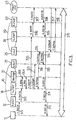
- the figure 3 illustrates an exchange of messages for handling an emergency call in a telecommunications system according to an example. This system is similar to that described above with reference to the figure 2 .
- a terminal 11 initiates an emergency call in the IMS network 10, by sending a call initiation message 301 “INVITE” according to the SIP protocol to the P-CSCF entity 12 of the first subsystem.
- the P-CSCF entity 12 transmits the 'INVITE' message 301 in the form of an 'INVITE' message 302 to the S-CSCF network entity 14.
- the latter is suitable for routing the message according to a determined routing function. to the call center 23.
- a PDP communication context specific to emergency calls is created so as in particular to manage the priority of the messages exchanged during this call. call.
- Such an emergency context is managed at the level of the S-CSCF entity 14.
- this example covers all possible implementations of the routing function implemented at S-CSCF 14 to route the emergency call.
- this routing function can be implemented for example directly on the S-CSCF entity 14, or again on another entity of the IMS network 10. It can for example be implemented on a specific routing entity. It can also be located on a location server, or even on a P-CSCF network entity.
- This routing function can be adapted to manage the routing of emergency calls received in the IMS 10 network exclusively. In this case, this routing function is dedicated to the IMS network 10, or first telecommunications subsystem. This function can also be adapted to manage the routing of emergency calls received both in the IMS 10 and 20 networks. More generally, this routing function can be a global function, common to the two telecommunications subsystems. of the system.
- Such a routing table can be managed by the S-CSCF. It is also possible to provide for this routing table to be managed by any device in the network.
- the present invention can be easily applied to a telecommunications system comprising more than two telecommunications subsystems.
- the routing function can be common to all the telecommunications subsystems of the system considered, that is to say to a set of telecommunications networks over which emergency calls can be transmitted.
- the telecommunications system includes a plurality of emergency call centers.
- the routing function can then advantageously be adapted to manage a list of emergency call centers and to select one of the emergency call centers as a function of routing assistance information received from the calling terminal.
- Such a routing function can in particular take into account an indication of the approximate location of the calling terminal which is included in the call initiation message to be routed. Therefore, the routing function can select the emergency call center closest to the terminal or, at least, from which the calling terminal is most accessible.
- An indication of approximate location included in the call initiation message may correspond, for example, to an identifier of the cell in which the terminal is located, or cellld, or more generally, information relating to the access network, such as a type of access such as for example an access of the IEEE 802.11a type, or even of the 3GPP UTRAN FDD type, accompanied by information on the access such as for example an identifier of the cell in an access of the 3GPP UTRAN type.
- the present invention does not present any limitation as to the mechanism for selecting the call center at the level of the management entity of the routing table.
- the emergency call processing can be carried out efficiently, since the routing function is able on the basis of this indication received in the message. 'call initiation to make a relevant selection of the call center to which to direct the emergency call. Furthermore, such routing can be performed quickly, since the routing function does not wait for a location step to be performed before routing the emergency call. Thus, no significant delay is introduced in such call routing. However, the speed of call processing is a very important characteristic in a telecommunications system offering an emergency service.
- routing function is implemented in a routing entity 31.
- the S-CSCF entity 14 on receipt of the call initiation message 302, requests from the routing function 31 the information useful for routing this message 302. For this purpose, it sends to the routing function a message 303 'Routing Request' and receives from this routing function a message 304 'Routing Response'.
- the S-CSCF entity 14 On receipt of this last message, the S-CSCF entity 14 is able to route the emergency call initiation message to the S-CSCF 24 entity of the second telecommunications subsystem, that is that is to say the IMS network 20, in the form of an “INVITE” message 305 according to the SIP protocol.
- the S-CSCF entity 24 transmits this message to the P-CSCF entity 22 in the form of an “INVITE” message 306 according to the SIP protocol.
- the latter entity 22 finally transmits this emergency call initiation message to the call center 23, in the form of an 'INVITE' message 307 according to the SIP protocol.
- the emergency call is established 319 between the call center 23 and the terminal 11, following the transmission by the emergency call center 23 of a '200 OK' message according to the SIP protocol.
- a message 308 intended for the P-CSCF entity 22 then in the form of a message 309 from the latter entity to the S-CSCF entity 24, then in the form of a message 310 to the S-CSCF entity 14, then in the form of a message 311 to the P-CSCF entity 12 and finally in the form of a message 312 from the latter entity to the terminal 11.
- the emergency call is thus advantageously established without waiting for any step of precise location of the caller to have been performed. Further, by routing on the basis of an approximate location indication, when the call can be routed to a plurality of emergency call centers, one is able to select the call center the most. more appropriate to the treatment of the call initiated according to the accessibility of the caller in relation to the center which will handle this emergency call.
- a caller location step is triggered.
- the S-CSCF entity 14 on receipt of the emergency call initiation message 302, the S-CSCF entity 14 not only initiates a procedure for routing this message to an emergency call center, as described above , but it also launches a procedure for locating the caller by sending a message 313 'locRqst' according for example to a protocol of the MLP type, for 'Mobile Location Protocol' to the location server 21 which is associated with the IMS network 10 .
- this location request message indicates an identifier of the calling terminal, as well as an address of the location server associated with the IMS network 20 to which the emergency call center 23 to which the call is connected is connected. emergency is routed.
- an identifier can be, for example, a call number of the terminal.
- This example covers any method allowing the S-CSCF entity 14 to retrieve the address of the location server associated with the IMS 20 network. For example, provision can be made for such an address to be available from the routing function or even from any other database allowing a location server address to be associated with the selected call center.
- the location server 21 responds to the S-CSCF entity 14 with an acknowledgment message 314 'locResp'.
- the location server 21 determines location information for the terminal 11.
- the location server 21 transmits this information to the location server 25 associated with the IMS network 20 corresponding to the call center to which the emergency call is routed, c ' that is, the second telecommunications subsystem.
- a message 315 'locResp' indicating this location information is sent from the location server 21 to destination of the location server 25.
- a message acknowledging receipt 316 'locResp' of this last message is transmitted in response to the location server 21.
- the step of locating a caller in a telecommunications system is therefore preferably carried out by the location server associated with the IMS network to which the caller is connected, then the location information is transmitted to the location server. associated with the IMS network to which the call center responsible for handling the emergency call is connected.
- the present invention covers all types of architectures in which the emergency call center and the terminal are connected to different subsystems.
- the same emergency call processing mechanisms as those set out above apply in an architecture comprising one or more other subsystems, or other IMS networks, between the IMS network 10 and the IMS network 20.
- the call center may decide to request a precise location of the caller, depending on certain characteristics. of the call, in particular according to the type of assistance to be provided to the caller.
- the emergency call center then transmits a message 317 'locRsqt' to the location server 25 associated with the subsystem to which the emergency call center 23 is connected, in order to request the location information relating to the caller.
- the server 25 sends to the emergency call center 23 a message 318 'locResp' comprising the location information, previously received by the location server 25 from the location server 21 associated with the first. subsystem 10.
- an emergency call is established between the terminal 11 and the emergency call center 23, and on the other hand the latter benefits from precise location information. of the caller so that assistance can be provided effectively.
- the location server 23 In the event that the location server 23 is not able to locating the terminal 11, no location information relating to the terminal is sent to the location server 25. In this context, when the call center requests from the location server 25 location information relating to the terminal 11, this location server 25 determines this location information before transmitting it in response to the emergency call center 23. However, an additional delay is then introduced, which can have significant consequences in the processing of the call. depending on the urgency of the latter.
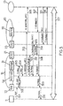
- the figure 4 illustrates an exchange of messages for handling an emergency call in a telecommunications system according to a second example in which the emergency call center to which a call is routed is indirectly connected to the second subsystem telecommunications via a gateway 42.
- This case covers an architecture in which the protocol used in the second telecommunications subsystem is not compatible with the network to which the emergency call center 23 belongs.
- such a gateway corresponds to an MGCF entity, for 'Media Gateway Control Function', as defined for the IMS.
- such a gateway 42 is suitable for carrying out a protocol conversion between the protocol used in the second telecommunications subsystem and the emergency call center 23.
- this gateway 42 is suitable for convert the messages received according to the SIP protocol into messages according to an ISUP type protocol, for 'ISDN User Part'.
- the call initiation message 306 'INVITE' according to the SIP protocol sent by the S-CSCF entity 24 in the second subsystem 20 is received by the gateway 42.
- the latter converts this message according to the SIP protocol into a 307 'IAM' message according to the ISUP protocol and transmits it to the emergency call center.
- the latter responds to message 307 with a 'CONNECT' message 308 according to the ISUP protocol transmitted to the gateway 42.
- the localization step is similar to that described with reference to figure 3 and is therefore not described again.
- the call 319 is established between the terminal 11 and the call center 23 which is connected to the second subsystem 20 by a PSTN network.
- the present invention also finds applications in any system comprising a subsystem corresponding to a cellular mobile network.
- the figure 5 illustrates an exchange of messages for handling an emergency call in such a telecommunications system.
- the first telecommunications subsystem corresponds to a UMTS-type cellular mobile network, for 'Universal Mobile Telecommunications System', comprising a network entity RAN, for 'Radio Access Network', in charge of managing access to terminals and an MSC entity, for 'Mobile Switching Center', in charge of controlling and switching calls.
- a routing function 31 similar to that described with reference to figure 3 above, is associated with this first telecommunications subsystem.
- the terminal 11 initiates an emergency call by sending a message 301 'IAM' according to the ISUP protocol to the RAN entity 53. This message is transmitted to the MSC entity 54. Then, the latter is adapted to route this call according to the routing function 31.
- the same characteristics relating to the routing function as those described above apply in this call context as well.
- the MSC entity 54 obtains from the routing function 31 information allowing it to route this call to the emergency call center 23.
- the message 302 is transmitted to the MSC 55 of the second telecommunications subsystem. 20, in the form of a 305 'IAM' message according to the ISUP protocol.
- the MSC entity 55 transmits this message in the form of a 306 'IAM message to the emergency call center 23.
- the latter responds by sending a 307' CONNECT 'message according to the ISUP protocol, to the MSC 55.
- the latter transmits this message to the MSC 54 in the form of a message 308 'CONNECT'.
- the MSC 54 transmits this message in the form of a message 309 'CONNECT', which finally transmits this last message in the form of a message 310 'CONNECT' according to the ISUP protocol to the terminal 11.
- the MSC entity 54 requests, from a location function 21 associated with the first telecommunications subsystem, a procedure for locating the terminal 11 by sending a message 311 'locRqst' to the location server 21.
- the latter responds to it by acknowledging receipt of this request by sending a message 312 'locRsp'.
- the location server implements a procedure for locating the terminal 11, at the end of which it obtains information on the location of the caller. The latter is then transmitted from this location server 21 to the location server 25 associated with the second telecommunications subsystem by sending a message 313 'location Report'. Then, the location server associated with the second subsystem 20 acknowledges receipt of this information by sending a message 314 'locRsp'.
- the emergency call center 23 can receive the location information from the location server 25, either automatically or on request.
- the first subsystem can correspond to the network to which the terminal is subscribed or even to any other network visited by the terminal during its roaming, or “roaming”.
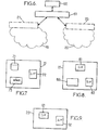
- the figure 6 illustrates a variant of network architecture relating to the implementing a location step according to an embodiment of the present invention.
- a global location server, or a global location function 61 in the telecommunications system according to an embodiment of the present invention is suitable for receiving location information from the terminal 11 from a location server associated with one of the telecommunications subsystems according to an embodiment of the present invention.
- the location server 21 provision can be made for the location server 21 to transmit the location information to the global location server.
- the latter is then able to provide such location information to the call center in charge of the emergency call of the terminal 11.
- a hierarchical architecture makes it possible to centralize the location information of the callers relating to the service. emergency at the level of the global location server.
- the global location function 61 can provide different applications 62 with location information obtained from the location servers of the different subsystems. Indeed, other telecommunications services, other than an emergency call service, can advantageously be based on location information centralized at the level of the global location function.
- the location server 25 associated with the second telecommunications subsystem 20 can easily be replaced by a global location server 61 which receives messages from the location server associated with the first telecommunications subsystem 10 such as the location server 25 and which is adapted to provide, where appropriate, on request or spontaneously, location information to the call center 23.
- the figure 7 illustrates a routing device 31 of a call. It comprises a database 71 which is adapted to manage an association between the routing aid information received in the emergency call initiation message and the call center. It also comprises an interface unit 72 adapted on the one hand to receive a routing information request message of an emergency call and on the other hand to transmit a routing information message indicating the center of the call. 'calls to which to route the emergency call.
- this routing device can be shared for a set of telecommunications subsystems.
- the routing device for PSTN type networks can be implemented by the device which supports UMTS type networks.
- the figure 8 illustrates the location server 21.
- This location server comprises a first interface unit 81 adapted to receive, from the first telecommunications subsystem 10, a request message for the location of a terminal.
- This request message indicates an identifier of the terminal and, where appropriate, another location server suitable for cooperating with the call center. It further comprises a unit 82 for determining information on the location of a terminal as a function of an identifier of the terminal.
- It also comprises a second interface unit 83 adapted to transmit the location information to another location server, if necessary.
- the figure 9 illustrates a global location server.
- the global location server comprises a first interface unit 91 adapted to receive, from a location server 21 of a telecommunications subsystem 10, information on the location of a terminal in said telecommunications subsystem. He also comprises a second interface unit 92 adapted to transmit the location information to the call center.
Description
La présente invention concerne le domaine des télécommunications, et plus particulièrement la mise en œuvre de services de télécommunications basés sur un routage d'appel et une localisation de l'appel.The present invention relates to the field of telecommunications, and more particularly to the implementation of telecommunications services based on call routing and call location.
Certains systèmes de télécommunications offre un service basé sur la localisation d'un appelant. Il en est ainsi notamment pour les services adaptés pour traiter les appels d'urgence, ou encore pour certains services de livraison qui en fonction d'informations relatives à l'appel reçu sont adaptés pour déterminer le lieu d'une livraison au domicile de l'appelant par exemple.Some telecommunications systems offer a service based on the location of a caller. This is particularly the case for services adapted to handle emergency calls, or even for certain delivery services which, depending on information relating to the call received, are adapted to determine the place of delivery to the home of the person. 'calling for example.
Dans le contexte des appels d'urgence, par exemple, les systèmes de télécommunications comprennent un centre d'appels destiné à traiter ce type d'appel. Sur réception d'un appel d'urgence, un tel centre d'appels est classiquement en mesure de prodiguer une aide à l'appelant. A cet effet, l'appelant est généralement localisé afin de pouvoir, le cas échéant, lui faire parvenir cette aide à l'emplacement où il se trouve. Ainsi, dans ce type de système de télécommunications, il est important d'établir une communication avec l'appelant et de localiser l'appelant.In the context of emergency calls, for example, telecommunications systems include a call center for handling this type of call. On receipt of an emergency call, such a call center is conventionally able to provide assistance to the caller. For this purpose, the caller is generally located in order to be able, if necessary, to send him this assistance to the location where he is. Thus, in this type of telecommunications system, it is important to establish communication with the caller and locate the caller.
Pour ce faire, de tels systèmes sont adaptés pour fournir un service d'urgence qui peut être défini par le routage d'un appel d'urgence vers un centre d'appels (ou encore LER pour 'Location Enabled Routing'), et la transmission d'une information de localisation de l'appelant à ce centre d'appels (ou encore LIP pour 'Location Information Presentation').To do this, such systems are suitable to provide an emergency service which can be defined by routing an emergency call to a call center (or LER for 'Location Enabled Routing'), and transmission of caller location information to this call center (or LIP for 'Location Information Presentation').
Certaines normes définissent certaines caractéristiques de ce type de services d'urgence, comme par exemple les normes définies en Europe par le groupe CGALIES (pour 'Coordination Group on Access to Location Information by Emergency Services').Certain standards define certain characteristics of this type of emergency services, such as for example the standards defined in Europe by the CGALIES group (for 'Coordination Group on Access to Location Information by Emergency Services').
Dans les systèmes de télécommunications fixes, tels que ceux basés sur des RTC, pour 'Réseau Téléphonique Public Commuté', un identifiant de zone géographique relatif au premier commutateur qui prend en charge l'appel initié, permet de rediriger l'appel vers le centre d'appels adapté pour traiter l'appel d'urgence. On peut ainsi router l'appel vers un centre d'appels depuis lequel l'appelant est facilement accessible. La localisation de l'appelant se base sur une association enregistrée entre le numéro d'abonné de l'appelant et son adresse, c'est à dire que la localisation est effectuée à partir d'un annuaire. Mais une telle mise en oeuvre est conçue pour une architecture classique de réseau de type RTC et n'est pas aisément transposable à des réseaux de télécommunications mobiles.In fixed telecommunications systems, such as those based on PSTNs, stands for 'Public Switched Telephone Network', a geographic area identifier relating to the first switch that supports the initiated call, allows the call to be redirected to the appropriate call center to handle the emergency call. The call can thus be routed to a call center from which the caller is easily accessible. The location of the caller is based on an association recorded between the subscriber number of the caller and his address, that is to say that the location is carried out from a directory. However, such an implementation is designed for a conventional network architecture of the PSTN type and is not easily transposable to mobile telecommunications networks.
En effet, dans les systèmes de télécommunications mobiles, le numéro de l'appelant ne permet pas de déterminer sa localisation. Il en est de même des systèmes de télécommunications en VoIP (pour 'Voice over Internet Protocol') dans lesquels les utilisateurs peuvent être nomades. Ainsi, dans un tel contexte, le routage de l'appel d'urgence et la localisation de l'appelant sont plus complexes à mettre en œuvre.In fact, in mobile telecommunications systems, the caller's number does not make it possible to determine his location. The same is true of VoIP (Voice over Internet Protocol) telecommunications systems in which users can be nomadic. Thus, in such a context, the routing of the emergency call and the location of the caller are more complex to implement.
Pour ces systèmes de télécommunications mobiles, des spécifications fournies par l'organisme de normalisation 3GPP (pour '3rd Generation Partnership Program') proposent certaines solutions pour la mise en place d'un service d'urgence. Toutefois, de telles spécifications ne détaillent pas une implémentation d'un service d'urgence de bout en bout.For these mobile telecommunications systems, specifications provided by the 3GPP standardization body (for '3rd Generation Partnership Program') propose certain solutions for setting up an emergency service. However, such specifications do not detail an implementation of an end-to-end emergency service.
Le document 'Emergency call positioning' de Mikka Poikselkä, propose une mise en œuvre d'un service d'urgence dans un système de télécommunications mobiles basé sur un réseau à commutation de circuit ou encore sur un réseau à commutation de paquets. Ce document propose d'implémenter un service d'urgence dans un réseau de type IMS, pour 'Internet protocol Multimedia Subsystem', tel que défini par le 3GPP, notamment dans le document TR 23.867. Dans un tel réseau IMS comprenant une entité P-CSCF, pour 'Proxy Call Session Control Function', représentant un premier point de contacts pour les terminaux dans l'IMS, et une entité S-CSCF, pour 'Serving Call Session Control Function', qui est en charge de contrôler les sessions d'un terminal pendant toute la période où ce dernier est enregistré dans l'IMS, l'étape de localisation de l'appelant est réalisée par un serveur de localisation qui peut être relié à l'entité S-CSCF. Dans ce contexte, un terminal se connecte à ce réseau IMS via un réseau cœur de type GPRS, pour 'General Packet Radio Service'. Puis, l'entité S-CSCF requiert auprès d'un serveur de localisation, une localisation de l'appelant.The document 'Emergency call positioning' by Mikka Poikselkä, proposes an implementation of an emergency service in a mobile telecommunications system based on a circuit switched network or on a packet switched network. This document proposes to implement an emergency service in an IMS type network, for “Internet protocol Multimedia Subsystem”, as defined by 3GPP, in particular in document TR 23.867. In such an IMS network comprising a P-CSCF entity, for 'Proxy Call Session Control Function', representing a first point of contact for the terminals in the IMS, and an S-CSCF entity, for 'Serving Call Session Control Function' , which is in charge of controlling the sessions of a terminal during the entire period when the latter is registered in the IMS, the caller location step is performed by a location server which can be connected to the S-CSCF entity. In this context, a terminal connects to this IMS network via a GPRS-type core network, for 'General Packet Radio Service'. Then, the S-CSCF entity requests a location of the caller from a location server.
Une telle solution permet de mettre en œuvre un service d'urgence dans une architecture de réseau comprenant un centre d'appels relié au réseau IMS auquel le terminal de l'appelant se connecte.Such a solution makes it possible to implement an emergency service in a network architecture comprising a call center connected to the IMS network to which the caller's terminal connects.
Mais, il est possible qu'un réseau IMS ne soit pas relié à un centre d'appels d'urgence. Ainsi, un terminal initiant un appel d'urgence peut se connecter à un réseau IMS qui n'est pas relié au centre d'appels d'urgence en charge de la gestion des appels d'urgence dans la zone géographique où se situe le terminal.But, it is possible that an IMS network is not connected to an emergency call center. Thus, a terminal initiating an emergency call can connect to an IMS network which is not connected to the emergency call center in charge of managing emergency calls in the geographical area where the terminal is located. .
Les inconvénients précités relatifs à un service d'urgence sont transposables à tout autre type de service de télécommunications qui se base, comme un service d'urgence, sur une localisation d'appel et un routage d'appel vers un centre d'appels adapté pour offrir le service requis par le type d'appel reçu.The aforementioned drawbacks relating to an emergency service can be transposed to any other type of telecommunications service which is based, like an emergency service, on call location and call routing to a suitable call center. to provide the service required by the type of call received.
La présente invention est définie par les revendications indépendantes 1 et 4-6.The present invention is defined by
Dans le contexte de la présente invention, les termes 'une fonction de localisation associée à un sous-système de télécommunications' signifient que la fonction de localisation considérée est une fonction locale au sous-système auquel elle est associée, adaptée pour déterminer une information de localisation d'un terminal situé dans ce sous-système.In the context of the present invention, the terms 'a location function associated with a telecommunications subsystem' mean that the location function considered is a function local to the subsystem with which it is associated, suitable for determining information of location of a terminal located in this subsystem.
Les termes 'une fonction de localisation adaptée pour coopérer avec le centre d'appels', signifient que le centre d'appels et la fonction de localisation sont adaptés pour transmettre, respectivement recevoir, des informations de localisation entre eux.The terms 'a location function adapted to cooperate with the call center' mean that the call center and the location function are adapted to transmit, respectively receive, location information between them.
Grâce à ces dispositions, un service de routage et de localisation d'appel de bout en bout peut avantageusement être fourni, de manière efficace et rapide, à un terminal qui se situe dans un sous-système de télécommunications auquel le centre d'appels en charge de la gestion des appels dans la zone géographique dans laquelle se situe le terminal n'est pas relié. En effet, dans un tel procédé, l'appel est routé vers un centre d'appels qui est relié au second sous-système, alors que le terminal se connecte au système via le premier sous-système.By virtue of these arrangements, an end-to-end call routing and location service can advantageously be provided, in an efficient and rapid manner, to a terminal which is located in a telecommunications subsystem to which the call center in question. charge of the management of calls in the geographical area in which the terminal is located is not connected. Indeed, in such a method, the call is routed to a call center which is connected to the second subsystem, while the terminal connects to the system via the first subsystem.
En outre, un tel procédé offre un service de routage et de localisation d'appel dans lequel l'étape de localisation de l'appelant et l'étape de routage de l'appel sont avantageusement réalisées de manière parallèle l'une par rapport à l'autre au niveau du premier sous-système de télécommunications. Ainsi, le routage de l'appel peut être réalisé rapidement, sans attendre la réalisation d'une étape de localisation du terminal, telle qu'une étape gérée dans un contexte de LIP, comme précédemment évoqué.Furthermore, such a method offers a routing and call location service in which the step of locating the caller and the step of routing the call are advantageously carried out in parallel with each other. the other at the level of the first telecommunications subsystem. Thus, the routing of the call can be carried out quickly, without waiting for the realization a step of locating the terminal, such as a step managed in a context of LIP, as previously mentioned.
La présente invention n'est pas limitée dans le mécanisme d'association du centre d'appels à la seconde fonction de localisation.The present invention is not limited in the mechanism for associating the call center with the second location function.
La seconde fonction de localisation peut tenir à la disposition du centre d'appels l'information de localisation reçue depuis la première fonction de localisation. Ainsi, le centre d'appel peut recevoir cette information de localisation lorsqu'il décide qu'il a besoin d'une telle information. Le centre d'appels émet alors une requête à destination de la seconde fonction de localisation.The second location function can make the location information received from the first location function available to the call center. Thus, the call center can receive this location information when it decides that it needs such information. The call center then sends a request to the second location function.
Dans une autre variante, la seconde fonction de localisation transmet l'information de localisation au centre d'appels sans attendre de requête de sa part.In another variant, the second location function transmits the location information to the call center without waiting for a request from it.
La seconde fonction de localisation est une fonction associée au second sous-système. Elle est alors déterminée en fonction du centre d'appels considéré.The second location function is a function associated with the second subsystem. It is then determined according to the call center considered.
Ainsi, la seconde fonction de localisation étant associée au second sous-système, et ce dernier étant relié au centre d'appels, cette seconde fonction de localisation se trouve alors être adaptée pour coopérer avec le centre d'appels par l'intermédiaire du second sous-système. Dans ce contexte, le centre d'appels peut recevoir l'information de localisation du terminal appelant depuis la fonction de localisation du second sous-système, sans connaître le premier sous-système, c'est-à-dire le sous-système dans lequel l'appel est initié.Thus, the second location function being associated with the second subsystem, and the latter being linked to the call center, this second location function is then adapted to cooperate with the call center via the second subsystem. In this context, the call center can receive the location information of the calling terminal from the location function of the second subsystem, without knowing the first subsystem, that is to say the subsystem in which the call is initiated.
Ainsi, grâce à de telles dispositions, un centre d'appels peut avantageusement gérer une unique interface pour la gestion des appels liés au service considéré, celle qui lui permet de communiquer avec le serveur de localisation avec lequel il coopère, contrairement à ce que certaines autres architectures imposent.Thus, thanks to such arrangements, a call center can advantageously manage a single interface for the management of calls linked to the service in question, the one which allows it to communicate with the location server with which it cooperates, contrary to what some other architectures impose.
La seconde fonction de localisation est une fonction de localisation globale au système de télécommunications. Dans ce contexte, le centre d'appels requerre l'information de localisation auprès de la fonction globale de localisation.The second location function is a global location function for the telecommunications system. In this context, the call center requests location information from the global location function.
Une telle fonction globale permet de centraliser les informations de localisation des appelants dans le système de sorte à les fournir le cas échéant aux centres d'appels qui pourraient en avoir besoin pour fournir le service de routage et de localisation d'appel. Une telle centralisation des informations permet également de fournir ces informations en vue d'offrir d'autres services dans un tel système de télécommunications. Ainsi, plusieurs services de ce type de système de télécommunications peuvent être avantageusement basés sur ces informations de localisation. En effet, par exemple, ces informations de localisation peuvent être utilisées dans le contexte des services d'appels d'urgence et dans le contexte des services de livraison tel que énoncés ci-avant, pour un même système de télécommunications.Such a global function makes it possible to centralize the caller location information in the system so as to provide it, if necessary, to the call centers which might need it to provide the call routing and location service. Such centralization of information also makes it possible to provide this information with a view to offering other services in such a telecommunications system. Thus, several services of this type of telecommunications system can be advantageously based on this location information. Indeed, for example, this location information can be used in the context of emergency call services and in the context of delivery services as set out above, for the same telecommunications system.
Lorsque le système comprend une pluralité de centre d'appels, une fonction de routage est adaptée pour sélectionner, en fonction d'une information d'aide au routage reçue depuis le terminal, un centre d'appels pour router le message d'initiation d'appel.When the system comprises a plurality of call centers, a routing function is adapted to select, based on routing assistance information received from the terminal, a call center to route the initiation message of the call center. 'call.
Par exemple, dans le contexte des services d'urgence, cette fonction de routage peut être commune aux sous-systèmes de télécommunications, et de ce fait une centralisation des informations permettant de sélectionner un centre d'appels pour traiter un appel d'urgence peut être mise en oeuvre. Ainsi, une telle base de données centralisée peut avantageusement être utilisée pour d'autres services offerts dans le système considéré.For example, in the context of emergency services, this routing function may be common to telecommunications subsystems, and therefore a centralization of information making it possible to select a call center to handle an emergency call may be implemented. Thus, such a centralized database can advantageously be used for other services offered in the system considered.
Par conséquent, le routage d'un appel, par exemple un appel d'urgence, peut être réalisé de manière efficace sur la base d'une information d'aide au routage, tout en n'introduisant pas un délai correspondant à la réalisation d'une étape de localisation du terminal. Une telle information d'aide au routage est déterminée en fonction des informations présentes dans le message d'initiation d'appel reçu. Une telle information d'aide au routage correspond à une information relative au type d'accès réseau, qui est indiquée dans le message d'initiation d'appel, telle que l'information indiquée dans le champ 'P Access Network Info', tel que défini dans le document RFC 3455 (pour 'Request For Comment') qui peut être insérée par le terminal ou encore par l'entité P-CSCF.Therefore, the routing of a call, for example an emergency call, can be efficiently performed on the basis of routing aid information, while not introducing a delay corresponding to the completion of the call. a step of locating the terminal. Such routing aid information is determined as a function of the information present in the received call initiation message. Such routing aid information corresponds to information relating to the type of network access, which is indicated in the call initiation message, such as the information indicated in the 'P Access Network Info' field, such as as defined in document RFC 3455 (for 'Request For Comment') which can be inserted by the terminal or by the P-CSCF entity.
Plus généralement, la présente invention couvre tout type de routage basé sur une information comprise dans le message d'initiation d'appel.More generally, the present invention covers any type of routing based on information included in the call initiation message.
Dans ce contexte, on peut prévoir que le centre d'appels requiert, auprès de la seconde fonction de localisation, l'information de localisation du terminal lorsque l'indication de localisation approximative est considérée comme insuffisante par le service de routage et de localisation d'appel. En effet, si l'indication de localisation approximative reçue par le centre d'appels dans le message d'initiation d'appel est suffisante pour apporter l'aide requise à l'appelant, le centre d'appels peut décider de ne pas requérir, auprès de la seconde fonction de localisation, l'information de localisation du terminal, qui précise la localisation du terminal.In this context, provision can be made for the call center to request, from the second location function, the location information of the terminal when the approximate location indication is considered insufficient by the routing and location service. 'call. Indeed, if the approximate location indication received by the call center in the call initiation message is sufficient to provide the required assistance to the caller, the call center may decide not to request , with the second location function, the terminal location information, which specifies the location of the terminal.
L'identifiant du terminal peut comprendre un numéro d'appel du terminal dans le système de télécommunications, comme un numéro de rappel ou 'Callback Number'.The terminal identifier can include a call number of the terminal in the telecommunications system, such as a callback number or 'Callback Number'.
L'invention sera également mieux comprise à l'aide des dessins, sur lesquels :
- la
figure 1 illustre l'architecture d'un réseau IP multimédia de type IMS normalisée pour le 3GPP ; - la
figure 2 illustre une architecture d'un système de télécommunications; - les
figures 3-5 illustrent un échange de messages pour le traitement d'un appel dans un système de télécommunications; - la
figure 6 illustre une variante d'architecture relative à la mise en œuvre d'une étape de localisation selon un mode de réalisation de l'invention ; - la
figure 7 illustre un dispositif de routage; et - la
figure 8 illustre un serveur de localisation; et - la
figure 9 illustre un serveur de localisation global.
- the
figure 1 illustrates the architecture of a multimedia IP network of IMS type standardized for 3GPP; - the
figure 2 illustrates an architecture of a telecommunications system; - the
figures 3-5 illustrate an exchange of messages for handling a call in a telecommunications system; - the
figure 6 illustrates an alternative architecture relating to the implementation of a location step according to one embodiment of the invention; - the
figure 7 illustrates a routing device; and - the
figure 8 illustrates a location server; and - the
figure 9 illustrates a global location server.
La présente invention est décrite ci-après dans son application à une architecture de réseau telle que définie par le 3GPP dans le contexte des réseaux de type IMS. Toutefois, il convient de noter qu'aucune limitation quant au type de réseau de télécommunications, notamment fixe ou mobile, n'est attachée à l'application d'un mode de réalisation de la présente invention.The present invention is described below in its application to a network architecture as defined by 3GPP in the context of IMS type networks. However, it should be noted that no limitation as to the type of telecommunications network, in particular fixed or mobile, is attached to the application of an embodiment of the present invention.
En outre, à titre illustratif uniquement, les sections suivantes décrivent la présente invention dans son application à un service de traitement d'appels d'urgence. Mais une telle description est aisément transposable à la mise en œuvre de tout autre service de télécommunications basé sur un routage et une localisation d'appel, tel que notamment les services de livraison à domicile.Further, for illustrative purposes only, the following sections describe the present invention as it applies to an emergency call handling service. But such a description can easily be transposed to the implementation of any other telecommunications service based on call routing and location, such as in particular home delivery services.
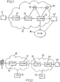
On se réfère ici à la
- une entité P-CSCFs (pour "Proxy-CSCF") 12, qui est le premier points de contacts pour les terminaux dans l'IMS ;
- une entité S-CSCFs (pour "Serving-CSCF") 14, pour contrôler les sessions d'un terminal pendant toute la période où ce dernier est enregistré dans l'IMS ;et
- une entité I-CSCFs (pour "Interrogating-CSCF") 13, qui représente un point d'entrée du réseau pour des sessions multimédia entre un utilisateur du réseau et un utilisateur appartenant à un autre réseau du même type.
- a P-CSCFs entity (for “Proxy-CSCF”) 12, which is the first point of contact for the terminals in the IMS;
- an entity S-CSCFs (for “Serving-CSCF”) 14, to control the sessions of a terminal during the entire period when the latter is registered in the IMS; and
- an entity I-CSCFs (for “Interrogating-CSCF”) 13, which represents a network entry point for multimedia sessions between a user of the network and a user belonging to another network of the same type.
Les entités I-CSCF 13 et S-CSCF 14 peuvent être reliées à un serveur HSS 15 (pour "Home Subscriber Server"), qui opère en tant que HLR (pour "Home Location Register") et contient en outre des fonctions relatives au domaine IP multimédia.The I-
Une telle architecture comprend en outre un serveur d'application, ou AS pour 'Application Server' 16.Such an architecture further comprises an application server, or AS for “Application Server” 16.
Un terminal 11 peut se connecter au réseau IMS 10.A terminal 11 can connect to the
Des centres d'appels d'urgence 23, ou PSAP pour 'Public Safety Answering Point', peuvent être reliés à une telle architecture via un réseau GSTN 18, pour 'General Switched Telephone Network' ou PSTN pour 'Public Switched Telephone Network' analogique ou numérique, ou encore directement via une session protocolaire adaptée de type SIP, pour 'Session Initiation Protocol' par exemple. Un centre d'appels d'urgence PSAP peut également être relié à une telle architecture via une liaison de type NGN, pour 'Next Generation Networks', c'est-à-dire une liaison selon le protocole IP permettant la transmission de données et de la voie.
La
A chacun de ces premier et second sous-systèmes sont respectivement associées des première et seconde fonctions de localisation adaptées pour déterminer une information de localisation d'un terminal qui est connecté dans leur sous-système respectif. Dans un mode de réalisation de la présente invention, ces première et seconde fonctions de localisation sont mises en œuvre respectivement dans des serveurs de localisation 21 et 25. Ces serveurs de localisation peuvent correspondre à des entités de réseau GMLC pour 'Gateway Mobility Location Center', tels que définis dans le document 3 GPP TS 23.271, ou encore correspondre à une entité de serveur de localisation tel que décrit dans la norme OMA/MLP v3.1 ou tout autre type d'entité capable de déterminer la localisation d'un utilisateur ou d'un équipement. Il convient toutefois de noter qu'une fonction de localisation d'un terminal peut être mis en oeuvre sur une quelconque entité de réseau du système.With each of these first and second subsystems are respectively associated first and second location functions suitable for determining location information of a terminal which is connected in their respective subsystem. In one embodiment of the present invention, these first and second location functions are implemented respectively in
Un serveur de localisation peut notamment réaliser des fonctions d'authentification, de vérification des souscriptions aux services requis, de localisation des utilisateurs, de conversion de format de l'information de localisation en fonction du service requérant cette information.A location server can in particular perform authentication functions, verification of subscriptions to the required services, location of users, format conversion of location information according to the service requesting this information.
Le second sous-système 20 est en outre adapté pour coopérer avec un centre d'appels d'urgence 23.The
La présente invention ne présente aucune limitation quant au type de liaison entre le centre d'appels d'urgence vers lequel un appel est routé et le réseau de télécommunications auquel ce centre d'appels est connecté. Ainsi, le centre d'appels d'urgence peut être directement relié via une entité P-CSCF au second sous-système 20, ou encore il peut être relié au second sous-système via une entité réseau de routage, telle qu'une passerelle par exemple. Les sections suivantes décrivent dans ces différents contextes, les échanges de messages entre les différentes entités du système requis pour une mise en œuvre de l'invention dans un mode de réalisation.The present invention does not present any limitation as to the type of link between the emergency call center to which a call is routed and the telecommunications network to which this call center is connected. Thus, the emergency call center can be directly linked via a P-CSCF entity to the
Selon un mode de réalisation de la présente invention, les étapes de routage d'appels urgents et de localisation de l'appelant peuvent avantageusement être réalisées de manière parallèle.According to an embodiment of the present invention, the steps of routing urgent calls and locating the caller can advantageously be carried out in parallel.
La
Un terminal 11 initie un appel d'urgence dans le réseau IMS 10, en émettant un message d'initiation d'appel 301 'INVITE' selon le protocole SIP à destination de l'entité P-CSCF 12 du premier sous-système.A terminal 11 initiates an emergency call in the
L'entité P-CSCF 12 transmet le message 'INVITE' 301 sous la forme d'un message 'INVITE' 302 à l'entité de réseau S-CSCF 14. Cette dernière est adaptée pour router le message selon une fonction de routage déterminée vers le centre d'appels 23.The P-
En général, dans le réseau IMS 10 auquel se connecte le terminal 11, lorsqu'un appel urgent est traité, un contexte de communication PDP spécifique aux appels d'urgence est créé de sorte notamment à gérer la priorité des messages échangés au cours de cet appel. Un tel contexte d'urgence est géré au niveau de l'entité S-CSCF 14.In general, in the
On peut également prévoir avantageusement qu'un élément S-CSCF dédié au traitement des appels d'urgence puisse être mis en œuvre et ainsi éviter des interférences entre appels qui ne nécessitent pas un traitement à caractère urgent et les autres appels.It is also advantageously possible to provide that an S-CSCF element dedicated to the processing of emergency calls can be implemented and thus to avoid interference between calls which do not require urgent processing and the other calls.
Dans des services de localisation autres que ceux liés aux services d'urgence, un accord de l'utilisateur est requis avant de fournir une information relative à sa localisation. En revanche, pour une localisation de l'utilisateur aux fins de traiter un appel d'urgence, généralement, aucun contrôle des droits de l'utilisateur n'est mis en œuvre de sorte à accélérer la prise en charge de l'appelant.In location services other than those related to emergency services, user consent is required before providing location information. On the other hand, for a location of the user for the purpose of handling an emergency call, generally, no control of the rights of the user is implemented so as to accelerate the support of the caller.
En général, en outre, lors d'un tel appel effectué par un terminal mobile ayant une carte de type carte SIM, pour 'Subscriber Identity Module', aucune vérification relative à cette carte n'est mise en œuvre contrairement au cas des appels classiques.In general, moreover, during such a call made by a mobile terminal having a SIM card type card, for 'Subscriber Identity Module', no verification relating to this card is implemented, unlike in the case of conventional calls.
Cet example couvre toutes les implémentations possibles de la fonction de routage mise en œuvre au niveau de l'entité S-CSCF 14 pour router l'appel d'urgence. Ainsi, cette fonction de routage peut être implémentée par exemple directement sur l'entité S-CSCF 14, ou encore sur une autre entité du réseau IMS 10. Elle peut par exemple être implémentée sur une entité de routage spécifique. Elle peut aussi être localisée sur un serveur de localisation, ou encore sur une entité de réseau P-CSCF.This example covers all possible implementations of the routing function implemented at S-
Cette fonction de routage peut être adaptée pour gérer le routage des appels d'urgence reçus dans le réseau IMS 10 exclusivement. Dans ce cas, cette fonction de routage est dédiée au réseau IMS 10, ou premier sous-système de télécommunications. Cette fonction peut aussi être adaptée pour gérer le routage des appels d'urgence reçus à la fois dans les réseaux IMS 10 et 20. De manière plus générale, cette fonction de routage peut être une fonction globale, commune aux deux sous-systèmes de télécommunications du système.This routing function can be adapted to manage the routing of emergency calls received in the
Une telle table de routage peut être gérée par le S-CSCF. Il est également possible de prévoir que cette table de routage soit gérée par n'importe quel équipement du réseau.Such a routing table can be managed by the S-CSCF. It is also possible to provide for this routing table to be managed by any device in the network.
On note que la présente invention peut être aisément appliquée à un système de télécommunications comprenant plus de deux sous-systèmes de télécommunications. Dans ce cas, avantageusement, la fonction de routage peut être commune à tous les sous-systèmes de télécommunications du système considéré, c'est-à-dire à un ensemble de réseaux de télécommunication sur lesquels les appels d'urgence peuvent être transmis.Note that the present invention can be easily applied to a telecommunications system comprising more than two telecommunications subsystems. In this case, advantageously, the routing function can be common to all the telecommunications subsystems of the system considered, that is to say to a set of telecommunications networks over which emergency calls can be transmitted.
Dans un example, le système de télécommunications comprend une pluralité de centres d'appels d'urgence. La fonction de routage peut alors avantageusement être adaptée pour gérer une liste de centre d'appels d'urgence et pour sélectionner un des centres d'appels d'urgence en fonction d'une information d'aide au routage reçue depuis le terminal appelant.In one example, the telecommunications system includes a plurality of emergency call centers. The routing function can then advantageously be adapted to manage a list of emergency call centers and to select one of the emergency call centers as a function of routing assistance information received from the calling terminal.
Ainsi, une telle fonction de routage peut notamment prendre en compte une indication de localisation approximative du terminal appelant qui est incluse dans le message d'initiation d'appel à router. Par conséquent, la fonction de routage peut sélectionner le centre d'appels d'urgence le plus proche du terminal ou, tout au moins, depuis lequel le terminal appelant est le plus accessible. Une indication de localisation approximative comprise dans le message d'initiation d'appel peut correspondre par exemple à un identifiant de la cellule dans laquelle est situé le terminal, ou cellld, ou plus généralement, une information relative au réseau d'accès, telle qu'un type d'accès comme par exemple un accès de type IEEE 802.11a, ou encore de type 3GPP UTRAN FDD, accompagnée d'une information sur l'accès comme par exemple un identifiant de la cellule dans un accès de type 3GPP UTRAN.Thus, such a routing function can in particular take into account an indication of the approximate location of the calling terminal which is included in the call initiation message to be routed. Therefore, the routing function can select the emergency call center closest to the terminal or, at least, from which the calling terminal is most accessible. An indication of approximate location included in the call initiation message may correspond, for example, to an identifier of the cell in which the terminal is located, or cellld, or more generally, information relating to the access network, such as a type of access such as for example an access of the IEEE 802.11a type, or even of the 3GPP UTRAN FDD type, accompanied by information on the access such as for example an identifier of the cell in an access of the 3GPP UTRAN type.
On peut alors prévoir de prendre en compte des critères qui permettent d'évaluer le temps de parcours entre le centre d'appels et l'appelant tels que par exemple des informations de trafic routier. On peut également prévoir de prendre en considération des informations relatives à la disponibilité d'une pluralité de centres d'appels proches de l'appelant.It is then possible to provide for taking into account criteria which make it possible to evaluate the travel time between the call center and the caller, such as, for example, road traffic information. It is also possible to provide for taking into consideration information relating to the availability of a plurality of call centers close to the caller.
La présente invention ne présente aucune limitation quant au mécanisme de sélection du centre d'appels au niveau de l'entité de gestion de la table de routage.The present invention does not present any limitation as to the mechanism for selecting the call center at the level of the management entity of the routing table.
En sélectionnant un centre d'appels d'urgence et en routant ainsi, le traitement de l'appel d'urgence peut être réalisé de manière efficace, puisque la fonction de routage est en mesure sur la base de cette indication reçue dans le message d'initiation d'appel de faire une sélection pertinente du centre d'appels vers lequel diriger l'appel d'urgence. En outre, un tel routage peut être réalisé rapidement, puisque la fonction de routage n'attend pas qu'une étape de localisation soit effectuée avant de router l'appel d'urgence. Ainsi, aucun délai significatif n'est introduit dans un tel routage d'appel. Or, la rapidité de traitement d'appel est une caractéristique très importante dans un système de télécommunications offrant un service d'urgence.By selecting an emergency call center and thus routing, the emergency call processing can be carried out efficiently, since the routing function is able on the basis of this indication received in the message. 'call initiation to make a relevant selection of the call center to which to direct the emergency call. Furthermore, such routing can be performed quickly, since the routing function does not wait for a location step to be performed before routing the emergency call. Thus, no significant delay is introduced in such call routing. However, the speed of call processing is a very important characteristic in a telecommunications system offering an emergency service.
Dans l'example illustré en
Ainsi, l'entité S-CSCF 14, sur réception du message d'initiation d'appel 302, requiert auprès de la fonction de routage 31 les informations utiles pour le routage de ce message 302. A cet effet, elle émet à destination de la fonction de routage un message 303 'Routing Request' et reçoit depuis cette fonction de routage un message 304 'Routing Response'. Sur réception de ce dernier message, l'entité S-CSCF 14 est en mesure de router le message d'initiation d'appel d'urgence vers l'entité S-CSCF 24 du second sous-système de télécommunications, c'est-à-dire le réseau IMS 20, sous la forme d'un message 305 'INVITE' selon le protocole SIP.Thus, the S-
L'entité S-CSCF 24 transmet ce message à l'entité P-CSCF 22 sous la forme d'un message 'INVITE' 306 selon le protocole SIP. Cette dernière entité 22 transmet enfin ce message d'initiation d'appel d'urgence à destination du centre d'appels 23, sous la forme d'un message 'INVITE' 307 selon le protocole SIP.The S-
Puis, l'appel d'urgence est établi 319 entre le centre d'appels 23 et le terminal 11, suite à l'émission par le centre d'appels d'urgence 23 d'un message '200 OK' selon le protocole SIP, sous la forme d'un message 308 à destination de l'entité P-CSCF 22, puis sous la forme d'un message 309 depuis cette dernière entité vers l'entité S-CSCF 24, puis sous la forme d'un message 310 vers l'entité S-CSCF 14, puis sous la forme d'un message 311 vers l'entité P-CSCF 12 et enfin sous la forme d'un message 312 depuis cette dernière entité vers le terminal 11.Then, the emergency call is established 319 between the
L'appel d'urgence est ainsi établi avantageusement sans attendre qu'une quelconque étape de localisation précise de l'appelant ait été réalisée. En outre, en procédant par un routage sur la base d'une indication de localisation approximative, lorsque l'appel peut être routé vers une pluralité de centre d'appels d'urgence, on est en mesure de sélectionner le centre d'appels le plus approprié au traitement de l'appel initié en fonction de l'accessibilité de l'appelant par rapport au centre qui va traiter cet appel d'urgence.The emergency call is thus advantageously established without waiting for any step of precise location of the caller to have been performed. Further, by routing on the basis of an approximate location indication, when the call can be routed to a plurality of emergency call centers, one is able to select the call center the most. more appropriate to the treatment of the call initiated according to the accessibility of the caller in relation to the center which will handle this emergency call.
Puis, de manière parallèle au routage de l'appel d'urgence au niveau de l'entité S-CSCF 14, une étape de localisation de l'appelant est déclenchée. En effet, sur réception du message d'initiation de l'appel d'urgence 302, l'entité S-CSCF 14 non seulement lance une procédure de routage de ce message vers un centre d'appels d'urgence, comme décrite ci-avant, mais elle lance également une procédure de localisation de l'appelant en émettant un message 313 'locRqst' selon par exemple un protocole du type MLP, pour 'Mobile Location Protocol' à destination du serveur de localisation 21 qui est associé au réseau IMS 10.Then, in parallel with the routing of the emergency call at the level of the S-
Dans un example, ce message de requête de localisation indique un identifiant du terminal appelant, ainsi qu'une adresse du serveur de localisation associé au réseau IMS 20 auquel est relié le centre d'appels d'urgence 23 vers lequel l'appel d'urgence est routé. Un tel identifiant peut être, par exemple, un numéro d'appel du terminal. Cet example couvre toute méthode permettant à l'entité S-CSCF 14 de récupérer l'adresse du serveur de localisation associé au réseau IMS 20. On peut par exemple prévoir qu'une telle adresse est disponible depuis la fonction de routage ou encore à partir de tout autre base de données permettant d'associer une adresse de serveur de localisation et le centre d'appels sélectionné.In one example, this location request message indicates an identifier of the calling terminal, as well as an address of the location server associated with the
De préférence, le serveur de localisation 21 répond à l'entité S-CSCF 14 par un message d'accusé de réception 314 'locResp'.Preferably, the
Dans un mode de réalisation de la présente invention, le serveur de localisation 21 détermine une information de localisation du terminal 11.In one embodiment of the present invention, the
Aucune limitation n'est attachée au mécanisme de localisation mis en œuvre par un tel serveur de localisation. L'homme du métier connaît de nombreux mécanismes permettant de déterminer une localisation précise d'un appelant.No limitation is attached to the location mechanism implemented by such a location server. Those skilled in the art are aware of numerous mechanisms making it possible to determine a precise location of a caller.
Puis, une fois qu'une information de localisation est obtenue, le serveur de localisation 21 transmet cette information au serveur de localisation 25 associé au réseau IMS 20 correspondant au centre d'appels vers lequel l'appel d'urgence est routé, c'est-à-dire le second sous-système de télécommunications. A cet effet, un message 315 'locResp' indiquant cette information de localisation est émis depuis le serveur de localisation 21 à destination du serveur de localisation 25. De préférence, un message accusant réception 316 'locResp' de ce dernier message est transmis en réponse au serveur de localisation 21.Then, once a location information is obtained, the
L'étape de localisation d'un appelant dans un système de télécommunications selon un example est donc de préférence réalisée par le serveur de localisation associé au réseau IMS auquel est connecté l'appelant, puis l'information de localisation est transmise au serveur de localisation associé au réseau IMS auquel est relié le centre d'appels ayant en charge de traiter l'appel d'urgence.The step of locating a caller in a telecommunications system according to an example is therefore preferably carried out by the location server associated with the IMS network to which the caller is connected, then the location information is transmitted to the location server. associated with the IMS network to which the call center responsible for handling the emergency call is connected.
La présente invention couvre tous les types d'architectures dans lesquelles le centre d'appels d'urgence et le terminal sont connectés à des sous systèmes différents. Ainsi, les mêmes mécanismes de traitement d'appels d'urgence que ceux énoncés ci-dessus s'appliquent dans une architecture comprenant un ou plusieurs autres sous-systèmes, ou autres réseaux IMS, entre le réseau IMS 10 et le réseau IMS 20.The present invention covers all types of architectures in which the emergency call center and the terminal are connected to different subsystems. Thus, the same emergency call processing mechanisms as those set out above apply in an architecture comprising one or more other subsystems, or other IMS networks, between the
Puis, une fois que l'appel d'urgence est établi entre le terminal 11 et le centre d'appels d'urgence 23, le centre d'appels peut décider de requérir une localisation précise de l'appelant, en fonction de certaines caractéristiques de l'appel, notamment en fonction du type d'aide à fournir à l'appelant. Dans un tel contexte, le centre d'appels d'urgence transmet alors un message 317 'locRsqt' à destination du serveur de localisation 25 associé au sous-système auquel est relié le centre d'appels d'urgence 23, afin de requérir l'information de localisation relative à l'appelant. En réponse à ce dernier message, le serveur 25 envoie au centre d'appels d'urgence 23 un message 318 'locResp' comprenant l'information de localisation, préalablement reçue par le serveur de localisation 25 depuis le serveur de localisation 21 associé au premier sous-système 10.Then, once the emergency call is established between the terminal 11 and the
A l'issue de toutes ces étapes, d'une part un appel d'urgence est établi entre le terminal 11 et le centre d'appels d'urgence 23, et d'autre part ce dernier bénéficie d'une information de localisation précise de l'appelant de sorte à fournir de l'aide efficacement.At the end of all these steps, on the one hand an emergency call is established between the terminal 11 and the
Dans le cas où le serveur de localisation 23 n'est pas en mesure de localiser le terminal 11, aucune information de localisation relative au terminal n'est émise à destination du serveur de localisation 25. Dans ce contexte, lorsque le centre d'appels requiert auprès du serveur de localisation 25 une information de localisation relative au terminal 11, ce serveur de localisation 25 détermine cette information de localisation avant de la transmettre en réponse au centre d'appels d'urgence 23. Mais, un délai supplémentaire est alors introduit, ce qui peut avoir des conséquences importantes dans le traitement de l'appel en fonction du caractère d'urgence de ce dernier.In the event that the
La
Tel est le cas lorsque le centre d'appels 23 est relié au second sous-système via un réseau PSTN.This is the case when the
Dans un example, une telle passerelle correspond à une entité MGCF, pour 'Media Gateway Control Function', telle que définie pour l'IMS.In an example, such a gateway corresponds to an MGCF entity, for 'Media Gateway Control Function', as defined for the IMS.
Dans ce contexte, une telle passerelle 42 est adaptée pour opérer une conversion de protocole entre le protocole utilisé dans le second sous-système de télécommunications et le centre d'appels d'urgence 23. En l'espèce, cette passerelle 42 est apte à convertir les messages reçus selon le protocole SIP en messages selon un protocole de type ISUP, pour 'ISDN User Part'.In this context, such a
L'échange de messages selon un mode de réalisation de l'invention est très similaire à celui décrit en référence à la
Le message d'initiation d'appel 306 'INVITE' selon le protocole SIP émis par l'entité S-CSCF 24 dans le second sous-système 20 est reçu par la passerelle 42. Cette dernière convertit ce message selon le protocole SIP en un message 307 'IAM' selon le protocole ISUP et le transmet vers le centre d'appels d'urgence.The call initiation message 306 'INVITE' according to the SIP protocol sent by the S-
Ce dernier répond au message 307 par un message 'CONNECT' 308 selon le protocole ISUP transmis à destination de la passerelle 42.The latter responds to
Cette dernière convertit alors ce dernier message 308 en un message 309 '200 OK' selon le protocole SIP, qui est envoyé à destination de l'entité S-CSCF 24. Puis, ce message est transmis à l'entité S-CSCF 14 sous la forme d'un message 310 '200 OK', puis un message 311 vers l'entité P-CSCF 12 et un message 312 vers le terminal 11.The latter then converts this
L'étape de localisation est similaire à celle décrite en référence à la
A l'issue de cet échange, l'appel 319 est établi entre le terminal 11 et le centre d'appels 23 qui est relié au second sous-système 20 par un réseau PSTN.At the end of this exchange, the
La présente invention trouve également des applications dans n'importe quel système comprenant un sous-système correspondant à un réseau mobile cellulaire. La
Dans cet example, le premier sous-système de télécommunications correspond à un réseau mobile cellulaire de type UMTS, pour 'Universal Mobile Telecommunications System', comprenant une entité réseau RAN, pour 'Radio Access Network', en charge de gérer l'accès des terminaux et une entité MSC, pour 'Mobile Switching Center', en charge de contrôler et commuter les appels. Une fonction de routage 31, similaire à celle décrite en référence à la
Le terminal 11 initie un appel d'urgence en émettant un message 301 'IAM' selon le protocole ISUP à destination de l'entité RAN 53. Ce message est transmis à l'entité MSC 54. Puis, cette dernière est adaptée pour router cet appel selon la fonction de routage 31. Les mêmes caractéristiques relatives à la fonction de routage que celles décrites ci-avant s'appliquent dans ce contexte d'appel également.The terminal 11 initiates an emergency call by sending a message 301 'IAM' according to the ISUP protocol to the
Puis, l'entité MSC 54 obtient depuis la fonction de routage 31 des informations lui permettant de router cet appel vers le centre d'appels d'urgence 23. Ainsi, le message 302 est transmis au MSC 55 du second sous-système de télécommunications 20, sous la forme d'un message 305 'IAM' selon le protocole ISUP.Then, the
Puis, l'entité MSC 55 transmet ce message sous la forme d'un message 306 'IAM au centre d'appels d'urgence 23. Ce dernier répond par l'émission d'un message 307 'CONNECT' selon le protocole ISUP, à destination du MSC 55. Ce dernier transmet ce message au MSC 54 sous la forme d'un message 308 'CONNECT'. Puis, le MSC 54 transmet ce message sous la forme d'un message 309 'CONNECT', qui transmet enfin ce dernier message sous la forme d'un message 310 'CONNECT' selon le protocole ISUP au terminal 11.Then, the
Parallèlement au traitement de routage de l'appel d'urgence tel que décrit ci-dessus, l'entité MSC 54 requiert, auprès d'une fonction de localisation 21 associée au premier sous-système de télécommunications, une procédure de localisation du terminal 11 en émettant un message 311 'locRqst' à destination du serveur de localisation 21. De préférence, ce dernier lui répond en accusant réception de cette requête par l'émission d'un message 312 'locRsp'.In parallel with the routing processing of the emergency call as described above, the
Le serveur de localisation met en œuvre une procédure de localisation du terminal 11, à l'issue de laquelle il obtient une information de localisation de l'appelant. Cette dernière est alors transmise depuis ce serveur de localisation 21 à destination du serveur de localisation 25 associé au second sous-système de télécommunications par l'émission d'un message 313 'location Report'. Puis, le serveur de localisation associé au second sous-système 20 accuse réception de cette information en émettant un message 314 'locRsp'.The location server implements a procedure for locating the terminal 11, at the end of which it obtains information on the location of the caller. The latter is then transmitted from this
Ensuite, comme décrit précédemment, le centre d'appels d'urgence 23 peut recevoir l'information de localisation depuis le serveur de localisation 25, soit automatiquement, soit sur requête.Then, as described above, the
Il convient de noter que le premier sous-système peut correspondre au réseau auquel le terminal est abonné ou encore à tout autre réseau visité par le terminal lors de son itinérance, ou 'roaming'.It should be noted that the first subsystem can correspond to the network to which the terminal is subscribed or even to any other network visited by the terminal during its roaming, or “roaming”.
La
Ainsi, dans un mode de réalisation de la présente invention, on peut prévoir que le serveur de localisation 21 transmet l'information de localisation au serveur de localisation global. Ce dernier est alors en mesure de fournir une telle information de localisation au centre d'appels en charge de l'appel d'urgence du terminal 11. Ainsi, une architecture hiérarchisée permet de centraliser les informations de localisation des appelants relatives au service d'urgence au niveau du serveur de localisation global.Thus, in one embodiment of the present invention, provision can be made for the
Lorsque, dans une telle architecture, plusieurs centres d'appels d'urgence sont susceptibles de prendre en charge l'appel d'urgence du terminal 11, on peut prévoir que tous les centres d'appels d'urgence du système de télécommunications considéré ont accès à ce serveur.When, in such an architecture, several emergency call centers are capable of handling the emergency call from
La fonction de localisation globale 61 peut fournir à différentes applications 62 des informations de localisations obtenues depuis les serveurs de localisation des différents sous-systèmes. En effet, d'autres services de télécommunications, autre qu'un service d'appels d'urgence peut se baser avantageusement sur des informations de localisation centralisées au niveau de la fonction de localisation globale.The
En se référant aux modes de réalisation décrits ci-avant en référence aux
La
Il peut en outre comprendre, lorsque le système de télécommunications comprend une pluralité de centre d'appels, une unité de sélection 73 adaptée pour sélectionner, en fonction d'une information d'aide au routage, un centre d'appels 23 pour router l'appel d'urgence. Par ailleurs, ce dispositif de routage peut être mutualisé pour un ensemble de sous-systèmes de télécommunications. Par exemple, le dispositif de routage pour les réseaux de type PSTN peut être réalisé par le dispositif qui prend en charge des réseaux de type UMTS.It can further comprise, when the telecommunications system comprises a plurality of call centers, a
La
La
Claims (6)
- Method for managing a call of a terminal (11) in a telecommunications system offering a call routing and location service; said telecommunications system comprising firstly a call centre (23) and secondly at least one first and one second telecommunications subsystem that are connected to one another (10, 20);
a first location function (21) being associated with the first telecommunications subsystem and a second location function (25), different from the first location function, being adapted to cooperate with the call centre;
said call centre being connected to the second telecommunications subsystem;
said method comprising the following steps:/a/ in the first subsystem:- routing a call initiation message (301), received from said terminal, to the call centre, via the second telecommunications subsystem; and- providing (313) the first location function with an identifier of the terminal included in the call initiation message;/b/ in the first location function, determining location information of the terminal, associated with the identifier of the terminal provided by the first subsystem, and then transmitting the location information to the second location function, wherein the second location function (25) is a global location function (61); and wherein the call centre requests the location information from this global location function,
wherein, when the telecommunications system comprises a plurality of call centres, a routing function (31) is adapted to select, on the basis of routing assistance information received from the terminal, a call centre (23) for routing the call initiation message, and
wherein the routing assistance information corresponds to information relating to the type of network access, which is indicated in the call initiation message, wherein the second location function (25) is associated with the second subsystem (20); and wherein the second location function is determined on the basis of the call centre. - Method for managing a call according to Claim 1, furthermore comprising the following step:
/c/ at the call centre,- receiving the location information of the terminal from the second location function (317, 318). - Method for managing a call according to Claim 1, wherein the routing function is common to the telecommunications subsystems (10, 20).
- Routing device (31) for routing a call in a telecommunications system offering a call routing and location service; said telecommunications system comprising firstly at least one call centre (23) and secondly at least one first and one second telecommunications subsystem that are connected to one another (10, 20); said call centre being connected to the second subsystem; said routing device comprising: a database (71) comprising an association between routing assistance information and the call centre; and an interface unit (72) adapted firstly to receive a call routing information request message (303), said request message comprising the routing assistance information, and secondly to transmit a routing information message (304) indicating the call centre to which the call should be routed, furthermore comprising, when the telecommunications system comprises a plurality of call centres, each one being adapted to cooperate with a location server, a selection unit (73) adapted to select, on the basis of routing assistance information received in the request message (303), firstly a call centre (23) for routing the call and secondly said location server with which said selected call centre is adapted to cooperate, and
wherein the routing assistance information corresponds to information relating to the type of network access, which is indicated in the call initiation message, wherein the second location function (25) is associated with the second subsystem (20); and wherein the second location function is determined on the basis of the call centre. - Telecommunications system offering a call routing and location service and comprising:- a call centre (23);- at least one first and one second telecommunications subsystem that are connected to one another (10, 20);- a first location server (21), said location server being associated with the first location subsystem (10) and comprising: a first interface unit (81) adapted to receive, from the first telecommunications subsystem (10), a location request message (313) for a terminal, said request message indicating an identifier of the terminal and a second location server (25); a determination unit (82) for determining location information of a terminal on the basis of an identifier of the terminal; adapted to determine location information of a terminal in the first telecommunications subsystem; and a second interface unit (83) adapted to transmit said location information to said second location server (25); and- the second location server (25), different from the first location server, adapted to cooperate with the call centre, and comprising a first interface unit (91) adapted to receive the location information of the terminal in the first telecommunications subsystem (10) from the first location server and a second interface unit (92) adapted to transmit said location information to the call centre, said second location server (25) being a global server, the call centre being configured so as to request the location information from the second location server (25),
the telecommunications system furthermore comprising a routing device according to Claim 4,
wherein the routing assistance information corresponds to information relating to the type of network access, which is indicated in the call initiation message, said system being configured so as to implement the method according to Claim 1. - Computer program intended to be installed in a system according to Claim 5, comprising instructions able to implement a method according to any one of Claims 1 to 3 when the program is executed by processing means of the system according to Claim 5.
Applications Claiming Priority (2)
| Application Number | Priority Date | Filing Date | Title |
|---|---|---|---|
| FR0600877 | 2006-01-31 | ||
| PCT/FR2007/000173 WO2007088270A1 (en) | 2006-01-31 | 2007-01-30 | Locating and routing a call |
Publications (3)
| Publication Number | Publication Date |
|---|---|
| EP1980130A1 EP1980130A1 (en) | 2008-10-15 |
| EP1980130B1 true EP1980130B1 (en) | 2021-06-23 |
| EP1980130B8 EP1980130B8 (en) | 2021-08-04 |
Family
ID=37116200
Family Applications (1)
| Application Number | Title | Priority Date | Filing Date |
|---|---|---|---|
| EP07730890.6A Active EP1980130B8 (en) | 2006-01-31 | 2007-01-30 | Locating and routing a call |
Country Status (2)
| Country | Link |
|---|---|
| EP (1) | EP1980130B8 (en) |
| WO (1) | WO2007088270A1 (en) |
Citations (1)
| Publication number | Priority date | Publication date | Assignee | Title |
|---|---|---|---|---|
| WO2004021733A1 (en) * | 2002-08-30 | 2004-03-11 | Qualcomm Incorporated | Beacon for locating and tracking wireless terminals |
Family Cites Families (3)
| Publication number | Priority date | Publication date | Assignee | Title |
|---|---|---|---|---|
| GB2371454B (en) * | 1997-04-22 | 2002-10-02 | Ericsson Inc | Systems and methods for providing information to emergency service centers |
| US6873290B2 (en) * | 1999-01-08 | 2005-03-29 | Trueposition, Inc. | Multiple pass location processor |
| US20060239205A1 (en) * | 2003-06-27 | 2006-10-26 | Daniel Warren | Method of call routing |
-
2007
- 2007-01-30 WO PCT/FR2007/000173 patent/WO2007088270A1/en active Application Filing
- 2007-01-30 EP EP07730890.6A patent/EP1980130B8/en active Active
Patent Citations (1)
| Publication number | Priority date | Publication date | Assignee | Title |
|---|---|---|---|---|
| WO2004021733A1 (en) * | 2002-08-30 | 2004-03-11 | Qualcomm Incorporated | Beacon for locating and tracking wireless terminals |
Non-Patent Citations (2)
| Title |
|---|
| GARCIA-MARTIN M ET AL: "Network Working Group Request for Comments: 3455 Category: Informational", HEISEI 15 NEN 1 GATSU 31 NICHI, [RETRIEVAL DATE HEISEI 21 NEN 5 GATSU 11 NICHI],, 1 January 2003 (2003-01-01), pages 2 - 34, XP008139971 * |
| OCG EMTEL: "Liaison Statement on EC Requirements on Emergency Telecommunications", 3GPP DRAFT; SP-030394, 3RD GENERATION PARTNERSHIP PROJECT (3GPP), MOBILE COMPETENCE CENTRE ; 650, ROUTE DES LUCIOLES ; F-06921 SOPHIA-ANTIPOLIS CEDEX ; FRANCE, vol. TSG SA, no. Frankfurt, GERMANY; 20030910, 10 September 2003 (2003-09-10), XP050200117 * |
Also Published As
| Publication number | Publication date |
|---|---|
| EP1980130A1 (en) | 2008-10-15 |
| EP1980130B8 (en) | 2021-08-04 |
| WO2007088270A1 (en) | 2007-08-09 |
Similar Documents
| Publication | Publication Date | Title |
|---|---|---|
| JP5274478B2 (en) | User plane location service via Session Initiation Protocol (SIP) | |
| EP1839421B1 (en) | A method and apparatus for handling emergency calls in a packet switched radio access network | |
| EP2107714B1 (en) | Method and apparatus for implementing a multimedia ring back tone service and multimedia caller identification service | |
| EP2227890B1 (en) | Methods for facilitating communication between Internet Protocol Multimedia Subsystem (IMS) devices and non-IMS devices | |
| KR101565626B1 (en) | A mobile switching center platform having interfaces with functionalities defined by an architecture that provides packet-switched multimedia subscriber services | |
| EP2291980B1 (en) | Remote network access via a visited network | |
| WO2006090081A1 (en) | Device for controlling a cs domain subscriber terminal access to an ims communication network services | |
| JP2009539317A (en) | Context-aware migration of communication sessions | |
| KR20070039454A (en) | Method and system for providing emergency location service using interoperability between ims core and access network | |
| CN103703737A (en) | Methods and apparatus for supporting the implementation of ims service continuity | |
| EP3257295B1 (en) | Method for configuring a terminal connected to a communication network | |
| US9491305B2 (en) | Call management adjustment in call continuity architecture | |
| EP2752039B1 (en) | Methods and apparatus for determining network support for other media during ims emergency sessions | |
| EP2926524A1 (en) | Routing of a service request aimed at an ims subscriber | |
| WO2016189218A1 (en) | Method and device for processing a signaling message related to a communication service of a client device | |
| EP1980130B1 (en) | Locating and routing a call | |
| WO2017203118A1 (en) | Fallback method in a telecommunications network | |
| EP3472993B1 (en) | Method for determining a set of encoding formats in order to establish a communication | |
| Costa-Requena et al. | Enhancing SIP with spatial location for emergency call services | |
| FR2980328A1 (en) | Method for treating request for e.g. emergency service, in Internet protocol multimedia subsystem network, involves querying cellular mapping function by real time collaboration server to obtain geographical identifier of mobile terminal | |
| EP4093145A1 (en) | Terminal implementing a communication method, and server implementing a method for establishing communication between two terminals | |
| FR2881593A1 (en) | Mobile terminal users` registering method for universal mobile telecommunication system, involves sending message having information relative to user authentication towards application server providing information to external application | |
| WO2015092238A1 (en) | Method and device for establishing enhanced communication | |
| FR2898239A1 (en) | METHOD FOR REDIRECTION OF A CALL AND MOBILE TERMINAL ADAPTED TO IMPLEMENT SUCH A METHOD | |
| WO2012056159A1 (en) | Methods and network in which a terminal can switch to standby mode |
Legal Events
| Date | Code | Title | Description |
|---|---|---|---|
| PUAI | Public reference made under article 153(3) epc to a published international application that has entered the european phase |
Free format text: ORIGINAL CODE: 0009012 |
|
| 17P | Request for examination filed |
Effective date: 20080718 |
|
| AK | Designated contracting states |
Kind code of ref document: A1 Designated state(s): AT BE BG CH CY CZ DE DK EE ES FI FR GB GR HU IE IS IT LI LT LU LV MC NL PL PT RO SE SI SK TR |
|
| 17Q | First examination report despatched |
Effective date: 20081031 |
|
| DAX | Request for extension of the european patent (deleted) | ||
| RAP1 | Party data changed (applicant data changed or rights of an application transferred) |
Owner name: ORANGE |
|
| STAA | Information on the status of an ep patent application or granted ep patent |
Free format text: STATUS: EXAMINATION IS IN PROGRESS |
|
| STAA | Information on the status of an ep patent application or granted ep patent |
Free format text: STATUS: EXAMINATION IS IN PROGRESS |
|
| RAP1 | Party data changed (applicant data changed or rights of an application transferred) |
Owner name: ORANGE |
|
| RIC1 | Information provided on ipc code assigned before grant |
Ipc: H04W 4/029 20180101ALI20210121BHEP Ipc: H04W 4/90 20180101ALN20210121BHEP Ipc: H04W 4/02 20180101ALN20210121BHEP Ipc: H04W 76/50 20180101ALN20210121BHEP Ipc: H04W 8/10 20090101AFI20210121BHEP |
|
| RIC1 | Information provided on ipc code assigned before grant |
Ipc: H04W 4/029 20180101ALI20210127BHEP Ipc: H04W 76/50 20180101ALN20210127BHEP Ipc: H04W 4/02 20180101ALN20210127BHEP Ipc: H04W 8/10 20090101AFI20210127BHEP Ipc: H04W 4/90 20180101ALN20210127BHEP |
|
| REG | Reference to a national code |
Ref country code: DE Ref legal event code: R079 Ref document number: 602007061188 Country of ref document: DE Free format text: PREVIOUS MAIN CLASS: H04Q0007380000 Ipc: H04W0008100000 |
|
| RIC1 | Information provided on ipc code assigned before grant |
Ipc: H04W 4/029 20180101ALI20210217BHEP Ipc: H04W 4/90 20180101ALN20210217BHEP Ipc: H04W 4/02 20180101ALN20210217BHEP Ipc: H04W 76/50 20180101ALN20210217BHEP Ipc: H04W 8/10 20090101AFI20210217BHEP |
|
| GRAP | Despatch of communication of intention to grant a patent |
Free format text: ORIGINAL CODE: EPIDOSNIGR1 |
|
| STAA | Information on the status of an ep patent application or granted ep patent |
Free format text: STATUS: GRANT OF PATENT IS INTENDED |
|
| RIC1 | Information provided on ipc code assigned before grant |
Ipc: H04W 8/10 20090101AFI20210310BHEP Ipc: H04W 4/029 20180101ALI20210310BHEP Ipc: H04W 76/50 20180101ALN20210310BHEP Ipc: H04W 4/90 20180101ALN20210310BHEP Ipc: H04W 4/02 20180101ALN20210310BHEP |
|
| INTG | Intention to grant announced |
Effective date: 20210331 |
|
| GRAS | Grant fee paid |
Free format text: ORIGINAL CODE: EPIDOSNIGR3 |
|
| GRAA | (expected) grant |
Free format text: ORIGINAL CODE: 0009210 |
|
| STAA | Information on the status of an ep patent application or granted ep patent |
Free format text: STATUS: THE PATENT HAS BEEN GRANTED |
|
| AK | Designated contracting states |
Kind code of ref document: B1 Designated state(s): AT BE BG CH CY CZ DE DK EE ES FI FR GB GR HU IE IS IT LI LT LU LV MC NL PL PT RO SE SI SK TR |
|
| REG | Reference to a national code |
Ref country code: GB Ref legal event code: FG4D Free format text: NOT ENGLISH |
|
| REG | Reference to a national code |
Ref country code: CH Ref legal event code: EP |
|
| REG | Reference to a national code |
Ref country code: DE Ref legal event code: R081 Ref document number: 602007061188 Country of ref document: DE Owner name: ORANGE, FR Free format text: FORMER OWNER: ORANGE, PARIS, FR |
|
| REG | Reference to a national code |
Ref country code: DE Ref legal event code: R096 Ref document number: 602007061188 Country of ref document: DE Ref country code: AT Ref legal event code: REF Ref document number: 1405358 Country of ref document: AT Kind code of ref document: T Effective date: 20210715 |
|
| REG | Reference to a national code |
Ref country code: IE Ref legal event code: FG4D Free format text: LANGUAGE OF EP DOCUMENT: FRENCH |
|
| RAP4 | Party data changed (patent owner data changed or rights of a patent transferred) |
Owner name: ORANGE |
|
| REG | Reference to a national code |
Ref country code: LT Ref legal event code: MG9D |
|
| PG25 | Lapsed in a contracting state [announced via postgrant information from national office to epo] |
Ref country code: BG Free format text: LAPSE BECAUSE OF FAILURE TO SUBMIT A TRANSLATION OF THE DESCRIPTION OR TO PAY THE FEE WITHIN THE PRESCRIBED TIME-LIMIT Effective date: 20210923 Ref country code: LT Free format text: LAPSE BECAUSE OF FAILURE TO SUBMIT A TRANSLATION OF THE DESCRIPTION OR TO PAY THE FEE WITHIN THE PRESCRIBED TIME-LIMIT Effective date: 20210623 Ref country code: FI Free format text: LAPSE BECAUSE OF FAILURE TO SUBMIT A TRANSLATION OF THE DESCRIPTION OR TO PAY THE FEE WITHIN THE PRESCRIBED TIME-LIMIT Effective date: 20210623 |
|
| REG | Reference to a national code |
Ref country code: AT Ref legal event code: MK05 Ref document number: 1405358 Country of ref document: AT Kind code of ref document: T Effective date: 20210623 |
|
| PG25 | Lapsed in a contracting state [announced via postgrant information from national office to epo] |
Ref country code: SE Free format text: LAPSE BECAUSE OF FAILURE TO SUBMIT A TRANSLATION OF THE DESCRIPTION OR TO PAY THE FEE WITHIN THE PRESCRIBED TIME-LIMIT Effective date: 20210623 Ref country code: GR Free format text: LAPSE BECAUSE OF FAILURE TO SUBMIT A TRANSLATION OF THE DESCRIPTION OR TO PAY THE FEE WITHIN THE PRESCRIBED TIME-LIMIT Effective date: 20210924 Ref country code: LV Free format text: LAPSE BECAUSE OF FAILURE TO SUBMIT A TRANSLATION OF THE DESCRIPTION OR TO PAY THE FEE WITHIN THE PRESCRIBED TIME-LIMIT Effective date: 20210623 |
|
| REG | Reference to a national code |
Ref country code: NL Ref legal event code: MP Effective date: 20210623 |
|
| PG25 | Lapsed in a contracting state [announced via postgrant information from national office to epo] |
Ref country code: EE Free format text: LAPSE BECAUSE OF FAILURE TO SUBMIT A TRANSLATION OF THE DESCRIPTION OR TO PAY THE FEE WITHIN THE PRESCRIBED TIME-LIMIT Effective date: 20210623 Ref country code: CZ Free format text: LAPSE BECAUSE OF FAILURE TO SUBMIT A TRANSLATION OF THE DESCRIPTION OR TO PAY THE FEE WITHIN THE PRESCRIBED TIME-LIMIT Effective date: 20210623 Ref country code: SK Free format text: LAPSE BECAUSE OF FAILURE TO SUBMIT A TRANSLATION OF THE DESCRIPTION OR TO PAY THE FEE WITHIN THE PRESCRIBED TIME-LIMIT Effective date: 20210623 Ref country code: NL Free format text: LAPSE BECAUSE OF FAILURE TO SUBMIT A TRANSLATION OF THE DESCRIPTION OR TO PAY THE FEE WITHIN THE PRESCRIBED TIME-LIMIT Effective date: 20210623 Ref country code: RO Free format text: LAPSE BECAUSE OF FAILURE TO SUBMIT A TRANSLATION OF THE DESCRIPTION OR TO PAY THE FEE WITHIN THE PRESCRIBED TIME-LIMIT Effective date: 20210623 Ref country code: PT Free format text: LAPSE BECAUSE OF FAILURE TO SUBMIT A TRANSLATION OF THE DESCRIPTION OR TO PAY THE FEE WITHIN THE PRESCRIBED TIME-LIMIT Effective date: 20211025 Ref country code: ES Free format text: LAPSE BECAUSE OF FAILURE TO SUBMIT A TRANSLATION OF THE DESCRIPTION OR TO PAY THE FEE WITHIN THE PRESCRIBED TIME-LIMIT Effective date: 20210623 Ref country code: AT Free format text: LAPSE BECAUSE OF FAILURE TO SUBMIT A TRANSLATION OF THE DESCRIPTION OR TO PAY THE FEE WITHIN THE PRESCRIBED TIME-LIMIT Effective date: 20210623 |
|
| PG25 | Lapsed in a contracting state [announced via postgrant information from national office to epo] |
Ref country code: PL Free format text: LAPSE BECAUSE OF FAILURE TO SUBMIT A TRANSLATION OF THE DESCRIPTION OR TO PAY THE FEE WITHIN THE PRESCRIBED TIME-LIMIT Effective date: 20210623 |
|
| REG | Reference to a national code |
Ref country code: DE Ref legal event code: R097 Ref document number: 602007061188 Country of ref document: DE |
|
| PG25 | Lapsed in a contracting state [announced via postgrant information from national office to epo] |
Ref country code: DK Free format text: LAPSE BECAUSE OF FAILURE TO SUBMIT A TRANSLATION OF THE DESCRIPTION OR TO PAY THE FEE WITHIN THE PRESCRIBED TIME-LIMIT Effective date: 20210623 |
|
| PLBE | No opposition filed within time limit |
Free format text: ORIGINAL CODE: 0009261 |
|
| STAA | Information on the status of an ep patent application or granted ep patent |
Free format text: STATUS: NO OPPOSITION FILED WITHIN TIME LIMIT |
|
| 26N | No opposition filed |
Effective date: 20220324 |
|
| PG25 | Lapsed in a contracting state [announced via postgrant information from national office to epo] |
Ref country code: IT Free format text: LAPSE BECAUSE OF FAILURE TO SUBMIT A TRANSLATION OF THE DESCRIPTION OR TO PAY THE FEE WITHIN THE PRESCRIBED TIME-LIMIT Effective date: 20210623 |
|
| PG25 | Lapsed in a contracting state [announced via postgrant information from national office to epo] |
Ref country code: MC Free format text: LAPSE BECAUSE OF FAILURE TO SUBMIT A TRANSLATION OF THE DESCRIPTION OR TO PAY THE FEE WITHIN THE PRESCRIBED TIME-LIMIT Effective date: 20210623 |
|
| REG | Reference to a national code |
Ref country code: CH Ref legal event code: PL |
|
| REG | Reference to a national code |
Ref country code: BE Ref legal event code: MM Effective date: 20220131 |
|
| PG25 | Lapsed in a contracting state [announced via postgrant information from national office to epo] |
Ref country code: LU Free format text: LAPSE BECAUSE OF NON-PAYMENT OF DUE FEES Effective date: 20220130 |
|
| PG25 | Lapsed in a contracting state [announced via postgrant information from national office to epo] |
Ref country code: BE Free format text: LAPSE BECAUSE OF NON-PAYMENT OF DUE FEES Effective date: 20220131 |
|
| PG25 | Lapsed in a contracting state [announced via postgrant information from national office to epo] |
Ref country code: LI Free format text: LAPSE BECAUSE OF NON-PAYMENT OF DUE FEES Effective date: 20220131 Ref country code: CH Free format text: LAPSE BECAUSE OF NON-PAYMENT OF DUE FEES Effective date: 20220131 |
|
| PG25 | Lapsed in a contracting state [announced via postgrant information from national office to epo] |
Ref country code: IE Free format text: LAPSE BECAUSE OF NON-PAYMENT OF DUE FEES Effective date: 20220130 |
|
| PGFP | Annual fee paid to national office [announced via postgrant information from national office to epo] |
Ref country code: DE Payment date: 20221220 Year of fee payment: 17 |
|
| PGFP | Annual fee paid to national office [announced via postgrant information from national office to epo] |
Ref country code: GB Payment date: 20231219 Year of fee payment: 18 |
|
| PGFP | Annual fee paid to national office [announced via postgrant information from national office to epo] |
Ref country code: FR Payment date: 20231219 Year of fee payment: 18 |
|
| PG25 | Lapsed in a contracting state [announced via postgrant information from national office to epo] |
Ref country code: HU Free format text: LAPSE BECAUSE OF FAILURE TO SUBMIT A TRANSLATION OF THE DESCRIPTION OR TO PAY THE FEE WITHIN THE PRESCRIBED TIME-LIMIT; INVALID AB INITIO Effective date: 20070130 |