EP1979126B1 - Filler material, in particular for improving the quality of a joint seam formed during thermal joining of two metallic structural components - Google Patents
Filler material, in particular for improving the quality of a joint seam formed during thermal joining of two metallic structural components Download PDFInfo
- Publication number
- EP1979126B1 EP1979126B1 EP07702908A EP07702908A EP1979126B1 EP 1979126 B1 EP1979126 B1 EP 1979126B1 EP 07702908 A EP07702908 A EP 07702908A EP 07702908 A EP07702908 A EP 07702908A EP 1979126 B1 EP1979126 B1 EP 1979126B1
- Authority
- EP
- European Patent Office
- Prior art keywords
- filler material
- structural components
- core
- coating
- filler
- Prior art date
- Legal status (The legal status is an assumption and is not a legal conclusion. Google has not performed a legal analysis and makes no representation as to the accuracy of the status listed.)
- Not-in-force
Links
Images

Classifications
-
- B—PERFORMING OPERATIONS; TRANSPORTING
- B23—MACHINE TOOLS; METAL-WORKING NOT OTHERWISE PROVIDED FOR
- B23K—SOLDERING OR UNSOLDERING; WELDING; CLADDING OR PLATING BY SOLDERING OR WELDING; CUTTING BY APPLYING HEAT LOCALLY, e.g. FLAME CUTTING; WORKING BY LASER BEAM
- B23K35/00—Rods, electrodes, materials, or media, for use in soldering, welding, or cutting
- B23K35/02—Rods, electrodes, materials, or media, for use in soldering, welding, or cutting characterised by mechanical features, e.g. shape
- B23K35/0255—Rods, electrodes, materials, or media, for use in soldering, welding, or cutting characterised by mechanical features, e.g. shape for use in welding
- B23K35/0261—Rods, electrodes or wires
- B23K35/0277—Rods, electrodes or wires of non-circular cross-section
Definitions
- the invention relates to a filler material, in particular for improving the quality of a joint seam formed during thermal joining of two metallic structural components.
- filler materials are frequently used in order to enhance the quality of the seam.
- filler materials that are specially matched to the aforesaid are used, which filler materials are, for example, added in the seam formation region during soldering or welding.
- the filler materials are present in strip- or wire shape.
- certain quantities of alloy elements have to be added to the filler material.
- due to the limited solubility of the alloy elements in a matrix material and due to the resulting separation problems up to now it has not been possible to implement alloy compositions at will.
- the invention provides a filler material for a joint seam formed during thermal joining of two metallic structural components according to the independent claims, further embodiments are incorporated in the dependent claims.
- WO 96/38259 describes a consumable welding electrode comprising a metal core and electrically insulating material in contact with the core, wherein one or more parts of the core are not covered by the insulating material on one side of the electrode to enable electrical contact to be made with the core between the ends of the electrode.
- the filler material according to an exemplary embodiment of the invention comprises a core and a coating that surrounds said core at least in sections
- the coating may comprise almost any concentrations of alloying additions for optimal seam formation during the thermal joining process, irrespective of any limitations in relation to the metallurgical composition of the core of the filler material.
- An embodiment of the filler material for understanding the invention provides for the filler material to comprise an essentially circular, oval or elliptic cross-sectional geometry. This makes it possible to easily store the filler material, for example in roll form.
- a further exemplary embodiment provides for the filler material to comprise an essentially H-shaped cross sectional geometry. Firstly, this allows optimum placement of the filler material in the seam formation region without the need for additional guidance. Secondly, this design makes it possible to affix or align the structural components to be connected by thermal joining. In this arrangement alignment takes place by the special geometric shape of the filler material itself. There is no need to provide separate supply of the filler material during the thermal joining process, so that considerable savings in both time and cost may be achieved.
- each case two limbs of the filler material are spaced apart by a distance that approximately corresponds to the material thickness of the structural components to be joined, so that the two structural components may be fixed by the filler material.
- the structural components in the seam formation region are slightly jammed or clamped between the limbs of the filler material so that reliable position fixing of the structural components in relation to each other prior to the thermal joining process is possible with the filler material itself.
- the material thickness of the middle web of the filler material approximately corresponds to the width of the joint seam to be formed. This ensures that there is no excessive material infeed in the region of the joint seam.
- a further exemplary embodiment provides for the coating to comprise a material thickness of less than 100 ⁇ m. In this way it is ensured that the coating may be produced easily while at the same time ensuring the supply of an adequate quantity of additional materials in the coating, which additional materials enhance the weld seam quality.
- a further exemplary embodiment provides for the core to comprise a metallic base material, in particular aluminium or an aluminium alloy.
- a metallic base material in particular aluminium or an aluminium alloy.
- the composition of the base material may essentially be selected irrespective of metallurgical requirements so as to provide optimum joint seam characteristics of the alloying material in the coating.
- the base material can, for example, be optimised in a targeted manner with a view to easy processability and/or low production costs.
- the base material essentially comprises aluminium or an aluminium alloy.
- a further exemplary embodiment provides for the coating to comprise a metallic alloying material, in particular copper, silicon, lithium or the like.
- a metallic alloying material in particular copper, silicon, lithium or the like.
- the composition or the quality of the metallic alloying material for coating may be focused in a targeted way on achieving optimum joint seam characteristics, largely independently of the requirements that the base metal has to meet.
- the metallic alloying material for coating preferably comprises copper, silicon, lithium, or a combination of these.
- Fig. 1 shows a cross section of a comparative filler material, in a first embodiment variant.
- the heterogeneous filler material 1 for improving the quality of joint seams in thermal joining processes, in particular in welding- or soldering processes comprises an essentially circular cross-sectional geometry.
- the filler material 1 is formed by a core 2 and a coating 3 that surrounds said core 2.
- the coating 3 concentrically encloses the core 2.
- the essentially circular cross-sectional geometry (cylindrical shape of the wire) of the filler material 1 makes it possible to easily store the filler material 1, for example in roll shape, and furthermore ensures easy feed-in or supply of the filler material to the seam formation region, which is of importance in particular in the case of automated thermal joining processes.
- Other cross-sectional shapes such as, for example, a polygonal, oval or elliptic cross-sectional geometry, are also imaginable.
- the core 2 of the filler material 1 may be formed using non-precious metals as base materials, for example aluminium, aluminium alloys or the like.
- Coating 3 of the core 2 may comprise an alloying material, for example copper, silicon, lithium or any desired combination of these materials.
- the core 2 and/or the coating 3 may comprise metals and/or metal alloys that are different from the above. The fact that the alloying composition of the coating 3 may be selected entirely without regard to any metallurgical restrictions concerning the chemical composition of the core 2 is of central importance.
- Fig. 2 shows a longitudinal section of the comparative filler material 1.
- the core 2 is completely, i.e. coaxially, enclosed by the coating 3.
- the core 2 may also be enclosed by the coating 3 only in parts.
- the coating 3 may be designed in longitudinal direction of the wire-shaped filler material 1 in the form of strips of alloying material, which strips are arranged on the core 2 so as to be evenly spaced apart from each other in radial direction.
- the coating 3 can, for example, be applied to the core 2 by known methods, such as, for example, by galvanic coating methods, brushing-on a paste-like metallic alloying material, spraying on a metallic alloying material, or by PVD coating processes.
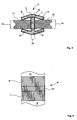
- Fig. 3 shows a cross section of the filler material according to an exemplary embodiment of the invention.
- a filler material 4 comprises a core 5 with an essentially H-shaped or double-T-shaped cross-sectional geometry.
- the core 5 of the filler material 4 may again comprise non-precious metals as a base material, for example aluminium, aluminium alloys or the like.
- the core 5 comprises a total of four limbs 6 to 9, which are connected to one another by a middle web 10 that extends essentially perpendicularly.
- the limbs 6, 7 as well as the limbs 8, 9 are pointing inward, in a slight V-shape, at an angle of less than 30° in relation to horizontal.
- the structural components 11, 12 can, for example, be sheet-like structures, for example aluminium sheeting or sheeting comprising an aluminium alloy. Furthermore, the structural components 11, 12 may be linear structures, for example reinforcement profiles comprising aluminium or an aluminium alloy.
- the core 5 of the filler material 4 again comprises a coating 15 all round, which coating 15 comprises a suitable alloying material, for example copper, silicon, lithium, or a combination of these metals so that a heterogeneous filler material 4 is created.
- the coating 15 may also be in place only in certain sections.
- the width 16 of the middle web 10 preferably essentially corresponds to the width of the joint seam to be formed or being created. In a manner different from that just mentioned, the width 16 of the middle web 10 may be narrower or wider.
- Fig. 4 shows a top view of the filler material 4 according to an exemplary embodiment of the invention.
- the structural components 11, 12 are fixed or aligned for a subsequent joining process and are kept together by the limbs 6, 7 connected by the middle web 10 and by the limbs 8, 9 (not shown in Fig. 4 ), arranged below the above.
Landscapes
- Engineering & Computer Science (AREA)
- Mechanical Engineering (AREA)
- Pressure Welding/Diffusion-Bonding (AREA)
- Nonmetallic Welding Materials (AREA)
- Gasket Seals (AREA)
- Joining Of Building Structures In Genera (AREA)
- Powder Metallurgy (AREA)
Description
- This application claims the benefit of German Patent Application No.
10 2006 003 191.1 filed January 24, 2006 , the disclosure of which is hereby incorporated herein by reference. - The invention relates to a filler material, in particular for improving the quality of a joint seam formed during thermal joining of two metallic structural components.
- During thermal joining of structural components, filler materials are frequently used in order to enhance the quality of the seam. Depending on various structural component materials, filler materials that are specially matched to the aforesaid are used, which filler materials are, for example, added in the seam formation region during soldering or welding. Usually the filler materials are present in strip- or wire shape. To obtain optimum seam quality, certain quantities of alloy elements have to be added to the filler material. However, due to the limited solubility of the alloy elements in a matrix material and due to the resulting separation problems, up to now it has not been possible to implement alloy compositions at will.
- Known filler materials are associated with a disadvantage in that the alloy elements are not soluble at unlimited concentrations in the filler material so that the concentration of alloy elements that is really required for optimum seam quality is not achievable. Furthermore, there is often the difficulty of homogeneously placing the alloy elements in the seam formation region.
- There may be a need to avoid the above disadvantages of the known filler materials for thermal joint connections.
- The invention provides a filler material for a joint seam formed during thermal joining of two metallic structural components according to the independent claims, further embodiments are incorporated in the dependent claims.
-
WO 96/38259 - Because the filler material according to an exemplary embodiment of the invention comprises a core and a coating that surrounds said core at least in sections, the coating may comprise almost any concentrations of alloying additions for optimal seam formation during the thermal joining process, irrespective of any limitations in relation to the metallurgical composition of the core of the filler material.
- An embodiment of the filler material for understanding the invention provides for the filler material to comprise an essentially circular, oval or elliptic cross-sectional geometry. This makes it possible to easily store the filler material, for example in roll form.
- A further exemplary embodiment provides for the filler material to comprise an essentially H-shaped cross sectional geometry. Firstly, this allows optimum placement of the filler material in the seam formation region without the need for additional guidance. Secondly, this design makes it possible to affix or align the structural components to be connected by thermal joining. In this arrangement alignment takes place by the special geometric shape of the filler material itself. There is no need to provide separate supply of the filler material during the thermal joining process, so that considerable savings in both time and cost may be achieved.
- According to a further exemplary embodiment of the filler material, in each case two limbs of the filler material are spaced apart by a distance that approximately corresponds to the material thickness of the structural components to be joined, so that the two structural components may be fixed by the filler material. In this way the structural components in the seam formation region are slightly jammed or clamped between the limbs of the filler material so that reliable position fixing of the structural components in relation to each other prior to the thermal joining process is possible with the filler material itself.
- According to a further exemplary embodiment of the filler material, the material thickness of the middle web of the filler material approximately corresponds to the width of the joint seam to be formed. This ensures that there is no excessive material infeed in the region of the joint seam.
- A further exemplary embodiment provides for the coating to comprise a material thickness of less than 100 µm. In this way it is ensured that the coating may be produced easily while at the same time ensuring the supply of an adequate quantity of additional materials in the coating, which additional materials enhance the weld seam quality.
- A further exemplary embodiment provides for the core to comprise a metallic base material, in particular aluminium or an aluminium alloy. In this way the composition of the base material may essentially be selected irrespective of metallurgical requirements so as to provide optimum joint seam characteristics of the alloying material in the coating. Thus, the base material can, for example, be optimised in a targeted manner with a view to easy processability and/or low production costs. Preferably the base material essentially comprises aluminium or an aluminium alloy.
- A further exemplary embodiment provides for the coating to comprise a metallic alloying material, in particular copper, silicon, lithium or the like. In this way the composition or the quality of the metallic alloying material for coating may be focused in a targeted way on achieving optimum joint seam characteristics, largely independently of the requirements that the base metal has to meet. In order to achieve optimum characteristics of the joint seam, the metallic alloying material for coating preferably comprises copper, silicon, lithium, or a combination of these.
- The following are shown in the drawing:
- Fig. 1
- a cross section of a comparative filler material,
- Fig. 2
- a longitudinal section of the comparative filler material,
- Fig. 3
- a cross section of an exemplary embodiment of the filler material according to the invention with two structural components that are to be thermally joined, and
- Fig. 4
- a top view of an exemplary embodiment of the filler material according to the invention with the two structural components.
- In the drawing, the same reference characters are used for identical construction elements.
-
Fig. 1 shows a cross section of a comparative filler material, in a first embodiment variant. - The
heterogeneous filler material 1 for improving the quality of joint seams in thermal joining processes, in particular in welding- or soldering processes, comprises an essentially circular cross-sectional geometry. Thefiller material 1 is formed by acore 2 and a coating 3 that surrounds saidcore 2. In the exemplary embodiment shown the coating 3 concentrically encloses thecore 2. The essentially circular cross-sectional geometry (cylindrical shape of the wire) of thefiller material 1 makes it possible to easily store thefiller material 1, for example in roll shape, and furthermore ensures easy feed-in or supply of the filler material to the seam formation region, which is of importance in particular in the case of automated thermal joining processes. Other cross-sectional shapes, such as, for example, a polygonal, oval or elliptic cross-sectional geometry, are also imaginable. - The
core 2 of thefiller material 1 may be formed using non-precious metals as base materials, for example aluminium, aluminium alloys or the like. Coating 3 of thecore 2 may comprise an alloying material, for example copper, silicon, lithium or any desired combination of these materials. Depending on the materials composition of the structural components that are to be thermally joined, in which materials composition thefiller material 1 is used as an auxiliary joining material to enhance the seam quality, thecore 2 and/or the coating 3 may comprise metals and/or metal alloys that are different from the above. The fact that the alloying composition of the coating 3 may be selected entirely without regard to any metallurgical restrictions concerning the chemical composition of thecore 2 is of central importance. -
Fig. 2 shows a longitudinal section of thecomparative filler material 1. Thecore 2 is completely, i.e. coaxially, enclosed by the coating 3. In a manner that differs from this, thecore 2 may also be enclosed by the coating 3 only in parts. For example, the coating 3 may be designed in longitudinal direction of the wire-shaped filler material 1 in the form of strips of alloying material, which strips are arranged on thecore 2 so as to be evenly spaced apart from each other in radial direction. - The coating 3 can, for example, be applied to the
core 2 by known methods, such as, for example, by galvanic coating methods, brushing-on a paste-like metallic alloying material, spraying on a metallic alloying material, or by PVD coating processes. -
Fig. 3 shows a cross section of the filler material according to an exemplary embodiment of the invention. - In this embodiment variant a
filler material 4 comprises a core 5 with an essentially H-shaped or double-T-shaped cross-sectional geometry. The core 5 of thefiller material 4 may again comprise non-precious metals as a base material, for example aluminium, aluminium alloys or the like. The core 5 comprises a total of fourlimbs 6 to 9, which are connected to one another by amiddle web 10 that extends essentially perpendicularly. Thelimbs limbs 8, 9 are pointing inward, in a slight V-shape, at an angle of less than 30° in relation to horizontal. As a result of the essentially H-shaped cross-sectional geometry of thefiller material 4 and of the slightly V-shaped alignment of thelimbs 6 to 9,structural components limbs structural components limbs material 13, 14 of thestructural components - The
structural components structural components - In the exemplary embodiment shown, the core 5 of the
filler material 4 again comprises acoating 15 all round, whichcoating 15 comprises a suitable alloying material, for example copper, silicon, lithium, or a combination of these metals so that aheterogeneous filler material 4 is created. Thecoating 15 may also be in place only in certain sections. - In the region of the
middle web 10, in the thermal joining process between the abutting edges of thestructural components 11, 12 a joint seam (not shown inFig. 3 ) arises, wherein thorough mixing of the materials of thestructural components coating 15 takes place. In this arrangement thewidth 16 of themiddle web 10 preferably essentially corresponds to the width of the joint seam to be formed or being created. In a manner different from that just mentioned, thewidth 16 of themiddle web 10 may be narrower or wider. - Due to the cross-sectional geometry, according to the invention, of the
filler material 4, which cross-sectional geometry is essentially H-shaped, feed-in of the base material and/or of the alloying material into the seam formation region occurs with precise local placement and precise metering. There is no need to separately feed in a conventional auxiliary welding or soldering material, so that this results in the potential of achieving considerable savings in both time and cost. -
Fig. 4 shows a top view of thefiller material 4 according to an exemplary embodiment of the invention. - The
structural components limbs middle web 10 and by thelimbs 8, 9 (not shown inFig. 4 ), arranged below the above. - It should be noted that the term "comprising" does not exclude other elements or steps and the "a" or "an" does not exclude a plurality. Also elements described in association with different embodiments may be combined.
- It should also be noted that reference signs in the claims shall not be construed as limiting the scope of the claims.
-
- 1
- Filler material
- 2
- Core
- 3
- Coating
- 4
- Filler material
- 5
- Core
- 6
- Limb
- 7
- Limb
- 8
- Limb
- 9
- Limb
- 10
- Middle web
- 11
- Structural component
- 12
- Structural component
- 13
- Material thickness
- 14
- Material thickness
- 15
- Coating
- 16
- Width
Claims (5)
- A filler material (1, 4) for a joint seam formed during thermal joining of two metallic structural components (11, 12), wherein the filler material (1, 4) comprises a core (2, 5) and a coating (3, 15) that surrounds said core at least in sections, and comprises an essentially H-shaped cross-sectional geometry, such that in each case two spaced limbs (6, 8; 7, 9) of the filler material (4) connected by a middle web (10) are spaced apart by a distance that approximately corresponds to the material thickness (13, 14) of structural components (11, 12) to be joined, so that the two structural components (11, 12) may be fixed by the filler material (4) and wherein the material thickness of the middle web (10) of the filler material (4) approximately corresponds to the width (16) of the joint seam to be formed.
- The filler material (1, 4) of any one of claims 1 wherein the coating (3, 15) comprises a material thickness of less than 100 µm.
- The filler material (1,4) of any one of claims 1 to 2, wherein the core (2, 5) comprises a metallic base material, in particular aluminium or an aluminium alloy.
- The filler material (1, 4) of any one of claims 1 to 3, wherein the coating (3, 15) comprises a metallic alloying material, in particular copper, silicon or lithium.
- The filler material (1, 4) of any one of claims 1 to 4, wherein the two respective spaced limbs (6, 8; 7, 9) of the filler material (4) are pointing inward, in a slight V-shape, at an angle of less than 30 ° in relation to the horizontal, such that they align and fix the two structural components (11, 12) to be joint.
Applications Claiming Priority (2)
| Application Number | Priority Date | Filing Date | Title |
|---|---|---|---|
| DE102006003191A DE102006003191B4 (en) | 2006-01-24 | 2006-01-24 | Additional material for the thermal joining of two metallic components and a corresponding use of a filler material |
| PCT/EP2007/000480 WO2007085389A1 (en) | 2006-01-24 | 2007-01-19 | Filler material, in particular for improving the quality of a joint seam formed during thermal joining of two metallic structural components |
Publications (2)
| Publication Number | Publication Date |
|---|---|
| EP1979126A1 EP1979126A1 (en) | 2008-10-15 |
| EP1979126B1 true EP1979126B1 (en) | 2012-11-14 |
Family
ID=37909843
Family Applications (1)
| Application Number | Title | Priority Date | Filing Date |
|---|---|---|---|
| EP07702908A Not-in-force EP1979126B1 (en) | 2006-01-24 | 2007-01-19 | Filler material, in particular for improving the quality of a joint seam formed during thermal joining of two metallic structural components |
Country Status (9)
| Country | Link |
|---|---|
| US (1) | US20100065612A1 (en) |
| EP (1) | EP1979126B1 (en) |
| JP (1) | JP2009523614A (en) |
| CN (1) | CN101370614B (en) |
| BR (1) | BRPI0706068A2 (en) |
| CA (1) | CA2629663A1 (en) |
| DE (1) | DE102006003191B4 (en) |
| RU (1) | RU2425743C2 (en) |
| WO (1) | WO2007085389A1 (en) |
Families Citing this family (2)
| Publication number | Priority date | Publication date | Assignee | Title |
|---|---|---|---|---|
| DE102008025647A1 (en) * | 2008-05-28 | 2009-12-17 | Lfk-Lenkflugkörpersysteme Gmbh | Stapling seam-free welding in the seam outer areas of components |
| US12025176B2 (en) | 2021-03-17 | 2024-07-02 | Steelcase Inc. | Clip fastener for privacy screen |
Family Cites Families (42)
| Publication number | Priority date | Publication date | Assignee | Title |
|---|---|---|---|---|
| DE610819C (en) * | 1934-03-20 | 1935-03-16 | Maurice Naeder | Process for welding butt joints |
| CH240000A (en) * | 1944-02-04 | 1945-11-30 | Steeden & Co Van | Welding electrode and process for its manufacture. |
| US2934180A (en) * | 1955-01-18 | 1960-04-26 | Andrew B Hammitt | Structural element |
| DE1016624B (en) * | 1956-02-04 | 1957-09-26 | Duerrwaechter E Dr Doduco | Sheathed wire solder for ceramic soldering and process for its production |
| GB902463A (en) * | 1959-01-06 | 1962-08-01 | Multicore Solders Ltd | Improvements in or relating to soft solder rods or wires |
| US3033145A (en) * | 1959-02-24 | 1962-05-08 | Grinnell Corp | Insert welding rings |
| US3017483A (en) * | 1959-06-22 | 1962-01-16 | Detroit Edison Co | Method of induction welding of stranded aluminum cable |
| US3738083A (en) * | 1969-11-25 | 1973-06-12 | Shimano & Co Ltd | Prefabricated house |
| US3676309A (en) * | 1970-02-04 | 1972-07-11 | Olin Mathieson | Aluminum welding wire electrode with an alumina coating containing phosphate |
| DE7123387U (en) * | 1971-06-18 | 1972-10-05 | Rosenthal Stemag Techn Keramik Gmbh | Jacketed solder in wire or tape form |
| US3778532A (en) * | 1972-07-03 | 1973-12-11 | Illinois Tool Works | Electrical circuit component having solder preform connection means |
| US4611830A (en) * | 1981-03-09 | 1986-09-16 | Von Ahrens Roger W | Partially consumable spacer chill rings and their use in welding pipe joints |
| FR2510927A1 (en) * | 1981-08-04 | 1983-02-11 | Gay Pierre | Rod for arc welding thin sheet - with elongated cross-section for edge to edge joints |
| FR2553321B1 (en) * | 1983-10-12 | 1986-09-12 | Snecma | WELDING WASHER AND WELDING METHOD USING THE SAME |
| ATE53790T1 (en) * | 1984-01-18 | 1990-06-15 | Norsk Hydro As | ALUMINUM MOLDED STRUCTURES COATED WITH RESIN BRAZE MATERIAL AND COATING METHOD. |
| GB8411823D0 (en) * | 1984-05-09 | 1984-06-13 | British Nuclear Fuels Plc | Butt welding pipe ends |
| US4703603A (en) * | 1985-06-17 | 1987-11-03 | Altech Industries, Inc. | Plywood sheeting spacer clip |
| US4913927A (en) * | 1986-02-06 | 1990-04-03 | Alcotec Wire Co. | Lubricated aluminum weld wire and process for spooling it |
| SU1586874A1 (en) * | 1988-01-27 | 1990-08-23 | Проектно-технологический институт "Энергомонтажпроект" | Method of fusion welding of butt joints of tubes |
| US5161909A (en) * | 1989-06-06 | 1992-11-10 | R. D. Werner Co., Inc. | Packaging clip |
| JPH03114692A (en) * | 1989-09-28 | 1991-05-15 | Showa Alum Corp | Aluminum alloy brazing filler metal |
| AT394637B (en) * | 1990-10-18 | 1992-05-25 | Electrovac | LOTPILLE |
| US5476725A (en) * | 1991-03-18 | 1995-12-19 | Aluminum Company Of America | Clad metallurgical products and methods of manufacture |
| JPH05285690A (en) * | 1992-04-15 | 1993-11-02 | Sumitomo Electric Ind Ltd | Composite material for welding and its production |
| US5525779A (en) * | 1993-06-03 | 1996-06-11 | Martin Marietta Energy Systems, Inc. | Intermetallic alloy welding wires and method for fabricating the same |
| US5820014A (en) * | 1993-11-16 | 1998-10-13 | Form Factor, Inc. | Solder preforms |
| US5422191A (en) * | 1994-02-14 | 1995-06-06 | Kaiser Aluminum & Chemical Corporation | Aluminum-lithium filler alloy for brazing |
| DE9404642U1 (en) * | 1994-03-18 | 1994-05-19 | Friedrich Knapp GmbH, 85591 Vaterstetten | Fastener |
| GB9511108D0 (en) * | 1995-06-01 | 1995-07-26 | Welding Inst | Consumable welding electrode and method |
| DE19639667C1 (en) * | 1996-09-27 | 1998-03-12 | Daimler Benz Aerospace Airbus | Process for welding profiles on large-format aluminum structural components using laser beams |
| US6426483B1 (en) * | 1998-02-17 | 2002-07-30 | Lincoln Global, Inc. | Electrode and method of making same |
| US6161751A (en) * | 1999-02-18 | 2000-12-19 | Precision Tube Technology, Inc. | Method of joining metal strip ends together using a consumable insert |
| DE60118313T2 (en) * | 2000-10-10 | 2006-08-31 | Illinois Tool Works Inc., Cook County | Aluminum welding core wire |
| US6869007B2 (en) * | 2001-01-26 | 2005-03-22 | Lucent Technologies Inc. | Oxidation-resistant reactive solders and brazes |
| US7776454B2 (en) * | 2001-12-14 | 2010-08-17 | EMS Solutions, Inc. | Ti brazing strips or foils |
| US20030116234A1 (en) * | 2001-12-21 | 2003-06-26 | Santella Michael L. | Consumable welding filler metal for cladding alloys |
| US7285747B2 (en) * | 2003-09-15 | 2007-10-23 | Atreva Np Inc. | Flux assisted gas tungsten arc welding utilizing consumable inserts for ultra low profile welding applications |
| AT500494B1 (en) * | 2004-05-27 | 2006-12-15 | Boehler Schweisstechnik | ADDITIVE MATERIAL FOR JOINT COMPOUNDS AND METHOD FOR THE PRODUCTION THEREOF |
| WO2006086185A2 (en) * | 2005-02-10 | 2006-08-17 | M & O Products, Inc. | H clip |
| US8274014B2 (en) * | 2006-05-25 | 2012-09-25 | Bellman-Melcor Development, Llc | Filler metal with flux for brazing and soldering and method of making and using same |
| US20090200363A1 (en) * | 2008-02-13 | 2009-08-13 | Trane International Inc. | Braze Ring |
| USD596482S1 (en) * | 2008-09-08 | 2009-07-21 | Marinucci Robert R | Wallboard edge clip |
-
2006
- 2006-01-24 DE DE102006003191A patent/DE102006003191B4/en not_active Expired - Fee Related
-
2007
- 2007-01-19 RU RU2008134328/02A patent/RU2425743C2/en not_active IP Right Cessation
- 2007-01-19 CN CN2007800029027A patent/CN101370614B/en not_active Expired - Fee Related
- 2007-01-19 CA CA002629663A patent/CA2629663A1/en not_active Abandoned
- 2007-01-19 WO PCT/EP2007/000480 patent/WO2007085389A1/en not_active Ceased
- 2007-01-19 US US12/223,147 patent/US20100065612A1/en not_active Abandoned
- 2007-01-19 BR BRPI0706068-8A patent/BRPI0706068A2/en active Search and Examination
- 2007-01-19 JP JP2008550695A patent/JP2009523614A/en active Pending
- 2007-01-19 EP EP07702908A patent/EP1979126B1/en not_active Not-in-force
Also Published As
| Publication number | Publication date |
|---|---|
| DE102006003191A1 (en) | 2007-11-15 |
| DE102006003191B4 (en) | 2011-03-17 |
| CN101370614A (en) | 2009-02-18 |
| RU2008134328A (en) | 2010-02-27 |
| RU2425743C2 (en) | 2011-08-10 |
| US20100065612A1 (en) | 2010-03-18 |
| CN101370614B (en) | 2012-12-19 |
| CA2629663A1 (en) | 2007-08-02 |
| BRPI0706068A2 (en) | 2011-03-22 |
| JP2009523614A (en) | 2009-06-25 |
| EP1979126A1 (en) | 2008-10-15 |
| WO2007085389A1 (en) | 2007-08-02 |
Similar Documents
| Publication | Publication Date | Title |
|---|---|---|
| US10052710B2 (en) | Resistance spot welding steel and aluminum workpieces using electrode weld face cover | |
| US20080182119A1 (en) | Projection weld and method for creating the same | |
| US20160346865A1 (en) | Resistance spot welding workpiece stack-ups of different combinations of steel workpieces and aluminum workpieces | |
| CN107160022A (en) | For aluminium workpiece and steel workpiece resistance spot welding match somebody with somebody composite electrode | |
| CA2570707A1 (en) | Bi-metallic connectors, method for producing the same, and method for connecting the same to a structure | |
| US20180222150A1 (en) | Method for joining dissimilar metals and articles comprising the same | |
| KR100997607B1 (en) | Bonding method | |
| CN109746560A (en) | The design of electrode welding face | |
| JP6539325B2 (en) | Heterojunction structure | |
| CN102632324A (en) | Method for welding dissimilar metals | |
| AU2005240655B2 (en) | Weld filler for welding dissimilar alloy steels and method of using same | |
| CN111037076A (en) | Quality welding of similar and dissimilar metal weld bodies with spaces between workpieces | |
| JP2005515074A5 (en) | ||
| US20100065612A1 (en) | Filler Material, In Particular For Improving The Quality Of A Joint Seam Formed During Thermal Joining Of Two Metallic Structural Components | |
| FI65177C (en) | SAETT ATT FOGA ALUMINUM TILL TITAN GENOM SVETSNING OCH EN SVETSPRODUKT AOSTADKOMMEN HAERIGENOM | |
| FI110270B (en) | Process for making an electrode and an electrode | |
| US20140264949A1 (en) | Gold die bond sheet preform | |
| JP6947591B2 (en) | Electrodes for spot welding | |
| US20100233507A1 (en) | Device with at least two interconnected metal parts | |
| JP2006060126A (en) | Method for manufacturing resistor | |
| Goecke | Low temperature brazing of zinc coated steel and steel/aluminium joints by setting ZnAl-alloys as brazing material | |
| JP2000135570A (en) | Welding method | |
| Sorokin | Filler materials for heat resistant nickel alloys welding(survey). Part 2. | |
| JP2001096374A (en) | Joining method of steel sheet and dissimilar metal sheet | |
| KR101916254B1 (en) | Metal plate having the welding additives and welding method using same |
Legal Events
| Date | Code | Title | Description |
|---|---|---|---|
| PUAI | Public reference made under article 153(3) epc to a published international application that has entered the european phase |
Free format text: ORIGINAL CODE: 0009012 |
|
| 17P | Request for examination filed |
Effective date: 20080509 |
|
| AK | Designated contracting states |
Kind code of ref document: A1 Designated state(s): DE FR GB IT SE |
|
| RIN1 | Information on inventor provided before grant (corrected) |
Inventor name: KOCIK, RAINER Inventor name: KASCHEL, SEBASTIAN Inventor name: HACKIUS, JENS Inventor name: SCHUMACHER, JENS |
|
| 17Q | First examination report despatched |
Effective date: 20081217 |
|
| DAX | Request for extension of the european patent (deleted) | ||
| RBV | Designated contracting states (corrected) |
Designated state(s): DE FR GB IT SE |
|
| GRAP | Despatch of communication of intention to grant a patent |
Free format text: ORIGINAL CODE: EPIDOSNIGR1 |
|
| GRAS | Grant fee paid |
Free format text: ORIGINAL CODE: EPIDOSNIGR3 |
|
| RBV | Designated contracting states (corrected) |
Designated state(s): FR GB IT SE |
|
| REG | Reference to a national code |
Ref country code: DE Ref legal event code: R108 |
|
| GRAA | (expected) grant |
Free format text: ORIGINAL CODE: 0009210 |
|
| RAP1 | Party data changed (applicant data changed or rights of an application transferred) |
Owner name: AIRBUS OPERATIONS GMBH |
|
| AK | Designated contracting states |
Kind code of ref document: B1 Designated state(s): FR GB IT SE |
|
| REG | Reference to a national code |
Ref country code: GB Ref legal event code: FG4D |
|
| REG | Reference to a national code |
Ref country code: DE Ref legal event code: R108 Effective date: 20121010 |
|
| PG25 | Lapsed in a contracting state [announced via postgrant information from national office to epo] |
Ref country code: SE Free format text: LAPSE BECAUSE OF FAILURE TO SUBMIT A TRANSLATION OF THE DESCRIPTION OR TO PAY THE FEE WITHIN THE PRESCRIBED TIME-LIMIT Effective date: 20121114 |
|
| PG25 | Lapsed in a contracting state [announced via postgrant information from national office to epo] |
Ref country code: IT Free format text: LAPSE BECAUSE OF FAILURE TO SUBMIT A TRANSLATION OF THE DESCRIPTION OR TO PAY THE FEE WITHIN THE PRESCRIBED TIME-LIMIT Effective date: 20121114 |
|
| PLBE | No opposition filed within time limit |
Free format text: ORIGINAL CODE: 0009261 |
|
| STAA | Information on the status of an ep patent application or granted ep patent |
Free format text: STATUS: NO OPPOSITION FILED WITHIN TIME LIMIT |
|
| 26N | No opposition filed |
Effective date: 20130815 |
|
| REG | Reference to a national code |
Ref country code: FR Ref legal event code: PLFP Year of fee payment: 10 |
|
| REG | Reference to a national code |
Ref country code: FR Ref legal event code: PLFP Year of fee payment: 11 |
|
| PGFP | Annual fee paid to national office [announced via postgrant information from national office to epo] |
Ref country code: FR Payment date: 20170120 Year of fee payment: 11 |
|
| PGFP | Annual fee paid to national office [announced via postgrant information from national office to epo] |
Ref country code: GB Payment date: 20170119 Year of fee payment: 11 |
|
| GBPC | Gb: european patent ceased through non-payment of renewal fee |
Effective date: 20180119 |
|
| PG25 | Lapsed in a contracting state [announced via postgrant information from national office to epo] |
Ref country code: FR Free format text: LAPSE BECAUSE OF NON-PAYMENT OF DUE FEES Effective date: 20180131 |
|
| REG | Reference to a national code |
Ref country code: FR Ref legal event code: ST Effective date: 20180928 |
|
| PG25 | Lapsed in a contracting state [announced via postgrant information from national office to epo] |
Ref country code: GB Free format text: LAPSE BECAUSE OF NON-PAYMENT OF DUE FEES Effective date: 20180119 |