EP1979047B1 - Mehrkammertakt für frühe schrittmachersteuerung - Google Patents
Mehrkammertakt für frühe schrittmachersteuerung Download PDFInfo
- Publication number
- EP1979047B1 EP1979047B1 EP06840254A EP06840254A EP1979047B1 EP 1979047 B1 EP1979047 B1 EP 1979047B1 EP 06840254 A EP06840254 A EP 06840254A EP 06840254 A EP06840254 A EP 06840254A EP 1979047 B1 EP1979047 B1 EP 1979047B1
- Authority
- EP
- European Patent Office
- Prior art keywords
- atrial
- pulse
- premature
- ventricular
- depolarization
- Prior art date
- Legal status (The legal status is an assumption and is not a legal conclusion. Google has not performed a legal analysis and makes no representation as to the accuracy of the status listed.)
- Not-in-force
Links
Images


Classifications
-
- A—HUMAN NECESSITIES
- A61—MEDICAL OR VETERINARY SCIENCE; HYGIENE
- A61N—ELECTROTHERAPY; MAGNETOTHERAPY; RADIATION THERAPY; ULTRASOUND THERAPY
- A61N1/00—Electrotherapy; Circuits therefor
- A61N1/18—Applying electric currents by contact electrodes
- A61N1/32—Applying electric currents by contact electrodes alternating or intermittent currents
- A61N1/36—Applying electric currents by contact electrodes alternating or intermittent currents for stimulation
- A61N1/362—Heart stimulators
- A61N1/3627—Heart stimulators for treating a mechanical deficiency of the heart, e.g. congestive heart failure or cardiomyopathy
Definitions
- the present invention relates generally to the field of cardiac pacing systems, and more particularly to a cardiac pacing device having pacing control for providing multi-chamber post extrasystolic potentiation (PESP) therapy.
- PESP multi-chamber post extrasystolic potentiation
- Modern cardiac pacing devices and systems are capable of providing PESP therapy to one or more chambers of the heart.
- a device providing PESP therapy prematurely excites the atria and/or the ventricles, causing a premature contraction. If timed properly, the premature contraction provides an effect that increases contractility, i.e., the ability of the myocardium to contract and relax.
- An increase in contractility leads to an increase in stroke volume (i.e., the amount of blood ejected from the ventricles per heartbeat).
- HF heart failure
- WO 2006/115890 and WO 03/020364 disclose a method and system for multi-site PESP.
- the present invention provides a device according to claim 1. Preferred embodiments are defined in the dependent claims.
- the present invention is used to provide multi-chamber timing for premature cardiac paces delivered as part of a PESP therapy.
- Premature cardiac paces delivered to a particular chamber are delivered based on sensed events within that chamber. For instance, a premature pulse delivered to the right atrium is based on a sensed atrial event within the right atrium.
- Providing premature atrial and ventricular premature pulses based on sensed or pulsed events detected in the respective chambers results in potentiation of each chamber being maximized.
- providing premature atrial paces based on atrial sensed or paced events provides better control of the mechanical rate of the heart.
- FIG. 1 is a diagram of implantable medical device (IMD) 10 capable of providing pacing therapy to heart H in accordance with the present invention.
- IMD 10 is presented herein as one embodiment of an intracardiac pacing system that embodies the pacing control of the present invention.
- the pacing control of the present invention may be adapted for use with any multiple chamber pacing or defibrillation system that allows for delivery of PESP therapy.
- IMD 10 includes hermetically-sealed housing 12, header 14, right atrial (RA) lead 16, and right ventricular (RV) lead 18.
- IMD 10 further includes circuitry and a power source, which are located within housing 12, for controlling the operation of IMD 10.
- the circuitry which includes the pacing control of the present invention, communicates with leads 16 and 18 through electrical connectors within header 14. Leads 16 and 18 extend from header 14 to right atrium RA and right ventricle RV, respectively, of heart H.
- Leads 16 and 18 carry one or more sensors/electrodes for sensing electrical signals attendant to the depolarization and repolarizataon of heart H, and further for providing pacing pulses for causing depolarization of cardiac tissue in the vicinity of the distal ends thereof.
- atrial ring and tip electrodes 20 and 22 are disposed at the distal end ofRA lead 16 and are located in right atrium RA.
- ventricular ring and tip electrodes 24 and 26 are disposed at the distal end of RV lead 18 and are located in right ventricle RV.
- FIG. 2 is a functional block diagram of the circuitry located within IMD 10. This block diagram is intended to be merely an example and corresponds only to a general functional organization of most presently available IMDs.
- the circuitry generally includes microcomputer circuit 50, input/output circuit 52, and data communications bus 54.
- Microcomputer circuit 50 includes microprocessor 56, system clock 58, on-board RAM memory 60, on-board ROM memory 62, off-board RAM/ROM memory 64, and digital controller/timer circuit 66 connected to microprocessor 56 and off-board RAM/ROM memory 64 via data communications bus 54.
- Microcomputer circuit 50 communicates with input/output circuit 52 to monitor electrical activity in heart H as well as to deliver appropriately-timed pulses to the various electrodes.
- Digital controller/timer circuit 66 includes digital timers and counters used to determine time between successive depolarizations in the atria and ventricles, as well as to provide various refractory, blanking, and other timing windows used to determ.ine delivery of paced pulses to the atria and ventricles.
- Digital controller/timer circuit 66 receives sensed activity signals and causes pacing pulses to be delivered via connections to leads 16 and 18.
- RA lead 16 is connected to digital controller/timer circuit 66 via output pulse generator 68, electrogram (EGM) amplifier 70, and sensing circuitry 72, which includes sense amplifier 74 and peak sense and threshold measurement circuitry 76.
- Sense amplifier 74 amplifies electrical cardiac signals sensed by RA lead 16 and provides an amplified signal to peak sense and threshold measurement circuitry 76, which in turn provides an indication of sensed cardiac events and measured sense amplifier threshold voltages to digital controller/timer circuit 66.
- Electrical signals sensed by RA lead 16 provide microcomputer 50 with information regarding depolarizations in right atrium RA. Signals received by RA lead 16 are also provided to EGM amplifier 70 and are converted into digital values by analog-to-digital converter (ADC) and multiplexer 77.
- ADC analog-to-digital converter
- ADC and multiplexer 77 provides a digitized version of the EGM signal, which IMD 10 may transmit when interrogated by an external programmer (not shown) to transmit a representation of a cardiac EGM.
- output pulse generator 68 Under the control of microcomputer circuit 50 and digital controller/timer circuit 66, output pulse generator 68 provides pacing pulses to RA lead 16.
- RV lead 18 is also connected to digital controller/timer circuit 66 via output pulse generator 78, EGM amplifier 80, and sensing circuitry 82, which includes sense amplifier 84 and peak sense and threshold measurement circuitry 86.
- Sense amplifier 84 amplifies electrical cardiac signals sensed by RV lead 18 and provides an amplified signal to peak sense and threshold measurement circuitry 86, which in turn provides an indication of sensed cardiac events and measured sense amplifier threshold voltages to digital controller/timer circuit 66.
- Electrical signals sensed by RV lead 18 provide microcomputer 50 with information regarding depolarizations in right ventricle RV. Signals received by RV lead 18 are also provided to EGM amplifier 80 and are converted to a digital value by ADC and multiplexer 87.
- the output of the ADC and multiplexer 87 provides a digitized version of the EGM signal, which IMD 10 may transmit to the external programmer when interrogated.
- output pulse generator 78 Under the control of microcomputer circuit 50 and digital controller/timer circuit 66, output pulse generator 78 provides pacing pulses to RV lead 18.
- IMD 10 also includes RF transmitter and receiver 94 and antenna 96, which allows IMD 10 to be programmed by means of an external programming unit (not shown). Power is supplied to all systems of IMD 10 by power supply 98.
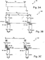
- FIG. 3A is a timing diagram illustrating a baseline or intrinsic sinus rhythm of heart H if no PESP therapy is delivered.
- Timing diagram 99 includes sensed atrial events A s1 and A S2 and sensed ventricular events V S1 and V S2 .
- Sensed atrial events A S1 and A S2 are generically used to describe atrial activity, but may be the result of paced pulses provided by IMD 10 to right atrium RA.
- sensed ventricular events V S1 and V S2 are generically used to describe ventricular activity, but may be the result of paced pulses provided by IMD 10 to right ventricle RV. These terms are also used to describe atrial and ventricular events in FIGS. 3B and 3C .
- the time between successive sensed atrial events is typically controlled by a sino-atrial (SA) node of heart H.
- SA sino-atrial
- the SA node automatically causes a depolarization within the SA node that is conducted through right atrium RA at time T0 following a previous SA node depolarization. If SA node does not depolarize automatically, a paced atrial pulse can be provided by IMD 10 at a programmed lower rate interval (LRI).
- LRI programmed lower rate interval
- the mechanical rate of heart H commonly describe as the heart rate, is defined by the time T0 between successive sensed atrial events A S1 and A S2 , and in turn the time (approximately equal to time T0) between successive sensed ventricular events V S1 and V S2 .
- the SA node automatically maintains time interval. T0 at approximately 800 milliseconds (ms), which results in a mechanical rate of heart H of approximately 75 beats per minute (bpm) in heart H.
- T0 milliseconds
- bpm beats per minute
- FIGS. 3B and 3C are timing diagrams illustrating delivery of PESP.
- Delivery of PESP requires IMD 10 to deliver premature pacing pulses A PESP or V PESP (A PESP and V PESP denote pulses delivered as part of PESP therapy) following a sensed or paced event.
- Pacing pulses are delivered by IMD 10 via output pulse generators 68 and 78 to RA lead 16 and RV lead 18, respectively.
- Timing diagram 100 includes sensed atrial events A S3 and A S4 , premature atrial pulses A PESP1 and A PESP2 , ventricular sensed events V S3 and V S4 , and premature ventricular pulses V PESP1 and V PESP2 .
- Atrial refractory period (RP) following sensed atrial events A S3 and A S4 is shown by shaded regions 102 and 104, respectively.
- Ventricular refractory period (RP) following sensed ventricular events V S3 and V S4 is shown by shaded regions 106 and 108, respectively.
- IMD 10 times delivery of premature atrial pulse A PESP1 based on sensed atrial event A S3 .
- Premature atrial pulse A PESP1 must be delivered outside of atrial RP 102, such that premature atrial pulse A PESP1 is able to cause a depolarization, and therefore, contraction of right atrium RA. Furthermore, by providing premature atrial pulse A PESP1 close in time with sensed atrial event A S3 , the potentiation provided to right atrium RA is maximized.
- premature atrial pulse A PESP1 is delivered at a time interval T1 following sensed atrial event A S3 .
- Premature atrial pulse A PESP2 is also delivered outside of atrial RP 104 following sensed atrial event A S4 .
- IMD 10 times delivery of premature ventricular pulse V PESP1 based on sensed ventricular event V S3 .
- Premature ventricular pulse V PESP1 must also be delivered outside of ventricular RP 106, such that premature ventricular pulse V PESP1 is able to cause a depolarization, and therefore, contraction of right ventricular RV.
- Providing premature ventricular pulse V PESP1 close in time with sensed ventricular event V S3 maximizes the potentiation benefits to right ventricle RV.
- premature ventricular pulse V PESP1 is delivered at a time interval T2 following sensed ventricular event V S3 .
- Time interval T2 may or may not be equal to time interval T1, depending on the refractory periods associated with right atrium RA and light ventricle RV.
- the mechanical rate of heart H is a function of the time T3 between successive sensed atrial events A S3 and A S4 , and in turn the time (approximately equal to time T3) between successive sensed ventricular events V S3 and V S4 .
- Premature atrial and ventricular paced pulses A PESP1 and V PESP1 do not cause either right atrium RA or right ventricle RV to expel blood from the respective chambers, and thus do not directly effect the mechanical rate of heart H.
- premature atrial pulses can potentially decrease the mechanical rate of heart H by depolarizing and in effect resetting the SA node of heart H.
- the time between successive sensed atrial events is typically controlled by the SA node of heart H, which automatically causes a depolarization of the atrium at a defined time interval (i.e., time interval TO as shown in FIG. 3A ) following a previous depolarizations of the SA node.
- a defined time interval i.e., time interval TO as shown in FIG. 3A
- time interval T4 the time interval defined by the SA node is shown as time interval T4, which is approximately equal to time interval TO as shown in FIG. 3A .
- This has the effect of extending the time between sensed atrial events A S3 and A S4 with respect to the intrinsic sinus rhythm shown in FIG. 3A , resulting in a decrease in the mechanical rate or heartbeat of a patient.
- time interval T3 is also minimized and the mechanical rate of heart H is maintained as close as possible to the intrinsic sinus rhythm.
- premature atrial paces i.e., A PESP1 and A PESP2
- sensed atrial events i.e., A S3 and A S4 , respectively
- atrial refractory periods i.e., atrial RP 102 and 104, respectively
- Timing diagram 110 shown in FIG. 3B illustrates delivery of PESP therapy without directly affecting the mechanical rate or heartbeat of heart H.
- Timing diagram 110 includes sensed atrial events A S5 and A S6 , premature atrial pulses A PESP3 and A PESP4 , ventricular sensed events V S5 and V S6 , and premature ventricular pulses V PESP3 and V PESP4 .
- Atrial refractory period (RP) following sensed atrial events A S5 and A S6 is divided into SA node RP 112 and 114, respectively, and non-nodal atrial RP 116 and 118, respectively.
- the SA node RP (as shown by RP 112 and 114) is longer than the non-nodal atrial RP (as shown by 116 and 118), as shown in FIG. 3B . If this situation exists, then IMD 10 delivers premature atrial pulse A PESP3 outside of non-nodal atrial RP 116, but within SA node RP 112, at time interval T5 following atrial sensed event A S5 . Delivering premature atrial pulse A PESP3 within this window provides the desired atrial potentiation effects in right atrium RA without depolarizing and therefore resettling the SA node.
- the benefit of delivering premature atrial pulse A PESP3 during the SA node RP 112, is the SA node generates sensed atrial event A S6 at time period T6 following sensed atrial event A S5 , which is approximately equal to the intrinsic sinus rhythm Illustrated by time interval TO in FIG. 3A . If time interval T6 is approximately equal to time period TO, then the mechanical rate af heart H is maintained at a rate determined by the SA node.
- premature ventricular pulses V PESP3 and V PESP4 are delivered at time period T7 following sensed ventricular events V S3 and V S6 , outside of ventricular RPs 120 and 122, providing maximum potentiation benefits to right ventricle RV.
- FIG. 3C illustrates PESP therapy in which IMD 10 times delivery of a premature atrial pulse within a window defined by the sino-atrial refractory period and the non-nodal refractory period. This provides potentiation benefits to the atrium and allows the sino-atrial node to maintain direct control of the mechanical heart rate at a rate approximately equal to the intrinsic rhythm rate (i.e., time interval T6 ⁇ time interval T0).
- IMD 10 in order to deliver properly timed premature atrial and ventricular pulses, IMD 10 must determine the length of refractory periods following atrial and ventricular sensed events. In one embodiment, IMD 10 delivers a premature atrial pulse at a first initial time interval following a sensed atrial event, and delivers premature ventricular pulse at a second initial time interval following a sensed ventricular event. IMD 10 determines whether either the premature atrial pulse or the premature ventricular pulse caused a depolarization and therefore contraction of either the right atrium or right ventricle.
- IMD 10 lengthens the first initial time interval and delivers another premature atrial pulse following the next atrial sensed event. This process is continued until a proper timing interval is determined (i.e., outside of the atrial refractory period but close in time with the atrial sensed event). The same process is performed with respect to the premature ventricular pulses delivered by IMD 10.
- IMD 10 In order to determine whether a premature atrial pulse is properly timed within the window defined by the SA node RP and the non-nodal RP (as shown in FIG. 3C ), IMD 10 provides a premature atrial pace and either shortens or lengthens the time interval associated with the premature atrial pace based on the sensed response. For example, IMD 10 delivers a first premature atrial pace following a first sensed atrial event, resulting in a depolarization of the atrium and a time interval between the first sensed atrial event and a second sensed atrial event greater than the intrinsic sinus rate.
- IMD 10 determines that the first premature atrial pace was delivered outside of both the SA node refractory period and the non-nodal refractory period. In response, IMD 10 shortens the interval between the second or subsequent sensed atrial event and a second premature atrial pace. If the second Premature atrial pace results in a depolarization of the atrium, along with a time interval between the second sensed atrial event and the third sensed atrial event approximately equal to the intrinsic rhythm rate of heart H, then IMD 10 determines that the second premature atrial pace was delivered within the window defined by the SA node refractory period and the non-nodal refractory period. Subsequent premature atrial paces will be delivered at the same interval.
- IMD 10 provides PESP therapy to the right atrium RA based on atrial sensed events and provides PESP therapy to the right ventricle RV based on ventricular sensed events.
- Providing PESP therapy in this manner provides maximum potentiation benefit to both the right atrium RA and right ventricle RV.
- providing PESP therapy in this manner minimizes decreases in the mechanical rate of heart H.
- PESP therapy is implemented in multi-chamber IMD to allow the IMD to deliver premature pacing pulses to the left atrium LA and left ventricle, LV, based on sensed activity in the left atrium LA and left ventricle LV, respectively.
Landscapes
- Health & Medical Sciences (AREA)
- Cardiology (AREA)
- Hospice & Palliative Care (AREA)
- Heart & Thoracic Surgery (AREA)
- Engineering & Computer Science (AREA)
- Biomedical Technology (AREA)
- Nuclear Medicine, Radiotherapy & Molecular Imaging (AREA)
- Radiology & Medical Imaging (AREA)
- Life Sciences & Earth Sciences (AREA)
- Animal Behavior & Ethology (AREA)
- General Health & Medical Sciences (AREA)
- Public Health (AREA)
- Veterinary Medicine (AREA)
- Electrotherapy Devices (AREA)
Claims (5)
- Herzschrittmachervorrichtung, die aufweist:eine Vorhofzuleitung bzw. -leitung (16) zum Erfassen einer elektrischen Aktivität in einem Vorhof und zum Verabreichen von elektrischen Impulsen an den Vorhof;eine Herzkammerzuleitung (18) zum Erfassen einer elektrischen Aktivität in einer Herzkammer und zum Verabreichen von elektrischen Impulsen an die Herzkammer;eine Erfassungsschaltungsanordnung (72), die mit der Vorhof- und der Herzkammerzuleitung verbunden ist, zum Erfassen von Depolarisationen im Vorhof bzw. in der Herzkammer;eine Impulserzeugungsschaltungsanordnung (68), die mit der Vorhof- und der Herzkammerzuleitung verbunden ist, zum Verabreichen von Schrittmacherimpulsen an den Vorhof bzw. an die Herzkammer; undeine Steuerschaltungsanordnung (66) zum Empfangen von erfassten Vorhof- und Herzkammerdepolarisationen von der Erfassungsschaltungsanordnung und zum Steuern der Impulserzeugungsschaltungsanordnung in einem Modus, in dem die Impulserzeugungsschaltungsanordnung einen frühzeitigen Vorhofimpuls auf der Basis einer durch die Erfassungsschaltungsanordnung erfassten vorherigen Vorhofdepolarisation verabreicht und einen frühzeitigen Herzkammerimpuls auf der Basis einer durch die Erfassungsschaltungsanordnung erfassten vorherigen Herzkammerdepolarisation verabreicht, wobei die Steuerschaltungsanordnung die Impulserzeugungsschaltungsanordnung steuert, um den frühzeitigen Vorhofimpuls in einem ersten Zeitintervall nach der vorherigen Vorhofdepolarisation zuzuführen, wobei der frühzeitige Vorhofimpuls außerhalb einer Vorhofrefraktärperiode zugeführt wird, die der vorherigen Vorhofdepolarisation zugeordnet ist, und wobei der frühzeitige Vorhofimpuls innerhalb einer Sinusknotenrefraktärperiode zugeführt wird, die der vorherigen Vorhofdepolarisation zugeordnet ist; dadurch gekennzeichnet, dass die Steuerschaltungsanordnung (66) feststellt, ob ein drittes Zeitintervall zwischen der vorherigen Vorhofdepolarisation und einer folgenden Vorhofdepolarisation größer ist als ein intrinsischer Sinusrhythmus, wobei dann, wenn das dritte Zeitintervall größer ist als der intrinsische Sinusrhythmus, die Steuerschaltungsanordnung die Impulserzeugungsschaltungsanordnung steuert, um einen anschließenden frühzeitigen Vorhofimpuls in einem vierten Zeitintervall nach der anschließenden Vorhofdepolarisation zu verabreichen, wobei das vierte Zeitintervall kleiner ist als das erste Zeitintervall.
- Herzschrittmachervorrichtung nach Anspruch 1, wobei die Steuerschaltungsanordnung feststellt, ob der frühzeitige Vorhofimpuls eine Depolarisation im Vorhof verursacht hat, wobei dann, wenn der frühzeitige Vorhofimpuls keine Depolarisation verursacht hat, die Steuerschaltungsanordnung die Impulserzeugungsschaltung steuert, um einen anschließenden frühzeitigen Vorhofimpuls in einem zweiten Zeitintervall nach einer anschließenden Vorhofdepolarisation zuzuführen, wobei das zweite Zeitintervall größer ist als das erste Zeitintervall.
- Herzschrittmachervorrichtung nach Anspruch 1, wobei die Steuerschaltungsanordnung die Impulserzeugungsschaltungsanordnung steuert, um den frühzeitigen Herzkammerimpuls in einem fünften Zeitintervall nach der vorherigen Herzkammerdepolarisation zu verabreichen, wobei der frühzeitige Herzkammerimpuls außerhalb einer Herzkammerrefraktärperiode verabreicht wird, die der vorherigen Herzkammerdepolarisation zugeordnet ist.
- Herzschrittmachervorrichtung nach Anspruch 3, wobei die Steuerschaltungsanordnung feststellt, ob der frühzeitige Herzkammerimpuls eine Depolarisation in der Herzkammer verursacht hat, wobei dann, wenn der frühzeitige Herzkammerimpuls keine Depolarisation verursacht hat, die Steuerschaltungsanordnung die Impulserzeugungsschaltungsanordnung steuert, um einen anschließenden frühzeitigen Herzkammerimpuls in einem sechsten Zeitintervall nach einer anschließenden Herzkammerdepolarisation zu verabreichen, wobei das sechste Zeitintervall größer ist als das fünfte Zeitintervall.
- Herzschrittmachervorrichtung nach Anspruch 1 oder 2, wobei die Steuerschaltungsanordnung das erste Zeitintervall so auswählt, dass es größer ist als eine knotenfreie Vorhofrefraktärperiode, die durch die von der Erfassungsschaltungsanordnung erfasste vorherige Vorhofdepolarisation verursacht wird.
Applications Claiming Priority (2)
| Application Number | Priority Date | Filing Date | Title |
|---|---|---|---|
| US11/322,856 US7599739B2 (en) | 2005-12-30 | 2005-12-30 | Multi-chamber timing for premature cardiac pacing |
| PCT/US2006/062063 WO2007079336A2 (en) | 2005-12-30 | 2006-12-14 | Multi-chamber timing for premature cardiac pacing |
Publications (2)
| Publication Number | Publication Date |
|---|---|
| EP1979047A2 EP1979047A2 (de) | 2008-10-15 |
| EP1979047B1 true EP1979047B1 (de) | 2012-04-25 |
Family
ID=38225529
Family Applications (1)
| Application Number | Title | Priority Date | Filing Date |
|---|---|---|---|
| EP06840254A Not-in-force EP1979047B1 (de) | 2005-12-30 | 2006-12-14 | Mehrkammertakt für frühe schrittmachersteuerung |
Country Status (4)
| Country | Link |
|---|---|
| US (1) | US7599739B2 (de) |
| EP (1) | EP1979047B1 (de) |
| AT (1) | ATE554823T1 (de) |
| WO (1) | WO2007079336A2 (de) |
Families Citing this family (3)
| Publication number | Priority date | Publication date | Assignee | Title |
|---|---|---|---|---|
| US20060178705A1 (en) * | 2005-02-10 | 2006-08-10 | Paul Janssen | Heart rate variance cardiac pacemaker |
| US8818510B2 (en) * | 2007-10-30 | 2014-08-26 | Pacesetter, Inc. | Systems and methods for paired/coupled pacing |
| US8768461B2 (en) * | 2011-09-06 | 2014-07-01 | Pacesetter, Inc. | Systems and methods for controlling paired pacing interpulse intervals to reduce contractility disequilibrium using an implantable medical device |
Citations (1)
| Publication number | Priority date | Publication date | Assignee | Title |
|---|---|---|---|---|
| WO2003020364A2 (en) * | 2001-08-28 | 2003-03-13 | Medtronic, Inc. | Implantable medical device for treating cardiac mechanical dysfunction by electrical stimulation |
Family Cites Families (9)
| Publication number | Priority date | Publication date | Assignee | Title |
|---|---|---|---|---|
| US5213098A (en) * | 1991-07-26 | 1993-05-25 | Medtronic, Inc. | Post-extrasystolic potentiation stimulation with physiologic sensor feedback |
| US6496730B1 (en) * | 1998-12-29 | 2002-12-17 | Medtronic, Inc. | Multi-site cardiac pacing system having conditional refractory period |
| US20040220636A1 (en) * | 2003-04-29 | 2004-11-04 | Medtronic, Inc. | Cardiac pacing therapy parameter programming |
| US20040220640A1 (en) * | 2003-04-29 | 2004-11-04 | Medtronic, Inc. | Method and apparatus for determining myocardial electrical resitution and controlling extra systolic stimulation |
| US20040220631A1 (en) * | 2003-04-29 | 2004-11-04 | Medtronic, Inc. | Method and apparatus for detecting myocardial electrical recovery and controlling extra-systolic sstimulation |
| US7142916B2 (en) * | 2003-10-07 | 2006-11-28 | Medtronic, Inc. | Cardiac pacing modality having improved blanking, timing, and therapy delivery methods for extra-systolic stimulation pacing therapy |
| US20060173498A1 (en) * | 2005-01-31 | 2006-08-03 | Isabelle Banville | Communication between an external defibrillator and an implantable medical device |
| US7289850B2 (en) * | 2005-04-28 | 2007-10-30 | Medtronics, Inc. | System for enhanced cardiac function with combined PESP/NES |
| US20060247698A1 (en) | 2005-04-28 | 2006-11-02 | Burnes John E | Multi-site PESP with fusion pacing |
-
2005
- 2005-12-30 US US11/322,856 patent/US7599739B2/en not_active Expired - Fee Related
-
2006
- 2006-12-14 EP EP06840254A patent/EP1979047B1/de not_active Not-in-force
- 2006-12-14 WO PCT/US2006/062063 patent/WO2007079336A2/en not_active Ceased
- 2006-12-14 AT AT06840254T patent/ATE554823T1/de active
Patent Citations (1)
| Publication number | Priority date | Publication date | Assignee | Title |
|---|---|---|---|---|
| WO2003020364A2 (en) * | 2001-08-28 | 2003-03-13 | Medtronic, Inc. | Implantable medical device for treating cardiac mechanical dysfunction by electrical stimulation |
Also Published As
| Publication number | Publication date |
|---|---|
| ATE554823T1 (de) | 2012-05-15 |
| EP1979047A2 (de) | 2008-10-15 |
| WO2007079336A2 (en) | 2007-07-12 |
| US7599739B2 (en) | 2009-10-06 |
| US20070156192A1 (en) | 2007-07-05 |
| WO2007079336A3 (en) | 2007-10-04 |
Similar Documents
| Publication | Publication Date | Title |
|---|---|---|
| US6334071B1 (en) | Minute volume pacemakers that require only a single distal electrode | |
| US8718768B2 (en) | Pace counter isolation for cardiac resynchronization pacing | |
| US8103334B2 (en) | Method and system for display of cardiac event intervals in a resynchronization pacemaker | |
| EP2015839B1 (de) | Implantierbare medizinische vorrichtung mit elektromechanischer verzögerungsmessung für elektrodenposition und beurteilung von ventrikulärer dyssynchronie | |
| US8473053B2 (en) | Minimum ventricular pacing to break the repetitive AR-VS pattern | |
| US8126551B2 (en) | AV delay features | |
| WO1995032758A1 (en) | Dual chamber pacing with atrial and ventricular independence | |
| EP2432551B1 (de) | Implantierbare medizinische vorrichtung kardiale elektrostimulation | |
| US7835792B2 (en) | Implantable cardiac device | |
| US7689279B2 (en) | Pacing device for minimizing ventricular pauses after delivery of atrial anti-tachycardia pacing therapy | |
| US7647103B2 (en) | Addressing pacemaker syndrome | |
| EP1979047B1 (de) | Mehrkammertakt für frühe schrittmachersteuerung | |
| US7672723B2 (en) | Implantable medical device for biventricular stimulation | |
| EP4448085B1 (de) | System mit mindestens zwei vorrichtungen |
Legal Events
| Date | Code | Title | Description |
|---|---|---|---|
| PUAI | Public reference made under article 153(3) epc to a published international application that has entered the european phase |
Free format text: ORIGINAL CODE: 0009012 |
|
| 17P | Request for examination filed |
Effective date: 20080728 |
|
| AK | Designated contracting states |
Kind code of ref document: A2 Designated state(s): AT BE BG CH CY CZ DE DK EE ES FI FR GB GR HU IE IS IT LI LT LU LV MC NL PL PT RO SE SI SK TR |
|
| 17Q | First examination report despatched |
Effective date: 20091214 |
|
| GRAP | Despatch of communication of intention to grant a patent |
Free format text: ORIGINAL CODE: EPIDOSNIGR1 |
|
| DAX | Request for extension of the european patent (deleted) | ||
| GRAS | Grant fee paid |
Free format text: ORIGINAL CODE: EPIDOSNIGR3 |
|
| GRAA | (expected) grant |
Free format text: ORIGINAL CODE: 0009210 |
|
| AK | Designated contracting states |
Kind code of ref document: B1 Designated state(s): AT BE BG CH CY CZ DE DK EE ES FI FR GB GR HU IE IS IT LI LT LU LV MC NL PL PT RO SE SI SK TR |
|
| REG | Reference to a national code |
Ref country code: GB Ref legal event code: FG4D |
|
| REG | Reference to a national code |
Ref country code: CH Ref legal event code: EP |
|
| REG | Reference to a national code |
Ref country code: AT Ref legal event code: REF Ref document number: 554823 Country of ref document: AT Kind code of ref document: T Effective date: 20120515 |
|
| REG | Reference to a national code |
Ref country code: IE Ref legal event code: FG4D |
|
| REG | Reference to a national code |
Ref country code: DE Ref legal event code: R096 Ref document number: 602006029148 Country of ref document: DE Effective date: 20120628 |
|
| REG | Reference to a national code |
Ref country code: NL Ref legal event code: VDEP Effective date: 20120425 |
|
| REG | Reference to a national code |
Ref country code: AT Ref legal event code: MK05 Ref document number: 554823 Country of ref document: AT Kind code of ref document: T Effective date: 20120425 |
|
| LTIE | Lt: invalidation of european patent or patent extension |
Effective date: 20120425 |
|
| PG25 | Lapsed in a contracting state [announced via postgrant information from national office to epo] |
Ref country code: LT Free format text: LAPSE BECAUSE OF FAILURE TO SUBMIT A TRANSLATION OF THE DESCRIPTION OR TO PAY THE FEE WITHIN THE PRESCRIBED TIME-LIMIT Effective date: 20120425 Ref country code: SE Free format text: LAPSE BECAUSE OF FAILURE TO SUBMIT A TRANSLATION OF THE DESCRIPTION OR TO PAY THE FEE WITHIN THE PRESCRIBED TIME-LIMIT Effective date: 20120425 Ref country code: CY Free format text: LAPSE BECAUSE OF FAILURE TO SUBMIT A TRANSLATION OF THE DESCRIPTION OR TO PAY THE FEE WITHIN THE PRESCRIBED TIME-LIMIT Effective date: 20120425 Ref country code: IS Free format text: LAPSE BECAUSE OF FAILURE TO SUBMIT A TRANSLATION OF THE DESCRIPTION OR TO PAY THE FEE WITHIN THE PRESCRIBED TIME-LIMIT Effective date: 20120825 Ref country code: FI Free format text: LAPSE BECAUSE OF FAILURE TO SUBMIT A TRANSLATION OF THE DESCRIPTION OR TO PAY THE FEE WITHIN THE PRESCRIBED TIME-LIMIT Effective date: 20120425 Ref country code: PL Free format text: LAPSE BECAUSE OF FAILURE TO SUBMIT A TRANSLATION OF THE DESCRIPTION OR TO PAY THE FEE WITHIN THE PRESCRIBED TIME-LIMIT Effective date: 20120425 |
|
| PG25 | Lapsed in a contracting state [announced via postgrant information from national office to epo] |
Ref country code: LV Free format text: LAPSE BECAUSE OF FAILURE TO SUBMIT A TRANSLATION OF THE DESCRIPTION OR TO PAY THE FEE WITHIN THE PRESCRIBED TIME-LIMIT Effective date: 20120425 Ref country code: PT Free format text: LAPSE BECAUSE OF FAILURE TO SUBMIT A TRANSLATION OF THE DESCRIPTION OR TO PAY THE FEE WITHIN THE PRESCRIBED TIME-LIMIT Effective date: 20120827 Ref country code: GR Free format text: LAPSE BECAUSE OF FAILURE TO SUBMIT A TRANSLATION OF THE DESCRIPTION OR TO PAY THE FEE WITHIN THE PRESCRIBED TIME-LIMIT Effective date: 20120726 Ref country code: SI Free format text: LAPSE BECAUSE OF FAILURE TO SUBMIT A TRANSLATION OF THE DESCRIPTION OR TO PAY THE FEE WITHIN THE PRESCRIBED TIME-LIMIT Effective date: 20120425 |
|
| PG25 | Lapsed in a contracting state [announced via postgrant information from national office to epo] |
Ref country code: BE Free format text: LAPSE BECAUSE OF FAILURE TO SUBMIT A TRANSLATION OF THE DESCRIPTION OR TO PAY THE FEE WITHIN THE PRESCRIBED TIME-LIMIT Effective date: 20120425 |
|
| PG25 | Lapsed in a contracting state [announced via postgrant information from national office to epo] |
Ref country code: EE Free format text: LAPSE BECAUSE OF FAILURE TO SUBMIT A TRANSLATION OF THE DESCRIPTION OR TO PAY THE FEE WITHIN THE PRESCRIBED TIME-LIMIT Effective date: 20120425 Ref country code: NL Free format text: LAPSE BECAUSE OF FAILURE TO SUBMIT A TRANSLATION OF THE DESCRIPTION OR TO PAY THE FEE WITHIN THE PRESCRIBED TIME-LIMIT Effective date: 20120425 Ref country code: DK Free format text: LAPSE BECAUSE OF FAILURE TO SUBMIT A TRANSLATION OF THE DESCRIPTION OR TO PAY THE FEE WITHIN THE PRESCRIBED TIME-LIMIT Effective date: 20120425 Ref country code: SK Free format text: LAPSE BECAUSE OF FAILURE TO SUBMIT A TRANSLATION OF THE DESCRIPTION OR TO PAY THE FEE WITHIN THE PRESCRIBED TIME-LIMIT Effective date: 20120425 Ref country code: CZ Free format text: LAPSE BECAUSE OF FAILURE TO SUBMIT A TRANSLATION OF THE DESCRIPTION OR TO PAY THE FEE WITHIN THE PRESCRIBED TIME-LIMIT Effective date: 20120425 Ref country code: RO Free format text: LAPSE BECAUSE OF FAILURE TO SUBMIT A TRANSLATION OF THE DESCRIPTION OR TO PAY THE FEE WITHIN THE PRESCRIBED TIME-LIMIT Effective date: 20120425 Ref country code: AT Free format text: LAPSE BECAUSE OF FAILURE TO SUBMIT A TRANSLATION OF THE DESCRIPTION OR TO PAY THE FEE WITHIN THE PRESCRIBED TIME-LIMIT Effective date: 20120425 |
|
| PG25 | Lapsed in a contracting state [announced via postgrant information from national office to epo] |
Ref country code: IT Free format text: LAPSE BECAUSE OF FAILURE TO SUBMIT A TRANSLATION OF THE DESCRIPTION OR TO PAY THE FEE WITHIN THE PRESCRIBED TIME-LIMIT Effective date: 20120425 |
|
| PLBE | No opposition filed within time limit |
Free format text: ORIGINAL CODE: 0009261 |
|
| STAA | Information on the status of an ep patent application or granted ep patent |
Free format text: STATUS: NO OPPOSITION FILED WITHIN TIME LIMIT |
|
| 26N | No opposition filed |
Effective date: 20130128 |
|
| PG25 | Lapsed in a contracting state [announced via postgrant information from national office to epo] |
Ref country code: ES Free format text: LAPSE BECAUSE OF FAILURE TO SUBMIT A TRANSLATION OF THE DESCRIPTION OR TO PAY THE FEE WITHIN THE PRESCRIBED TIME-LIMIT Effective date: 20120805 |
|
| REG | Reference to a national code |
Ref country code: DE Ref legal event code: R097 Ref document number: 602006029148 Country of ref document: DE Effective date: 20130128 |
|
| PG25 | Lapsed in a contracting state [announced via postgrant information from national office to epo] |
Ref country code: BG Free format text: LAPSE BECAUSE OF FAILURE TO SUBMIT A TRANSLATION OF THE DESCRIPTION OR TO PAY THE FEE WITHIN THE PRESCRIBED TIME-LIMIT Effective date: 20120725 Ref country code: MC Free format text: LAPSE BECAUSE OF NON-PAYMENT OF DUE FEES Effective date: 20121231 |
|
| REG | Reference to a national code |
Ref country code: CH Ref legal event code: PL |
|
| GBPC | Gb: european patent ceased through non-payment of renewal fee |
Effective date: 20121214 |
|
| REG | Reference to a national code |
Ref country code: IE Ref legal event code: MM4A |
|
| PG25 | Lapsed in a contracting state [announced via postgrant information from national office to epo] |
Ref country code: IE Free format text: LAPSE BECAUSE OF NON-PAYMENT OF DUE FEES Effective date: 20121214 Ref country code: CH Free format text: LAPSE BECAUSE OF NON-PAYMENT OF DUE FEES Effective date: 20121231 Ref country code: LI Free format text: LAPSE BECAUSE OF NON-PAYMENT OF DUE FEES Effective date: 20121231 |
|
| PG25 | Lapsed in a contracting state [announced via postgrant information from national office to epo] |
Ref country code: GB Free format text: LAPSE BECAUSE OF NON-PAYMENT OF DUE FEES Effective date: 20121214 |
|
| PGFP | Annual fee paid to national office [announced via postgrant information from national office to epo] |
Ref country code: DE Payment date: 20131230 Year of fee payment: 8 |
|
| PGFP | Annual fee paid to national office [announced via postgrant information from national office to epo] |
Ref country code: FR Payment date: 20131217 Year of fee payment: 8 |
|
| PG25 | Lapsed in a contracting state [announced via postgrant information from national office to epo] |
Ref country code: TR Free format text: LAPSE BECAUSE OF FAILURE TO SUBMIT A TRANSLATION OF THE DESCRIPTION OR TO PAY THE FEE WITHIN THE PRESCRIBED TIME-LIMIT Effective date: 20120425 |
|
| PG25 | Lapsed in a contracting state [announced via postgrant information from national office to epo] |
Ref country code: LU Free format text: LAPSE BECAUSE OF NON-PAYMENT OF DUE FEES Effective date: 20121214 |
|
| PG25 | Lapsed in a contracting state [announced via postgrant information from national office to epo] |
Ref country code: HU Free format text: LAPSE BECAUSE OF FAILURE TO SUBMIT A TRANSLATION OF THE DESCRIPTION OR TO PAY THE FEE WITHIN THE PRESCRIBED TIME-LIMIT Effective date: 20061214 |
|
| REG | Reference to a national code |
Ref country code: DE Ref legal event code: R119 Ref document number: 602006029148 Country of ref document: DE |
|
| REG | Reference to a national code |
Ref country code: FR Ref legal event code: ST Effective date: 20150831 |
|
| PG25 | Lapsed in a contracting state [announced via postgrant information from national office to epo] |
Ref country code: DE Free format text: LAPSE BECAUSE OF NON-PAYMENT OF DUE FEES Effective date: 20150701 |
|
| PG25 | Lapsed in a contracting state [announced via postgrant information from national office to epo] |
Ref country code: FR Free format text: LAPSE BECAUSE OF NON-PAYMENT OF DUE FEES Effective date: 20141231 |