EP1978790B1 - Vorrichtung und Verfahren zum Beschichten eines Bauteils mit Justiereinrichtung - Google Patents
Vorrichtung und Verfahren zum Beschichten eines Bauteils mit Justiereinrichtung Download PDFInfo
- Publication number
- EP1978790B1 EP1978790B1 EP07006095A EP07006095A EP1978790B1 EP 1978790 B1 EP1978790 B1 EP 1978790B1 EP 07006095 A EP07006095 A EP 07006095A EP 07006095 A EP07006095 A EP 07006095A EP 1978790 B1 EP1978790 B1 EP 1978790B1
- Authority
- EP
- European Patent Office
- Prior art keywords
- coating
- reference plate
- component
- process according
- coated
- Prior art date
- Legal status (The legal status is an assumption and is not a legal conclusion. Google has not performed a legal analysis and makes no representation as to the accuracy of the status listed.)
- Not-in-force
Links
- 238000000576 coating method Methods 0.000 title claims abstract description 69
- 239000011248 coating agent Substances 0.000 title claims abstract description 57
- 238000000034 method Methods 0.000 title claims abstract description 32
- 238000011156 evaluation Methods 0.000 claims abstract description 9
- 239000000463 material Substances 0.000 claims description 29
- 238000007750 plasma spraying Methods 0.000 claims description 4
- 238000007749 high velocity oxygen fuel spraying Methods 0.000 claims description 3
- 238000010288 cold spraying Methods 0.000 claims 1
- 238000005286 illumination Methods 0.000 claims 1
- 238000005507 spraying Methods 0.000 abstract description 2
- 230000003287 optical effect Effects 0.000 abstract 1
- 238000002485 combustion reaction Methods 0.000 description 16
- 239000010410 layer Substances 0.000 description 12
- PXHVJJICTQNCMI-UHFFFAOYSA-N Nickel Chemical compound [Ni] PXHVJJICTQNCMI-UHFFFAOYSA-N 0.000 description 11
- 239000007921 spray Substances 0.000 description 11
- 239000012720 thermal barrier coating Substances 0.000 description 10
- 229910045601 alloy Inorganic materials 0.000 description 5
- 239000000956 alloy Substances 0.000 description 5
- 229910017052 cobalt Inorganic materials 0.000 description 5
- 239000010941 cobalt Substances 0.000 description 5
- GUTLYIVDDKVIGB-UHFFFAOYSA-N cobalt atom Chemical compound [Co] GUTLYIVDDKVIGB-UHFFFAOYSA-N 0.000 description 5
- 239000013078 crystal Substances 0.000 description 5
- 238000005260 corrosion Methods 0.000 description 4
- 229910052759 nickel Inorganic materials 0.000 description 4
- 229910000601 superalloy Inorganic materials 0.000 description 4
- XEEYBQQBJWHFJM-UHFFFAOYSA-N Iron Chemical compound [Fe] XEEYBQQBJWHFJM-UHFFFAOYSA-N 0.000 description 3
- BRPQOXSCLDDYGP-UHFFFAOYSA-N calcium oxide Chemical compound [O-2].[Ca+2] BRPQOXSCLDDYGP-UHFFFAOYSA-N 0.000 description 3
- 239000000292 calcium oxide Substances 0.000 description 3
- ODINCKMPIJJUCX-UHFFFAOYSA-N calcium oxide Inorganic materials [Ca]=O ODINCKMPIJJUCX-UHFFFAOYSA-N 0.000 description 3
- 238000001816 cooling Methods 0.000 description 3
- 230000007797 corrosion Effects 0.000 description 3
- 238000005566 electron beam evaporation Methods 0.000 description 3
- 229910052735 hafnium Inorganic materials 0.000 description 3
- VBJZVLUMGGDVMO-UHFFFAOYSA-N hafnium atom Chemical compound [Hf] VBJZVLUMGGDVMO-UHFFFAOYSA-N 0.000 description 3
- 239000000395 magnesium oxide Substances 0.000 description 3
- CPLXHLVBOLITMK-UHFFFAOYSA-N magnesium oxide Inorganic materials [Mg]=O CPLXHLVBOLITMK-UHFFFAOYSA-N 0.000 description 3
- AXZKOIWUVFPNLO-UHFFFAOYSA-N magnesium;oxygen(2-) Chemical compound [O-2].[Mg+2] AXZKOIWUVFPNLO-UHFFFAOYSA-N 0.000 description 3
- 239000000203 mixture Substances 0.000 description 3
- 230000003647 oxidation Effects 0.000 description 3
- 238000007254 oxidation reaction Methods 0.000 description 3
- 239000011241 protective layer Substances 0.000 description 3
- 229910052710 silicon Inorganic materials 0.000 description 3
- 239000010703 silicon Substances 0.000 description 3
- 239000007787 solid Substances 0.000 description 3
- 238000007711 solidification Methods 0.000 description 3
- 230000008023 solidification Effects 0.000 description 3
- 229910052727 yttrium Inorganic materials 0.000 description 3
- VWQVUPCCIRVNHF-UHFFFAOYSA-N yttrium atom Chemical compound [Y] VWQVUPCCIRVNHF-UHFFFAOYSA-N 0.000 description 3
- RUDFQVOCFDJEEF-UHFFFAOYSA-N yttrium(III) oxide Inorganic materials [O-2].[O-2].[O-2].[Y+3].[Y+3] RUDFQVOCFDJEEF-UHFFFAOYSA-N 0.000 description 3
- 230000005540 biological transmission Effects 0.000 description 2
- 238000005266 casting Methods 0.000 description 2
- 239000000919 ceramic Substances 0.000 description 2
- 239000011521 glass Substances 0.000 description 2
- 238000009434 installation Methods 0.000 description 2
- 238000009419 refurbishment Methods 0.000 description 2
- 238000005488 sandblasting Methods 0.000 description 2
- 230000035939 shock Effects 0.000 description 2
- 239000000126 substance Substances 0.000 description 2
- YPFNIPKMNMDDDB-UHFFFAOYSA-K 2-[2-[bis(carboxylatomethyl)amino]ethyl-(2-hydroxyethyl)amino]acetate;iron(3+) Chemical compound [Fe+3].OCCN(CC([O-])=O)CCN(CC([O-])=O)CC([O-])=O YPFNIPKMNMDDDB-UHFFFAOYSA-K 0.000 description 1
- 241000191291 Abies alba Species 0.000 description 1
- 229910000831 Steel Inorganic materials 0.000 description 1
- 239000008186 active pharmaceutical agent Substances 0.000 description 1
- 238000005524 ceramic coating Methods 0.000 description 1
- 239000002826 coolant Substances 0.000 description 1
- 230000001419 dependent effect Effects 0.000 description 1
- 238000009826 distribution Methods 0.000 description 1
- 239000012530 fluid Substances 0.000 description 1
- 238000005242 forging Methods 0.000 description 1
- 239000000446 fuel Substances 0.000 description 1
- 239000007788 liquid Substances 0.000 description 1
- 238000004519 manufacturing process Methods 0.000 description 1
- 239000000155 melt Substances 0.000 description 1
- 229910001092 metal group alloy Inorganic materials 0.000 description 1
- 239000007769 metal material Substances 0.000 description 1
- 238000003801 milling Methods 0.000 description 1
- TWNQGVIAIRXVLR-UHFFFAOYSA-N oxo(oxoalumanyloxy)alumane Chemical compound O=[Al]O[Al]=O TWNQGVIAIRXVLR-UHFFFAOYSA-N 0.000 description 1
- 238000010248 power generation Methods 0.000 description 1
- 238000004886 process control Methods 0.000 description 1
- 239000011253 protective coating Substances 0.000 description 1
- 230000001681 protective effect Effects 0.000 description 1
- 229910052761 rare earth metal Inorganic materials 0.000 description 1
- 150000002910 rare earth metals Chemical class 0.000 description 1
- 229910052706 scandium Inorganic materials 0.000 description 1
- SIXSYDAISGFNSX-UHFFFAOYSA-N scandium atom Chemical compound [Sc] SIXSYDAISGFNSX-UHFFFAOYSA-N 0.000 description 1
- 239000010959 steel Substances 0.000 description 1
- 230000035882 stress Effects 0.000 description 1
- 239000000758 substrate Substances 0.000 description 1
- 230000008646 thermal stress Effects 0.000 description 1
- 230000007704 transition Effects 0.000 description 1
- 239000012780 transparent material Substances 0.000 description 1
Images


Classifications
-
- C—CHEMISTRY; METALLURGY
- C23—COATING METALLIC MATERIAL; COATING MATERIAL WITH METALLIC MATERIAL; CHEMICAL SURFACE TREATMENT; DIFFUSION TREATMENT OF METALLIC MATERIAL; COATING BY VACUUM EVAPORATION, BY SPUTTERING, BY ION IMPLANTATION OR BY CHEMICAL VAPOUR DEPOSITION, IN GENERAL; INHIBITING CORROSION OF METALLIC MATERIAL OR INCRUSTATION IN GENERAL
- C23C—COATING METALLIC MATERIAL; COATING MATERIAL WITH METALLIC MATERIAL; SURFACE TREATMENT OF METALLIC MATERIAL BY DIFFUSION INTO THE SURFACE, BY CHEMICAL CONVERSION OR SUBSTITUTION; COATING BY VACUUM EVAPORATION, BY SPUTTERING, BY ION IMPLANTATION OR BY CHEMICAL VAPOUR DEPOSITION, IN GENERAL
- C23C4/00—Coating by spraying the coating material in the molten state, e.g. by flame, plasma or electric discharge
- C23C4/12—Coating by spraying the coating material in the molten state, e.g. by flame, plasma or electric discharge characterised by the method of spraying
-
- C—CHEMISTRY; METALLURGY
- C23—COATING METALLIC MATERIAL; COATING MATERIAL WITH METALLIC MATERIAL; CHEMICAL SURFACE TREATMENT; DIFFUSION TREATMENT OF METALLIC MATERIAL; COATING BY VACUUM EVAPORATION, BY SPUTTERING, BY ION IMPLANTATION OR BY CHEMICAL VAPOUR DEPOSITION, IN GENERAL; INHIBITING CORROSION OF METALLIC MATERIAL OR INCRUSTATION IN GENERAL
- C23C—COATING METALLIC MATERIAL; COATING MATERIAL WITH METALLIC MATERIAL; SURFACE TREATMENT OF METALLIC MATERIAL BY DIFFUSION INTO THE SURFACE, BY CHEMICAL CONVERSION OR SUBSTITUTION; COATING BY VACUUM EVAPORATION, BY SPUTTERING, BY ION IMPLANTATION OR BY CHEMICAL VAPOUR DEPOSITION, IN GENERAL
- C23C24/00—Coating starting from inorganic powder
- C23C24/02—Coating starting from inorganic powder by application of pressure only
- C23C24/04—Impact or kinetic deposition of particles
-
- Y—GENERAL TAGGING OF NEW TECHNOLOGICAL DEVELOPMENTS; GENERAL TAGGING OF CROSS-SECTIONAL TECHNOLOGIES SPANNING OVER SEVERAL SECTIONS OF THE IPC; TECHNICAL SUBJECTS COVERED BY FORMER USPC CROSS-REFERENCE ART COLLECTIONS [XRACs] AND DIGESTS
- Y02—TECHNOLOGIES OR APPLICATIONS FOR MITIGATION OR ADAPTATION AGAINST CLIMATE CHANGE
- Y02T—CLIMATE CHANGE MITIGATION TECHNOLOGIES RELATED TO TRANSPORTATION
- Y02T50/00—Aeronautics or air transport
- Y02T50/60—Efficient propulsion technologies, e.g. for aircraft
Definitions
- the invention relates to a device and a method for coating a component, in which the position of coating material sources and / or the component to be coated can be adjusted.
- a spray cone ie the distribution of the material, is checked to check the adjustment of nozzles. This is done by means of a steel plate, which is coated and must be removed from the coating system and controlled. Such a device is from the Patent US 4,358,471 known. This means an interruption of the coating process and a poor quality statement about the adjustment.
- the object is achieved by a device according to claim 1 and a method according to claim 8.
- FIG. 1 1 shows a coating system 1 according to the prior art, in which a component 4 to be coated is present in a holder 7.
- the component 4, 120, 130, 155 ( Fig. 6 . 7, 8 ) is coated by means of a coating material source 10, for example by means of a plasma nozzle (LPPS, APS, VPS,...), a nozzle of a HVOF coating unit or from a nozzle of a cold gas spraying unit or other material source (for example a PVD, CVD material source) ,
- LPPS plasma nozzle
- APS APS
- VPS vacuum nozzle
- a nozzle of a HVOF coating unit or from a nozzle of a cold gas spraying unit or other material source for example a PVD, CVD material source
- the coating material source 10 is moved into a position 13, which in FIG. 1 indicated by dashed lines. In this case, 16 coating material is applied to a reference plate.
- FIG. 2 This is taken from the coating installation 1 and can only be examined outside the coating installation 1.
- FIG. 2 shows, in which the coated reference plate 16 is present outside of the coating system 1.
- a coated surface 19 On the reference plate 16 is a coated surface 19, for example, a spray cone 19 is present, which may have deviations from a desired geometry 22 (dashed lines) of the spray cone. In case of deviations, for example, the coating material source 10 must be readjusted or replaced.
- FIG. 3 a device 40 according to the invention is shown, in addition to FIG. 1
- a reference plate 25 of a coatable material has a sensor 28.
- the reference plate 25 is not a part of the component to be coated 4, 120, 130, 155 ( Fig. 6 . 7, 8 ).
- the reference plate 25 can be examined in the coating system 10 without opening the coating device 40, in particular by a sensor 28.
- the reference plate 25 is optically examined, preferably, the reference plate 25 is made of glass.
- the reference plate 25 is preferably made of an optically transparent material, in particular of a glass.
- the reference plate 25 is preferably coated and examined prior to the start of the coating of the component 4, 120, 130. Also preferably, the reference plate 25 may preferably be additionally coated during and after the complete coating of the component 4, 120, 130, 155 and examined and a re-examination of the coating material source 10 is possible.
- the reference plate 25 may also preferably be replaced during the coating process within the device 40.
- the coating material source 10 is preferably moved into a position 13 (shown in dashed lines) and coated, so that a spray cone 19 is produced on the reference plate 25.
- the reference plate 25 can also be moved, that is, for example, moved and coated between the coating material source 10 and the component 4 (FIG. FIG. 4 ). Then it is preferably retracted and preferably examined in a different position.
- the front 26 or back 27 of the reference plate 25 can be examined by the sensor 28.
- the spray cone 19 is examined on the reference plate 25 within the system 40.
- the reference plate 25 is illuminated in a preferred embodiment of the sensor 28 and at the same time detects the reflection.
- the reference plate 25 can be illuminated by means of an exposure source 37, in which case the sensor 28 measures the transmission of the exposure source 37, so that the position of the spray cone 19 can be determined.
- the evaluation method of the coated reference plate 25 is based on FIG. 5 explained.
- the reference plate 25 is shown with a spray cone 19.
- the exposure source 37 emits beams 34 which can not reach the sensor 28 behind the reference plate 26 in the region of the spray cone 19 or only weakened. In this case, the percentage of the transmission 40 is then measured, as it is on the right side of the FIG. 5 is shown.
- FIG. 5 shows only a section of the three-dimensional geometry (x, y-transmission) of the spray cone 19. For the evaluation, however, preferably the three-dimensional results are used.
- the device 40 and the method have the advantage that the results of the adjustment can be evaluated automatically and can even be stored and archived in digitized form. It is also possible to correct the plasma parameters or the plasma nozzle by means of a knowledge database. The coating process can be stopped if there is a misalignment or an on-time process control is possible.
- FIG. 6 shows by way of example a gas turbine 100 in a longitudinal partial section.
- the gas turbine 100 has inside a rotatably mounted about a rotation axis 102 rotor 103 with a shaft 101, which is also referred to as a turbine runner.
- a compressor 105 for example, a toroidal combustion chamber 110, in particular annular combustion chamber, with a plurality of coaxially arranged burners 107, a turbine 108 and the exhaust housing 109th
- the annular combustion chamber 110 communicates with an annular annular hot gas channel 111, for example.
- Each turbine stage 112 is formed, for example, from two blade rings. As seen in the direction of flow of a working medium 113, in the hot gas channel 111 of a row of guide vanes 115, a series 125 formed of rotor blades 120 follows.
- the guide vanes 130 are fastened to an inner housing 138 of a stator 143, whereas the moving blades 120 of a row 125 are attached to the rotor 103 by means of a turbine disk 133, for example. Coupled to the rotor 103 is a generator or work machine (not shown).
- air 105 is sucked in and compressed by the compressor 105 through the intake housing 104.
- the compressed air provided at the turbine-side end of the compressor 105 is supplied to the burners 107 where it is mixed with a fuel.
- the mixture is then burned to form the working fluid 113 in the combustion chamber 110.
- the working medium 113 flows along the hot gas channel 111 past the guide vanes 130 and the rotor blades 120.
- the working medium 113 expands in a pulse-transmitting manner so that the rotor blades 120 drive the rotor 103 and drive the machine coupled to it.
- the components exposed to the hot working medium 113 are subject to thermal loads during operation of the gas turbine 100.
- the guide vanes 130 and rotor blades 120 of the first turbine stage 112, viewed in the flow direction of the working medium 113, are subjected to the greatest thermal stress in addition to the heat shield elements lining the annular combustion chamber 110. To withstand the prevailing temperatures, they can be cooled by means of a coolant.
- substrates of the components can have a directional structure, ie they are monocrystalline (SX structure) or have only longitudinal grains (DS structure).
- SX structure monocrystalline
- DS structure only longitudinal grains
- Such superalloys are for example from EP 1 204 776 B1 .
- EP 1 306 454 .
- the blades 120, 130 may be anti-corrosion coatings (MCrAlX; M is at least one element of the group iron (Fe), cobalt (Co), nickel (Ni), X is an active element and represents yttrium (Y) and / or silicon , Scandium (Sc) and / or at least one element of the rare earth or hafnium).
- M is at least one element of the group iron (Fe), cobalt (Co), nickel (Ni)
- X is an active element and represents yttrium (Y) and / or silicon , Scandium (Sc) and / or at least one element of the rare earth or hafnium).
- Such alloys are known from the EP 0 486 489 B1 .
- EP 0 412 397 B1 or EP 1 306 454 A1 are known from the EP 0 486 489 B1 .
- a thermal barrier coating On the MCrAlX may still be present a thermal barrier coating, and consists for example of ZrO 2 , Y 2 O 3 -ZrO 2 , ie it is not, partially or completely stabilized by yttria and / or calcium oxide and / or magnesium oxide.
- suitable coating processes such as electron beam evaporation (EB-PVD), stalk-shaped grains are produced in the thermal barrier coating.
- the vane 130 has a guide vane foot (not shown here) facing the inner casing 138 of the turbine 108 and a vane head opposite the vane root.
- the vane head faces the rotor 103 and fixed to a mounting ring 140 of the stator 143.
- FIG. 7 shows a perspective view of a blade 120 or guide vane 130 of a turbomachine, which extends along a longitudinal axis 121.
- the turbomachine may be a gas turbine of an aircraft or a power plant for power generation, a steam turbine or a compressor.
- the blade 120, 130 has along the longitudinal axis 121 consecutively a mounting portion 400, one on it adjacent blade platform 403 and an airfoil 406 and a blade tip 415. As a guide blade 130, the blade 130 may have at its blade tip 415 another platform (not shown).
- a blade root 183 is formed, which serves for attachment of the blades 120, 130 to a shaft or a disc (not shown).
- the blade root 183 is designed, for example, as a hammer head. Other designs as Christmas tree or Schwalbenschwanzfuß are possible.
- the blade 120, 130 has a leading edge 409 and a trailing edge 412 for a medium flowing past the airfoil 406.
- blades 120, 130 for example, solid metallic materials, in particular superalloys, are used in all regions 400, 403, 406 of the blade 120, 130.
- Such superalloys are for example from EP 1 204 776 B1 .
- EP 1 306 454 .
- the blade 120, 130 can be made by a casting process, also by directional solidification, by a forging process, by a milling process or combinations thereof.
- dendritic crystals are aligned along the heat flow and form either a columnar grain structure (columnar, ie grains that run the entire length of the workpiece and here, in common parlance, referred to as directionally solidified) or a monocrystalline structure, ie the whole Workpiece consists of a single crystal.
- directionally solidified columnar grain structure
- monocrystalline structure ie the whole Workpiece consists of a single crystal.
- the term generally refers to directionally solidified microstructures, which means both single crystals that have no grain boundaries or at most small angle grain boundaries, and stem crystal structures that have probably longitudinal grain boundaries but no transverse grain boundaries.
- These second-mentioned crystalline structures are also known as directionally solidified structures. Such methods are known from U.S. Patent 6,024,792 and the EP 0 892 090 A1 known.
- the blades 120, 130 may have coatings against corrosion or oxidation, e.g. M is at least one element of the group iron (Fe), cobalt (Co), nickel (Ni), X is an active element and stands for yttrium (Y) and / or silicon and / or at least one element of the rare ones Earth, or hafnium (Hf)).
- M is at least one element of the group iron (Fe), cobalt (Co), nickel (Ni)
- X is an active element and stands for yttrium (Y) and / or silicon and / or at least one element of the rare ones Earth, or hafnium (Hf)).
- Such alloys are known from the EP 0 486 489 B1 . EP 0 786 017 B1 . EP 0 412 397 B1 or EP 1 306 454 A1 which are to be part of this disclosure with regard to the chemical composition of the alloy.
- the density is preferably 95% of the theoretical density.
- the layer composition comprises Co-30Ni-28Cr-8Al-0.6Y-0.7Si or Co-28Ni-24Cr-10Al-0.6Y.
- nickel-based protective layers such as Ni-10Cr-12Al-0.6Y-3Re or Ni-12Co-21Cr-11Al-0.4Y-2Re or Ni-25Co-17Cr-10Al-0.4Y-1 are also preferably used , 5RE.
- thermal barrier coating which is preferably the outermost layer, and consists for example of ZrO 2 , Y 2 O 3 -ZrO 2 , ie it is not, partially or completely stabilized by yttria and / or calcium oxide and / or magnesium oxide.
- the thermal barrier coating covers the entire MCrAlX layer.
- suitable coating processes such as electron beam evaporation (EB-PVD)
- stalk-shaped grains are produced in the thermal barrier coating.
- Other coating methods are conceivable, for example atmospheric plasma spraying (APS), LPPS, VPS or CVD.
- the thermal barrier coating may have porous, micro- or macro-cracked grains for better thermal shock resistance.
- the thermal barrier coating is therefore preferably more porous than the MCrAlX layer.
- Refurbishment means that components 120, 130 may need to be deprotected after use (e.g., by sandblasting). This is followed by removal of the corrosion and / or oxidation layers or products. Optionally, even cracks in the component 120, 130 are repaired. This is followed by a re-coating of the component 120, 130 and a renewed use of the component 120, 130.
- the blade 120, 130 may be hollow or solid. If the blade 120, 130 is to be cooled, it is hollow and may still film cooling holes 418 (indicated by dashed lines) on.
- the FIG. 8 shows a combustion chamber 110 of a gas turbine.
- the combustion chamber 110 is designed, for example, as a so-called annular combustion chamber, in which a plurality of burners 107 arranged around a rotation axis 102 in the circumferential direction open into a common combustion chamber space 154, which generate flames 156.
- the combustion chamber 110 is configured in its entirety as an annular structure, which is positioned around the axis of rotation 102 around.
- the combustion chamber 110 is designed for a comparatively high temperature of the working medium M of about 1000 ° C to 1600 ° C.
- the combustion chamber wall 153 is provided on its side facing the working medium M side with an inner lining formed from heat shield elements 155.
- Each heat shield element 155 made of an alloy is equipped on the working medium side with a particularly heat-resistant protective layer (MCrAlX layer and / or ceramic coating) or is made of high-temperature-resistant material (solid ceramic blocks).
- M is at least one element of the group iron (Fe), cobalt (Co), nickel (Ni), X is an active element and stands for yttrium (Y) and / or silicon and / or at least one element of the rare earths, or hafnium (Hf).
- MCrAlX means: M is at least one element of the group iron (Fe), cobalt (Co), nickel (Ni), X is an active element and stands for yttrium (Y) and / or silicon and / or at least one element of the rare earths, or hafnium (Hf).
- Such alloys are known from the EP 0 486 489 B1 .
- EP 0 412 397 B1 or EP 1 306 454 A1 are known from the EP 0 486 489 B1 .
- EP 0 412 397 B1 or EP 1 306 454 A1 is known from the EP 0 486 489 B1 .
- a ceramic thermal barrier coating may be present and consists for example of ZrO 2 , Y 2 O 3 -ZrO 2 , ie it is not, partially or completely stabilized by yttria and / or calcium oxide and / or magnesium oxide.
- thermal barrier coating By means of suitable coating processes, such as electron beam evaporation (EB-PVD), stalk-shaped grains are produced in the thermal barrier coating.
- EB-PVD electron beam evaporation
- Other coating methods are conceivable, for example atmospheric plasma spraying (APS, LPPS, VPS) or CVD.
- the thermal barrier coating may have porous, micro- or macro-cracked grains for better thermal shock resistance.
- Refurbishment means that heat shield elements 155 may need to be deprotected (e.g., by sandblasting) after use. This is followed by removal of the corrosion and / or oxidation layers or products. If necessary, cracks in the heat shield element 155 are also repaired. This is followed by a recoating of the heat shield elements 155 and a renewed use of the heat shield elements 155.
- the heat shield elements 155 are then, for example, hollow and possibly still have cooling holes (not shown) which open into the combustion chamber space 154.
Landscapes
- Chemical & Material Sciences (AREA)
- Engineering & Computer Science (AREA)
- Chemical Kinetics & Catalysis (AREA)
- Materials Engineering (AREA)
- Mechanical Engineering (AREA)
- Metallurgy (AREA)
- Organic Chemistry (AREA)
- Physics & Mathematics (AREA)
- Plasma & Fusion (AREA)
- Turbine Rotor Nozzle Sealing (AREA)
- Length Measuring Devices By Optical Means (AREA)
- Application Of Or Painting With Fluid Materials (AREA)
Description
- Die Erfindung betrifft eine Vorrichtung und ein Verfahren zum Beschichten eines Bauteils, bei dem die Position von Beschichtungsmaterialquellen und/oder dem zu beschichtenden Bauteil justiert werden kann.
- Beim Plasmaspritzen oder HVOF-Beschichten wird zur Überprüfung der Justierung von Düsen ein Spritzkegel, d. h. die Verteilung des Materials, überprüft. Dies geschieht mittels einer Stahlplatte, die beschichtet wird und aus der Beschichtungsanlage herausgenommen und kontrolliert werden muss. Eine solche Vorrichtung ist aus dem
Patent US 4, 358, 471 bekannt. Dies bedeutet eine Unterbrechung des Beschichtungsverfahrens sowie eine qualitativ schlechte Aussage über die Justierung. - Es ist daher Aufgabe der Erfindung, eine Vorrichtung und ein Verfahren aufzuzeigen, dass das Problem aus dem Stand der Technik überwindet.
- Die Aufgabe wird gelöst durch eine Vorrichtung gemäß Anspruch 1 und ein Verfahren gemäß Anspruch 8.
- In den Unteransprüchen sind weitere vorteilhafte Maßnahmen aufgelistet, die beliebig miteinander kombiniert werden können, um weitere Vorteile zu erzielen.
- Es zeigen
- Figur 1, 2
- eine Vorrichtung und ein Verfahren nach dem Stand der Technik,
- Figur 3, 4, 5
- eine erfindungsgemäße Vorrichtung zum Durchführen des erfindungsgemäßen Verfahrens,
- Figur 6
- eine Gasturbine,
- Figur 7
- perspektivisch eine Turbinenschaufel,
- Figur 8
- perspektivisch eine Brennkammer.
- In
Figur 1 ist eine Beschichtungsanlage 1 nach dem Stand der Technik gezeigt, in der ein zu beschichtendes Bauteil 4 in einer Halterung 7 vorhanden ist.
Das Bauteil 4, 120, 130, 155 (Fig. 6 ,7, 8 ) wird mittels einer Beschichtungsmaterialquelle 10, beispielsweise mittels einer Plasmadüse (LPPS, APS, VPS,...), einer Düse einer HVOF-Beschichtungsanlage oder aus einer Düse einer Kaltgasspritzanlage oder einer sonstigen Materialquelle (beispielsweise einer PVD-, CVD-Materialquelle) beschichtet.
Zur Überprüfung mittels eines Spritzkegels wird die Beschichtungsmaterialquelle 10 in eine Position 13 verfahren, die inFigur 1 gestrichelt angedeutet ist. Dabei wird auf einer Referenzplatte 16 Beschichtungsmaterial aufgetragen. Diese wird der Beschichtungsanlage 1 entnommen und kann nur außerhalb der Beschichtungsanlage 1 untersucht werden.
Dies ist inFigur 2 dargestellt, in der die beschichtete Referenzplatte 16 außerhalb der Beschichtungsanlage 1 vorhanden ist.
Auf der Referenzplatte 16 ist eine beschichtete Fläche 19, beispielsweise ein Spritzkegel 19 vorhanden, der ggf. Abweichungen von einer Sollgeometrie 22 (gestrichelt gezeichnet) des Spritzkegels aufweist. Bei Abweichungen muss beispielsweise die Beschichtungsmaterialquelle 10 neu justiert oder ausgewechselt werden. - In
Figur 3 ist eine erfindungsgemäße Vorrichtung 40 gezeigt, die zusätzlich zurFigur 1 neben einer Referenzplatte 25 aus einem beschichtbaren Material einen Sensor 28 aufweist. Die Referenzplatte 25 ist kein Teil des zu beschichtenden Bauteils 4, 120, 130, 155 (Fig. 6 ,7, 8 ).
Die Referenzplatte 25 kann in der Beschichtungsanlage 10 ohne Öffnung der Beschichtungsvorrichtung 40, insbesondere von einem Sensor 28 untersucht werden. - Vorzugsweise ist die Referenzplatte 25 optisch untersuchbar, bevorzugt ist die Referenzplatte 25 aus Glas.
- Die Referenzplatte 25 ist vorzugsweise aus einem optisch transparenten Material hergestellt, insbesondere aus einem Glas.
- Die Referenzplatte 25 wird vorzugsweise vor dem Start der Beschichtung des Bauteils 4, 120, 130 beschichtet und untersucht.
Ebenso vorzugsweise kann die Referenzplatte 25 vorzugsweise zusätzlich während oder nach der kompletten Beschichtung des Bauteils 4, 120, 130, 155 beschichtet und untersucht werden und eine erneute Überprüfung der Beschichtungsmaterialquelle 10 ist möglich. - Die Referenzplatte 25 kann vorzugsweise auch während des Beschichtungsvorgangs innerhalb der Vorrichtung 40 ausgewechselt werden.
- Ebenso wie beim Stand der Technik wird die Beschichtungsmaterialquelle 10 vorzugsweise in eine Position 13 (gestrichelt gezeichnet) verfahren und beschichtet, so dass ein Spritzkegel 19 auf der Referenzplatte 25 erzeugt wird.
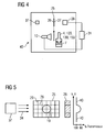
- Ebenso vorzugsweise kann aber auch die Referenzplatte 25 verfahren werden, also beispielsweise zwischen Beschichtungsmaterialquelle 10 und Bauteil 4 verfahren und beschichtet werden (
Figur 4 ) .
Dann wird sie 25 vorzugsweise zurückgefahren und vorzugsweise in einer anderen Position untersucht. - Die Vorder- 26 oder Rückseite 27 der Referenzplatte 25 kann von dem Sensor 28 untersucht werden.
- Danach wird der Spritzkegel 19 auf der Referenzplatte 25 innerhalb der Anlage 40 untersucht. Dies kann durch den Sensor 28, der vorzugsweise eine Reflektion misst, erfolgen. Dabei wird die Referenzplatte 25 in einem bevorzugten Ausführungsbeispiel von dem Sensor 28 beleuchtet und gleichzeitig die Reflektion erfasst.
- Ebenso vorzugsweise kann die Referenzplatte 25 mittels einer Belichtungsquelle 37 angestrahlt werden, wobei dann der Sensor 28 die Transmission der Belichtungsquelle 37 misst, so dass die Lage des Spritzkegels 19 bestimmt werden kann.
- Diese Informationen (siehe
Fig. 5 ) können vorzugsweise graphisch dargestellt und einem Operator der Vorrichtung 40 außerhalb der Vorrichtung 40 angezeigt werden. Der Operator kann die Informationen manuell auswerten.
Vorzugsweise kann eine Auswerteeinheit 31 vorhanden sein, die die Ergebnisse des Sensors 28 verarbeitet und vorzugsweise bewertet.
Die dabei gewonnenen Informationen werden vorzugsweise dazu benutzt, um die Beschichtungsmaterialquelle 10 neu zu justieren.
Dieser Schritt des Justierens kann jederzeit während des Beschichtungsverfahrens oder vor dem ersten Beschichten erfolgen.
Abweichungen des Spritzkegels 19 von der Sollgeometrie 22 können verursacht sein durch: - Dejustierung der Düse der Beschichtungsmaterialquelle 10
- Verschleiß der Düse der Beschichtungsmaterialquelle 10
- Dejustierung des Bauteils 4, 120, 130, 155.
- Die Auswertungsmethode der beschichteten Referenzplatte 25 wird anhand der
Figur 5 erläutert. - In
Figur 5 ist die Referenzplatte 25 mit einem Spritzkegel 19 dargestellt.
Die Belichtungsquelle 37 sendet Strahlen 34 aus, die im Bereich des Spritzkegels 19 nicht oder nur geschwächt zu dem Sensor 28 hinter der Referenzplatte 26 gelangen können. Dabei wird dann der Prozentanteil der Transmission 40 gemessen, wie es auf der rechten Seite derFigur 5 dargestellt ist. -
Figur 5 zeigt nur einen Schnitt der dreidimensionalen Geometrie (x, y-Transmission) des Spritzkegels 19. Zur Auswertung werden jedoch vorzugsweise die dreidimensionalen Ergebnisse verwendet. - Mittels Gitterhilfslinien 29 auf der Referenzplatte 25 kann eine Dejustierung der Materialquelle 10 überprüft werden.
- Die Vorrichtung 40 und das Verfahren haben den Vorteil, dass die Ergebnisse der Justierung automatisch ausgewertet werden können und sogar in digitalisierter Form gespeichert und archiviert werden können. Ebenfalls ist eine Korrektur der Plasmaparameter oder der Plasmadüse mittels einer Wissensdatenbank möglich.
Das Beschichtungsverfahren kann abgebrochen werden, wenn eine Dejustierung vorliegt bzw. es ist eine On-Time-Prozesskontrolle möglich. - Die
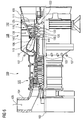
Figur 6 zeigt beispielhaft eine Gasturbine 100 in einem Längsteilschnitt.
Die Gasturbine 100 weist im Inneren einen um eine Rotationsachse 102 drehgelagerten Rotor 103 mit einer Welle 101 auf, der auch als Turbinenläufer bezeichnet wird.
Entlang des Rotors 103 folgen aufeinander ein Ansauggehäuse 104, ein Verdichter 105, eine beispielsweise torusartige Brennkammer 110, insbesondere Ringbrennkammer, mit mehreren koaxial angeordneten Brennern 107, eine Turbine 108 und das Abgasgehäuse 109.
Die Ringbrennkammer 110 kommuniziert mit einem beispielsweise ringförmigen Heißgaskanal 111. Dort bilden beispielsweise vier hintereinander geschaltete Turbinenstufen 112 die Turbine 108.
Jede Turbinenstufe 112 ist beispielsweise aus zwei Schaufelringen gebildet. In Strömungsrichtung eines Arbeitsmediums 113 gesehen folgt im Heißgaskanal 111 einer Leitschaufelreihe 115 eine aus Laufschaufeln 120 gebildete Reihe 125. - Die Leitschaufeln 130 sind dabei an einem Innengehäuse 138 eines Stators 143 befestigt, wohingegen die Laufschaufeln 120 einer Reihe 125 beispielsweise mittels einer Turbinenscheibe 133 am Rotor 103 angebracht sind.
An dem Rotor 103 angekoppelt ist ein Generator oder eine Arbeitsmaschine (nicht dargestellt). - Während des Betriebes der Gasturbine 100 wird vom Verdichter 105 durch das Ansauggehäuse 104 Luft 135 angesaugt und verdichtet. Die am turbinenseitigen Ende des Verdichters 105 bereitgestellte verdichtete Luft wird zu den Brennern 107 geführt und dort mit einem Brennmittel vermischt. Das Gemisch wird dann unter Bildung des Arbeitsmediums 113 in der Brennkammer 110 verbrannt. Von dort aus strömt das Arbeitsmedium 113 entlang des Heißgaskanals 111 vorbei an den Leitschaufeln 130 und den Laufschaufeln 120. An den Laufschaufeln 120 entspannt sich das Arbeitsmedium 113 impulsübertragend, so dass die Laufschaufeln 120 den Rotor 103 antreiben und dieser die an ihn angekoppelte Arbeitsmaschine.
- Die dem heißen Arbeitsmedium 113 ausgesetzten Bauteile unterliegen während des Betriebes der Gasturbine 100 thermischen Belastungen. Die Leitschaufeln 130 und Laufschaufeln 120 der in Strömungsrichtung des Arbeitsmediums 113 gesehen ersten Turbinenstufe 112 werden neben den die Ringbrennkammer 110 auskleidenden Hitzeschildelementen am meisten thermisch belastet.
Um den dort herrschenden Temperaturen standzuhalten, können diese mittels eines Kühlmittels gekühlt werden.
Ebenso können Substrate der Bauteile eine gerichtete Struktur aufweisen, d.h. sie sind einkristallin (SX-Struktur) oder weisen nur längsgerichtete Körner auf (DS-Struktur).
Als Material für die Bauteile, insbesondere für die Turbinenschaufel 120, 130 und Bauteile der Brennkammer 110 werden beispielsweise eisen-, nickel- oder kobaltbasierte Superlegierungen verwendet. - Solche Superlegierungen sind beispielsweise aus der
EP 1 204 776 B1 ,EP 1 306 454 ,EP 1 319 729 A1 ,WO 99/67435 WO 00/44949 - Ebenso können die Schaufeln 120, 130 Beschichtungen gegen Korrosion (MCrAlX; M ist zumindest ein Element der Gruppe Eisen (Fe), Kobalt (Co), Nickel (Ni), X ist ein Aktivelement und steht für Yttrium (Y) und/oder Silizium, Scandium (Sc) und/oder zumindest ein Element der Seltenen Erden bzw. Hafnium). Solche Legierungen sind bekannt aus der
EP 0 486 489 B1 ,EP 0 786 017 B1 ,EP 0 412 397 B1 oderEP 1 306 454 A1 . - Auf der MCrAlX kann noch eine Wärmedämmschicht vorhanden sein, und besteht beispielsweise aus ZrO2, Y2O3-ZrO2, d.h. sie ist nicht, teilweise oder vollständig stabilisiert durch Yttriumoxid und/oder Kalziumoxid und/oder Magnesiumoxid.
Durch geeignete Beschichtungsverfahren wie z.B. Elektronenstrahlverdampfen (EB-PVD) werden stängelförmige Körner in der Wärmedämmschicht erzeugt. - Die Leitschaufel 130 weist einen dem Innengehäuse 138 der Turbine 108 zugewandten Leitschaufelfuß (hier nicht dargestellt) und einen dem Leitschaufelfuß gegenüberliegenden Leitschaufelkopf auf. Der Leitschaufelkopf ist dem Rotor 103 zugewandt und an einem Befestigungsring 140 des Stators 143 festgelegt.
- Die
Figur 7 zeigt in perspektivischer Ansicht eine Laufschaufel 120 oder Leitschaufel 130 einer Strömungsmaschine, die sich entlang einer Längsachse 121 erstreckt. - Die Strömungsmaschine kann eine Gasturbine eines Flugzeugs oder eines Kraftwerks zur Elektrizitätserzeugung, eine Dampfturbine oder ein Kompressor sein.
- Die Schaufel 120, 130 weist entlang der Längsachse 121 aufeinander folgend einen Befestigungsbereich 400, eine daran angrenzende Schaufelplattform 403 sowie ein Schaufelblatt 406 und eine Schaufelspitze 415 auf.
Als Leitschaufel 130 kann die Schaufel 130 an ihrer Schaufelspitze 415 eine weitere Plattform aufweisen (nicht dargestellt). - Im Befestigungsbereich 400 ist ein Schaufelfuß 183 gebildet, der zur Befestigung der Laufschaufeln 120, 130 an einer Welle oder einer Scheibe dient (nicht dargestellt).
Der Schaufelfuß 183 ist beispielsweise als Hammerkopf ausgestaltet. Andere Ausgestaltungen als Tannenbaum- oder Schwalbenschwanzfuß sind möglich.
Die Schaufel 120, 130 weist für ein Medium, das an dem Schaufelblatt 406 vorbeiströmt, eine Anströmkante 409 und eine Abströmkante 412 auf. - Bei herkömmlichen Schaufeln 120, 130 werden in allen Bereichen 400, 403, 406 der Schaufel 120, 130 beispielsweise massive metallische Werkstoffe, insbesondere Superlegierungen verwendet.
Solche Superlegierungen sind beispielsweise aus derEP 1 204 776 B1 ,EP 1 306 454 ,EP 1 319 729 A1 ,WO 99/67435 WO 00/44949
Die Schaufel 120, 130 kann hierbei durch ein Gussverfahren, auch mittels gerichteter Erstarrung, durch ein Schmiedeverfahren, durch ein Fräsverfahren oder Kombinationen daraus gefertigt sein. - Werkstücke mit einkristalliner Struktur oder Strukturen werden als Bauteile für Maschinen eingesetzt, die im Betrieb hohen mechanischen, thermischen und/oder chemischen Belastungen ausgesetzt sind.
Die Fertigung von derartigen einkristallinen Werkstücken erfolgt z.B. durch gerichtetes Erstarren aus der Schmelze. Es handelt sich dabei um Gießverfahren, bei denen die flüssige metallische Legierung zur einkristallinen Struktur, d.h. zum einkristallinen Werkstück, oder gerichtet erstarrt. - Dabei werden dendritische Kristalle entlang dem Wärmefluss ausgerichtet und bilden entweder eine stängelkristalline Kornstruktur (kolumnar, d.h. Körner, die über die ganze Länge des Werkstückes verlaufen und hier, dem allgemeinen Sprachgebrauch nach, als gerichtet erstarrt bezeichnet werden) oder eine einkristalline Struktur, d.h. das ganze Werkstück besteht aus einem einzigen Kristall. In diesen Verfahren muss man den Übergang zur globulitischen (polykristallinen) Erstarrung meiden, da sich durch ungerichtetes Wachstum notwendigerweise transversale und longitudinale Korngrenzen ausbilden, welche die guten Eigenschaften des gerichtet erstarrten oder einkristallinen Bauteiles zunichte machen.
Ist allgemein von gerichtet erstarrten Gefügen die Rede, so sind damit sowohl Einkristalle gemeint, die keine Korngrenzen oder höchstens Kleinwinkelkorngrenzen aufweisen, als auch Stängelkristallstrukturen, die wohl in longitudinaler Richtung verlaufende Korngrenzen, aber keine transversalen Korngrenzen aufweisen. Bei diesen zweitgenannten kristallinen Strukturen spricht man auch von gerichtet erstarrten Gefügen (directionally solidified structures).
Solche Verfahren sind aus derUS-PS 6,024,792 und derEP 0 892 090 A1 bekannt. - Ebenso können die Schaufeln 120, 130 Beschichtungen gegen Korrosion oder Oxidation aufweisen, z. B. (MCrAlX; M ist zumindest ein Element der Gruppe Eisen (Fe), Kobalt (Co), Nickel (Ni), X ist ein Aktivelement und steht für Yttrium (Y) und/oder Silizium und/oder zumindest ein Element der Seltenen Erden, bzw. Hafnium (Hf)). Solche Legierungen sind bekannt aus der
EP 0 486 489 B1 ,EP 0 786 017 B1 ,EP 0 412 397 B1 oderEP 1 306 454 A1 , die bzgl. der chemischen Zusammensetzung der Legierung Teil dieser Offenbarung sein sollen.
Die Dichte liegt vorzugsweise bei 95% der theoretischen Dichte.
Auf der MCrAlX-Schicht (als Zwischenschicht oder als äußerste Schicht) bildet sich eine schützende Aluminiumoxidschicht (TGO = thermal grown oxide layer). - Vorzugsweise weist die Schichtzusammensetzung Co-30Ni-28Cr-8Al-0,6Y-0,7Si oder Co-28Ni-24Cr-10Al-0,6Y auf. Neben diesen kobaltbasierten Schutzbeschichtungen werden auch vorzugsweise nickelbasierte Schutzschichten verwendet wie Ni-10Cr-12Al-0,6Y-3Re oder Ni-12Co-21Cr-11Al-0,4Y-2Re oder Ni-25Co-17Cr-10Al-0,4Y-1,5Re.
- Auf der MCrAlX kann noch eine Wärmedämmschicht vorhanden sein, die vorzugsweise die äußerste Schicht ist, und besteht beispielsweise aus ZrO2, Y2O3-ZrO2, d.h. sie ist nicht, teilweise oder vollständig stabilisiert durch Yttriumoxid und/oder Kalziumoxid und/oder Magnesiumoxid.
Die Wärmedämmschicht bedeckt die gesamte MCrAlX-Schicht. Durch geeignete Beschichtungsverfahren wie z.B. Elektronenstrahlverdampfen (EB-PVD) werden stängelförmige Körner in der Wärmedämmschicht erzeugt.
Andere Beschichtungsverfahren sind denkbar, z.B. atmosphärisches Plasmaspritzen (APS), LPPS, VPS oder CVD. Die Wärmedämmschicht kann poröse, mikro- oder makrorissbehaftete Körner zur besseren Thermoschockbeständigkeit aufweisen. Die Wärmedämmschicht ist also vorzugsweise poröser als die MCrAlX-Schicht. - Wiederaufarbeitung (Refurbishment) bedeutet, dass Bauteile 120, 130 nach ihrem Einsatz gegebenenfalls von Schutzschichten befreit werden müssen (z.B. durch Sandstrahlen). Danach erfolgt eine Entfernung der Korrosions- und/oder Oxidationsschichten bzw. -produkte. Gegebenenfalls werden auch noch Risse im Bauteil 120, 130 repariert. Danach erfolgt eine Wiederbeschichtung des Bauteils 120, 130 und ein erneuter Einsatz des Bauteils 120, 130.
- Die Schaufel 120, 130 kann hohl oder massiv ausgeführt sein. Wenn die Schaufel 120, 130 gekühlt werden soll, ist sie hohl und weist ggf. noch Filmkühllöcher 418 (gestrichelt angedeutet) auf.
- Die
Figur 8 zeigt eine Brennkammer 110 einer Gasturbine.
Die Brennkammer 110 ist beispielsweise als so genannte Ringbrennkammer ausgestaltet, bei der eine Vielzahl von in Umfangsrichtung um eine Rotationsachse 102 herum angeordneten Brennern 107 in einen gemeinsamen Brennkammerraum 154 münden, die Flammen 156 erzeugen. Dazu ist die Brennkammer 110 in ihrer Gesamtheit als ringförmige Struktur ausgestaltet, die um die Rotationsachse 102 herum positioniert ist. - Zur Erzielung eines vergleichsweise hohen Wirkungsgrades ist die Brennkammer 110 für eine vergleichsweise hohe Temperatur des Arbeitsmediums M von etwa 1000°C bis 1600°C ausgelegt. Um auch bei diesen, für die Materialien ungünstigen Betriebsparametern eine vergleichsweise lange Betriebsdauer zu ermöglichen, ist die Brennkammerwand 153 auf ihrer dem Arbeitsmedium M zugewandten Seite mit einer aus Hitzeschildelementen 155 gebildeten Innenauskleidung versehen.
Jedes Hitzeschildelement 155 aus einer Legierung ist arbeitsmediumsseitig mit einer besonders hitzebeständigen Schutzschicht (MCrAlX-Schicht und/oder keramische Beschichtung) ausgestattet oder ist aus hochtemperaturbeständigem Material (massive keramische Steine) gefertigt.
Diese Schutzschichten können ähnlich der Turbinenschaufeln sein, also bedeutet beispielsweise MCrAlX: M ist zumindest ein Element der Gruppe Eisen (Fe), Kobalt (Co), Nickel (Ni), X ist ein Aktivelement und steht für Yttrium (Y) und/oder Silizium und/oder zumindest ein Element der Seltenen Erden, bzw. Hafnium (Hf). Solche Legierungen sind bekannt aus derEP 0 486 489 B1 ,EP 0 786 017 B1 ,EP 0 412 397 B1 oderEP 1 306 454 A1 . - Auf der MCrAlX kann noch eine beispielsweise keramische Wärmedämmschicht vorhanden sein und besteht beispielsweise aus ZrO2, Y2O3-ZrO2, d.h. sie ist nicht, teilweise oder vollständig stabilisiert durch Yttriumoxid und/oder Kalziumoxid und/oder Magnesiumoxid.
- Durch geeignete Beschichtungsverfahren wie z.B. Elektronenstrahlverdampfen (EB-PVD) werden stängelförmige Körner in der Wärmedämmschicht erzeugt.
Andere Beschichtungsverfahren sind denkbar, z.B. atmosphärisches Plasmaspritzen (APS, LPPS, VPS) oder CVD. Die Wärmedämmschicht kann poröse, mikro- oder makrorissbehaftete Körner zur besseren Thermoschockbeständigkeit aufweisen. - Wiederaufarbeitung (Refurbishment) bedeutet, dass Hitzeschildelemente 155 nach ihrem Einsatz gegebenenfalls von Schutzschichten befreit werden müssen (z.B. durch Sandstrahlen). Danach erfolgt eine Entfernung der Korrosions- und/oder Oxidationsschichten bzw. -produkte. Gegebenenfalls werden auch noch Risse in dem Hitzeschildelement 155 repariert. Danach erfolgt eine Wiederbeschichtung der Hitzeschildelemente 155 und ein erneuter Einsatz der Hitzeschildelemente 155.
- Aufgrund der hohen Temperaturen im Inneren der Brennkammer 110 kann zudem für die Hitzeschildelemente 155 bzw. für deren Halteelemente ein Kühlsystem vorgesehen sein. Die Hitzeschildelemente 155 sind dann beispielsweise hohl und weisen ggf. noch in den Brennkammerraum 154 mündende Kühllöcher (nicht dargestellt) auf.
Claims (22)
- Beschichtungsvorrichtung (40) mit einer Beschichtungsmaterialquelle (10),
in der (40) ein zu beschichtendes Bauteil (4, 120, 130, 155) eingebaut werden kann,
und beschichtet werden kann,
dadurch gekennzeichnet, dass
die Beschichtungsvorrichtung (40) aufweist:das zu beschichtende Bauteil (4)
eine durch die Beschichtungsmaterialquelle (10) beschichtbare und von dem Bauteil (4) separate Referenzplatte (25),die (25) innerhalb der Beschichtungsvorrichtung (40) untersuchbar ist undeinen Sensor (28) zur Untersuchung der Referenzplatte (25). - Vorrichtung nach Anspruch 1,
die eine optisch transparente Referenzplatte (25) aufweist. - Vorrichtung nach Anspruch 1 oder 2,
in der eine Beleuchtungsquelle (37) vorhanden ist, die (37) die Referenzplatte (25) beleuchten kann, insbesondere eine beschichtete Seite (27) der Referenzplatte (25). - Vorrichtung nach Anspruch 1, 2 oder 3,
bei der die Referenzplatte (25) während eines Beschichtungsvorgangs austauschbar ist. - Vorrichtung nach Anspruch 1, 2, 3 oder 4,
die eine Auswerteeinheit (31) aufweist,
die (31) die Daten des Sensors (28) verarbeitet. - Vorrichtung nach Anspruch 1, 2, 3, 4 oder 5,
bei der die Beschichtungsmaterialquelle (10) zur Referenzplatte (25) verfahrbar ist. - Vorrichtung nach Anspruch 1, 2, 3, 4 oder 5,
bei der die Referenzplatte (25) zur Beschichtungsmaterialquelle (10) hin verfahrbar ist. - Verfahren zum Beschichten eines Bauteils (4, 120, 130, 155) mittels einer der Beschichtungsmaterialquelle (10), bei dem das Bauteil (4, 120, 130, 155) beschichtet wird, und bei dem eine von dem Bauteil (4) verschiedene Referenzplatte (25) durch die Beschichtungsmaterialquelle (10) beschichtet wird und
wobei das Beschichtungsergebnis auf der Referenzplatte (25) innerhalb der Beschichtungsvorrichtung (40) mittels eines Sensors (28) in der Beschichtungsvorrichtung (40),
untersucht wird. - Verfahren nach Anspruch 8,
bei dem eine Auswerteeinheit (31) die Daten des Sensors (28) verarbeitet. - Verfahren nach Anspruch 8,
bei dem eine optisch untersuchbare Referenzplatte (25) verwendet wird. - Verfahren nach Anspruch 8, 9 oder 10,
bei dem eine optisch transparente Referenzplatte (25) verwendet wird. - Verfahren nach Anspruch 8, 9, 10 oder 11,
bei dem eine nicht beschichtete Seite (27) der Referenzplatte (25) von dem Sensor (28) untersucht wird. - Verfahren nach Anspruch 8, 9, 10 oder 11,
bei dem eine beschichtete Seite (26) der Referenzplatte (25) von dem Sensor (28) untersucht wird. - Verfahren nach Anspruch 8, 9, 10, 11, 12 oder 13,
bei dem die Bewertung der Referenzplatte (25) zur Justierung der Beschichtungsmaterialquelle (10) verwendet wird. - Verfahren nach Anspruch 8, 9, 10, 11, 12, 13 oder 14, bei dem die Bewertung der Referenzplatte (25) zur Auswechslung der Beschichtungsmaterialquelle (10) führt.
- Verfahren nach Anspruch 8, 10, 11, 12, 13, 14 oder 15, bei dem die Beschichtung der Referenzplatte (25) vor dem ersten Beschichten des Bauteils (4, 120, 130, 155) erfolgt.
- Verfahren nach Anspruch 8, 10, 11, 12, 13, 14, 15 oder 16,
bei dem die Beschichtung der Referenzplatte (25) während der Beschichtung des Bauteils (4, 120, 130, 155) erfolgt. - Verfahren nach einem oder mehreren der Ansprüche 8 oder 10 bis 17,
bei dem die Beschichtung der Referenzplatte (25) nach der kompletten Beschichtung des Bauteils (4, 120, 130, 155) erfolgt. - Verfahren nach einem oder mehreren der Ansprüche 8, 10 bis 18,
bei dem die Beschichtungsmaterialquelle (10) zur Referenzplatte (25) verfahren wird,
um die Referenzplatte (25) zu beschichten. - Verfahren nach einem oder mehreren der Ansprüche 8, 10 bis 18,
bei dem die Referenzplatte (25) zur Beschichtungsmaterialquelle (10) verfahren wird,
um die Referenzplatte (25) zu beschichten. - Verfahren nach einem oder mehreren der Ansprüche 8, 10 bis 20,
das beim Plasmaspritzen, HVOF Beschichten oder Kaltgasspritzen verwendet wird. - Verfahren nach einem oder mehreren der Ansprüche 8, 10 bis 20,
das beim PVD- oder CVD-Verfahren verwendet wird.
Priority Applications (5)
| Application Number | Priority Date | Filing Date | Title |
|---|---|---|---|
| AT07006095T ATE468734T1 (de) | 2007-03-23 | 2007-03-23 | Vorrichtung und verfahren zum beschichten eines bauteils mit justiereinrichtung |
| DE502007003848T DE502007003848D1 (de) | 2007-03-23 | 2007-03-23 | Vorrichtung und Verfahren zum Beschichten eines Bauteils mit Justiereinrichtung |
| EP07006095A EP1978790B1 (de) | 2007-03-23 | 2007-03-23 | Vorrichtung und Verfahren zum Beschichten eines Bauteils mit Justiereinrichtung |
| ES07006095T ES2344228T3 (es) | 2007-03-23 | 2007-03-23 | Dispositivo y procedimiento para revestir un componente con dispositivo de ajuste. |
| US12/077,613 US8689731B2 (en) | 2007-03-23 | 2008-03-20 | Apparatus and process for coating a component with aligning device |
Applications Claiming Priority (1)
| Application Number | Priority Date | Filing Date | Title |
|---|---|---|---|
| EP07006095A EP1978790B1 (de) | 2007-03-23 | 2007-03-23 | Vorrichtung und Verfahren zum Beschichten eines Bauteils mit Justiereinrichtung |
Publications (2)
| Publication Number | Publication Date |
|---|---|
| EP1978790A1 EP1978790A1 (de) | 2008-10-08 |
| EP1978790B1 true EP1978790B1 (de) | 2010-05-19 |
Family
ID=38226447
Family Applications (1)
| Application Number | Title | Priority Date | Filing Date |
|---|---|---|---|
| EP07006095A Not-in-force EP1978790B1 (de) | 2007-03-23 | 2007-03-23 | Vorrichtung und Verfahren zum Beschichten eines Bauteils mit Justiereinrichtung |
Country Status (5)
| Country | Link |
|---|---|
| US (1) | US8689731B2 (de) |
| EP (1) | EP1978790B1 (de) |
| AT (1) | ATE468734T1 (de) |
| DE (1) | DE502007003848D1 (de) |
| ES (1) | ES2344228T3 (de) |
Families Citing this family (2)
| Publication number | Priority date | Publication date | Assignee | Title |
|---|---|---|---|---|
| KR101026935B1 (ko) * | 2003-12-10 | 2011-04-04 | 엘지디스플레이 주식회사 | 디스펜서 정렬장치 및 그 방법 |
| DE102009036407A1 (de) | 2009-08-06 | 2011-02-10 | Mtu Aero Engines Gmbh | Abreibbarer Schaufelspitzenbelag |
Family Cites Families (17)
| Publication number | Priority date | Publication date | Assignee | Title |
|---|---|---|---|---|
| US3454414A (en) * | 1964-11-02 | 1969-07-08 | Sperry Rand Corp | Photochromic material |
| US4334495A (en) * | 1978-07-11 | 1982-06-15 | Trw Inc. | Method and apparatus for use in making an object |
| DE58908611D1 (de) | 1989-08-10 | 1994-12-08 | Siemens Ag | Hochtemperaturfeste korrosionsschutzbeschichtung, insbesondere für gasturbinenbauteile. |
| DE3926479A1 (de) | 1989-08-10 | 1991-02-14 | Siemens Ag | Rheniumhaltige schutzbeschichtung, mit grosser korrosions- und/oder oxidationsbestaendigkeit |
| US5047612A (en) * | 1990-02-05 | 1991-09-10 | General Electric Company | Apparatus and method for controlling powder deposition in a plasma spray process |
| CA2055267C (en) * | 1991-11-12 | 1999-01-12 | Christian Moreau | Method and apparatus for monitoring the temperature and velocity of plasma sprayed particles |
| WO1996012049A1 (de) | 1994-10-14 | 1996-04-25 | Siemens Aktiengesellschaft | Schutzschicht zum schutz eines bauteils gegen korrosion, oxidation und thermische überbeanspruchung sowie verfahren zu ihrer herstellung |
| EP0892090B1 (de) | 1997-02-24 | 2008-04-23 | Sulzer Innotec Ag | Verfahren zum Herstellen von einkristallinen Strukturen |
| EP0861927A1 (de) | 1997-02-24 | 1998-09-02 | Sulzer Innotec Ag | Verfahren zum Herstellen von einkristallinen Strukturen |
| EP1306454B1 (de) | 2001-10-24 | 2004-10-06 | Siemens Aktiengesellschaft | Rhenium enthaltende Schutzschicht zum Schutz eines Bauteils gegen Korrosion und Oxidation bei hohen Temperaturen |
| WO1999067435A1 (en) | 1998-06-23 | 1999-12-29 | Siemens Aktiengesellschaft | Directionally solidified casting with improved transverse stress rupture strength |
| US6231692B1 (en) | 1999-01-28 | 2001-05-15 | Howmet Research Corporation | Nickel base superalloy with improved machinability and method of making thereof |
| DE50006694D1 (de) | 1999-07-29 | 2004-07-08 | Siemens Ag | Hochtemperaturbeständiges bauteil und verfahren zur herstellung des hochtemperaturbeständigen bauteils |
| DE50112339D1 (de) | 2001-12-13 | 2007-05-24 | Siemens Ag | Hochtemperaturbeständiges Bauteil aus einkristalliner oder polykristalliner Nickel-Basis-Superlegierung |
| DE10203884A1 (de) * | 2002-01-31 | 2003-08-14 | Flumesys Gmbh Fluidmes Und Sys | Vorrichtung und Verfahren zum thermischen Spritzen |
| EP1548448A4 (de) * | 2002-09-27 | 2009-11-11 | Shimadzu Corp | Fl ssigkeitsportionierungsverfahren und -einrichtung |
| KR101026935B1 (ko) * | 2003-12-10 | 2011-04-04 | 엘지디스플레이 주식회사 | 디스펜서 정렬장치 및 그 방법 |
-
2007
- 2007-03-23 DE DE502007003848T patent/DE502007003848D1/de active Active
- 2007-03-23 ES ES07006095T patent/ES2344228T3/es active Active
- 2007-03-23 AT AT07006095T patent/ATE468734T1/de active
- 2007-03-23 EP EP07006095A patent/EP1978790B1/de not_active Not-in-force
-
2008
- 2008-03-20 US US12/077,613 patent/US8689731B2/en not_active Expired - Fee Related
Also Published As
| Publication number | Publication date |
|---|---|
| ATE468734T1 (de) | 2010-06-15 |
| US20080286443A1 (en) | 2008-11-20 |
| ES2344228T3 (es) | 2010-08-20 |
| US8689731B2 (en) | 2014-04-08 |
| DE502007003848D1 (de) | 2010-07-01 |
| EP1978790A1 (de) | 2008-10-08 |
Similar Documents
| Publication | Publication Date | Title |
|---|---|---|
| EP1952931A1 (de) | Mechtrode mit Pulverzufuhr und Verfahren zur Benutzung dieser Mechtrode | |
| DE102008018264A1 (de) | Schweißverfahren mit geregeltem Temperaturverlauf und eine Vorrichtung dafür | |
| EP2314987A1 (de) | Oberflächenanalyse zur Detektierung verschlossener Löcher und Vorrichtung | |
| EP2589925A1 (de) | 3D-Oberflächeninspektionssystem mittels 2D-Aufnahmen und Verfahren | |
| DE102013223688A1 (de) | Verfahren und Vorrichtung zum automatisierten Aufbringen einer Spritzbeschichtung | |
| EP2450465A1 (de) | Poröses Schichtsystem mit poröserer Innenschicht | |
| EP2312267A1 (de) | Verfahren zur Schichtdickenmessung mittels Lasertriangulation und Vorrichtung | |
| EP2386823A1 (de) | Oberflächenanalyse zur Detektierung verschlossener Löcher und Verfahren zur Wiedereröffnung | |
| EP2186594A1 (de) | Verfahren und Vorrichtung zur Vorwärmung beim Schweißen unter Verwendung eines zweiten Laserstrahles | |
| EP2373824B1 (de) | Verfahren zum beschichten eines bauteils mit filmkühllöchern, und bauteil | |
| DE102008019636A1 (de) | Bauteil mit Schweißnaht und Verfahren zur Herstellung einer Schweißnaht | |
| DE102008016170A1 (de) | Bauteil mit sich überlappenden Schweißnähten und ein Verfahren zur Herstellung | |
| EP2062672A1 (de) | Verfahren zum Löten weiter Spalte | |
| EP2353725A1 (de) | Spritzdüse und Verfahren zum atmosphärischen Spritzen, Vorrichtung zum Beschichten und beschichtetes Bauteil | |
| EP2241397A1 (de) | Belotung von Löchern, Verfahren zum Beschichten und Lötgutstäbchen | |
| EP2224039A1 (de) | Beschichtung mit thermischen und nicht-thermischen Beschichtungsverfahren | |
| EP2365106A1 (de) | Keramische Wärmedämmschichtsystem mit modifizierter Anbindungsschicht | |
| EP2226149A1 (de) | Zweischritt-Schweissverfahren | |
| EP2584067A1 (de) | Bauteil mit Graphen und Verfahren zur Herstellung von Bauteilen mit Graphen | |
| EP2312122A1 (de) | Referenzbestimmung zur Ermittlung der Lage von verschlossenen Löchern, Vorrichtung und Bearbeitungsvorrichtung | |
| WO2009106375A1 (de) | Vorrichtung zur strahlsteuerung und ein verfahren zur strahlsteuerung | |
| DE102014220180A1 (de) | Überwachung und Steuerung eines Beschichtungsvorgangs anhand einer Wärmeverteilung auf dem Werkstück | |
| EP2386824A1 (de) | Oberflächenanalyse zur Detektierung veschlossener Löcher und Verfahren zur Wiederöffnung | |
| EP2053145A1 (de) | Verfahren zur Entfernung einer metallischen Schicht mittels FIC in einem Zwischenschritt | |
| EP1978790A1 (de) | Vorrichtung und Verfahren zum Beschichten eines Bauteils mit Justiereinrichtung |
Legal Events
| Date | Code | Title | Description |
|---|---|---|---|
| PUAI | Public reference made under article 153(3) epc to a published international application that has entered the european phase |
Free format text: ORIGINAL CODE: 0009012 |
|
| 17P | Request for examination filed |
Effective date: 20070919 |
|
| AK | Designated contracting states |
Kind code of ref document: A1 Designated state(s): AT BE BG CH CY CZ DE DK EE ES FI FR GB GR HU IE IS IT LI LT LU LV MC MT NL PL PT RO SE SI SK TR |
|
| AX | Request for extension of the european patent |
Extension state: AL BA HR MK RS |
|
| AKX | Designation fees paid |
Designated state(s): AT BE BG CH CY CZ DE DK EE ES FI FR GB GR HU IE IS IT LI LT LU LV MC MT NL PL PT RO SE SI SK TR |
|
| GRAP | Despatch of communication of intention to grant a patent |
Free format text: ORIGINAL CODE: EPIDOSNIGR1 |
|
| GRAS | Grant fee paid |
Free format text: ORIGINAL CODE: EPIDOSNIGR3 |
|
| GRAA | (expected) grant |
Free format text: ORIGINAL CODE: 0009210 |
|
| AK | Designated contracting states |
Kind code of ref document: B1 Designated state(s): AT BE BG CH CY CZ DE DK EE ES FI FR GB GR HU IE IS IT LI LT LU LV MC MT NL PL PT RO SE SI SK TR |
|
| REG | Reference to a national code |
Ref country code: GB Ref legal event code: FG4D Free format text: NOT ENGLISH |
|
| REG | Reference to a national code |
Ref country code: CH Ref legal event code: NV Representative=s name: SIEMENS SCHWEIZ AG Ref country code: CH Ref legal event code: EP |
|
| REG | Reference to a national code |
Ref country code: IE Ref legal event code: FG4D Free format text: LANGUAGE OF EP DOCUMENT: GERMAN |
|
| REF | Corresponds to: |
Ref document number: 502007003848 Country of ref document: DE Date of ref document: 20100701 Kind code of ref document: P |
|
| REG | Reference to a national code |
Ref country code: ES Ref legal event code: FG2A Ref document number: 2344228 Country of ref document: ES Kind code of ref document: T3 |
|
| REG | Reference to a national code |
Ref country code: NL Ref legal event code: T3 |
|
| LTIE | Lt: invalidation of european patent or patent extension |
Effective date: 20100519 |
|
| PG25 | Lapsed in a contracting state [announced via postgrant information from national office to epo] |
Ref country code: SE Free format text: LAPSE BECAUSE OF FAILURE TO SUBMIT A TRANSLATION OF THE DESCRIPTION OR TO PAY THE FEE WITHIN THE PRESCRIBED TIME-LIMIT Effective date: 20100519 Ref country code: LT Free format text: LAPSE BECAUSE OF FAILURE TO SUBMIT A TRANSLATION OF THE DESCRIPTION OR TO PAY THE FEE WITHIN THE PRESCRIBED TIME-LIMIT Effective date: 20100519 |
|
| PG25 | Lapsed in a contracting state [announced via postgrant information from national office to epo] |
Ref country code: LV Free format text: LAPSE BECAUSE OF FAILURE TO SUBMIT A TRANSLATION OF THE DESCRIPTION OR TO PAY THE FEE WITHIN THE PRESCRIBED TIME-LIMIT Effective date: 20100519 Ref country code: FI Free format text: LAPSE BECAUSE OF FAILURE TO SUBMIT A TRANSLATION OF THE DESCRIPTION OR TO PAY THE FEE WITHIN THE PRESCRIBED TIME-LIMIT Effective date: 20100519 Ref country code: IS Free format text: LAPSE BECAUSE OF FAILURE TO SUBMIT A TRANSLATION OF THE DESCRIPTION OR TO PAY THE FEE WITHIN THE PRESCRIBED TIME-LIMIT Effective date: 20100919 Ref country code: SI Free format text: LAPSE BECAUSE OF FAILURE TO SUBMIT A TRANSLATION OF THE DESCRIPTION OR TO PAY THE FEE WITHIN THE PRESCRIBED TIME-LIMIT Effective date: 20100519 |
|
| PG25 | Lapsed in a contracting state [announced via postgrant information from national office to epo] |
Ref country code: PL Free format text: LAPSE BECAUSE OF FAILURE TO SUBMIT A TRANSLATION OF THE DESCRIPTION OR TO PAY THE FEE WITHIN THE PRESCRIBED TIME-LIMIT Effective date: 20100519 Ref country code: CY Free format text: LAPSE BECAUSE OF FAILURE TO SUBMIT A TRANSLATION OF THE DESCRIPTION OR TO PAY THE FEE WITHIN THE PRESCRIBED TIME-LIMIT Effective date: 20100602 |
|
| REG | Reference to a national code |
Ref country code: IE Ref legal event code: FD4D |
|
| PG25 | Lapsed in a contracting state [announced via postgrant information from national office to epo] |
Ref country code: IE Free format text: LAPSE BECAUSE OF FAILURE TO SUBMIT A TRANSLATION OF THE DESCRIPTION OR TO PAY THE FEE WITHIN THE PRESCRIBED TIME-LIMIT Effective date: 20100519 Ref country code: GR Free format text: LAPSE BECAUSE OF FAILURE TO SUBMIT A TRANSLATION OF THE DESCRIPTION OR TO PAY THE FEE WITHIN THE PRESCRIBED TIME-LIMIT Effective date: 20100820 Ref country code: DK Free format text: LAPSE BECAUSE OF FAILURE TO SUBMIT A TRANSLATION OF THE DESCRIPTION OR TO PAY THE FEE WITHIN THE PRESCRIBED TIME-LIMIT Effective date: 20100519 Ref country code: EE Free format text: LAPSE BECAUSE OF FAILURE TO SUBMIT A TRANSLATION OF THE DESCRIPTION OR TO PAY THE FEE WITHIN THE PRESCRIBED TIME-LIMIT Effective date: 20100519 |
|
| PG25 | Lapsed in a contracting state [announced via postgrant information from national office to epo] |
Ref country code: SK Free format text: LAPSE BECAUSE OF FAILURE TO SUBMIT A TRANSLATION OF THE DESCRIPTION OR TO PAY THE FEE WITHIN THE PRESCRIBED TIME-LIMIT Effective date: 20100519 Ref country code: RO Free format text: LAPSE BECAUSE OF FAILURE TO SUBMIT A TRANSLATION OF THE DESCRIPTION OR TO PAY THE FEE WITHIN THE PRESCRIBED TIME-LIMIT Effective date: 20100519 Ref country code: CZ Free format text: LAPSE BECAUSE OF FAILURE TO SUBMIT A TRANSLATION OF THE DESCRIPTION OR TO PAY THE FEE WITHIN THE PRESCRIBED TIME-LIMIT Effective date: 20100519 |
|
| PLBE | No opposition filed within time limit |
Free format text: ORIGINAL CODE: 0009261 |
|
| STAA | Information on the status of an ep patent application or granted ep patent |
Free format text: STATUS: NO OPPOSITION FILED WITHIN TIME LIMIT |
|
| 26N | No opposition filed |
Effective date: 20110222 |
|
| REG | Reference to a national code |
Ref country code: DE Ref legal event code: R097 Ref document number: 502007003848 Country of ref document: DE Effective date: 20110221 |
|
| BERE | Be: lapsed |
Owner name: SIEMENS A.G. Effective date: 20110331 |
|
| PG25 | Lapsed in a contracting state [announced via postgrant information from national office to epo] |
Ref country code: MC Free format text: LAPSE BECAUSE OF NON-PAYMENT OF DUE FEES Effective date: 20110331 |
|
| PG25 | Lapsed in a contracting state [announced via postgrant information from national office to epo] |
Ref country code: BE Free format text: LAPSE BECAUSE OF NON-PAYMENT OF DUE FEES Effective date: 20110331 Ref country code: MT Free format text: LAPSE BECAUSE OF FAILURE TO SUBMIT A TRANSLATION OF THE DESCRIPTION OR TO PAY THE FEE WITHIN THE PRESCRIBED TIME-LIMIT Effective date: 20100519 |
|
| PG25 | Lapsed in a contracting state [announced via postgrant information from national office to epo] |
Ref country code: DE Free format text: LAPSE BECAUSE OF NON-PAYMENT OF DUE FEES Effective date: 20111001 |
|
| REG | Reference to a national code |
Ref country code: AT Ref legal event code: MM01 Ref document number: 468734 Country of ref document: AT Kind code of ref document: T Effective date: 20120323 |
|
| PG25 | Lapsed in a contracting state [announced via postgrant information from national office to epo] |
Ref country code: LU Free format text: LAPSE BECAUSE OF NON-PAYMENT OF DUE FEES Effective date: 20110323 |
|
| PG25 | Lapsed in a contracting state [announced via postgrant information from national office to epo] |
Ref country code: PT Free format text: LAPSE BECAUSE OF NON-PAYMENT OF DUE FEES Effective date: 20100519 Ref country code: AT Free format text: LAPSE BECAUSE OF NON-PAYMENT OF DUE FEES Effective date: 20120323 |
|
| PG25 | Lapsed in a contracting state [announced via postgrant information from national office to epo] |
Ref country code: BG Free format text: LAPSE BECAUSE OF FAILURE TO SUBMIT A TRANSLATION OF THE DESCRIPTION OR TO PAY THE FEE WITHIN THE PRESCRIBED TIME-LIMIT Effective date: 20100819 Ref country code: TR Free format text: LAPSE BECAUSE OF FAILURE TO SUBMIT A TRANSLATION OF THE DESCRIPTION OR TO PAY THE FEE WITHIN THE PRESCRIBED TIME-LIMIT Effective date: 20100519 |
|
| PG25 | Lapsed in a contracting state [announced via postgrant information from national office to epo] |
Ref country code: HU Free format text: LAPSE BECAUSE OF FAILURE TO SUBMIT A TRANSLATION OF THE DESCRIPTION OR TO PAY THE FEE WITHIN THE PRESCRIBED TIME-LIMIT Effective date: 20100519 |
|
| REG | Reference to a national code |
Ref country code: FR Ref legal event code: PLFP Year of fee payment: 9 |
|
| PGFP | Annual fee paid to national office [announced via postgrant information from national office to epo] |
Ref country code: NL Payment date: 20150303 Year of fee payment: 9 Ref country code: IT Payment date: 20150328 Year of fee payment: 9 |
|
| PGFP | Annual fee paid to national office [announced via postgrant information from national office to epo] |
Ref country code: GB Payment date: 20150312 Year of fee payment: 9 Ref country code: FR Payment date: 20150311 Year of fee payment: 9 |
|
| PGFP | Annual fee paid to national office [announced via postgrant information from national office to epo] |
Ref country code: ES Payment date: 20150409 Year of fee payment: 9 Ref country code: CH Payment date: 20150602 Year of fee payment: 9 Ref country code: DE Payment date: 20150513 Year of fee payment: 9 |
|
| REG | Reference to a national code |
Ref country code: DE Ref legal event code: R119 Ref document number: 502007003848 Country of ref document: DE |
|
| REG | Reference to a national code |
Ref country code: CH Ref legal event code: PL |
|
| REG | Reference to a national code |
Ref country code: NL Ref legal event code: MM Effective date: 20160401 |
|
| GBPC | Gb: european patent ceased through non-payment of renewal fee |
Effective date: 20160323 |
|
| REG | Reference to a national code |
Ref country code: FR Ref legal event code: ST Effective date: 20161130 |
|
| PG25 | Lapsed in a contracting state [announced via postgrant information from national office to epo] |
Ref country code: LI Free format text: LAPSE BECAUSE OF NON-PAYMENT OF DUE FEES Effective date: 20160331 Ref country code: FR Free format text: LAPSE BECAUSE OF NON-PAYMENT OF DUE FEES Effective date: 20160331 Ref country code: NL Free format text: LAPSE BECAUSE OF NON-PAYMENT OF DUE FEES Effective date: 20160401 Ref country code: GB Free format text: LAPSE BECAUSE OF NON-PAYMENT OF DUE FEES Effective date: 20160323 Ref country code: CH Free format text: LAPSE BECAUSE OF NON-PAYMENT OF DUE FEES Effective date: 20160331 |
|
| PG25 | Lapsed in a contracting state [announced via postgrant information from national office to epo] |
Ref country code: IT Free format text: LAPSE BECAUSE OF NON-PAYMENT OF DUE FEES Effective date: 20160323 |
|
| PG25 | Lapsed in a contracting state [announced via postgrant information from national office to epo] |
Ref country code: ES Free format text: LAPSE BECAUSE OF NON-PAYMENT OF DUE FEES Effective date: 20160324 Ref country code: DE Free format text: LAPSE BECAUSE OF NON-PAYMENT OF DUE FEES Effective date: 20161001 |
|
| REG | Reference to a national code |
Ref country code: ES Ref legal event code: FD2A Effective date: 20181205 |