EP1978538B1 - Electrical switching apparatus and trip actuator reset assembly therefor - Google Patents
Electrical switching apparatus and trip actuator reset assembly therefor Download PDFInfo
- Publication number
- EP1978538B1 EP1978538B1 EP08006927.1A EP08006927A EP1978538B1 EP 1978538 B1 EP1978538 B1 EP 1978538B1 EP 08006927 A EP08006927 A EP 08006927A EP 1978538 B1 EP1978538 B1 EP 1978538B1
- Authority
- EP
- European Patent Office
- Prior art keywords
- reset
- trip
- trip actuator
- assembly
- cradle assembly
- Prior art date
- Legal status (The legal status is an assumption and is not a legal conclusion. Google has not performed a legal analysis and makes no representation as to the accuracy of the status listed.)
- Active
Links
Images


Classifications
-
- H—ELECTRICITY
- H01—ELECTRIC ELEMENTS
- H01H—ELECTRIC SWITCHES; RELAYS; SELECTORS; EMERGENCY PROTECTIVE DEVICES
- H01H3/00—Mechanisms for operating contacts
- H01H3/22—Power arrangements internal to the switch for operating the driving mechanism
- H01H3/30—Power arrangements internal to the switch for operating the driving mechanism using spring motor
-
- H—ELECTRICITY
- H01—ELECTRIC ELEMENTS
- H01H—ELECTRIC SWITCHES; RELAYS; SELECTORS; EMERGENCY PROTECTIVE DEVICES
- H01H71/00—Details of the protective switches or relays covered by groups H01H73/00 - H01H83/00
- H01H71/10—Operating or release mechanisms
- H01H71/12—Automatic release mechanisms with or without manual release
- H01H71/24—Electromagnetic mechanisms
-
- H—ELECTRICITY
- H01—ELECTRIC ELEMENTS
- H01H—ELECTRIC SWITCHES; RELAYS; SELECTORS; EMERGENCY PROTECTIVE DEVICES
- H01H71/00—Details of the protective switches or relays covered by groups H01H73/00 - H01H83/00
- H01H71/10—Operating or release mechanisms
- H01H71/50—Manual reset mechanisms which may be also used for manual release
- H01H71/52—Manual reset mechanisms which may be also used for manual release actuated by lever
- H01H71/522—Manual reset mechanisms which may be also used for manual release actuated by lever comprising a cradle-mechanism
-
- H—ELECTRICITY
- H01—ELECTRIC ELEMENTS
- H01H—ELECTRIC SWITCHES; RELAYS; SELECTORS; EMERGENCY PROTECTIVE DEVICES
- H01H3/00—Mechanisms for operating contacts
- H01H3/22—Power arrangements internal to the switch for operating the driving mechanism
- H01H3/30—Power arrangements internal to the switch for operating the driving mechanism using spring motor
- H01H2003/3068—Housing support frame for energy accumulator and cooperating mechanism
Definitions
- the invention relates generally to electrical switching apparatus and, more particularly, to trip actuator assemblies for electrical switching apparatus, such as circuit breakers.
- the invention also relates to reset assemblies for circuit breaker trip actuator assemblies.
- circuit breakers provide protection for electrical systems from electrical fault conditions such as, for example, current overloads, short circuits, abnormal voltage and other fault conditions.
- circuit breakers include an operating mechanism which opens electrical contact assemblies to interrupt the flow of current through the conductors of an electrical system in response to such fault conditions as detected, for example, by a trip unit.
- the operating mechanisms of some low-voltage circuit breakers typically include a pole shaft and a trip actuator assembly.
- the pole shaft pivots during opening and closing operations of the circuit breaker, which operations respectively correspond to electrical contact assemblies being opened (e.g., contacts separated) and closed (e.g., contacts electrically connected).
- the trip actuator assembly typically includes a trip bar, a trip actuator such as, for example, a solenoid, and a cradle assembly.
- the cradle assembly is coupled to and is cooperable with the pole shaft.
- the trip actuator e.g., solenoid
- the trip actuator has a spring, a coil which is energized by the trip unit in response to the electrical fault condition, and an actuating element such as, for example, a plunger.
- the plunger Normally (e.g., in the absence of the electrical fault condition), the plunger is latched (e.g., by a magnet) in a retracted position.
- the coil When the coil is energized, in response to the electrical fault condition, the magnetic force that holds the plunger in the retracted position is overcome and the spring biases the plunger to an extended position and maintains it there.
- the plunger When the plunger extends, it causes the trip bar to pivot and trip open the electrical contact assemblies.
- both the electrical contact assemblies and the trip actuator must be reset.
- the trip actuator assembly operates in conjunction with the pole shaft to perform the resetting operation. Specifically, when the circuit breaker operating mechanism is reset, the pole shaft pivots, thereby moving the cradle assembly. The cradle assembly then pivots a reset arm which, in turn, depresses the actuating element (e.g., plunger) and resets the trip actuator (e.g., solenoid).
- the actuating element e.g., plunger
- the trip actuator e.g., solenoid
- the travel and actuating force of the plunger are relatively limited. Therefore, to ensure that the trip actuator assembly consistently performs properly, the trip actuator assembly must be well designed, and the trip actuator of this assembly must be accurately installed and maintained in a precise predetermined position within the circuit breaker.
- trip actuator assemblies suffer from a number of disadvantages. Among them is the fact that at least one component of the trip actuator assembly and, in particular, the trip actuator, is typically fastened to a portion of the circuit breaker that has no correlation to the tripping and/or resetting function(s) of the circuit breaker. This, alone or in combination with the fact that the trip actuator is typically fastened to such portion using hardware ( e . g ., brackets) and a plurality of fasteners, can result in misalignment of the trip actuator.
- hardware e . g ., brackets
- misalignment of the trip actuator can result not only from the positioning of the hardware and trip actuator during its installation, but also from the fact that each component of the circuit breaker tends to vary in precise dimension due, for example, to manufacturing tolerances.
- the tolerance variations from one part of the circuit breaker to the next can undesirably accumulate or "stack" up. Consequently, the accuracy with which the trip actuator is installed can be compromised, adversely affecting circuit breaker performance.
- the aforementioned misalignment between circuit breaker components can also adversely affect the reset operation of the trip actuator assembly of known circuit breakers.
- the pole shaft, the cradle assembly, and the reset lever are coupled together, dimensional variations and/or assembly errors can result in imprecise interaction among these components.
- the pole shaft and the cradle assembly may, for example, move in a manner which tends to over-rotate the reset lever of the trip actuator reset assembly. More specifically, over-rotation occurs when the reset lever has completely depressed the plunger, thus resetting the trip actuator, but the pole shaft and/or the cradle assembly continue to move causing the reset lever to continue to apply pressure to the plunger. It is desirable, therefore, to provide a trip actuator reset assembly that is capable of accommodating such over-rotation.
- Document EP 0 353 940 discloses a crossbar assembly for a circuit breaker formed from an elongated metal bar.
- a pair of contact arm carriers are slid onto the metal bar.
- Molded electrically insulated sleeves are slidingly received at each end of the crossbar.
- the insulated sleeves are either molded directly on the crossbar or molded separately and the sleeves are glued with epoxy and pinned to the crossbar to prevent axial movement.
- the insulated sleeves are formed with a pair of plates disposed at each end. A pair of oppositely disposed slots formed in the plates receive the ends of a cam roll pin assembly. Since the crossbar does not require wrapping with insulating paper, the possibility of dielectric failure due to cracking of the insulating paper is eliminated. Since the contact arm carriers are welded to the crossbar, the axial movement of the contact arm carriers during overcurrent conditions is eliminated.
- a trip actuator assembly for an electrical switching apparatus as set forth in claim 1 is provided. Further embodiments are disclosed in the dependent claims.
- trip actuator reset assembly for the trip actuator of electrical switching apparatus such as, for example, circuit breakers
- trip actuator reset assembly can accommodate dimensional and/or assembly imperfections and conditions (e.g., over-rotation of the pole shaft, cradle assembly and/or reset lever) caused thereby, in order to avoid damage to the circuit breaker and to accurately and consistently reset the trip actuator.
- a trip actuator reset assembly for an electrical switching apparatus including a housing, separable contacts enclosed by the housing, and an operating mechanism structured to open and close the separable contacts.
- the operating mechanism includes a pole shaft.
- the trip actuator reset assembly comprises: a cradle assembly including a first end structured to be pivotably coupled to the pole shaft, and a second end disposed opposite and distal from the first end, the cradle assembly being structured to be movable among a first position corresponding to the separable contacts being closed, and a second position corresponding to the separable contacts being open; a reset lever including a first end, a second end disposed opposite and distal from the first end of the reset lever, and a pivot structured to pivotably couple the reset lever to the housing; a trip actuator including an actuating element which, in response to a trip condition, is structured to move the first end of the reset lever; a resilient element structured to be pivotably coupled to the housing proximate the second end of the reset lever; and a guide
- the actuating element of the trip actuator is structured to be reset.
- the guide member guides the cradle assembly into engagement with the resilient element which pivots the reset lever.
- the resilient element pivots the reset lever, the first end of the reset lever moves the actuating element of the trip actuator, thereby resetting the trip actuator.
- the housing of the electrical switching apparatus may include a mounting surface, a first side plate extending outwardly from the mounting surface, and a second side plate extending outwardly from the mounting surface.
- the guide member may include a first end, a second end disposed opposite and distal from the first end, and an elongated body extending between the first and second ends. The elongated body may be structured to extend between the first side plate and the second side plate.
- the cradle assembly may comprise a first side structured to extend from the pole shaft toward the second end of the cradle assembly, a second side disposed opposite and spaced from the first side of the cradle assembly, a first cross member disposed proximate the first end of the cradle assembly, a second cross member disposed at or about the second end of the cradle assembly, and at least one elongated member fixedly coupled to the second cross member and extending through the first cross member.
- the first cross member may extend between the first side of the cradle assembly and the second side of the cradle assembly.
- the first cross member may not move independently with respect to the first side of the cradle assembly and the second side of the cradle assembly.
- the second cross member may be structured to extend between and be pivotably coupled to the first side plate and the second side plate, thereby providing a fixed pivot point for the cradle assembly with respect to the first side plate and the second side plate.
- the resilient element may be a leaf spring having a first end pivotably coupled to the second side of the first side plate, a second end disposed opposite and distal from the first end, and an intermediate portion extending between the first end and the second end.
- the intermediate portion of the resilient element may engage the second end of the reset lever, thereby pivoting the reset lever.
- the reset lever may be structured to continue to pivot until the first end of the reset lever completely depresses the plunger, thereby resetting the trip actuator and the trip lever. After the trip actuator is reset, if the cradle assembly continues to move, then the intermediate portion of the resilient element may bend to absorb such movement.
- an electrical switching apparatus comprises: a housing; separable contacts enclosed by the housing; an operating mechanism structured to open and close the separable contacts, the operating mechanism including a pole shaft; and a trip actuator reset assembly comprising: a cradle assembly including a first end pivotably coupled to the pole shaft, and a second end disposed opposite and distal from the first end, the cradle assembly being movable among a first position corresponding to the separable contacts being closed, and a second position corresponding to the separable contacts being open, a reset lever including a first end, a second end disposed opposite and distal from the first end of the reset lever, and a pivot pivotably couple the reset lever to the housing, a trip actuator including an actuating element which, in response to an trip condition, moves the first end of the reset lever, a resilient element pivotably coupled to the housing proximate the second end of the reset lever, and a guide member.
- the actuating element of the trip actuator must be reset.
- the guide member guides the cradle assembly into engagement with the resilient element which pivots the reset lever.
- the resilient element pivots the reset lever, the first end of the reset lever moves the actuating element of the trip actuator, thereby resetting the trip actuator.
- the electrical switching apparatus may be a circuit breaker.
- the operating mechanism of the circuit breaker further may comprise a trip bar and a trip lever extending outwardly from the trip bar, wherein the trip lever includes a first end which overlays the actuating element of the trip actuator, and a second end of the trip lever being coupled to the trip bar.
- the first end of the trip lever may be cooperable with the first end of the reset lever of the trip actuator reset assembly.
- circuit switching devices and other circuit interrupters such as contactors, motor starters, motor controllers and other load controllers
- actuator and “actuating element” refer to any known or suitable output mechanism (e . g ., without limitation, trip actuator; solenoid) for an electrical switching apparatus (e . g ., without limitation, circuit switching devices, circuit breakers and other circuit interrupters, such as contactors, motor starters, motor controllers and other load controllers) and/or the element ( e . g ., without limitation, stem; plunger; lever; paddle; arm) of such mechanism which moves in order to manipulate another component of the electrical switching apparatus.
- an electrical switching apparatus e . g ., without limitation, circuit switching devices, circuit breakers and other circuit interrupters, such as contactors, motor starters, motor controllers and other load controllers
- element e . g ., without limitation, stem; plunger; lever; paddle; arm
- fastener shall mean a separate element or elements which is/are employed to connect or tighten two or more components together, and expressly includes, without limitation, rivets, pins, screws, bolts and the combinations of bolts and nuts ( e . g ., without limitation, lock nuts) and bolts, washers and nuts.
- aperture refers to any known or suitable passageway into or through a component and expressly includes, but is not limited to, openings, holes, gaps, slots, slits, recesses, and cut-outs.
- trip condition refers to any electrical event that results in the initiation of a circuit breaker operation in which the separable contacts of the circuit breaker are tripped open, and expressly includes, but is not limited to, electrical fault conditions such as, for example, current overloads, short circuits, abnormal voltage and other fault conditions, receipt of an input trip signal, and a trip coil being energized.
- number shall mean one or an integer greater than one ( i.e., a plurality).
- FIG 1 shows an electrical switching apparatus such as, for example, a low-voltage circuit breaker 2, and a trip actuator assembly 100 and a trip actuator reset assembly 200 therefor.
- the circuit breaker 2 includes a housing 4 having a mounting surface 6, separable contacts 8 (shown in simplified form in Figure 2 ) enclosed by the housing 4, and an operating mechanism 10 (shown in simplified form in Figure 2 ), which is structured to open and close the separable contacts 8 ( Figure 2 ).
- the trip actuator assembly 100 includes a trip actuator 102 ( e . g ., without limitation, a solenoid 102), which is structured to be cooperable with the circuit breaker operating mechanism 10 ( Figure 2 ), and a planar member 104.
- the planar member 104 has first and second ends 110,112, first and second edges 114,116, and at least one aperture 118,120.
- the planar member 104 of the example circuit breaker 2 shown and described herein, is a first side plate 104 having first and second apertures 118,120.
- the example circuit breaker 2 also includes a second side plate 106.
- the trip actuator 102 is structured to be at least partially disposed within the first aperture 118 between the first side plate 104 and the mounting surface 6 of the housing 4.
- the trip actuator 102 includes an enclosure 130 having a first end 132 with an actuating element 138 (e.g., without limitation, a plunger), and a second end 134 disposed opposite and distal from the first end 132.
- an actuating element 138 e.g., without limitation, a plunger
- the trip actuator 102 is removably coupled to the mounting surface 6 of the circuit breaker housing 4, as shown in Figure 1 (see also Figure 3 )
- the first end 132 of the trip actuator enclosure 130 is engaged by the first side plate 104 at the aperture 118 thereof, and the second end 134 of the trip actuator enclosure 130 is disposed adjacent the mounting surface 6 of the circuit breaker housing 4.
- the first end 132 of the trip actuator enclosure 130 further includes a recess 140, as shown in Figures 1 , 3 (shown in hidden line drawing), 4 and 6.
- the first aperture 118 of the example first side plate 104 is a cutout having a first edge 122, a second edge 124, and a top 126.
- the top 126 of the first aperture 118 includes a protrusion 128 which extends into the recess 140 of the first end 132 of the trip actuator enclosure 130, in order to secure the trip actuator 102 within the first aperture 118.
- the first side plate 104 further includes a first side 150 and a second side 152
- the enclosure 130 of the trip actuator 102 further includes a body, which in the example shown and described herein is a cylinder 136.
- the cylinder 136 extends between the first and second ends 132,134 of the trip actuator enclosure 130, and extends through the first aperture 118 of the first side plate 104 in order to be disposed on both the first and second sides 150,152 of the first side plate 104. More specifically, the cylinder 136 has a center 142.
- the plunger 138 of the trip actuator 102 is disposed in the center 142 of the cylinder 136, as shown in Figures 1 and 4 .
- trip actuator assembly 100 effectively maintains the trip actuator 102 in a desired position within the circuit breaker 2.
- the trip actuator 102 is secured directly by the first side plate 104 to the mounting surface 6 of the circuit breaker housing 4.
- the first side plate 104 is preferably substantially flat and devoid of deformations (e.g., without limitation, bends). It will, therefore, be appreciated that the trip actuator 102 is secured directly by the first side plate 104, without requiring any intermediate component (e.g., without limitation, a mounting bracket), or, for example, a mounting flange.
- the first side plate 104 that, by itself, functions as the mounting element for precisely mounting the trip actuator 102 within the circuit breaker 2.
- circuit breaker components which interact with the trip actuator 102 e.g., without limitation, the cradle assembly 202 and the reset lever 204 of the trip actuator reset assembly 200 discussed hereinbelow with respect to Figures 4 , 5A, 5B
- the disclosed trip actuator assembly 100 overcomes the aforementioned disadvantages (e.g., without limitation, misalignment) associated with known trip actuator assembly designs.
- the example trip actuator assembly 100 also reduces the number of components and/or fasteners required to accurately position the trip actuator 102 within the circuit breaker 2, and thereby further simplifies the installation, removal and/or maintenance of the trip actuator 102.
- the first side plate 104 removably couples the trip actuator 102 to the circuit breaker housing 4, without a plurality of separate fasteners.
- the mounting surface 6 of the circuit breaker housing 4 includes a first end 12 having a first slot 14 (shown in hidden line drawing in Figure 2 ), and a second end 16 disposed opposite and distal from the first end 12, and including a second slot 18 (shown in hidden line drawing in Figure 2 ).
- the first edge 114 of the example first side plate 104 includes a first extension 154 (shown in hidden line drawing in Figure 2 ) at or about the first end 110 of the first side plate 104, and a second extension 156 disposed at or about the second end 112 of the first side plate 104.
- the first extension 154 is structured to removably engage the first slot 14, of the circuit breaker housing 4, and the second extension 156 is structured to removably engage the second slot 18 of the circuit breaker housing 4.
- first extension 154 of the example first side plate 104 is pivotable with respect to the first slot 14, in order that the second extension 156 can engage and disengage the second slot 18 to relatively easily secure and release, respectively, the trip actuator 102, as desired.
- first side plate 104 and, in particular, the first edge 114 of such side plate 104 could have any known or suitable alternative number and/or configuration of extensions (e.g., 154,156) or other suitable securing mechanism (not shown) structured to suitably engage the circuit breaker housing 4, without departing from the scope of the invention.
- the example circuit breaker 2 further includes at least one linking member such as, for example and without limitation, the cradle assembly 202 of Figures 1 , 2 , 4 , 5A, 5B and 5C (see also cradle assembly 302 of Figures 6 , 7A, 7B and 7C ) and the reset lever 204 of Figures 1 , 2 , 4 , 5A, 5B and 5C (see also reset lever 304 of Figures 6 , 7A, 7B and 7C ).
- the cradle assembly 202 of Figures 1 , 2 , 4 , 5A, 5B and 5C see also cradle assembly 302 of Figures 6 , 7A, 7B and 7C
- the reset lever 204 of Figures 1 , 2 , 4 , 5A, 5B and 5C see also reset lever 304 of Figures 6 , 7A, 7B and 7C ).
- the reset lever 204 includes a first end 206, a second end 208, and a pivot 210 structured to pivotally couple the reset lever 204 to the first side 150 of the first side plate 104, as shown in Figure 1 .
- the cradle assembly 202 is disposed on the second side 152 of the first side plate 104, as shown in Figures 1 and 5C .
- the first end 206 of the reset lever 204 is cooperable with the plunger 138 of the trip actuator 102 on the first side 150 of the first side plate 104.
- the second end 208 of the example reset lever 204 extends through the second aperture 120 of the first side plate 104 and cooperates with a portion of the cradle assembly 202 on the second side 152 of the first side plate 104, as will be discussed.
- the mounting surface 6 of the housing 4 of the example circuit breaker 2 further includes a number of outwardly extending protrusions 30,32 ( Figure 1 ).
- the body 136 of the trip actuator enclosure 130 is secured by at least one of the outwardly extending protrusions 30,32.
- Two molded protrusions 30,32, which extend outwardly from the mounting surface 6, are shown securing the second end 134 of the trip actuator enclosure 130 in the example of Figure 1 .
- the trip actuator 102 may, for example, "snap" into position between a suitable number of protrusions (e.g., 30,32) to be secured.
- the example protrusion 32 further includes a hole 34, and receives a fastener, such as the screw 36 shown in exploded orientation in Figure 1 .
- the screw 36 is fastenable within the hole 34 to further secure the trip actuator 102.
- the housing 4 of the example circuit breaker 2 also includes an accessory tray 40 which, for economy of disclosure, is shown in simplified form in phantom line drawing in Figure 1 .
- the accessory tray 40 is insertable on the mounting surface 6 of the housing 4, as shown, and is also removable. When the accessory tray 40 is inserted (shown), it abuts the body 136 of the trip actuator enclosure 130, in order to further secure the trip actuator 102 in the desired position. More specifically, the accessory tray 40 includes first and second edges 42,44. The first edge 42 has an arcuate recess 46 corresponding to the cylindrical body 136 of the trip actuator enclosure 130. Accordingly, when the accessory tray 40 is inserted, as shown in Figure 1 , the arcuate recess 46 of the accessory tray 40 engages and secures a portion of the cylindrical body 136.
- the disclosed trip actuator assembly 100 functions to removably secure the trip actuator 102 in a precise orientation within the circuit breaker 2 ( Figures 1 and 2 ).
- precise mounting of the trip actuator 102 also helps to ensure that the trip actuator 102 is effectively and consistently reset following a trip of the circuit breaker 2 in response to a trip condition, as will now be discussed.
- FIGS 4 , 5A, 5B and 5C show the trip actuator reset assembly 200 for the circuit breaker 2.
- the trip actuator reset assembly 200 includes the aforementioned cradle assembly 202, reset lever 204, and trip actuator 102, as well as a resilient element 220, and a guide member 230.
- the cradle assembly includes a first end 212, which is pivotally coupled to the pole shaft 20 of the circuit breaker 2 ( Figures 1 and 2 ), and a second end 214 disposed opposite and distal from the first end 212.
- the cradle assembly 202 is movable among a first position ( Figures 4 and 5A ; see also first position of cradle assembly 302 of Figure 7A ) corresponding to the separable contacts 8 ( Figure 2 ) of the circuit breaker 2 ( Figures 1 and 2 ) being closed, and a second position ( Figures 5B and 5C ; see also second position of cradle assembly 302 of Figures 7B and 7C ) corresponding to the separable contacts 8 ( Figure 2 ) being open.
- the plunger 138 of the trip actuator 102 is structured to move (upward with respect to Figure 5A ) the first end 206 of the reset lever 204. Subsequently, the trip actuator 102 must be reset.
- the resilient element 220 is pivotally coupled to the circuit breaker housing 4 ( Figure 1 ).
- the resilient element 220 is a leaf spring having a first end 222 pivotally coupled to the second side 152 of the first side plate 104 proximate the second end 208 of the reset lever 204.
- the second end 224 of the leaf spring 220 is disposed opposite and distal from the first end 222, and an intermediate portion 226 of the leaf spring 220 is disposed between the first and second ends 222,224.
- the guide member 230 guides the cradle assembly 202 into engagement with the resilient element 220, which pivots the reset lever 204. More specifically, the cradle assembly 202 is pulled by the pole shaft 20 and, in response, has a tendency to pivot.
- the top edges of the first and second sides 216,218 engage the guide member 230, which prevents it from continuing to pivot, instead forcing it to slide into engagement with the resilient element 220, as shown in Figure 4 .
- a protrusion 219 which extends outwardly from the first side 216 of the cradle assembly 202 engages and moves the resilient element 220.
- the resilient element 220 then pivots the reset lever 204 such that the first end 206 of the reset lever 204 depresses the plunger 138 of the trip actuator 102, thereby resetting the trip actuator 102.
- the intermediate portion 226 of the resilient element 220 bends, as shown in exaggerated form in Figures 5B and 5C .
- the resilient element 220 e . g ., without limitation, leaf spring
- the disclosed trip actuator reset assembly 200 overcomes the aforementioned disadvantages ( e . g ., without limitation, over-rotation; damage to the plunger 138) associated with known trip actuator reset assemblies.
- the guide member 230 includes first and second ends 232,234, and in an elongated body 236 extending therebetween.
- the elongated body 236 extends between the first and second side plates 104,106 of the circuit breaker 2, as shown in Figure 1 .
- the example reset lever 204 further includes a bias element such as, for example and without limitation, the spring 250, which is shown.
- the bias element 250 is structured to bias the second end 208 of the reset lever 204, in order to bias and thus pivot ( e .
- the example bias element 250 is disposed within the second aperture or hole 120 of the first side plate 104 (see also Figures 1 and 2 ). In this manner, the first end 206 of the reset lever 204 is biased away from the plunger 138 of the trip actuator 102.
- the aforementioned first side 216 ( Figures 4 , 5A and 5B ) of the cradle assembly 202 extends from the pole shaft 20 toward the second end 214 of the cradle assembly 202.
- the example cradle assembly 202 also includes a second side 218 ( Figure 5C ), which is disposed opposite and spaced apart from the first side 216.
- a first cross member 240 which is disposed proximate the first end 212 of the cradle assembly 202, extends between the first and second sides 216,218, and is structured not to move independently with respect to the first and second sides 216,218.
- a second cross member 242 is disposed at or about the second end 214 of the cradle assembly 202, and is structured to extend between, and be pivotally coupled to, the first and second side plates 104,106 of the circuit breaker 2 ( Figures 1 and 2 ).
- the second cross member 242 provides a fixed pivot point for the cradle assembly 202 with respect to the first and second side plates 104,106, and the trip actuator 102.
- At least one elongated member such as, for example and without limitation, the first and second rods 244,246 shown in Figure 4 , is/are fixedly coupled to the second cross member 242, and extend through the first cross member 240.
- each of the example elongated members 244,246 extend through a corresponding thru hole (only one thru hole 252 is shown in Figure 4 ; see also rods 344,346 extending through thru holes 351,352 in Figure 6 ) in the first cross member 240 of the cradle assembly 202.
- a portion (e.g., without limitation, first and second sides 216,218; pivot 219; first cross member 240) of the cradle assembly 202 can move on the elongated members 244,246 with respect to a second portion (e.g., without limitation, second cross member 242) of the cradle assembly 202, in order to accommodate movement of the pole shaft 20 and/or cradle assembly 202, for example, during a reset operation of the trip actuator 102.
- the first and second rods 244,246 further include first and second springs 248,249, respectively.
- the springs 248,249 are disposed between the first and second cross members 240,242 of the cradle assembly 202, and the rods 244,246 pass through the coils of the springs 248,249, respectively.
- the springs 248,249 have a tendency to bias the cradle assembly 202 toward the second position ( Figures 5B and 5C ; see also cradle assembly 302 shown in the second position in Figures 7B and 7C ).
- the operating mechanism 10 (shown in simplified form in Figure 2 ) of the example circuit breaker 2 ( Figures 1 and 2 ) further includes a trip bar 24 and trip lever 22, both of which are shown in simplified form in phantom line drawing in Figures 1 , 5A and 5B (see also Figures 7A and 7B ).
- the trip lever 22 includes a first end 26, which overlays the plunger 138 of the trip actuator 102, and a second end 28, which is coupled to the trip bar 24.
- the first end 26 of the example trip lever 22 is also cooperable with the first end 206 of the reset lever 204 of the trip actuator reset assembly 200, in order that the trip lever 22 and reset lever 204 are movable together in certain modes of operation ( e .
- the example trip lever 22 is structured to overlay (e.g., without limitation, straddle) the first end 206 of the reset lever 204.
- the trip actuator reset assembly 200 to reset the trip actuator 102 following a trip condition, will now be discussed with reference to Figures 5A, 5B and 5C .
- the trip actuator reset assembly 300 discussed hereinbelow with respect to Figures 6 , 7A, 7B and 7C functions in substantially the same manner.
- the example trip actuator is a solenoid 102 having as its actuating element, a plunger 138.
- the plunger 138 extends in order to pivot the reset lever 204 and the trip lever 22, as shown in phantom line drawing in Figure 5A .
- the plunger 138 remains extended until it is depressed by the reset lever 204 in order to reset the trip actuator 102 and the trip lever 22.
- the protrusion 219 of the cradle assembly 202 engages the resilient element 220 ( e . g ., without limitation, leaf spring) and pivots it about its first end 222, as previously discussed.
- the intermediate portion 226 of the resilient element 220 then engages the second end 208 of the reset lever 204, thereby pivoting the reset lever 204 until the first end 206 of the reset lever 204 engages and depresses the plunger 138, as shown in Figure 5B .
- the trip actuator 102 is reset.
- the trip lever 22, which in the example shown and described herein is cooperable with ( e . g ., overlays) the reset lever 204, is also reset.
- the disclosed trip actuator reset assembly 200 is that, after the trip actuator 102 is reset, if the cradle assembly 202 has a tendency to continue to move, for example, thereby having a tendency to over-rotate the reset lever 204 and potentially damage the plunger 138 and/or trip actuator 102 or a component ( e . g ., without limitation, cradle assembly 202) of the trip actuator reset assembly 200, the intermediate portion 226 of the resilient element 220 advantageously bends to absorb such movement, as previously discussed.
- the disclosed trip indicator reset assembly 200 therefore, resists undesirable consequences, for example, associated with over-rotation of the cradle assembly 202.
- trip actuator reset assembly e.g., 200
- components e.g., without limitation cradle assembly 202; reset lever 204; resilient element 220
- trip actuator reset assembly 300 which is substantially similar to the trip actuator reset assembly 200 discussed with respect to Figures 4 , 5A, 5B and 5C , but includes a rigid element 320 as opposed to the resilient element 220 of trip actuator reset assembly 200.
- like features of the trip actuator reset assembly 300 are numbered substantially the same as those previously discussed with respect to trip actuator reset assembly 200, but using 300 series reference numbers instead of 200 series reference numbers.
- the cradle assembly 302 includes first and second ends 312,314, first and second sides 316,318, first and second cross members 340,342, and first and second rods 344,346, all of which are substantially similar to the same features previously discussed in connection with trip actuator reset assembly 200 of Figures 4 , 5A, 5B and 5C .
- the trip actuator reset assembly 300 which are substantially the same as trip actuator reset assembly 200, discussed hereinabove, will not be repetitively discussed.
- the trip actuator reset assembly 300 is further different from trip actuator reset assembly 200 in that the springs 348,349 or suitable equivalent resilient element(s) is/are required elements of the cradle assembly 302. This is because any additional movement ( e . g ., without limitation, over-rotation) of, for example, the cradle assembly 302, that is experienced during the reset operation, must be accommodated by the springs 348,349.
- the opening spring (not shown) of the circuit breaker could be employed to accommodate the excess movement of the cradle assembly 302, for example, by allowing the cradle assembly 302 to flex.
- trip actuator reset assemblies 200,300 can accommodate, for example and without limitation, misalignment and/or over-rotation associated therewith, in order to effectively, consistently reset the trip actuator 102 of the circuit breaker ( Figures 1 and 2 ). It will also be appreciated that the components of the trip actuator reset assemblies 200,300 could be shaped and configured in a wide variety of alternative arrangements (not shown) in order to achieve this goal in accordance with the invention.
- the rigid element 320 shown and described in the example of Figures 6 , 7A, 7B and 7C is an elongated member having a first end 322 pivotally coupled to the second side 152 of the first side plate 104 (shown in phantom line drawing in Figure 7C ), a second end 324 disposed opposite and distal from the first end 322, and the intermediate portion 326 therebetween, it could alternatively have any suitable shape and/or configuration (not shown).
- a protrusion (not shown) of the cradle assembly e.g., 302 itself could pivot the reset lever 304, thus eliminating the need for a separate rigid element ( e . g ., 320).
Description
- The invention relates generally to electrical switching apparatus and, more particularly, to trip actuator assemblies for electrical switching apparatus, such as circuit breakers. The invention also relates to reset assemblies for circuit breaker trip actuator assemblies.
- Electrical switching apparatus, such as circuit breakers, provide protection for electrical systems from electrical fault conditions such as, for example, current overloads, short circuits, abnormal voltage and other fault conditions. Typically, circuit breakers include an operating mechanism which opens electrical contact assemblies to interrupt the flow of current through the conductors of an electrical system in response to such fault conditions as detected, for example, by a trip unit.
- Among other components, the operating mechanisms of some low-voltage circuit breakers, for example, typically include a pole shaft and a trip actuator assembly. The pole shaft pivots during opening and closing operations of the circuit breaker, which operations respectively correspond to electrical contact assemblies being opened (e.g., contacts separated) and closed (e.g., contacts electrically connected). The trip actuator assembly typically includes a trip bar, a trip actuator such as, for example, a solenoid, and a cradle assembly. The cradle assembly is coupled to and is cooperable with the pole shaft. The trip actuator (e.g., solenoid) has a spring, a coil which is energized by the trip unit in response to the electrical fault condition, and an actuating element such as, for example, a plunger. Normally (e.g., in the absence of the electrical fault condition), the plunger is latched (e.g., by a magnet) in a retracted position. When the coil is energized, in response to the electrical fault condition, the magnetic force that holds the plunger in the retracted position is overcome and the spring biases the plunger to an extended position and maintains it there. When the plunger extends, it causes the trip bar to pivot and trip open the electrical contact assemblies.
- Subsequently, both the electrical contact assemblies and the trip actuator must be reset. The trip actuator assembly operates in conjunction with the pole shaft to perform the resetting operation. Specifically, when the circuit breaker operating mechanism is reset, the pole shaft pivots, thereby moving the cradle assembly. The cradle assembly then pivots a reset arm which, in turn, depresses the actuating element (e.g., plunger) and resets the trip actuator (e.g., solenoid).
- The travel and actuating force of the plunger are relatively limited. Therefore, to ensure that the trip actuator assembly consistently performs properly, the trip actuator assembly must be well designed, and the trip actuator of this assembly must be accurately installed and maintained in a precise predetermined position within the circuit breaker.
- In the above regard, known trip actuator assemblies suffer from a number of disadvantages. Among them is the fact that at least one component of the trip actuator assembly and, in particular, the trip actuator, is typically fastened to a portion of the circuit breaker that has no correlation to the tripping and/or resetting function(s) of the circuit breaker. This, alone or in combination with the fact that the trip actuator is typically fastened to such portion using hardware (e.g., brackets) and a plurality of fasteners, can result in misalignment of the trip actuator. In other words, misalignment of the trip actuator can result not only from the positioning of the hardware and trip actuator during its installation, but also from the fact that each component of the circuit breaker tends to vary in precise dimension due, for example, to manufacturing tolerances. When the circuit breaker is assembled, the tolerance variations from one part of the circuit breaker to the next can undesirably accumulate or "stack" up. Consequently, the accuracy with which the trip actuator is installed can be compromised, adversely affecting circuit breaker performance.
- The aforementioned misalignment between circuit breaker components can also adversely affect the reset operation of the trip actuator assembly of known circuit breakers. For example, because the pole shaft, the cradle assembly, and the reset lever are coupled together, dimensional variations and/or assembly errors can result in imprecise interaction among these components. By way of example, the pole shaft and the cradle assembly may, for example, move in a manner which tends to over-rotate the reset lever of the trip actuator reset assembly. More specifically, over-rotation occurs when the reset lever has completely depressed the plunger, thus resetting the trip actuator, but the pole shaft and/or the cradle assembly continue to move causing the reset lever to continue to apply pressure to the plunger. It is desirable, therefore, to provide a trip actuator reset assembly that is capable of accommodating such over-rotation.
-
Document EP 0 353 940 discloses a crossbar assembly for a circuit breaker formed from an elongated metal bar. A pair of contact arm carriers are slid onto the metal bar. Molded electrically insulated sleeves are slidingly received at each end of the crossbar. The insulated sleeves are either molded directly on the crossbar or molded separately and the sleeves are glued with epoxy and pinned to the crossbar to prevent axial movement. The insulated sleeves are formed with a pair of plates disposed at each end. A pair of oppositely disposed slots formed in the plates receive the ends of a cam roll pin assembly. Since the crossbar does not require wrapping with insulating paper, the possibility of dielectric failure due to cracking of the insulating paper is eliminated. Since the contact arm carriers are welded to the crossbar, the axial movement of the contact arm carriers during overcurrent conditions is eliminated. - There is, therefore, room for improvement in electrical switching apparatus, such as circuit breakers, and in trip actuator reset assemblies therefor.
- A trip actuator assembly for an electrical switching apparatus as set forth in claim 1 is provided. Further embodiments are disclosed in the dependent claims.
- These needs and others are met by embodiments of the invention, which are directed to a trip actuator reset assembly for the trip actuator of electrical switching apparatus such as, for example, circuit breakers, which trip actuator reset assembly can accommodate dimensional and/or assembly imperfections and conditions (e.g., over-rotation of the pole shaft, cradle assembly and/or reset lever) caused thereby, in order to avoid damage to the circuit breaker and to accurately and consistently reset the trip actuator.
- As one aspect of the invention, a trip actuator reset assembly is provided for an electrical switching apparatus including a housing, separable contacts enclosed by the housing, and an operating mechanism structured to open and close the separable contacts. The operating mechanism includes a pole shaft. The trip actuator reset assembly comprises: a cradle assembly including a first end structured to be pivotably coupled to the pole shaft, and a second end disposed opposite and distal from the first end, the cradle assembly being structured to be movable among a first position corresponding to the separable contacts being closed, and a second position corresponding to the separable contacts being open; a reset lever including a first end, a second end disposed opposite and distal from the first end of the reset lever, and a pivot structured to pivotably couple the reset lever to the housing; a trip actuator including an actuating element which, in response to a trip condition, is structured to move the first end of the reset lever; a resilient element structured to be pivotably coupled to the housing proximate the second end of the reset lever; and a guide member. After the trip condition, the actuating element of the trip actuator is structured to be reset. When the cradle assembly moves from the first position toward the second position, the guide member guides the cradle assembly into engagement with the resilient element which pivots the reset lever. When the resilient element pivots the reset lever, the first end of the reset lever moves the actuating element of the trip actuator, thereby resetting the trip actuator. After the trip actuator has been reset, if the cradle assembly continues to move beyond the second position, then the resilient element bends to accommodate any additional motion of the cradle assembly.
- The housing of the electrical switching apparatus may include a mounting surface, a first side plate extending outwardly from the mounting surface, and a second side plate extending outwardly from the mounting surface. The guide member may include a first end, a second end disposed opposite and distal from the first end, and an elongated body extending between the first and second ends. The elongated body may be structured to extend between the first side plate and the second side plate. The cradle assembly may comprise a first side structured to extend from the pole shaft toward the second end of the cradle assembly, a second side disposed opposite and spaced from the first side of the cradle assembly, a first cross member disposed proximate the first end of the cradle assembly, a second cross member disposed at or about the second end of the cradle assembly, and at least one elongated member fixedly coupled to the second cross member and extending through the first cross member. The first cross member may extend between the first side of the cradle assembly and the second side of the cradle assembly. The first cross member may not move independently with respect to the first side of the cradle assembly and the second side of the cradle assembly. The second cross member may be structured to extend between and be pivotably coupled to the first side plate and the second side plate, thereby providing a fixed pivot point for the cradle assembly with respect to the first side plate and the second side plate.
- The resilient element may be a leaf spring having a first end pivotably coupled to the second side of the first side plate, a second end disposed opposite and distal from the first end, and an intermediate portion extending between the first end and the second end. When the cradle assembly is moved toward the second position, the intermediate portion of the resilient element may engage the second end of the reset lever, thereby pivoting the reset lever. As the cradle assembly moves into the second position, the reset lever may be structured to continue to pivot until the first end of the reset lever completely depresses the plunger, thereby resetting the trip actuator and the trip lever. After the trip actuator is reset, if the cradle assembly continues to move, then the intermediate portion of the resilient element may bend to absorb such movement.
- As another aspect of the invention, an electrical switching apparatus comprises: a housing; separable contacts enclosed by the housing; an operating mechanism structured to open and close the separable contacts, the operating mechanism including a pole shaft; and a trip actuator reset assembly comprising: a cradle assembly including a first end pivotably coupled to the pole shaft, and a second end disposed opposite and distal from the first end, the cradle assembly being movable among a first position corresponding to the separable contacts being closed, and a second position corresponding to the separable contacts being open, a reset lever including a first end, a second end disposed opposite and distal from the first end of the reset lever, and a pivot pivotably couple the reset lever to the housing, a trip actuator including an actuating element which, in response to an trip condition, moves the first end of the reset lever, a resilient element pivotably coupled to the housing proximate the second end of the reset lever, and a guide member. After the trip condition, the actuating element of the trip actuator must be reset. When the cradle assembly moves from the first position toward the second position, the guide member guides the cradle assembly into engagement with the resilient element which pivots the reset lever. When the resilient element pivots the reset lever, the first end of the reset lever moves the actuating element of the trip actuator, thereby resetting the trip actuator. After the trip actuator has been reset, if the cradle assembly continues to move beyond the second position, then the resilient element bends to accommodate any additional motion of the cradle assembly.
- The electrical switching apparatus may be a circuit breaker. The operating mechanism of the circuit breaker further may comprise a trip bar and a trip lever extending outwardly from the trip bar, wherein the trip lever includes a first end which overlays the actuating element of the trip actuator, and a second end of the trip lever being coupled to the trip bar. The first end of the trip lever may be cooperable with the first end of the reset lever of the trip actuator reset assembly.
- A full understanding of the invention can be gained from the following description of the preferred embodiments when read in conjunction with the accompanying drawings in which:
-
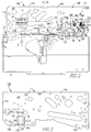
Figure 1 is an isometric view of a circuit breaker and trip actuator assembly therefor, in accordance with an embodiment of the invention, also showing an accessory tray for the circuit breaker in simplified form in phantom line drawing; -
Figure 2 is a side elevation view of the circuit breaker and trip actuator assembly therefor ofFigure 1 , showing portions of the circuit breaker in block form; -
Figure 3 is a side elevation view of the side plate and trip actuator ofFigure 2 ; -
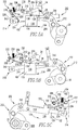
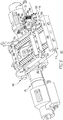
Figure 4 is an isometric view of the trip actuator assembly ofFigure 1 , also showing the pole shaft and cradle assembly of the circuit breaker operating mechanism; -
Figure 5A is a right side elevation view of the trip actuator assembly, and pole shaft and cradle assembly ofFigure 4 , with each component shown in its respective position corresponding to the circuit breaker being closed; -
Figures 5B and 5C are right and left side elevation views, respectively, of the trip actuator assembly, and pole shaft and cradle assembly ofFigure 5A , modified to show each component in its respective position corresponding to the circuit breaker being open; -
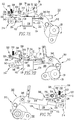
Figure 6 is an isometric view of a trip actuator assembly in accordance with another embodiment of the invention, also showing the pole shaft and cradle assembly of the circuit breaker operating mechanism; -
Figure 7A is a right side elevation view of the trip actuator assembly, and pole shaft and cradle assembly ofFigure 6 , with each component shown in its respective position corresponding to the circuit breaker being closed; and -
Figures 7B and 7C are right and left side elevation views, respectively, of the trip actuator assembly, and pole shaft and cradle assembly ofFigure 7A , modified to show each component in its respective position corresponding to the circuit breaker being open. - For purposes of illustration, embodiments of the invention will be described as applied to low-voltage circuit breakers, although it will become apparent that they could also be applied to a wide variety of electrical switching apparatus (e.g., without limitation, circuit switching devices and other circuit interrupters, such as contactors, motor starters, motor controllers and other load controllers) other than low-voltage circuit breakers and other than low-voltage electrical switching apparatus.
- Directional phrases used herein, such as, for example, left, right, top, bottom, upper, lower, front, back, clockwise and counterclockwise and derivatives thereof, relate to the orientation of the elements shown in the drawings and are not limiting upon the claims unless expressly recited therein.
- As employed herein, the terms "actuator" and "actuating element" refer to any known or suitable output mechanism (e.g., without limitation, trip actuator; solenoid) for an electrical switching apparatus (e.g., without limitation, circuit switching devices, circuit breakers and other circuit interrupters, such as contactors, motor starters, motor controllers and other load controllers) and/or the element (e.g., without limitation, stem; plunger; lever; paddle; arm) of such mechanism which moves in order to manipulate another component of the electrical switching apparatus.
- As employed herein, the term "fastener" shall mean a separate element or elements which is/are employed to connect or tighten two or more components together, and expressly includes, without limitation, rivets, pins, screws, bolts and the combinations of bolts and nuts (e.g., without limitation, lock nuts) and bolts, washers and nuts.
- As employed herein, the term "aperture" refers to any known or suitable passageway into or through a component and expressly includes, but is not limited to, openings, holes, gaps, slots, slits, recesses, and cut-outs.
- As employed herein, the term "trip condition" refers to any electrical event that results in the initiation of a circuit breaker operation in which the separable contacts of the circuit breaker are tripped open, and expressly includes, but is not limited to, electrical fault conditions such as, for example, current overloads, short circuits, abnormal voltage and other fault conditions, receipt of an input trip signal, and a trip coil being energized.
- As employed herein, the statement that two or more parts are "coupled" together shall mean that the parts are joined together either directly or joined through one or more intermediate parts.
- As employed herein, the term "number" shall mean one or an integer greater than one (i.e., a plurality).
-
Figure 1 shows an electrical switching apparatus such as, for example, a low-voltage circuit breaker 2, and atrip actuator assembly 100 and a trip actuator resetassembly 200 therefor. Thecircuit breaker 2 includes a housing 4 having a mounting surface 6, separable contacts 8 (shown in simplified form inFigure 2 ) enclosed by the housing 4, and an operating mechanism 10 (shown in simplified form inFigure 2 ), which is structured to open and close the separable contacts 8 (Figure 2 ). - The
trip actuator assembly 100 includes a trip actuator 102 (e.g., without limitation, a solenoid 102), which is structured to be cooperable with the circuit breaker operating mechanism 10 (Figure 2 ), and aplanar member 104. Theplanar member 104 has first and second ends 110,112, first and second edges 114,116, and at least one aperture 118,120. Theplanar member 104 of theexample circuit breaker 2 shown and described herein, is afirst side plate 104 having first and second apertures 118,120. Theexample circuit breaker 2 also includes asecond side plate 106. Thetrip actuator 102 is structured to be at least partially disposed within thefirst aperture 118 between thefirst side plate 104 and the mounting surface 6 of the housing 4. More specifically, thetrip actuator 102 includes anenclosure 130 having afirst end 132 with an actuating element 138 (e.g., without limitation, a plunger), and asecond end 134 disposed opposite and distal from thefirst end 132. When thetrip actuator 102 is removably coupled to the mounting surface 6 of the circuit breaker housing 4, as shown inFigure 1 (see alsoFigure 3 ), thefirst end 132 of thetrip actuator enclosure 130 is engaged by thefirst side plate 104 at theaperture 118 thereof, and thesecond end 134 of thetrip actuator enclosure 130 is disposed adjacent the mounting surface 6 of the circuit breaker housing 4. - The
first end 132 of thetrip actuator enclosure 130 further includes arecess 140, as shown inFigures 1 ,3 (shown in hidden line drawing), 4 and 6. As shown inFigure 3 , thefirst aperture 118 of the examplefirst side plate 104 is a cutout having afirst edge 122, asecond edge 124, and a top 126. The top 126 of thefirst aperture 118 includes aprotrusion 128 which extends into therecess 140 of thefirst end 132 of thetrip actuator enclosure 130, in order to secure thetrip actuator 102 within thefirst aperture 118. Thefirst side plate 104 further includes afirst side 150 and asecond side 152, and theenclosure 130 of thetrip actuator 102 further includes a body, which in the example shown and described herein is acylinder 136. Thecylinder 136 extends between the first and second ends 132,134 of thetrip actuator enclosure 130, and extends through thefirst aperture 118 of thefirst side plate 104 in order to be disposed on both the first and second sides 150,152 of thefirst side plate 104. More specifically, thecylinder 136 has acenter 142. Theplunger 138 of thetrip actuator 102 is disposed in thecenter 142 of thecylinder 136, as shown inFigures 1 and4 . The first portion of thecylinder 136, which is disposed on thefirst side 150 of thefirst side plate 104, is greater than the second portion of thecylinder 136, which is disposed on thesecond side 152 of thefirst side plate 104, in order that theplunger 138 is disposed on thefirst side 150 of thefirst side plate 104, as shown inFigure 1 . - In view of the foregoing, it will be appreciated that disclosed
trip actuator assembly 100 effectively maintains thetrip actuator 102 in a desired position within thecircuit breaker 2. Specifically, it will be appreciated that thetrip actuator 102 is secured directly by thefirst side plate 104 to the mounting surface 6 of the circuit breaker housing 4. Additionally, thefirst side plate 104 is preferably substantially flat and devoid of deformations (e.g., without limitation, bends). It will, therefore, be appreciated that thetrip actuator 102 is secured directly by thefirst side plate 104, without requiring any intermediate component (e.g., without limitation, a mounting bracket), or, for example, a mounting flange. Thus, it is thefirst side plate 104 that, by itself, functions as the mounting element for precisely mounting thetrip actuator 102 within thecircuit breaker 2. This, along with the fact that circuit breaker components which interact with the trip actuator 102 (e.g., without limitation, thecradle assembly 202 and thereset lever 204 of the trip actuator resetassembly 200 discussed hereinbelow with respect toFigures 4 ,5A, 5B ), are directly coupled to thefirst side plate 104, results in precise, consistent operation of thetrip actuator 102. In this manner, the disclosedtrip actuator assembly 100 overcomes the aforementioned disadvantages (e.g., without limitation, misalignment) associated with known trip actuator assembly designs. - As an added benefit, the example
trip actuator assembly 100 also reduces the number of components and/or fasteners required to accurately position thetrip actuator 102 within thecircuit breaker 2, and thereby further simplifies the installation, removal and/or maintenance of thetrip actuator 102. Specifically, as will now be discussed, thefirst side plate 104 removably couples thetrip actuator 102 to the circuit breaker housing 4, without a plurality of separate fasteners. In particular, as shown inFigures 1 and2 , the mounting surface 6 of the circuit breaker housing 4 includes afirst end 12 having a first slot 14 (shown in hidden line drawing inFigure 2 ), and asecond end 16 disposed opposite and distal from thefirst end 12, and including a second slot 18 (shown in hidden line drawing inFigure 2 ). Continuing to refer toFigures 1 and2 , and also toFigure 3 , it will be appreciated that thefirst edge 114 of the examplefirst side plate 104 includes a first extension 154 (shown in hidden line drawing inFigure 2 ) at or about thefirst end 110 of thefirst side plate 104, and asecond extension 156 disposed at or about thesecond end 112 of thefirst side plate 104. Thefirst extension 154 is structured to removably engage the first slot 14, of the circuit breaker housing 4, and thesecond extension 156 is structured to removably engage thesecond slot 18 of the circuit breaker housing 4. Accordingly, it will be appreciated that thefirst extension 154 of the examplefirst side plate 104 is pivotable with respect to the first slot 14, in order that thesecond extension 156 can engage and disengage thesecond slot 18 to relatively easily secure and release, respectively, thetrip actuator 102, as desired. It will, however, be appreciated that thefirst side plate 104 and, in particular, thefirst edge 114 ofsuch side plate 104, could have any known or suitable alternative number and/or configuration of extensions (e.g., 154,156) or other suitable securing mechanism (not shown) structured to suitably engage the circuit breaker housing 4, without departing from the scope of the invention. - As will be described in greater detail hereinbelow, the
example circuit breaker 2 further includes at least one linking member such as, for example and without limitation, thecradle assembly 202 ofFigures 1 ,2 ,4 ,5A, 5B and 5C (see alsocradle assembly 302 ofFigures 6 ,7A, 7B and 7C ) and thereset lever 204 ofFigures 1 ,2 ,4 ,5A, 5B and 5C (see also resetlever 304 ofFigures 6 ,7A, 7B and 7C ). These components are coupled to the operating mechanism 10 (Figure 2 ) and, in particular, the pole shaft 20 (shown in hidden line drawing inFigure 2 ; see alsoFigures 4 ,5A, 5B, 5C ,6 ,7A, 7B and 7C ) of thecircuit breaker 2, and as previously discussed, are also coupled to thefirst side plate 104 of the exampletrip actuator assembly 100. As will be described in greater detail with respect toFigures 4 ,5A, 5B and 5C , thereset lever 204 includes afirst end 206, asecond end 208, and apivot 210 structured to pivotally couple thereset lever 204 to thefirst side 150 of thefirst side plate 104, as shown inFigure 1 . Thecradle assembly 202 is disposed on thesecond side 152 of thefirst side plate 104, as shown inFigures 1 and5C . Thefirst end 206 of thereset lever 204 is cooperable with theplunger 138 of thetrip actuator 102 on thefirst side 150 of thefirst side plate 104. Thesecond end 208 of the example resetlever 204 extends through thesecond aperture 120 of thefirst side plate 104 and cooperates with a portion of thecradle assembly 202 on thesecond side 152 of thefirst side plate 104, as will be discussed. - In order to further secure the
trip actuator 102 in the desired position with respect to thecircuit breaker 2 and, in particular, the operating mechanism 10 (Figure 2 ), the mounting surface 6 of the housing 4 of theexample circuit breaker 2 further includes a number of outwardly extendingprotrusions 30,32 (Figure 1 ). When thetrip actuator 102 is removably coupled to the mounting surface 6, thebody 136 of thetrip actuator enclosure 130, at or about thesecond end 134 thereof, is secured by at least one of the outwardly extendingprotrusions protrusions second end 134 of thetrip actuator enclosure 130 in the example ofFigure 1 . It will, however, be appreciated that any known or suitable alternative number and/or configuration of protrusions or other suitable securing mechanism (not shown) could be employed, without departing from the scope of the invention. It will also be appreciated that thetrip actuator 102 may, for example, "snap" into position between a suitable number of protrusions (e.g., 30,32) to be secured. Theexample protrusion 32 further includes a hole 34, and receives a fastener, such as the screw 36 shown in exploded orientation inFigure 1 . The screw 36 is fastenable within the hole 34 to further secure thetrip actuator 102. - The housing 4 of the
example circuit breaker 2 also includes anaccessory tray 40 which, for economy of disclosure, is shown in simplified form in phantom line drawing inFigure 1 . Theaccessory tray 40 is insertable on the mounting surface 6 of the housing 4, as shown, and is also removable. When theaccessory tray 40 is inserted (shown), it abuts thebody 136 of thetrip actuator enclosure 130, in order to further secure thetrip actuator 102 in the desired position. More specifically, theaccessory tray 40 includes first andsecond edges first edge 42 has an arcuate recess 46 corresponding to thecylindrical body 136 of thetrip actuator enclosure 130. Accordingly, when theaccessory tray 40 is inserted, as shown inFigure 1 , the arcuate recess 46 of theaccessory tray 40 engages and secures a portion of thecylindrical body 136. - In view of the foregoing, it will be appreciated that the disclosed
trip actuator assembly 100 functions to removably secure thetrip actuator 102 in a precise orientation within the circuit breaker 2 (Figures 1 and2 ). In addition to the aforementioned advantages (e.g., without limitation, precise alignment; consistent operation of the trip actuator), precise mounting of thetrip actuator 102 also helps to ensure that thetrip actuator 102 is effectively and consistently reset following a trip of thecircuit breaker 2 in response to a trip condition, as will now be discussed. -
Figures 4 ,5A, 5B and 5C , show the trip actuator resetassembly 200 for thecircuit breaker 2. Specifically, the trip actuator resetassembly 200 includes theaforementioned cradle assembly 202,reset lever 204, andtrip actuator 102, as well as aresilient element 220, and aguide member 230. The cradle assembly includes afirst end 212, which is pivotally coupled to thepole shaft 20 of the circuit breaker 2 (Figures 1 and2 ), and asecond end 214 disposed opposite and distal from thefirst end 212. Thecradle assembly 202 is movable among a first position (Figures 4 and5A ; see also first position ofcradle assembly 302 ofFigure 7A ) corresponding to the separable contacts 8 (Figure 2 ) of the circuit breaker 2 (Figures 1 and2 ) being closed, and a second position (Figures 5B and 5C ; see also second position ofcradle assembly 302 ofFigures 7B and 7C ) corresponding to the separable contacts 8 (Figure 2 ) being open. In response to the trip condition, theplunger 138 of thetrip actuator 102 is structured to move (upward with respect toFigure 5A ) thefirst end 206 of thereset lever 204. Subsequently, thetrip actuator 102 must be reset. - The
resilient element 220 is pivotally coupled to the circuit breaker housing 4 (Figure 1 ). In the example shown and described herein, theresilient element 220 is a leaf spring having afirst end 222 pivotally coupled to thesecond side 152 of thefirst side plate 104 proximate thesecond end 208 of thereset lever 204. Thesecond end 224 of theleaf spring 220 is disposed opposite and distal from thefirst end 222, and anintermediate portion 226 of theleaf spring 220 is disposed between the first and second ends 222,224. When thecradle assembly 202 moves (e.g., pivots clockwise with respect toFigure 5A ) from the first position (Figures 4 and5A ) toward the second position (Figures 5B and 5C ), theguide member 230 guides thecradle assembly 202 into engagement with theresilient element 220, which pivots thereset lever 204. More specifically, thecradle assembly 202 is pulled by thepole shaft 20 and, in response, has a tendency to pivot. However, when thecradle assembly 202 begins to pivot, the top edges of the first and second sides 216,218 (both shown inFigures 1 and4 ) engage theguide member 230, which prevents it from continuing to pivot, instead forcing it to slide into engagement with theresilient element 220, as shown inFigure 4 . In particular, aprotrusion 219, which extends outwardly from thefirst side 216 of thecradle assembly 202 engages and moves theresilient element 220. Theresilient element 220 then pivots thereset lever 204 such that thefirst end 206 of thereset lever 204 depresses theplunger 138 of thetrip actuator 102, thereby resetting thetrip actuator 102. After thetrip actuator 102 has been reset, if thecradle assembly 202 has a tendency to continue to move beyond the second position (Figures 5B and 5C ), theintermediate portion 226 of theresilient element 220 bends, as shown in exaggerated form inFigures 5B and 5C . In this manner, the resilient element 220 (e.g., without limitation, leaf spring) accommodates any additional energy and associated motion (e.g., over-rotation) that thecradle assembly 202 may have. Accordingly, the disclosed trip actuator resetassembly 200 overcomes the aforementioned disadvantages (e.g., without limitation, over-rotation; damage to the plunger 138) associated with known trip actuator reset assemblies. - More specifically, as shown in
Figures 1 and4 , theguide member 230 includes first and second ends 232,234, and in anelongated body 236 extending therebetween. Theelongated body 236 extends between the first and second side plates 104,106 of thecircuit breaker 2, as shown inFigure 1 . The example resetlever 204 further includes a bias element such as, for example and without limitation, thespring 250, which is shown. Thebias element 250 is structured to bias thesecond end 208 of thereset lever 204, in order to bias and thus pivot (e.g., counterclockwise from the perspective ofFigures 4 ,5A and 5B ; clockwise from the perspective ofFigure 5C ) thefirst end 206 of thereset lever 204, toward the position shown inFigures 4 and5A . As partially shown in simplified form in phantom line drawing inFigure 5C , theexample bias element 250 is disposed within the second aperture orhole 120 of the first side plate 104 (see alsoFigures 1 and2 ). In this manner, thefirst end 206 of thereset lever 204 is biased away from theplunger 138 of thetrip actuator 102. - The aforementioned first side 216 (
Figures 4 ,5A and 5B ) of thecradle assembly 202 extends from thepole shaft 20 toward thesecond end 214 of thecradle assembly 202. Theexample cradle assembly 202 also includes a second side 218 (Figure 5C ), which is disposed opposite and spaced apart from thefirst side 216. Afirst cross member 240, which is disposed proximate thefirst end 212 of thecradle assembly 202, extends between the first and second sides 216,218, and is structured not to move independently with respect to the first and second sides 216,218. Asecond cross member 242 is disposed at or about thesecond end 214 of thecradle assembly 202, and is structured to extend between, and be pivotally coupled to, the first and second side plates 104,106 of the circuit breaker 2 (Figures 1 and2 ). Thus, thesecond cross member 242 provides a fixed pivot point for thecradle assembly 202 with respect to the first and second side plates 104,106, and thetrip actuator 102. At least one elongated member such as, for example and without limitation, the first and second rods 244,246 shown inFigure 4 , is/are fixedly coupled to thesecond cross member 242, and extend through thefirst cross member 240. Specifically, as will be appreciated with reference tosecond rod 246 ofFigure 4 , each of the example elongated members 244,246 extend through a corresponding thru hole (only one thruhole 252 is shown inFigure 4 ; see also rods 344,346 extending through thru holes 351,352 inFigure 6 ) in thefirst cross member 240 of thecradle assembly 202. It will, therefore, be appreciated that a portion (e.g., without limitation, first and second sides 216,218;pivot 219; first cross member 240) of thecradle assembly 202 can move on the elongated members 244,246 with respect to a second portion (e.g., without limitation, second cross member 242) of thecradle assembly 202, in order to accommodate movement of thepole shaft 20 and/orcradle assembly 202, for example, during a reset operation of thetrip actuator 102. - In the example of
Figure 4 , the first and second rods 244,246 further include first and second springs 248,249, respectively. The springs 248,249 are disposed between the first and second cross members 240,242 of thecradle assembly 202, and the rods 244,246 pass through the coils of the springs 248,249, respectively. The springs 248,249 have a tendency to bias thecradle assembly 202 toward the second position (Figures 5B and 5C ; see alsocradle assembly 302 shown in the second position inFigures 7B and 7C ). It will, however, be appreciated that such springs (e.g., 248,249) shown and described with respect toFigure 4 are not intended to be a limiting element of the disclosed trip actuator resetassembly 200. For example, thecradle assembly 202 could be devoid of such springs, without departing from the scope of the invention. - The operating mechanism 10 (shown in simplified form in
Figure 2 ) of the example circuit breaker 2 (Figures 1 and2 ) further includes atrip bar 24 andtrip lever 22, both of which are shown in simplified form in phantom line drawing inFigures 1 ,5A and 5B (see alsoFigures 7A and 7B ). Thetrip lever 22 includes afirst end 26, which overlays theplunger 138 of thetrip actuator 102, and asecond end 28, which is coupled to thetrip bar 24. Thefirst end 26 of theexample trip lever 22 is also cooperable with thefirst end 206 of thereset lever 204 of the trip actuator resetassembly 200, in order that thetrip lever 22 and resetlever 204 are movable together in certain modes of operation (e.g., when theplunger 138 of thetrip actuator 102 pushes them, as shown in phantom line drawing inFigure 5A ). More specifically, as partially shown in phantom line drawing inFigure 1 , theexample trip lever 22 is structured to overlay (e.g., without limitation, straddle) thefirst end 206 of thereset lever 204. - An operation of the trip actuator reset
assembly 200 to reset thetrip actuator 102 following a trip condition, will now be discussed with reference toFigures 5A, 5B and 5C . It will be appreciated that except for the distinctions discussed herein, the trip actuator resetassembly 300 discussed hereinbelow with respect toFigures 6 ,7A, 7B and 7C functions in substantially the same manner. Specifically, as previously discussed, the example trip actuator is asolenoid 102 having as its actuating element, aplunger 138. In response to the trip condition, theplunger 138 extends in order to pivot thereset lever 204 and thetrip lever 22, as shown in phantom line drawing inFigure 5A . After the trip condition, theplunger 138 remains extended until it is depressed by thereset lever 204 in order to reset thetrip actuator 102 and thetrip lever 22. Specifically, to begin a reset operation, during which thepole shaft 20 andcradle assembly 202 move from the position shown inFigure 5A toward the position shown inFigures 5B and 5C , theprotrusion 219 of thecradle assembly 202 engages the resilient element 220 (e.g., without limitation, leaf spring) and pivots it about itsfirst end 222, as previously discussed. Theintermediate portion 226 of theresilient element 220 then engages thesecond end 208 of thereset lever 204, thereby pivoting thereset lever 204 until thefirst end 206 of thereset lever 204 engages and depresses theplunger 138, as shown inFigure 5B . When theplunger 138 is fully depressed, thetrip actuator 102 is reset. Simultaneously, thetrip lever 22, which in the example shown and described herein is cooperable with (e.g., overlays) thereset lever 204, is also reset. - Unique to the disclosed trip actuator reset
assembly 200 is that, after thetrip actuator 102 is reset, if thecradle assembly 202 has a tendency to continue to move, for example, thereby having a tendency to over-rotate thereset lever 204 and potentially damage theplunger 138 and/ortrip actuator 102 or a component (e.g., without limitation, cradle assembly 202) of the trip actuator resetassembly 200, theintermediate portion 226 of theresilient element 220 advantageously bends to absorb such movement, as previously discussed. The disclosed trip indicator resetassembly 200, therefore, resists undesirable consequences, for example, associated with over-rotation of thecradle assembly 202. - It will, however, be appreciated that the trip actuator reset assembly (e.g., 200) and components (e.g., without
limitation cradle assembly 202; resetlever 204; resilient element 220) could comprise any known or suitable alternative configuration. For example,Figures 6 ,7A, 7B and 7C show a trip actuator resetassembly 300 which is substantially similar to the trip actuator resetassembly 200 discussed with respect toFigures 4 ,5A, 5B and 5C , but includes arigid element 320 as opposed to theresilient element 220 of trip actuator resetassembly 200. It will be appreciated that like features of the trip actuator resetassembly 300 are numbered substantially the same as those previously discussed with respect to trip actuator resetassembly 200, but using 300 series reference numbers instead of 200 series reference numbers. For example, thecradle assembly 302, includes first and second ends 312,314, first and second sides 316,318, first and second cross members 340,342, and first and second rods 344,346, all of which are substantially similar to the same features previously discussed in connection with trip actuator resetassembly 200 ofFigures 4 ,5A, 5B and 5C . For economy of disclosure, certain aspects of the trip actuator resetassembly 300 which are substantially the same as trip actuator resetassembly 200, discussed hereinabove, will not be repetitively discussed. - In addition to the distinction of the
rigid element 320 which, unlike the aforementioned resilient element 220 (e.g., without limitation, leaf spring) is not intended to bend or otherwise deflect, the trip actuator resetassembly 300 is further different from trip actuator resetassembly 200 in that the springs 348,349 or suitable equivalent resilient element(s) is/are required elements of thecradle assembly 302. This is because any additional movement (e.g., without limitation, over-rotation) of, for example, thecradle assembly 302, that is experienced during the reset operation, must be accommodated by the springs 348,349. In other words, after thetrip actuator 102 has been reset, if thecradle assembly 302 continues to move beyond the second position, as shown in phantom line drawing inFigure 7B , then the springs 348,349 (both are shown inFigure 6 ) of thecradle assembly 302 flex (e.g., extend) to accommodate the additional motion, and thereby resist damage to components of the trip actuator resetassembly 300 such as, for example and without limitation, theplunger 138, thetrip actuator 102, thereset lever 304 and/or thecradle assembly 302. Thus, as will be appreciated by comparingFigure 7B to Figure 5B , previously discussed in connection with trip actuator resetassembly 200, rather than bending or otherwise deflecting theresilient element 220, as shown in exaggerated form inFigure 5B , in order to absorb additional motion of thecradle assembly 202, theintermediate portion 326 of therigid element 320 of the example ofFigure 7B does not bend or otherwise deflect. Instead, thecradle assembly 302 itself and, in particular, the springs 348,349 thereof, absorb the additional movement. It will be appreciated that the remainder of the operation of trip actuator resetassembly 300 to reset thetrip actuator 102 andtrip lever 22 is substantially the same as for trip actuator resetassembly 200, previously discussed. It will also be appreciated that, rather than, or in addition to, the springs 348,349, the opening spring (not shown) of the circuit breaker (Figures 1 and2 ) could be employed to accommodate the excess movement of thecradle assembly 302, for example, by allowing thecradle assembly 302 to flex. - It will, therefore, be appreciated that the disclosed trip actuator reset assemblies 200,300 can accommodate, for example and without limitation, misalignment and/or over-rotation associated therewith, in order to effectively, consistently reset the
trip actuator 102 of the circuit breaker (Figures 1 and2 ). It will also be appreciated that the components of the trip actuator reset assemblies 200,300 could be shaped and configured in a wide variety of alternative arrangements (not shown) in order to achieve this goal in accordance with the invention. For example, although therigid element 320 shown and described in the example ofFigures 6 ,7A, 7B and 7C is an elongated member having afirst end 322 pivotally coupled to thesecond side 152 of the first side plate 104 (shown in phantom line drawing inFigure 7C ), asecond end 324 disposed opposite and distal from thefirst end 322, and theintermediate portion 326 therebetween, it could alternatively have any suitable shape and/or configuration (not shown). For instance, a protrusion (not shown) of the cradle assembly (e.g., 302) itself could pivot thereset lever 304, thus eliminating the need for a separate rigid element (e.g., 320). -
- 2
- circuit breaker
- 4
- housing
- 6
- mounting surface
- 8
- separable contacts
- 10
- operating mechanism
- 12
- first end of mounting surface
- 14
- first slot
- 16
- second end of mounting surface
- 18
- second slot
- 20
- pole shaft
- 22
- trip lever
- 24
- trip bar
- 26
- first end of trip lever
- 28
- second end of trip lever
- 30
- protrusion
- 32
- protrusion
- 34
- hole
- 36
- screw
- 40
- accessory tray
- 42
- first edge of accessory tray
- 44
- second edge of accessory tray
- 46
- arcuate recess
- 100
- trip actuator assembly
- 102
- trip actuator
- 104
- first side plate
- 106
- second side plate
- 110
- first end of first side plate
- 112
- second end of first side plate
- 114
- first edge of first side plate
- 116
- second edge of first side plate
- 118
- first aperture of first side plate
- 120
- second aperture of first side plate
- 122
- first edge of first aperture
- 124
- second edge of first aperture
- 126
- top of first aperture
- 128
- protrusion
- 130
- enclosure of trip actuator
- 132
- first end of enclosure
- 134
- second end of enclosure
- 136
- body of enclosure
- 138
- plunger
- 140
- recess of trip enclosure
- 142
- center of body
- 150
- first side of first side plate
- 152
- second side of first side plate
- 154
- first extension
- 156
- second extension
- 200
- trip actuator reset assembly
- 202
- cradle assembly
- 204
- reset lever
- 206
- first end of reset lever
- 208
- second end of reset lever
- 210
- pivot
- 212
- first end of cradle assembly
- 214
- second end of cradle assembly
- 216
- first side of cradle assembly
- 218
- second side of cradle assembly
- 219
- protrusion
- 220
- resilient element
- 222
- first end of leaf spring
- 224
- second end of leaf spring
- 226
- intermediate portion of leaf spring
- 230
- guide member
- 232
- first end of guide member
- 234
- second end of guide member
- 236
- elongated body
- 240
- first cross member of cradle assembly
- 242
- second cross member of cradle assembly
- 244
- first rod
- 246
- second rod
- 248
- first spring
- 249
- second spring
- 250
- bias element of reset lever
- 252
- thru hole of second cross member
- 300
- trip actuator reset assembly
- 302
- cradle assembly
- 304
- reset lever
- 306
- first end of reset lever
- 308
- second end of reset lever
- 310
- pivot
- 312
- first end of cradle assembly
- 314
- second end of cradle assembly
- 316
- first side of cradle assembly
- 318
- second side of cradle assembly
- 319
- protrusion
- 320
- resilient element
- 322
- first end of leaf spring
- 324
- second end of leaf spring
- 326
- intermediate portion of leaf spring
- 330
- guide member
- 332
- first end of guide member
- 334
- second end of guide member
- 336
- elongated body
- 340
- first cross member of cradle assembly
- 342
- second cross member of cradle assembly
- 344
- first rod
- 346
- second rod
- 348
- first spring
- 349
- second spring
- 350
- bias element of reset lever
- 351
- thru hole of first cross member
- 352
- thru hole of second cross member
Claims (12)
- A trip actuator reset assembly (200) for an electrical switching apparatus (2) including a housing (4), separable contacts (8) enclosed by said housing (4), and an operating mechanism (10) structured to open and close said separable contacts (8), said operating mechanism (10) including a pole shaft (20), said trip actuator reset assembly (200) comprising:a cradle assembly (202) including a first end (212) structured to be pivotably coupled to said pole shaft (20), and a second end (214) disposed opposite and distal from the first end (212), said cradle assembly (202) being structured to be movable among a first position corresponding to said separable contacts (8) being closed, and a second position corresponding to said separable contacts (8) being open;a reset lever (204) including a first end (206), a second end (208) disposed opposite and distal from the first end (206) of said reset lever (204), and a pivot (210) structured to pivotably couple said reset lever (204) to said housing (4);a trip actuator (102) including an actuating element (138) which, in response to a trip condition, is structured to move the first end (206) of said reset lever (204); characterized by a resilient element (220) structured to be pivotably coupled to said housing (4) proximate the second end (208) of said reset lever (204); anda guide member (230),wherein, after said trip condition, said actuating element (138) of said trip actuator (102) is structured to be reset,wherein, when said cradle assembly (202) moves from said first position toward said second position, said guide member (230) guides said cradle assembly (202) into engagement with said resilient element (220) which pivots said reset lever (204),wherein, when said resilient element (220) pivots said reset lever (204), the first end (206) of said reset lever (204) moves said actuating element (138) of said trip actuator (102), thereby resetting said trip actuator (102),wherein, after said trip actuator (102) has been reset, if said cradle assembly (202) continues to move beyond said second position, then said resilient element (220) bends to accommodate any additional motion of said cradle assembly (202), andwherein said housing (4) of said electrical switching apparatus (2) includes a mounting surface (6), a first side plate (104) extending outwardly from said mounting surface (6), and a second side plate (106) extending outwardly from said mounting surface (6); wherein said guide member (230) includes a first end (232), a second end (234) disposed opposite and distal from the first end (232) of said guide member (230), and an elongated body (236) extending between the first end (232) of said guide member (230) and the second end (234) of said guide member (230); and wherein said elongated body (236) is structured to extend between said first side plate (104) and said second side plate (106).
- The trip actuator reset assembly (200) of claim 1 wherein said first side plate (104) includes a first side (150) and a second side (152); wherein said actuating element (138) of said trip actuator (102) is structured to be disposed on the first side (150) of said first side plate (104); and wherein said pivot (210) of said reset lever (204) is structured to be pivotably coupled to the first end (232) of said guide member (230) at or about the first side (150) of said first side plate (104).
- The trip actuator reset assembly (200) of claim 2 wherein said reset lever (204) further includes a bias element (250); wherein said first side (104) plate further includes a hole (120); wherein the second end (208) of said reset lever (204) is structured to extend from the first side (150) of said first side plate (104) through said hole (120) of said first side plate (104) and beyond the second side (152) of said first side plate (104); and wherein said bias element (250) is structured to be disposed within said hole (120) of said first side plate (104), in order to bias the second end (208) of said reset lever (204) away from said actuating element (138) of said trip actuator (102).
- The trip actuator reset assembly (200) of claim 2 wherein said cradle assembly (202) comprises a first side (216) structured to extend from said pole shaft (20) toward the second end (214) of said cradle assembly (202), a second side (218) disposed opposite and spaced from the first side (216) of said cradle assembly (202), a first cross member (240) disposed proximate the first end (212) of said cradle assembly (202), a second cross member (242) disposed at or about the second end (214) of said cradle assembly (202), and at least one elongated member (244,246) fixedly coupled to said second cross member (242) and extending through said first cross member (240); wherein said first cross member (240) extends between the first side (216) of said cradle assembly (202) and the second side (218) of said cradle assembly (202); wherein said first cross member (242) does not move independently with respect to the first side (216) of said cradle assembly (202) and the second side (218) of said cradle assembly (202); and wherein said second cross member (242) is structured to extend between and be pivotably coupled to said first side plate (104) and said second side plate (106), thereby providing a fixed pivot point for said cradle assembly (202) with respect to said first side plate (104) and said second side plate (106).
- The trip actuator assembly (200) of claim 4 wherein, when said cradle assembly (202) is moved toward said second position, the first side (216) of said cradle assembly (202), the second side (218) of said cradle assembly (202), and said first cross member (240) extending therebetween are movable with respect to said second cross member (242) and said at least one elongated member (244,246) fixedly coupled to said second cross member (242).
- The trip actuator assembly (200) of claim 5 wherein said at least one elongated member is a first rod (244) and a second rod (246); wherein said cradle assembly (202) further comprises a first spring (248) disposed on said first rod (246), and a second spring (249) disposed on said second rod (246); and wherein said first spring (248) and said second spring (249) bias said cradle assembly (202) toward said second position.
- The trip actuator reset assembly (200) of claim 4 wherein the first side (216) of said cradle assembly (202) further comprises a protrusion (219) extending outwardly from the first side (216) of said cradle assembly (202) toward said first side plate (104); wherein said resilient element (220) is pivotably coupled to the second side (152) of said first side plate (104); and wherein, when said cradle assembly (202) moves toward said second position, said protrusion (219) engages and moves said resilient element (220).
- The trip actuator reset assembly (200) of claim 7 wherein said operating mechanism (10) of said electrical switching apparatus further includes a trip lever (22); and wherein, when said protrusion (219) engages and moves said resilient element (220) and said cradle assembly (202) continues to move toward said second position, said resilient element (220) engages the second end (208) of said reset lever (204) and pivots said reset lever (204) about said pivot (210), in order that the first end (206) of said reset lever (204) moves said actuating element (138) of said trip actuator (102).
- The trip actuator reset assembly (200) of claim 1 wherein said actuating element (138) of said trip actuator (102) is a plunger (138); wherein, in response to said trip condition, said plunger (138) is structured to extend in order to pivot said reset lever (204) and said trip lever (22); and wherein, after said trip condition, said plunger (138) remains extended until it is depressed by said reset lever (204) in order to reset said trip actuator (102) and said trip lever (22).
- The trip actuator reset assembly (200) of claim 9 wherein said resilient element is a leaf spring (220) having a first end (222) pivotably coupled to the second side (152) of said first side plate (104), a second end (224) disposed opposite and distal from the first end (222), and an intermediate portion (226) extending between the first end (222) and the second end (224); wherein, when said cradle assembly (202) is moved toward said second position, said intermediate portion (226) of said resilient element (220) engages the second end (208) of said reset lever (204), thereby pivoting said reset lever (204); wherein, as said cradle assembly (202) moves into said second position, said reset lever (204) is structured to continue to pivot until the first end (206) of said reset lever (204) completely depresses said plunger (138), thereby resetting said trip actuator (102) and said trip lever (22); and wherein, after said trip actuator (102) is reset, if said cradle assembly (202) continues to move, then said intermediate portion (226) of said resilient element (220) bends to absorb such movement.
- An electrical switching apparatus (2) which comprises an operating mechanism (10) including a pole shaft (20) and being structured to open and close separable contacts (8) enclosed by a housing (4); and a trip actuator reset assembly (200) as claimed in any of claims 1 to 10:
- The electrical switching apparatus (2) of claim 11 wherein said electrical switching apparatus is a circuit breaker (2); wherein said operating mechanism (10) of said circuit breaker (2) further comprises a trip bar (24) and a trip lever (22) extending outwardly from said trip bar (24); wherein said trip lever (22) includes a first end (26) which overlays said actuating element (138) of said trip actuator (102), and a second end (28) of said trip lever (22) being coupled to said trip bar (24); and wherein the first end (26) of said trip lever (22) is cooperable with the first end (206) of said reset lever (204) of said trip actuator reset assembly (200).
Applications Claiming Priority (1)
| Application Number | Priority Date | Filing Date | Title |
|---|---|---|---|
| US11/696,812 US7518476B2 (en) | 2007-04-05 | 2007-04-05 | Electrical switching apparatus and trip actuator reset assembly therefor |
Publications (3)
| Publication Number | Publication Date |
|---|---|
| EP1978538A2 EP1978538A2 (en) | 2008-10-08 |
| EP1978538A3 EP1978538A3 (en) | 2010-03-24 |
| EP1978538B1 true EP1978538B1 (en) | 2017-06-21 |
Family
ID=39495046
Family Applications (1)
| Application Number | Title | Priority Date | Filing Date |
|---|---|---|---|
| EP08006927.1A Active EP1978538B1 (en) | 2007-04-05 | 2008-04-07 | Electrical switching apparatus and trip actuator reset assembly therefor |
Country Status (4)
| Country | Link |
|---|---|
| US (1) | US7518476B2 (en) |
| EP (1) | EP1978538B1 (en) |
| CN (1) | CN101350273B (en) |
| CA (1) | CA2628436A1 (en) |
Families Citing this family (4)
| Publication number | Priority date | Publication date | Assignee | Title |
|---|---|---|---|---|
| US7646270B2 (en) * | 2007-05-04 | 2010-01-12 | Eaton Corporation | Electrical switching apparatus, and yoke assembly and spring assembly therefor |
| US7586394B2 (en) * | 2007-07-10 | 2009-09-08 | Eaton Corporation | Electrical switching apparatus, and trip actuator reset assembly and lever arm assembly therefor |
| US8053694B2 (en) * | 2009-04-15 | 2011-11-08 | Eaton Corporation | Mechanism or resettable trip indicator mechanism for a circuit interrupter and circuit interrupter including the same |
| US8183483B2 (en) * | 2009-09-28 | 2012-05-22 | Eaton Corporation | Electrical switching apparatus and shaft assembly therefor |
Family Cites Families (24)
| Publication number | Priority date | Publication date | Assignee | Title |
|---|---|---|---|---|
| US3152232A (en) * | 1960-02-29 | 1964-10-06 | Ite Circuit Breaker Ltd | Circuit breaker having bimetal rigidly secured to cradle |
| US3360751A (en) * | 1965-10-21 | 1967-12-26 | Gen Electric | Circuit breaker undervoltage trip device with magnet resetting means |
| US4000478A (en) * | 1975-10-30 | 1976-12-28 | General Electric Company | Static trip molded case circuit breaker including trip interlock |
| US4064469A (en) * | 1976-04-12 | 1977-12-20 | I-T-E Imperial Corporation | Interchangeable solid state and thermal-magnetic trip units |
| US4097831A (en) * | 1977-01-21 | 1978-06-27 | General Electric Company | Circuit breaker accessory tripping apparatus |
| US4679019A (en) * | 1986-05-14 | 1987-07-07 | General Electric Company | Trip actuator for molded case circuit breakers |
| US5057806A (en) * | 1988-08-01 | 1991-10-15 | Westinghouse Electric Corp. | Crossbar assembly |
| NL9102154A (en) * | 1991-12-20 | 1993-07-16 | Holec Syst & Componenten | ELECTRICAL SWITCH, IN PARTICULAR A LOAD OR POWER SWITCH. |
| CH690345A5 (en) * | 1996-06-05 | 2000-07-31 | Wen Fong Lee | Sealed electric switch assembly, especially for power switching |
| DE19716380C1 (en) * | 1997-04-18 | 1998-10-08 | Siemens Ag | Electromagnetic switching device |
| US6034586A (en) * | 1998-10-21 | 2000-03-07 | Airpax Corporation, Llc | Parallel contact circuit breaker |
| DE19903911B4 (en) * | 1999-02-01 | 2004-09-23 | Ge Power Controls Polska Sp.Z.O.O. | Tripping device for switches and switch contact arrangement |
| FR2799573B1 (en) * | 1999-10-11 | 2001-12-14 | Schneider Electric Ind Sa | CIRCUIT BREAKER CONTROL MECHANISM |
| US6317018B1 (en) * | 1999-10-26 | 2001-11-13 | General Electric Company | Circuit breaker mechanism |
| US6172584B1 (en) * | 1999-12-20 | 2001-01-09 | General Electric Company | Circuit breaker accessory reset system |
| US6346868B1 (en) * | 2000-03-01 | 2002-02-12 | General Electric Company | Circuit interrupter operating mechanism |
| US6373357B1 (en) * | 2000-05-16 | 2002-04-16 | General Electric Company | Pressure sensitive trip mechanism for a rotary breaker |
| US20020130744A1 (en) * | 2001-03-16 | 2002-09-19 | Gerd Jodehl | Tripping device for a circuit breaker |
| ES2199647B1 (en) * | 2001-09-07 | 2005-05-01 | Ge Power Controls Iberica, S.L. | MECHANISM OF SHOT AND REARME FOR ELECTRICAL AND SIMILAR DEVICES. |
| US6980069B2 (en) * | 2002-04-18 | 2005-12-27 | General Electric Company | Magnetic device for a magnetic trip unit |
| US6903635B2 (en) * | 2003-05-13 | 2005-06-07 | General Electric Company | Circuit breaker interface mechanism for auxiliary switch accessory |
| US6921873B2 (en) | 2003-08-01 | 2005-07-26 | Eaton Corporation | Circuit breaker trip unit employing a rotary plunger |
| US6803535B1 (en) * | 2004-02-19 | 2004-10-12 | Eaton Corporation | Circuit breaker with a visual indication of a trip |
| US7132911B2 (en) * | 2005-01-25 | 2006-11-07 | Rong-Lin G Chung | Breaker for protecting electric facilities |
-
2007
- 2007-04-05 US US11/696,812 patent/US7518476B2/en active Active
-
2008
- 2008-04-03 CN CN2008101611401A patent/CN101350273B/en active Active
- 2008-04-03 CA CA002628436A patent/CA2628436A1/en not_active Abandoned
- 2008-04-07 EP EP08006927.1A patent/EP1978538B1/en active Active
Also Published As
| Publication number | Publication date |
|---|---|
| CN101350273A (en) | 2009-01-21 |
| EP1978538A3 (en) | 2010-03-24 |
| EP1978538A2 (en) | 2008-10-08 |
| CA2628436A1 (en) | 2008-10-05 |
| US7518476B2 (en) | 2009-04-14 |
| US20080245649A1 (en) | 2008-10-09 |
| CN101350273B (en) | 2013-01-02 |
Similar Documents
| Publication | Publication Date | Title |
|---|---|---|
| EP1978540B1 (en) | Electrical switching apparatus and trip actuator assembly therefor | |
| EP1978539B1 (en) | Electrical switching apparatus, and trip actuator assembly and reset assembly therefor | |
| US7800468B2 (en) | Electrical switching apparatus, and accessory module and strain relief mechanism therefor | |
| EP1975963B1 (en) | Electrical switching apparatus and accessory assembly therefor | |
| EP1978538B1 (en) | Electrical switching apparatus and trip actuator reset assembly therefor | |
| EP1975955B1 (en) | Electrical switching apparatus and accessory tray therefor | |
| US7645953B2 (en) | Electrical switching apparatus, and accessory module and electrical conductor mount therefor | |
| EP1975968B1 (en) | Electrical switching apparatus and trip bar therefor | |
| US7868262B2 (en) | Electrical switching apparatus, and sub-assembly and auxiliary switch tray therefor | |
| US7586394B2 (en) | Electrical switching apparatus, and trip actuator reset assembly and lever arm assembly therefor | |
| EP3127130B1 (en) | Electrical switching apparatus and dampening assembly therefor |
Legal Events
| Date | Code | Title | Description |
|---|---|---|---|
| PUAI | Public reference made under article 153(3) epc to a published international application that has entered the european phase |
Free format text: ORIGINAL CODE: 0009012 |
|
| AK | Designated contracting states |
Kind code of ref document: A2 Designated state(s): AT BE BG CH CY CZ DE DK EE ES FI FR GB GR HR HU IE IS IT LI LT LU LV MC MT NL NO PL PT RO SE SI SK TR |
|
| AX | Request for extension of the european patent |
Extension state: AL BA MK RS |
|
| PUAL | Search report despatched |
Free format text: ORIGINAL CODE: 0009013 |
|
| AK | Designated contracting states |
Kind code of ref document: A3 Designated state(s): AT BE BG CH CY CZ DE DK EE ES FI FR GB GR HR HU IE IS IT LI LT LU LV MC MT NL NO PL PT RO SE SI SK TR |
|
| AX | Request for extension of the european patent |
Extension state: AL BA MK RS |
|
| RIC1 | Information provided on ipc code assigned before grant |
Ipc: H01H 71/10 20060101AFI20080618BHEP Ipc: H01H 71/52 20060101ALI20100218BHEP |
|
| 17P | Request for examination filed |
Effective date: 20100924 |
|
| 17Q | First examination report despatched |
Effective date: 20101022 |
|
| AKX | Designation fees paid |
Designated state(s): DE FR GB IT |
|
| GRAP | Despatch of communication of intention to grant a patent |
Free format text: ORIGINAL CODE: EPIDOSNIGR1 |
|
| INTG | Intention to grant announced |
Effective date: 20170105 |
|
| GRAS | Grant fee paid |
Free format text: ORIGINAL CODE: EPIDOSNIGR3 |
|
| GRAA | (expected) grant |
Free format text: ORIGINAL CODE: 0009210 |
|
| AK | Designated contracting states |
Kind code of ref document: B1 Designated state(s): DE FR GB IT |
|
| REG | Reference to a national code |
Ref country code: GB Ref legal event code: FG4D |
|
| REG | Reference to a national code |
Ref country code: DE Ref legal event code: R096 Ref document number: 602008050730 Country of ref document: DE |
|
| REG | Reference to a national code |
Ref country code: FR Ref legal event code: PLFP Year of fee payment: 11 Ref country code: DE Ref legal event code: R097 Ref document number: 602008050730 Country of ref document: DE |
|
| PLBE | No opposition filed within time limit |
Free format text: ORIGINAL CODE: 0009261 |
|
| STAA | Information on the status of an ep patent application or granted ep patent |
Free format text: STATUS: NO OPPOSITION FILED WITHIN TIME LIMIT |
|
| PGFP | Annual fee paid to national office [announced via postgrant information from national office to epo] |
Ref country code: GB Payment date: 20180321 Year of fee payment: 11 |
|
| 26N | No opposition filed |
Effective date: 20180322 |
|
| REG | Reference to a national code |
Ref country code: GB Ref legal event code: 732E Free format text: REGISTERED BETWEEN 20181115 AND 20181130 |
|
| GBPC | Gb: european patent ceased through non-payment of renewal fee |
Effective date: 20190407 |
|
| PG25 | Lapsed in a contracting state [announced via postgrant information from national office to epo] |
Ref country code: GB Free format text: LAPSE BECAUSE OF NON-PAYMENT OF DUE FEES Effective date: 20190407 |
|
| REG | Reference to a national code |
Ref country code: DE Ref legal event code: R082 Ref document number: 602008050730 Country of ref document: DE Representative=s name: WAGNER & GEYER PARTNERSCHAFT MBB PATENT- UND R, DE Ref country code: DE Ref legal event code: R081 Ref document number: 602008050730 Country of ref document: DE Owner name: EATON INTELLIGENT POWER LIMITED, IE Free format text: FORMER OWNER: EATON CORPORATION, CLEVELAND, OHIO, US |
|
| PGFP | Annual fee paid to national office [announced via postgrant information from national office to epo] |
Ref country code: FR Payment date: 20230321 Year of fee payment: 16 |
|
| PGFP | Annual fee paid to national office [announced via postgrant information from national office to epo] |
Ref country code: IT Payment date: 20230322 Year of fee payment: 16 |
|
| P01 | Opt-out of the competence of the unified patent court (upc) registered |
Effective date: 20230521 |
|
| PGFP | Annual fee paid to national office [announced via postgrant information from national office to epo] |
Ref country code: DE Payment date: 20230321 Year of fee payment: 16 |