EP1978340A2 - Temperature sensor with improved resistance against vibration - Google Patents
Temperature sensor with improved resistance against vibration Download PDFInfo
- Publication number
- EP1978340A2 EP1978340A2 EP08153964A EP08153964A EP1978340A2 EP 1978340 A2 EP1978340 A2 EP 1978340A2 EP 08153964 A EP08153964 A EP 08153964A EP 08153964 A EP08153964 A EP 08153964A EP 1978340 A2 EP1978340 A2 EP 1978340A2
- Authority
- EP
- European Patent Office
- Prior art keywords
- cover
- storage space
- sheath
- end portion
- wires
- Prior art date
- Legal status (The legal status is an assumption and is not a legal conclusion. Google has not performed a legal analysis and makes no representation as to the accuracy of the status listed.)
- Withdrawn
Links
Images


Classifications
-
- G—PHYSICS
- G01—MEASURING; TESTING
- G01K—MEASURING TEMPERATURE; MEASURING QUANTITY OF HEAT; THERMALLY-SENSITIVE ELEMENTS NOT OTHERWISE PROVIDED FOR
- G01K13/00—Thermometers specially adapted for specific purposes
- G01K13/02—Thermometers specially adapted for specific purposes for measuring temperature of moving fluids or granular materials capable of flow
-
- G—PHYSICS
- G01—MEASURING; TESTING
- G01K—MEASURING TEMPERATURE; MEASURING QUANTITY OF HEAT; THERMALLY-SENSITIVE ELEMENTS NOT OTHERWISE PROVIDED FOR
- G01K1/00—Details of thermometers not specially adapted for particular types of thermometer
- G01K1/08—Protective devices, e.g. casings
-
- G—PHYSICS
- G01—MEASURING; TESTING
- G01K—MEASURING TEMPERATURE; MEASURING QUANTITY OF HEAT; THERMALLY-SENSITIVE ELEMENTS NOT OTHERWISE PROVIDED FOR
- G01K2205/00—Application of thermometers in motors, e.g. of a vehicle
- G01K2205/04—Application of thermometers in motors, e.g. of a vehicle for measuring exhaust gas temperature
Definitions
- the present invention relates to temperature sensors with improved resistance against vibration, and methods of manufacturing the same.
- Temperature sensors with a thermistor as a thermo-sensitive element are preferably installed in a passage through which exhaust gas flows; this passage is formed inside of, for instance, a catalytic converter for exhaust emission control systems, or an exhaust pipe. Such a temperature sensor is operative to measure, with the thermistor, the temperature of exhaust gas flowing through such a passage.
- Thermistors are sensitive to temperature, an electrical characteristic changing as the temperature changes.
- a common temperature sensor is for example disclosed in Japanese Patent Application Publication No. 2004-317499 .
- the temperature sensor disclosed in the Patent Application Publication consists of a cylindrical housing and a sensing element.
- the sensing element is installed in the cylindrical housing such that one end portion of the sensing element projects therefrom.
- the sensing element is provided at the head of its overhanging portion with a thermistor.
- the sensing element is provided with a pair of core wires covered with a sheath by which the core wires are electrically insulated. One end of each of the core wires projects from one end of the sheath.
- the one ends of the pair of core wires are connected with a pair of electrode wires mounted in the thermistor, and the other ends thereof are connected with a control circuit.
- the thermistor with the paired electrode wires and the paired core wires are installed within a substantially cylindrical metallic cover with one closed end.
- an electric insulator with high thermal conductivity is filled in a thermistor storage space defined by the inner circumference of the metallic cover and the one end of the sheath.
- the temperature sensor When the temperature sensor is installed in a passage through which exhaust gas flows, heat is received by the metallic cover, and the received heat is transferred via the insulator to the thermistor. This allows the temperature of the thermistor to change so that the electric character of the thermistor is changed. The change in the electrical characteristic of the thermistor is measured thereby as an electric signal, and the electric signal is sent to the control circuit via the electrode wires and the core wires. This permits the control circuit to measure the temperature of the exhaust gas based on the electric signal sent from the thermistor.
- the space provided between the insulator and the one end of the sheath may cause the core wires to vibrate relative to the thermistor when the temperature sensor is vibrated. This may cause the damage of the electrode wires mounted in the thermistor, resulting the failure of the thermistor.
- the insulator can be filled thoroughly within the thermistor storage space.
- sensor-to-sensor variation in the rate of insulator feeding may result.
- the sensor-to-sensor variation in the rate of insulator feeding may generate cavities within the thermistor storage space of some of the mass produced temperature sensors; some of these mass produced temperature sensors have poor resistance against vibration.
- an object of at least one aspect of the present invention is to provide temperature sensors and method of manufacturing them; these temperature sensors have sufficient resistance against vibration even if sensor-to-sensor variation in the rate of feeding an insulator into each of the temperature sensors occurs.
- a temperature sensor includes a thermal sensitive element having a pair of electrodes coupled thereto, and a sheathed wiring member.
- the sheathed wiring member includes a pair of wires each with one end, and a lengthy sheath having one end portion and covering the pair of wires such that the one end of each of the wires overhangs from an edge surface of the one end portion of the lengthy sheath.
- the one end of each of the wires is connected with a corresponding one of the electrodes.
- the temperature sensor includes a cover having a tubular wall with a closed end and an open end opposite thereto. The one end portion of the lengthy sheath is inserted in the cover via the open end thereof.
- An inner wall surface of the tubular wall of the cover and the edge surface of the one end portion of the lengthy sheath prove a storage space therebetween.
- the thermal sensitive element, the pair of electrodes, and the one end of each of the wires are stored in the storage space and covered with the tubular wall.
- At least part of an outer surface of the tubular wall is formed with an inward recess.
- the inward recess is located between the edge surface of the one end portion of the lengthy sheath and the electrodes.
- the temperature sensor includes an electric insulator filled thoroughly within the storage space.
- a stainless steel plate is prepared, and deep drawing is applied to the stainless steel plate so that the metallic cover 104 having an inner hollow cylindrical shape with one closed end CE is formed.
- the metallic cover 104 has a three-stepped cylindrical shape. Specifically, the metallic cover 104 has a first cylindrical step wall 104a with the closed end CE, and a second cylindrical step wall 104b continuing therefrom and having inward recesses 111.
- the inward recesses 111 are arranged opposite to each other.
- Each of the inward recesses 111 has a substantially semicircle shape in a cross section in parallel to the axial direction of the cover 104.
- Each of the inward recesses 111 has a height determined such that an inner surface thereof is in non-contact with the core wires 103.
- the thermistor 101 is located as close as possible to the inner circumference of the first cylindrical step wall 104a, heat loss during heat transfer between the metallic cover 104 and the thermistor 101 is reduced.
- the metallic cover 104 that is, the third cylindrical step wall 104c has one open end OE opposite the closed end CE.
- the one end portion 105b of the sheathed wiring member 130 is pressed into the third cylindrical step wall 104c via the open end OE with a predetermined clearance 109 therebetween.
- the outer periphery of the first edge surface 105a of the sheath 105 is fitted in the inner peripheral surface of a connection wall CW continuously connecting between the second cylindrical step wall 104b and the third cylindrical step wall 104c.
- annular welded joint 110 is formed to fixedly couple the cylindrical step wall 104c and the one end portion 105b of the sheath 105.
- the electric insulator 107 is made of, for example, alumina, and filled within a storage space 106 defined by the inner circumference of the metallic cover 104 (first and second cylindrical step walls 104a and 104b) and the first edge surface 105a of the sheath 105.
- the sheathed wiring member 130 is disposed in the opening of the holder 201 and the tube 202 such that the one end portion 105b of the sheath 105 projects from the holder 201.
- One ends of the pair of terminals 150 are connected with the other ends of the pair of core wires 103 projecting from the second edge surface 105c of the sheath 105.
- the paired terminals 150 are so disposed within the tube 202 as to be close to the connector 202a. Specifically, when the wiring cable 203 and the tube 202 of the temperature sensor 100 are joined to each other by the engagement of their connectors 202a and 203c, the other ends of the pair of leads 203a are connected with the pair of terminals 150. This establishes electrical connection between the thermistor 101 and the control circuit via the electrode wires 102, the core wires 103, the terminals 150, and the leads 203a.
- the design volume v1 of the storage space 106 is determined by subtracting a design volume of each of the thermistor 101, the electrode wires 102, and the projecting core wires 103 from the volume of a space; this space is defined by the inner circumference of the metallic cover 104 and the first edge surface 105a of the sheath 105 assuming that none of the thermistor 101, the electrode wires 102, and the projecting core wires 103 are installed in the storage space 106.
- the amount of the slurry alumina to be actually fed into the metallic cover 104 is represented as "X".
- the amount X of actually supplied slurry alumina meets the following inequality [3] V - ⁇ V ⁇ X ⁇ V + ⁇ V
- sensor-to-sensor vibration in the volume of the thermistor 101, the protecting cover 104, and/or the sheathed wiring member 130 occur.
- the sensor-to-sensor vibration in the volume of the protecting cover 104, and/or the sheathed wiring member 130 causes sensor-to-sensor vibration in the position of the first edge surface 105a of the sheath 105.
- the sensor-to-sensor vibrations set forth above causes sensor-to-sensor vibration in the volume Y of the storage space 106.
- the volume Y of the storage space 106 meets the following inequality [5]: v ⁇ 1 - ⁇ v ⁇ 1 ⁇ Y ⁇ v ⁇ 1 + ⁇ v ⁇ 1
- an intermediate product integrated with the thermistor 101, the sheathed wiring member 130, and the metallic cover 104 is dried at a high temperature.
- the drying process evaporates water contained in the slurry alumina filled within the storage space 106; this results that the contained slurry alumina is dried to become a powder alumina (powder insulator 107).
- a swaging tool is prepared.
- the swaging tool has a pair of dies 400 each has a substantially rectangular surface.
- the dies 400 are arranged such that the rectangular surfaces are located on either side of the outer circumference of the second cylindrical step wall 104b radially adjacent to the head 105c of the sheath 105 across the clearance 109.
- the swaging tool works to inwardly move the dies 400 to locally crimp, by the rectangular surfaces, the outer circumference of the second cylindrical step wall 104b. This reduces the diameter of part of the outer circumference of the one end portion 105b of the sheath 105 to thereby form the inward recesses 111 in the one end portion 105b thereof.
- the powder insulator 107 being fully filled within the storage space 106 means that the interface of the powder insulator 107 is uniformly in contact with the first edge surface 105a of the sheath 105 (see Fig. 7B ).
- the temperature sensor 100 is preferably designed such that a percentage of the reduction "a" in volume of the storage space 106 be within the range from 10 % to 40 %.
- the temperature sensor 100 is preferably designed such that the design volume v1 meet the following equation [8]: 2.5 ⁇ a ⁇ v ⁇ 1 ⁇ 10 ⁇ a
- the wiring cable 203 and the tube 202 of the temperature sensor 100 are joined to each other by the engagement of their connectors 202a and 203c.
- the insulator 107 is formed by:
- the alumina in powder filled thoroughly within the storage space 106 allows no cavities in the electric insulator 107.
- the inward deformation of the metallic cover 104 may adversely affect some components of the thermal sensitive head 10 located within the storage space 106; this result has been demonstrated by the inventor's experiments.
- the reduction "a" in volume of the storage space 106 were higher than 40 %, the inward deformation of the metallic cover 104 may adversely affect the electrode wires 102 or the thermistor 101.
- the number of the inward recesses 111 can be freely determined as long as the reduction "a" in volume of the storage space 106 meets the equation [6] and excessive stress is not applied to the thermistor 101, the electrode wires 102, and the core wires 103.
- the circumferential length of each of the inward recesses 111 can also be freely determined as long as the reduction "a" in volume of the storage space 106 meets the equation [6] and excessive stress is not applied to the thermistor 101, the electrode wires 102, and the core wires 103.
- a volume Y' of the storage space 106 after deformation may become lower than the amount X actually supplied slurry alumina into the metallic cover 104.
- the insulator 107 in powder is merely compressed with little effect on the thermistor 101, the electrode wires 102, and the core wires 103. Instead, the compression of the insulator 107 in powder allows the packing density thereof in the storage space 106 to increase, making it possible to more improve the protection ability of the insulator 7 with respect to the thermistor 101.
- the metallic cover 104 has a three-stepped cylindrical shape.
- the structure allows the thermistor 101 to be located as close as possible to the inner circumference of the first cylindrical step wall 104a via the insulator 107, making it possible to reduce heat loss during heat transfer between the metallic cover 104 and the thermistor 101.
- a swaging tool in the crimping process, is prepared.
- the swaging tool has a pair of dies 400a each has a substantially semicylindrical surface.
- the dies 400a are arranged such that the semicylindrical surfaces are located on either side of the outer circumference of the second cylindrical step wall 104b.
- the swaging tool works to move the dies 400a towards each other to uniformly crimp, by the semicylindrical surfaces, the outer circumference of the outer circumference of the second cylindrical step wall 104b ( Fig. 7A ). This uniformly reduces the diameter of the outer circumference of the second cylindrical step wall 104b, thus reducing the volume of the storage space 106 (see Fig. 7B ).
- a temperature sensing member is inserted into a cover from a thermal sensitive head via an open end thereof until an edge surface of one end portion of a lengthy sheath is in contact with a middle portion of an inner wall surface of a tubular wall of the cover in a longitudinal direction thereof so that a storage space is formed between the inner wall surface and the edge surface.
- the thermal sensitive head is stored in the storage space and covered with the tubular wall.
- the one end portion of the lengthy sheath is fixed to the inner wall surface of the tubular wall of the cover.
- the tubular wall of the cover is inwardly deformed to reduce a volume of the storage space, thus fully filling the insulator within the storage space.
Landscapes
- Physics & Mathematics (AREA)
- General Physics & Mathematics (AREA)
- Measuring Temperature Or Quantity Of Heat (AREA)
Abstract
Description
- The present invention relates to temperature sensors with improved resistance against vibration, and methods of manufacturing the same.
- Temperature sensors with a thermistor as a thermo-sensitive element are preferably installed in a passage through which exhaust gas flows; this passage is formed inside of, for instance, a catalytic converter for exhaust emission control systems, or an exhaust pipe. Such a temperature sensor is operative to measure, with the thermistor, the temperature of exhaust gas flowing through such a passage.
- Thermistors are sensitive to temperature, an electrical characteristic changing as the temperature changes.
- A common temperature sensor is for example disclosed in Japanese Patent Application Publication No.
2004-317499 - The one ends of the pair of core wires are connected with a pair of electrode wires mounted in the thermistor, and the other ends thereof are connected with a control circuit.
- The thermistor with the paired electrode wires and the paired core wires are installed within a substantially cylindrical metallic cover with one closed end. In order to improve the sensitivity of the covered thermistor to temperature, an electric insulator with high thermal conductivity is filled in a thermistor storage space defined by the inner circumference of the metallic cover and the one end of the sheath.
- When the temperature sensor is installed in a passage through which exhaust gas flows, heat is received by the metallic cover, and the received heat is transferred via the insulator to the thermistor. This allows the temperature of the thermistor to change so that the electric character of the thermistor is changed. The change in the electrical characteristic of the thermistor is measured thereby as an electric signal, and the electric signal is sent to the control circuit via the electrode wires and the core wires. This permits the control circuit to measure the temperature of the exhaust gas based on the electric signal sent from the thermistor.
- In particular, in the temperature sensor disclosed in the Patent Application Publication set forth above, in order to prevent heat escape from the insulator via the sheath, a space is provided between the insulator and the one end of the sheath to separate them.
- The space provided between the insulator and the one end of the sheath however may cause the core wires to vibrate relative to the thermistor when the temperature sensor is vibrated. This may cause the damage of the electrode wires mounted in the thermistor, resulting the failure of the thermistor.
- In order to avoid vibration of the core wires relative to the thermistor to thereby secure resistance against vibration, the insulator can be filled thoroughly within the thermistor storage space.
- In producing, in quantity, such a temperature sensor whose insulator is designed to be filled throughout the thermistor storage space, during the process of feeding the insulator into the thermistor storage space, sensor-to-sensor variation in the rate of insulator feeding may result. The sensor-to-sensor variation in the rate of insulator feeding may generate cavities within the thermistor storage space of some of the mass produced temperature sensors; some of these mass produced temperature sensors have poor resistance against vibration.
- In view of the background, an object of at least one aspect of the present invention is to provide temperature sensors and method of manufacturing them; these temperature sensors have sufficient resistance against vibration even if sensor-to-sensor variation in the rate of feeding an insulator into each of the temperature sensors occurs.
- According to one aspect of the present invention, there is provided a temperature sensor. The temperature sensor includes a thermal sensitive element having a pair of electrodes coupled thereto, and a sheathed wiring member. The sheathed wiring member includes a pair of wires each with one end, and a lengthy sheath having one end portion and covering the pair of wires such that the one end of each of the wires overhangs from an edge surface of the one end portion of the lengthy sheath. The one end of each of the wires is connected with a corresponding one of the electrodes. The temperature sensor includes a cover having a tubular wall with a closed end and an open end opposite thereto. The one end portion of the lengthy sheath is inserted in the cover via the open end thereof. An inner wall surface of the tubular wall of the cover and the edge surface of the one end portion of the lengthy sheath prove a storage space therebetween. The thermal sensitive element, the pair of electrodes, and the one end of each of the wires are stored in the storage space and covered with the tubular wall. At least part of an outer surface of the tubular wall is formed with an inward recess. The inward recess is located between the edge surface of the one end portion of the lengthy sheath and the electrodes. The temperature sensor includes an electric insulator filled thoroughly within the storage space.
- According to another aspect of the present invention, there is provided a method of manufacturing a temperature sensor. The method includes preparing a temperature sensing member. The temperature sensing member includes a thermal sensitive element having a pair of electrodes coupled thereto; and a sheathed wiring member. The sheathed wiring member includes a pair of wires each with one end; and a lengthy sheath having one end portion and covering the pair of wires such that the one end of each of the wires overhangs from an edge surface of the one end portion of the lengthy sheath. The one end of each of the wires is connected with a corresponding one of the electrodes. The method includes preparing a cover having a lengthy tubular wall with a closed end and an open end opposite thereto, and feeding a predetermined volume of an insulator into the cover so that the insulator is filled in the cover. The method includes inserting the temperature sensing member into the cover from the thermal sensitive element via the open end thereof until the edge surface of the one end portion of the lengthy sheath is in contact with a middle portion of an inner wall surface of the tubular wall of the cover in a longitudinal direction thereof so that a storage space is formed between the inner wall surface of the tubular wall of the cover and the edge surface of the one end portion of the lengthy sheath. The thermal sensitive element, the pair of electrodes, and one end of each of the wires are stored in the storage space and covered with the tubular wall. The method includes fixing the one end portion of the lengthy sheath to the inner wall surface of the tubular wall of the cover, and inwardly deforming the tubular wall of the cover to reduce a volume of the storage space, thus fully filling the insulator within the storage space.
- In the one and another aspect of the present invention, in producing the temperature sensor in volume, even if sensor-to-sensor variation in the rate of insulator feeding occurs, the insulator fully filled within the storage space allows no cavities therein.
- This prevents the thermistor, the electrode wires, and the wires from vibrating at individually different frequencies even if the temperature sensor is vibrated. This makes it possible to avoid the failure of the thermal sensitive element due to physical factors.
- Other objects and aspects of the invention will become apparent from the following description of embodiments with reference to the accompanying drawings in which:
-
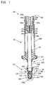
Fig. 1 is a partially cross sectional view schematically illustrating an internal structure of a temperature sensor according to an embodiment of the present invention; -
Fig. 2 is an enlarged longitudinal cross sectional view of a portion of the temperature sensor circled by A illustrated inFig. 1 ; -
Fig. 3 is a cross sectional view taken on line B-B inFig. 2 ; -
Fig. 4A is a view schematically demonstrating an insulator filling process according to the embodiment; -
Fig. 4B is a view schematically illustrating a slurry insulator filled in a metallic cover illustrated inFig. 1 at the completion of the insulator filling process according to the embodiment; -
Fig. 5A is a view schematically demonstrating a press fitting process according to the embodiment; -
Fig. 5B is a view schematically illustrating a sheathedwiring member 130 installed in the metallic cover at the completion of the press fitting process according to the embodiment; -
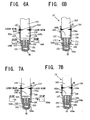
Fig. 6A is a view schematically demonstrating a crimping process according to the embodiment; -
Fig. 6B is a view schematically illustrating a thermal sensitive head illustrated inFig. 1 at the completion of the crimping process according to the embodiment; -
Fig. 7A is a view schematically demonstrating a crimping process according to a modification of the embodiment; and -
Fig. 7B is a view schematically illustrating the thermal sensitive head at the completion of the crimping process according to the modification of the embodiment. - An embodiment of the present invention will be described hereinafter with reference to the accompanying drawings.
- Referring to
Fig. 1 , there is provided atemperature sensor 100 applied to measure the temperature of exhaust gas discharged from an engine for vehicles. - The
temperature sensor 100 consists essentially of a lengthytemperature sensing member 5 and a substantiallycylindrical housing 20 for supporting and protecting thetemperature sensing member 5. - The
housing 20 is generally formed of aholder 201 having a lengthy opening therethrough, and a substantially annularmetallic tube 202 one end of which is fixedly joined to one opposing end of theholder 201 by being crimped and/or welded thereto. This allows the opening and the inner hollow portion of thetube 202 to communicate with each other. - The
temperature sensing member 5 is so disposed in the opening of theholder 201 and thetube 202 as to be aligned with the center of the housing 20 (holder 201 and the tube 202). One end portion of thetemperature sensing member 5 projects from the other end of theholder 201. - The
temperature sensing member 5 is provided at the tip end of its overhanging portion with a thermalsensitive head 10. Thetemperature sensing member 5 is also provided with a sheathedwiring member 130 coupled to the thermalsensitive head 10. - The
temperature sensor 100 is arranged such that the thermalsensitive head 10 is located in a passage through which the exhaust gas discharged from the engine flows. The passage is formed inside of, for instance, a catalytic converter for an exhaust emission control system of the engine or an exhaust pipe thereof. - Referring to
Fig. 2 , the thermalsensitive head 10 consists of athermistor 101, a pair ofelectrode wires 102, ametallic cover 104, and anelectric insulator 107. - The
thermistor 101 is used as an example of thermal sensitive elements. Thethermistor 101 is, for example, a thermally sensitive resistor whose resistance varies as the temperature changes. - The pair of
electrode wires 102 is made of, for example, platinum. One ends of the pair ofelectrode wires 102 are mounted in thethermistor 101 such that the remaining portions thereof are opposite to each other with a predetermined interval therebetween. - The sheathed
wiring member 130 is composed of a pair ofcore wires 103 and a substantially cylindrical pin or post likesheath 105. Each of thecore wires 103 is made of, for example, stainless steel, and has a substantially circular shape in its lateral cross section. Thecore wires 103 are covered with thesheath 105 by which they are electrically insulated. - One end of one of the
core wires 103 projecting from afirst edge surface 105a of oneend portion 105b of thesheath 105 is connected with one of the pair ofelectrode wires 102. Similarly, one end of the other of thecore wires 103 projecting from thefirst edge surface 105a of the oneend portion 105b of thesheath 105 is connected with the other of the pair ofelectrode wires 102. For example, the one ends of thecore wires 103 and theelectrode wires 102 are joined to each other by laser welding or resistance welding. - The
metallic cover 104 is configured to completely cover thethermistor 101, the pair ofelectrode wires 102, the pair ofcore wires 103, and the oneend portion 105b of thesheath 105 so as to protect them. - For example, a stainless steel plate is prepared, and deep drawing is applied to the stainless steel plate so that the
metallic cover 104 having an inner hollow cylindrical shape with one closed end CE is formed. - The
metallic cover 104 has a three-stepped cylindrical shape. Specifically, themetallic cover 104 has a firstcylindrical step wall 104a with the closed end CE, and a secondcylindrical step wall 104b continuing therefrom and having inward recesses 111. - The
inward recesses 111 are arranged opposite to each other. Each of theinward recesses 111 has a substantially semicircle shape in a cross section in parallel to the axial direction of thecover 104. Each of theinward recesses 111 has a height determined such that an inner surface thereof is in non-contact with thecore wires 103. - The
metallic cover 104 has a thirdcylindrical step wall 104c continuing from the secondcylindrical step wall 104b and having a diameter longer than the that of the secondcylindrical step wall 104b. - For example, the
thermistor 101 has a plate-like shape, and is made of, for instance, sinter-formed Cr(Chromium)-Mn(Manganese) based semiconductor materials. Thethermistor 101 is so installed in the firstcylindrical step wall 104a as to be arranged at the center thereof. The diameter of the firstcylindrical step wall 104a is determined to be as small as possible within the limits in which thethermistor 101 is separated from the inner circumference of the firstcylindrical step wall 104a. - Because the
thermistor 101 is located as close as possible to the inner circumference of the firstcylindrical step wall 104a, heat loss during heat transfer between themetallic cover 104 and thethermistor 101 is reduced. - The
metallic cover 104, that is, the thirdcylindrical step wall 104c has one open end OE opposite the closed end CE. The oneend portion 105b of the sheathedwiring member 130 is pressed into the thirdcylindrical step wall 104c via the open end OE with apredetermined clearance 109 therebetween. The outer periphery of thefirst edge surface 105a of thesheath 105 is fitted in the inner peripheral surface of a connection wall CW continuously connecting between the secondcylindrical step wall 104b and the thirdcylindrical step wall 104c. - At the open end side of the
metallic cover 104, an annular welded joint 110 is formed to fixedly couple thecylindrical step wall 104c and the oneend portion 105b of thesheath 105. - The
electric insulator 107 is made of, for example, alumina, and filled within astorage space 106 defined by the inner circumference of the metallic cover 104 (first and secondcylindrical step walls first edge surface 105a of thesheath 105. - Referring to
Fig. 3 , thesheath 105 is composed of a substantially cylindricalmetallic tube 108a longitudinally extending around the pair ofcore wires 103, and a composite compact 108b filled in the space between the inner wall surface of thetube 108a and the pair ofcore wires 103. The other ends of the pair ofcore wires 103 project from asecond edge surface 105c of thesheath 105 opposite thefirst edge surface 105a. - The composite compact 108b is formed by:
- inserting electrically insulating material powders, such as magnesia powders, into the inner space of the
tube 108a around each of the pair ofcore wires 103; and - subjecting the
tube 108a in which the magnesia powders are filed to drawing, thereby forming the composite compact 108b between the inner wall surface of thetube 108a and each of thecore wires 103. - With the configuration of the
sheath 105, the first andsecond edge surfaces sheath 105 around eachcore wire 103 are closed; this prevents foreign particles, such as hydrocarbons (HC) and/or carbon monoxides (CO), contained in the exhaust gas from entering into the interior of thesheath 105. - The sheathed
wiring member 130 is disposed in the opening of theholder 201 and thetube 202 such that the oneend portion 105b of thesheath 105 projects from theholder 201. - The
temperature sensor 100 further consists of a pair ofterminals 150, arubber bush 152, and awiring cable 203. Thewiring cable 203 is composed of a pair ofleads 203a and a substantiallycylindrical sheath 203b with which theleads 203a are covered to be electrically insulated. - The
rubber bush 152 is so inserted in one end of thesheath 203b as to be mounted on the inner circumference of the one end of thesheath 203b. One ends of the pair ofleads 203a are connected with a control circuit, such as an electronic control unit (ECU) (not shown). - The other end of the
tube 202 opposite the holder side end thereof is formed as aconnector 202a, and the one end of thesheath 203b is formed as aconnector 203c. Specifically, theconnector 203c of thesheath 203b is pressed to be fitted into theconnector 202a of thetube 202 so that theconnector 203c is airtightly engaged with theconnector 202a. - One ends of the pair of
terminals 150 are connected with the other ends of the pair ofcore wires 103 projecting from thesecond edge surface 105c of thesheath 105. - The paired
terminals 150 are so disposed within thetube 202 as to be close to theconnector 202a. Specifically, when thewiring cable 203 and thetube 202 of thetemperature sensor 100 are joined to each other by the engagement of theirconnectors leads 203a are connected with the pair ofterminals 150. This establishes electrical connection between thethermistor 101 and the control circuit via theelectrode wires 102, thecore wires 103, theterminals 150, and theleads 203a. - The joint portions between the pair of
lead wires 203a and the pair ofcore wires 103 via the pair ofterminals 150 are each covered with aresin tube 205 made of, for example, a heat-resistant resin. Theresin tube 205 works to protect the joint portions. - Next, schematic operations of the
temperature sensor 100 will be described hereinafter. - While exhaust gas discharged from the engine flows through the passage formed inside of the catalytic converter or the exhaust pipe, heat is received by the
metallic cover 104, and the received heat is transferred via theelectric insulator 107 to thethermistor 101. This allows the temperature of thethermistor 101 to change so that the resistance of thethermistor 101 is changed. The change in the resistance of thethermistor 101 is measured thereby as an electric signal, and the electric signal is sent to the control circuit via theelectrode wires 102 and thecore wires 103. This permits the control circuit to measure the temperature of the exhaust gas based on the electric signal sent from thethermistor 101. - Next, a method of manufacturing the
temperature sensor 100 will be described hereinafter. - First, in an insulator filling process, the
metallic cover 104, which has been produced using a stainless steel set forth above, and a dispenser with aneedle 300 are prepared. The dispenser is designed to contain alumina in an aqueous slurry as theelectric insulator 107 and to feed, from theneedle 300, the contained alumina into themetallic cover 104 through the open end OE thereof. Note that the slurry alumina (slurry insulator 107) to be sprayed from theneedle 300 is for instance formed by adding, to alumina, pure water and dispersant to modify the viscosity of the mixture of the alumina and pure water (seeFigs. 4A and 4B ). In place of the alumina, silica, magnesia, or another material can be used. - The amount of the slurry alumina to be supplied from the dispenser into the
metallic cover 104 is determined as follows. - A target volume V to be supplied from the dispenser into the
metallic cover 104 is expressed by the following equation [1]:
where ΔV represents a tolerance (± ΔV) for the target volume V, v1 represents a design volume of thestorage space 106, and Δ v1 represents a design tolerance ( ± Δ v1 ) for the design volume v1 of thestorage space 106. During the design stages, determination of the design volume v1 allows determination of the design tolerance ± Δ v1, and similarly, determination of the target volume V allows determination of the tolerance (± Δ V). - Note that the tolerance (± Δ V) depends on the supply facility capacity of the dispenser, and therefore the design tolerance (± Δ v1) is constantly lower than the tolerance (± Δ V). This can establish the following inequality [2]:

- The design volume v1 of the
storage space 106 is determined by subtracting a design volume of each of thethermistor 101, theelectrode wires 102, and the projectingcore wires 103 from the volume of a space; this space is defined by the inner circumference of themetallic cover 104 and thefirst edge surface 105a of thesheath 105 assuming that none of thethermistor 101, theelectrode wires 102, and the projectingcore wires 103 are installed in thestorage space 106. - When the slurry alumina with the target volume V is sprayed from the
needle 300 of the dispenser, the amount of the slurry alumina to be actually fed into themetallic cover 104 is represented as "X". The amount X of actually supplied slurry alumina meets the following inequality [3]
- The establishment of the inequality [2] allows the following inequality [4] to be established:

- Referring to
Fig. 5A , theelectrode wires 102 of the sheathedmember 130 mounted in thethermistor 101 are respectively joined to the one ends of the pair ofcore wires 103 by laser welding or resistance welding. - After the completion of the insulator filling process, the sheathed
wiring member 130 integrated with thethermistor 101 is inserted, from its thermistor side, into the slurry-alumina filledmetallic cover 104 such that thethermistor 101, theelectrode wires 102, and thecore wires 103 are kept noncontact with the inner circumference of themetallic cover 104. - Thereafter, when the one
end portion 105b of the sheathedwiring member 130 of the is close to the open end OE of themetallic cover 104, the oneend portion 105b of the sheathedwiring member 130 is pressed into themetallic cover 104 from the open end OE toward the closed end CE thereof (seeFig. 5B ). The press fitting is carried out until the outer periphery of thefirst edge surface 105a of thesheath 105 is fitted in the inner peripheral surface of the connection wall CW continuously connecting between the secondcylindrical step wall 104b and the thirdcylindrical step wall 104c. - The outer periphery of the
first edge surface 105a of thesheath 105 fitted in the inner peripheral surface of the connection wall CW of themetallic cover 104 provides thestorage space 106 defined between thefirst edge surface 105a of thesheath 105 and the inner circumference of themetallic cover 104. - At the time of the completion of the press fitting of the sheathed
wiring member 130 in themetallic cover 104, a substantial volume Y of thestorage space 106 is determined by subtracting the volume of each of thethermistor 101, theelectrode wires 102, and thecore wires 103 from the volume of a space; this space is defined by the inner circumference of themetallic cover 104 and thefirst edge surface 105a of thesheath 105 assuming that none of thethermistor 101, theelectrode wires 102, and thecore wires 103 are installed in thestorage space 106. - In producing the
temperature sensor 100 in volume, sensor-to-sensor vibration in the volume of thethermistor 101, the protectingcover 104, and/or the sheathedwiring member 130 occur. In particular, the sensor-to-sensor vibration in the volume of the protectingcover 104, and/or the sheathedwiring member 130 causes sensor-to-sensor vibration in the position of thefirst edge surface 105a of thesheath 105. The sensor-to-sensor vibrations set forth above causes sensor-to-sensor vibration in the volume Y of thestorage space 106. Note that the volume Y of thestorage space 106 meets the following inequality [5]:
- As described above, because the inequality [4] is constantly established, the amount X of actually supplied slurry alumina into the
metallic cover 104 is equal to or lower than the volume "v1 - Δv1". For this reason, the outer periphery of thefirst edge surface 105a of thesheath 105 fitted in the inner peripheral surface of the connection wall CW of themetallic cover 104 provides a given length L is provided between thefirst edge surface 105a and a fluid level of the slurry alumina contained in themetallic cover 104. Note that the length L may be zero. - The given length L ensured between the
first edge surface 105a and the fluid level of the slurry alumina contained in themetallic cover 104 prevents the slurry alumina from rising into theclearance 109 during the press fitting of the sheathedwiring member 130 in themetallic cover 104. This prevents poor weld between thecylindrical step wall 104c and the oneend portion 105b of thesheath 105 due to part of the slurry alumina lying in theclearance 109. - After the completion of the press fitting process, an intermediate product integrated with the
thermistor 101, the sheathedwiring member 130, and themetallic cover 104 is dried at a high temperature. The drying process evaporates water contained in the slurry alumina filled within thestorage space 106; this results that the contained slurry alumina is dried to become a powder alumina (powder insulator 107). - Next, as illustrated in
Fig. 6A , a laser beam is irradiated to an annular part of the outer circumference of the thirdcylindrical step wall 104c at the open end side thereof so as to form an annular welded joint 110. The annular welded joint 110 fixedly couples thecylindrical step wall 104c and the oneend portion 105b of thesheath 105. Another method, such as plasma welding or crimping can be used to more fixedly join thecylindrical step wall 104c and the oneend portion 105b of thesheath 105. - In addition, as illustrated in
Figs. 6A and 6B , a swaging tool is prepared. For example, the swaging tool has a pair of dies 400 each has a substantially rectangular surface. The dies 400 are arranged such that the rectangular surfaces are located on either side of the outer circumference of the secondcylindrical step wall 104b radially adjacent to thehead 105c of thesheath 105 across theclearance 109. - The swaging tool works to inwardly move the dies 400 to locally crimp, by the rectangular surfaces, the outer circumference of the second
cylindrical step wall 104b. This reduces the diameter of part of the outer circumference of the oneend portion 105b of thesheath 105 to thereby form theinward recesses 111 in the oneend portion 105b thereof. - When the reduction in volume of the
storage space 106 by theinward recesses 111 is referred to as "a", it is determined such that the following equation [6] is constantly established:
- Because the tolerances Δ V and Δ v1 are always constant, the reduction "a" in volume of the
storage space 106 becomes always constant. - For this reason, even if the amount X of actually supplied slurry alumina into the
metallic cover 104 and the volume Y of thestorage space 106 are changed within the respective tolerances ± Δ V and Δ v1 individually in producing thetemperature sensor 100 in volume, it is possible to fully fill the slurry alumina within thestorage space 106 each of the mass producedtemperature sensors 100. - Note that the
powder insulator 107 being fully filled within thestorage space 106 means that the interface of thepowder insulator 107 is uniformly in contact with thefirst edge surface 105a of the sheath 105 (seeFig. 7B ). - In the embodiment, the
temperature sensor 100 is designed such that the ratio of the design volume v1 of thestorage space 106 to the reduction "a" in volume of thestorage space 106 is 1:0.2 (1/0.2=5). In other words, thetemperature sensor 100 is designed so as to meet the following equation [7]:
- To more secure resistance against vibration, the
temperature sensor 100 is preferably designed such that a percentage of the reduction "a" in volume of thestorage space 106 be within the range from 10 % to 40 %. In other words, thetemperature sensor 100 is preferably designed such that the design volume v1 meet the following equation [8]:
- Thereafter, the powder alumina contained in the
storage space 106 is fired by heating to thereby form theinsulator 107 within thestorage space 106. This results that the thermalsensitive head 10 is completed. - For example, after the process of producing the thermal
sensitive head 10, as set forth above, thewiring cable 203 and thetube 202 of thetemperature sensor 100 are joined to each other by the engagement of theirconnectors core wires 103 to be connected with theleads 203a of the wiring cable 230 via theterminals 150, and the joint portions between thelead wires 203a and thecore wires 103 via theterminals 150 are each covered with theresin tube 205. - This results that the
temperature sensor 100 illustrated inFig. 1 is completed. - As described above, the
thermistor sensor 100 is provided with theinsulator 107 filled thoroughly within thestorage space 106 defined by thefirst edge surface 105a of thesheath 105 and the inner circumference of the first and secondcylindrical step walls metallic cover 104. - The
insulator 107 is formed by: - feeding alumina in slurry into the
metallic cover 104 to fill it therewithin; - inserting the sheathed
wiring member 130 into themetallic cover 104; - pressing the one
end portion 105b of the sheathedwiring member 130 into themetallic cover 104 so that thefirst edge surface 105a of thesheath 105 is fitted in the inner peripheral surface of the connection wall CW continuously connecting between the secondcylindrical step wall 104b and the thirdcylindrical step wall 104c; - deforming inwardly part of the outer circumference of the one
end portion 105b of thesheath 105 to form theinward recesses 111 in the oneend portion 105b thereof; theseinward recesses 111 reduce the volume of thestorage space 106 to thereby fully fill the alumina in powder within thestorage space 106; and - firing the alumina in powder filled within the
storage space 106. - Thus, in producing the
temperature sensor 100 in volume, even if sensor-to-sensor variation in the rate of insulator feeding occurs, the alumina in powder filled thoroughly within thestorage space 106 allows no cavities in theelectric insulator 107. - This prevents the
thermistor 101, theelectrode wires 102, and thecore wires 103 from vibrating at individually different frequencies even if thetemperature sensor 100 is vibrated. In other words, this allows the vibration of each of thethermistor 101, theelectrode wires 102, and thecore wires 103 to synchronize with that of the whole of the thermalsensitive head 10 even if thetemperature sensor 100 is vibrated. Accordingly, makes it possible to avoid: - the concentration of stress on the joint portions between the
electrode wires 102 and thecore wires 103; and - the failure of the
thermistor 101 due to physical factors. - The
temperature sensor 100 is preferably designed such that the reduction "a" in volume of thestorage space 106 be within the range from 10 % to 40 %. - If the reduction "a" in volume of the
storage space 106 were lower than 10 %, the packing density of theinsulator 107 in thestorage space 106 may become insufficient; this result has been demonstrated by the inventor's experiments. - If the reduction "a" in volume of the
storage space 106 were higher than 40 %, the inward deformation of themetallic cover 104 may adversely affect some components of the thermalsensitive head 10 located within thestorage space 106; this result has been demonstrated by the inventor's experiments. For example, the reduction "a" in volume of thestorage space 106 were higher than 40 %, the inward deformation of themetallic cover 104 may adversely affect theelectrode wires 102 or thethermistor 101. - However, as set forth above, when the reduction "a" in volume of the
storage space 106 is within the range from 10 % to 40 %, it is possible to more reliably avoid the development of the problems set forth above. - In the method of manufacturing the
temperature sensor 100, the number of theinward recesses 111 can be freely determined as long as the reduction "a" in volume of thestorage space 106 meets the equation [6] and excessive stress is not applied to thethermistor 101, theelectrode wires 102, and thecore wires 103. The circumferential length of each of theinward recesses 111 can also be freely determined as long as the reduction "a" in volume of thestorage space 106 meets the equation [6] and excessive stress is not applied to thethermistor 101, theelectrode wires 102, and thecore wires 103. - In the embodiment, a volume Y' of the
storage space 106 after deformation may become lower than the amount X actually supplied slurry alumina into themetallic cover 104. In this case, theinsulator 107 in powder is merely compressed with little effect on thethermistor 101, theelectrode wires 102, and thecore wires 103. Instead, the compression of theinsulator 107 in powder allows the packing density thereof in thestorage space 106 to increase, making it possible to more improve the protection ability of the insulator 7 with respect to thethermistor 101. - In the embodiment, as described above, the
metallic cover 104 has a three-stepped cylindrical shape. The structure allows thethermistor 101 to be located as close as possible to the inner circumference of the firstcylindrical step wall 104a via theinsulator 107, making it possible to reduce heat loss during heat transfer between themetallic cover 104 and thethermistor 101. - Thus, in a modification of the embodiment, in the crimping process, a swaging tool is prepared. For example, the swaging tool has a pair of dies 400a each has a substantially semicylindrical surface. The dies 400a are arranged such that the semicylindrical surfaces are located on either side of the outer circumference of the second
cylindrical step wall 104b. - The swaging tool works to move the dies 400a towards each other to uniformly crimp, by the semicylindrical surfaces, the outer circumference of the outer circumference of the second
cylindrical step wall 104b (Fig. 7A ). This uniformly reduces the diameter of the outer circumference of the secondcylindrical step wall 104b, thus reducing the volume of the storage space 106 (seeFig. 7B ). - In the modification, the reduction in volume of the
storage space 106 meets the equation [6] as well as the embodiment. - While there has been described what is at present considered to be the embodiment and its modifications of the present invention, it will be understood that various modifications which are not described yet may be made therein, and it is intended to cover in the appended claims all such modifications as fall within the true spirit and scope of the invention.
- In a method of manufacturing a temperature sensor, a temperature sensing member is inserted into a cover from a thermal sensitive head via an open end thereof until an edge surface of one end portion of a lengthy sheath is in contact with a middle portion of an inner wall surface of a tubular wall of the cover in a longitudinal direction thereof so that a storage space is formed between the inner wall surface and the edge surface. The thermal sensitive head is stored in the storage space and covered with the tubular wall. The one end portion of the lengthy sheath is fixed to the inner wall surface of the tubular wall of the cover. The tubular wall of the cover is inwardly deformed to reduce a volume of the storage space, thus fully filling the insulator within the storage space.
Claims (6)
- A temperature sensor comprising:a thermal sensitive element having a pair of electrodes coupled thereto;a sheathed wiring member comprising: a pair of wires each with one end; and a lengthy sheath having one end portion and covering the pair of wires such that the one end of each of the wires overhangs from an edge surface of the one end portion of the lengthy sheath, the one end of each of the wires being connected with a corresponding one of the electrodes;a cover having a tubular wall with a closed end and an open end opposite thereto, the one end portion of the lengthy sheath being inserted in the cover via the open end thereof, an inner wall surface of the tubular wall of the cover and the edge surface of the one end portion of the lengthy sheath providing a storage space therebetween, the thermal sensitive element, the pair of electrodes, and the one end of each of the wires being stored in the storage space and covered with the tubular wall, at least part of an outer surface of the tubular wall being formed with an inward recess, the inward recess being located between the edge surface of the one end portion of the lengthy sheath and the electrodes; andan electric insulator filled thoroughly within the storage space.
- A method of manufacturing a temperature sensor, the method comprising:preparing a temperature sensing member, the temperature sensing member comprising: a thermal sensitive element having a pair of electrodes coupled thereto; and a sheathed wiring member, the sheathed wiring member comprising: a pair of wires each with one end; and a lengthy sheath having one end portion and covering the pair of wires such that the one end of each of the wires overhangs from an edge surface of the one end portion of the lengthy sheath, the one end of each of the wires being connected with a corresponding one of the electrodes;preparing a cover having a lengthy tubular wall with a closed end and an open end opposite thereto;feeding a predetermined volume of an insulator into the cover so that the insulator is filled in the cover;inserting the temperature sensing member into the cover from the thermal sensitive element via the open end thereof until the edge surface of the one end portion of the lengthy sheath is in contact with a middle portion of an inner wall surface of the tubular wall of the cover in a longitudinal direction thereof so that a storage space is formed between the inner wall surface of the tubular wall of the cover and the edge surface of the one end portion of the lengthy sheath, the thermal sensitive element, the pair of electrodes, and the one end of each of the wires being stored in the storage space and covered with the tubular wall;fixing the one end portion of the lengthy sheath to the inner wall surface of the tubular wall of the cover; andinwardly deforming the tubular wall of the cover to reduce a volume of the storage space, thus fully filling the insulator within the storage space.
- A method of manufacturing a temperature sensor according to claim 2, wherein the inwardly deforming step crimps an outer wall surface of the tubular wall of the cover to form at least one inward recess in the outer wall surface of the tubular wall of the cover.
- A method of manufacturing a temperature sensor according to claim 2 or 3, wherein a percentage of reduction the storage space in volume by the inwardly deforming is set within a range from 10 % to 40%.
- A method of manufacturing a temperature sensor according to any one of claims 2-4, wherein the fixing step fits the one end portion of the lengthy sheath into the tubular wall of the cover such that the insulator filled in the cover is in noncontact with the edge surface of the one end portion of the length sheath.
- A method of manufacturing a temperature sensor according to any one of claims 2-5, wherein the predetermined volume of the insulator to be filled in the cover is lower than a volume obtained by subtracting a design tolerance (Δv1) from a design volume (v1) of the storage space.
Applications Claiming Priority (1)
| Application Number | Priority Date | Filing Date | Title |
|---|---|---|---|
| JP2007097711A JP2008256471A (en) | 2007-04-03 | 2007-04-03 | Manufacturing method of temperature sensor |
Publications (2)
| Publication Number | Publication Date |
|---|---|
| EP1978340A2 true EP1978340A2 (en) | 2008-10-08 |
| EP1978340A3 EP1978340A3 (en) | 2008-10-22 |
Family
ID=39642655
Family Applications (1)
| Application Number | Title | Priority Date | Filing Date |
|---|---|---|---|
| EP08153964A Withdrawn EP1978340A3 (en) | 2007-04-03 | 2008-04-02 | Temperature sensor with improved resistance against vibration |
Country Status (2)
| Country | Link |
|---|---|
| EP (1) | EP1978340A3 (en) |
| JP (1) | JP2008256471A (en) |
Cited By (3)
| Publication number | Priority date | Publication date | Assignee | Title |
|---|---|---|---|---|
| WO2011027053A1 (en) * | 2009-09-07 | 2011-03-10 | Sc2N | Temperature sensor, in particular for sensing the temperature of gas in a combustion engine, and associated manufacturing method |
| DE102009045811A1 (en) * | 2009-10-19 | 2011-04-21 | Endress + Hauser Flowtec Ag | Sensor for thermal flow rate measuring device, has cable electrically contacting resistance thermometer and passed through opened end of case, where case is partially filled with composite material that is utilized as filling material |
| DE102012109312A1 (en) * | 2012-10-01 | 2014-04-03 | Endress + Hauser Flowtec Ag | Temperature sensor and flowmeter |
Families Citing this family (2)
| Publication number | Priority date | Publication date | Assignee | Title |
|---|---|---|---|---|
| JP5268874B2 (en) * | 2009-12-07 | 2013-08-21 | 日本特殊陶業株式会社 | Temperature sensor |
| JP7044675B2 (en) * | 2018-09-14 | 2022-03-30 | 日本特殊陶業株式会社 | Manufacturing method of temperature sensor |
Citations (2)
| Publication number | Priority date | Publication date | Assignee | Title |
|---|---|---|---|---|
| US20060013282A1 (en) | 2004-07-16 | 2006-01-19 | Ngk Spark Plug Co., Ltd. | Temperature sensor and method for producing the same |
| US7060949B1 (en) | 2003-05-16 | 2006-06-13 | Watlow Electric Manufacturing Company | End seal design for temperature sensing probes |
-
2007
- 2007-04-03 JP JP2007097711A patent/JP2008256471A/en active Pending
-
2008
- 2008-04-02 EP EP08153964A patent/EP1978340A3/en not_active Withdrawn
Patent Citations (2)
| Publication number | Priority date | Publication date | Assignee | Title |
|---|---|---|---|---|
| US7060949B1 (en) | 2003-05-16 | 2006-06-13 | Watlow Electric Manufacturing Company | End seal design for temperature sensing probes |
| US20060013282A1 (en) | 2004-07-16 | 2006-01-19 | Ngk Spark Plug Co., Ltd. | Temperature sensor and method for producing the same |
Cited By (4)
| Publication number | Priority date | Publication date | Assignee | Title |
|---|---|---|---|---|
| WO2011027053A1 (en) * | 2009-09-07 | 2011-03-10 | Sc2N | Temperature sensor, in particular for sensing the temperature of gas in a combustion engine, and associated manufacturing method |
| FR2949857A1 (en) * | 2009-09-07 | 2011-03-11 | Sc2N Sa | TEMPERATURE SENSOR, IN PARTICULAR FOR GAS TEMPERATURE TAKING IN A COMBUSTION ENGINE AND METHOD OF MANUFACTURING THE SAME |
| DE102009045811A1 (en) * | 2009-10-19 | 2011-04-21 | Endress + Hauser Flowtec Ag | Sensor for thermal flow rate measuring device, has cable electrically contacting resistance thermometer and passed through opened end of case, where case is partially filled with composite material that is utilized as filling material |
| DE102012109312A1 (en) * | 2012-10-01 | 2014-04-03 | Endress + Hauser Flowtec Ag | Temperature sensor and flowmeter |
Also Published As
| Publication number | Publication date |
|---|---|
| EP1978340A3 (en) | 2008-10-22 |
| JP2008256471A (en) | 2008-10-23 |
Similar Documents
| Publication | Publication Date | Title |
|---|---|---|
| US7104685B2 (en) | Temperature sensor with quick response | |
| US10076002B2 (en) | Electric cartridge type heater and method for manufacturing same | |
| CN101268308B (en) | Composite conductor, in particular for heater plugs of a diesel engine | |
| US6899457B2 (en) | Thermistor temperature sensor | |
| US7553078B2 (en) | Temperature sensor and method for producing the same | |
| EP2406606B1 (en) | Sensor lead sealing and strain relief | |
| EP1978340A2 (en) | Temperature sensor with improved resistance against vibration | |
| US9596795B2 (en) | Manufacturing method for sensor of a thermal flow measuring device | |
| EP2068137A2 (en) | Temperature sensor | |
| CN102216603A (en) | Glow plug with metallic heater probe | |
| US6759796B2 (en) | Compact spark plug and method for its production | |
| CN108204863A (en) | High-temperature exhaust air sensor | |
| US20180235032A1 (en) | Electrical device with tubular metal sheathing and insulating element held therein | |
| CN108426649A (en) | Cartridge heater with temperature sensor | |
| EP2701459B1 (en) | Ceramic heater and manufacturing method thereof | |
| EP1975580A2 (en) | Temperature sensor with improved resistance against vibration | |
| JP4317191B2 (en) | Measuring sensor | |
| US10302507B2 (en) | Temperature sensor and method for manufacturing the same | |
| JP2007309674A (en) | Temperature sensor | |
| JP5123344B2 (en) | Temperature sensor | |
| JP2017223556A (en) | Temperature sensor | |
| JP7045161B2 (en) | Glow plug | |
| JP6825919B2 (en) | Temperature sensor | |
| CN110715751A (en) | Temperature sensor |
Legal Events
| Date | Code | Title | Description |
|---|---|---|---|
| PUAI | Public reference made under article 153(3) epc to a published international application that has entered the european phase |
Free format text: ORIGINAL CODE: 0009012 |
|
| PUAL | Search report despatched |
Free format text: ORIGINAL CODE: 0009013 |
|
| AK | Designated contracting states |
Kind code of ref document: A2 Designated state(s): AT BE BG CH CY CZ DE DK EE ES FI FR GB GR HR HU IE IS IT LI LT LU LV MC MT NL NO PL PT RO SE SI SK TR |
|
| AX | Request for extension of the european patent |
Extension state: AL BA MK RS |
|
| AK | Designated contracting states |
Kind code of ref document: A3 Designated state(s): AT BE BG CH CY CZ DE DK EE ES FI FR GB GR HR HU IE IS IT LI LT LU LV MC MT NL NO PL PT RO SE SI SK TR |
|
| AX | Request for extension of the european patent |
Extension state: AL BA MK RS |
|
| 17P | Request for examination filed |
Effective date: 20090422 |
|
| AKX | Designation fees paid |
Designated state(s): DE FR |
|
| STAA | Information on the status of an ep patent application or granted ep patent |
Free format text: STATUS: THE APPLICATION HAS BEEN WITHDRAWN |
|
| 18W | Application withdrawn |
Effective date: 20090907 |