EP1978260A1 - Centrifugal drainage pump - Google Patents
Centrifugal drainage pump Download PDFInfo
- Publication number
- EP1978260A1 EP1978260A1 EP06742012A EP06742012A EP1978260A1 EP 1978260 A1 EP1978260 A1 EP 1978260A1 EP 06742012 A EP06742012 A EP 06742012A EP 06742012 A EP06742012 A EP 06742012A EP 1978260 A1 EP1978260 A1 EP 1978260A1
- Authority
- EP
- European Patent Office
- Prior art keywords
- rib
- shaft sleeve
- impeller
- notch
- starting
- Prior art date
- Legal status (The legal status is an assumption and is not a legal conclusion. Google has not performed a legal analysis and makes no representation as to the accuracy of the status listed.)
- Granted
Links
Images

Classifications
-
- F—MECHANICAL ENGINEERING; LIGHTING; HEATING; WEAPONS; BLASTING
- F16—ENGINEERING ELEMENTS AND UNITS; GENERAL MEASURES FOR PRODUCING AND MAINTAINING EFFECTIVE FUNCTIONING OF MACHINES OR INSTALLATIONS; THERMAL INSULATION IN GENERAL
- F16F—SPRINGS; SHOCK-ABSORBERS; MEANS FOR DAMPING VIBRATION
- F16F15/00—Suppression of vibrations in systems; Means or arrangements for avoiding or reducing out-of-balance forces, e.g. due to motion
- F16F15/10—Suppression of vibrations in rotating systems by making use of members moving with the system
- F16F15/12—Suppression of vibrations in rotating systems by making use of members moving with the system using elastic members or friction-damping members, e.g. between a rotating shaft and a gyratory mass mounted thereon
- F16F15/121—Suppression of vibrations in rotating systems by making use of members moving with the system using elastic members or friction-damping members, e.g. between a rotating shaft and a gyratory mass mounted thereon using springs as elastic members, e.g. metallic springs
- F16F15/124—Elastomeric springs
- F16F15/1245—Elastic elements arranged between substantially-radial walls of two parts rotatable with respect to each other, e.g. between engaging teeth
-
- F—MECHANICAL ENGINEERING; LIGHTING; HEATING; WEAPONS; BLASTING
- F04—POSITIVE - DISPLACEMENT MACHINES FOR LIQUIDS; PUMPS FOR LIQUIDS OR ELASTIC FLUIDS
- F04D—NON-POSITIVE-DISPLACEMENT PUMPS
- F04D13/00—Pumping installations or systems
- F04D13/02—Units comprising pumps and their driving means
- F04D13/021—Units comprising pumps and their driving means containing a coupling
-
- F—MECHANICAL ENGINEERING; LIGHTING; HEATING; WEAPONS; BLASTING
- F04—POSITIVE - DISPLACEMENT MACHINES FOR LIQUIDS; PUMPS FOR LIQUIDS OR ELASTIC FLUIDS
- F04D—NON-POSITIVE-DISPLACEMENT PUMPS
- F04D13/00—Pumping installations or systems
- F04D13/02—Units comprising pumps and their driving means
- F04D13/06—Units comprising pumps and their driving means the pump being electrically driven
- F04D13/0606—Canned motor pumps
Definitions
- the present invention relates in general to a centrifugal drainage pump, particularly being used in household electrical appliances and the like.
- a centrifugal drainage pump of that type is described in a US patent with the application number of 10/723295 and the publication number of US2005/0111992 .
- the pump illustrated in this patent was designed to solve the problem of that its motor was easily burned out owing to heavy load during initial start-up of the pump.
- the major contribution of the invention is to improve the start-up coupling between a shaft sleeve and an impeller.
- a starting rib is set up on the shaft sleeve, and a stopping rib inside of the impeller extrudes inwardly.
- the starting rib and stopping rib each have two side faces radiating in axial direction which are wrapped with a layer of resilient materials to reduce noise and absorb shock.
- such configuration is quite complicated and suffers from higher costs of manufacture and maintenance.
- the present invention provides, directing to the deficiency of the prior art, a centrifugal drainage pump with improved structure of the starting rib and the stopping rib of the centrifugal drainage pump.
- the present invention provides a centrifugal drainage pump, comprising a rotor chamber and a pump cover chamber which are separated from one another, wherein the said rotor chamber includes a pump body , a permanent magnet rotor , a rotor shaft, a bearing and a bearing seat; the said pump cover chamber includes a pump cover with a water-inlet, a shaft sleeve and an impeller provided with a holding chamber in its center for holding the shaft sleeve, the pump being characterized in that the shaft sleeve is provided with a tubular body, and a starting rib which is integral with the shaft sleeve extrudes outwardly form the tubular body ; the impeller is provided with a stopping rib projecting inwardly from the internal wall of the holding chamber, and the starting rib interferes with the stopping rib after it rotates in one direction or reversely for a certain distance; among pairs of interference contact surfaces between the starting rib and the stopping rib, at least one of each pair of interference
- two interference contact surfaces of the starting rib are attached with the shock absorbing pad; or two interference contact surfaces of the stopping rib are attached with the shock absorbing pad; or two interference contact surfaces of the starting rib and two interference contact surfaces of the stopping rib are attached with the shock absorbing pads.
- the shaft sleeve is in the shape of an upside down letter "T", the upper part of which is the tubular body in cylindrical shape and the lower part of which is an annular protruding platform.
- the upper part of the impeller is arranged with a rotor shaft holding chamber fitting with the rotor shaft which passes through the shaft sleeve and fits into the rotor shaft holding chamber.
- the present centrifugal drainage pump comprises a rotor chamber and a pump cover chamber which are mutually separated.
- the said rotor chamber consists of a pump body 11, a permanent magnet rotor 9, a rotor shaft 4, bearing 12 and a bearing seat.
- the said pump cover chamber consists of a pump cover 16 with a water-inlet, a shaft sleeve 3, an impeller 1 and an impeller washer 6.
- the annular impeller washer 6 locating below the holding chamber of the impeller 1 closes the holding chamber and keeps the shaft sleeve 3 stay inside of it.
- a starting rib 18 is extruded outwardly from surface of the body of the shaft sleeve, whereas a stopping rib 19 is extruded inwardly from internal surface of the holding chamber of the impeller. After turning forward or backwards for a certain distance, the starting rib 18 interferes with the stopping rib 19.
- the inventive point of the present invention rests in the start-up coupling between the shaft sleeve 3 and the impeller 1. Structure of the two components and its coupling will be described in detail.
- the said shaft sleeve 3 has a tubular body, in the bottom of which there is an annular protruding platform, so that it is in shape of upside down letter "T".
- a throughgoing hole 22 for holding the rotor shaft 4 is located in the center of the tubular body and the annular protruding platform.
- a starting rib 18 extruding radially and outwardly from the tubular body is moulded integratedly with the shaft sleeve 4.
- the outside surface of the starting rib is a cambered surface that is flush with the annular protruding platform.
- the left and right sides in radial direction of the said starting rib are straight flat surfaces.
- a notch 23 extending axially is recessed respectively on the both side surfaces.
- the open end of the notch is narrower than its inner space.
- Two shock absorbing pads 5 of the shaft sleeve are fitted onto the left and right side surfaces of the starting rib respectively, the outside of which is also a cambered surface that is flush with of the annular protruding platform, but the internal side of which fits surface of the tubular body.
- a strip of convex ridge 24 locates on the contacting surface of the shock absorbing pads 5 of the shaft sleeve attaching to the starting rib.
- the said convex ridge fits in the notch on the both side surfaces of the starting rib mutually.
- the convex ridge of shock absorbing pads 5 of the shaft sleeve can be inserted basipetally into the said notch 23 along its axial direction. Because the outside part of the notch is narrower than its inner space, the shock absorbing pads 5 of the shaft sleeve can not be separated from the notch in transverse direction, so that the shock absorbing pads 5 of the shaft sleeve can tightly contact with the side surfaces.
- Figs. 5 are the structure sketch and sectional view of the impeller.
- a cylindrical holding chamber 17 is arranged in the center of the impeller, and the diameter of the chamber 17 is equal to that of a protruding platform 21 of the shaft sleeve.
- a stopping rib 19 is extruded inwardly from the internal wall of the said holding chamber.
- the internal side of the said stopping rib 19 has a cambered surface fitted with the outside surface of the shaft sleeve body 20.
- the left and right sides of it has flat surfaces.
- a notch 25 extending axially is recessed on each of these two surfaces.
- the open-end of the notch is narrower than inner space of the notch.
- Two shock absorbing pads 2 of the impeller are fitting on the said two surfaces.
- the internal side of the shock absorbing pads of the impeller is a cambered surface fitted with the outside surface of the shaft sleeve body, but its outside is a cambered surface fitted with the internal wall of the shaft sleeve holding chamber.
- a convex ridge 26 extrudes from the surface of the shock absorbing pad of the impeller which is fitted with the stopping rib.
- the said convex ridge is coupled with the said notch 25 located on either side of the stopping rib so as to form a close contact structure as that of the said shock absorbing pads 5 of the shaft sleeve with the side surface of the starting rib.
- a rotor shaft holding chamber 28 is build on the top of the impeller, In which the rotor shaft fits.
- the rotor shaft passing through the shaft sleeve is plugged into the said rotor shaft holding chamber.
- the inventive point of the present invention focuses on the attaching structure of the shock absorbing pad.
- there are two pairs of interference contact surfaces between the starting rib and the stopping rib namely, the left side of the starting rib in the radial direction and the right side of the stopping rib in the radial direction form a pair of interference contact surfaces, whereas the right side of the starting rib in the radial direction and left side of the stopping rib in the radial direction form the other pair of interference contact surfaces.
- Either shock absorbing pads can absorb impact generated between each pair of interference contact surfaces.
- the above means to place the shock absorbing pad shall fall in the protection scope claimed in the present invention, no matter the shock absorbing pad is placed on the interference contact surfaces of the starting rib or on the interference contact surfaces of the stopping rib, or as it is disclosed in the present invention, on both of the interference contact surfaces of the starting rib and on both of the interference contact surfaces of the stopping rib.
Landscapes
- Engineering & Computer Science (AREA)
- General Engineering & Computer Science (AREA)
- Mechanical Engineering (AREA)
- Physics & Mathematics (AREA)
- Acoustics & Sound (AREA)
- Aviation & Aerospace Engineering (AREA)
- Structures Of Non-Positive Displacement Pumps (AREA)
Abstract
Description
- The present invention relates in general to a centrifugal drainage pump, particularly being used in household electrical appliances and the like.
- A centrifugal drainage pump of that type is described in a US patent with the application number of
10/723295 US2005/0111992 . The pump illustrated in this patent was designed to solve the problem of that its motor was easily burned out owing to heavy load during initial start-up of the pump. The major contribution of the invention is to improve the start-up coupling between a shaft sleeve and an impeller. As shown in attached figures of that patent, a starting rib is set up on the shaft sleeve, and a stopping rib inside of the impeller extrudes inwardly. The starting rib and stopping rib each have two side faces radiating in axial direction which are wrapped with a layer of resilient materials to reduce noise and absorb shock. However, such configuration is quite complicated and suffers from higher costs of manufacture and maintenance. - The present invention provides, directing to the deficiency of the prior art, a centrifugal drainage pump with improved structure of the starting rib and the stopping rib of the centrifugal drainage pump.
- The present invention provides a centrifugal drainage pump, comprising a rotor chamber and a pump cover chamber which are separated from one another, wherein the said rotor chamber includes a pump body , a permanent magnet rotor , a rotor shaft, a bearing and a bearing seat; the said pump cover chamber includes a pump cover with a water-inlet, a shaft sleeve and an impeller provided with a holding chamber in its center for holding the shaft sleeve, the pump being characterized in that the shaft sleeve is provided with a tubular body, and a starting rib which is integral with the shaft sleeve extrudes outwardly form the tubular body ; the impeller is provided with a stopping rib projecting inwardly from the internal wall of the holding chamber, and the starting rib interferes with the stopping rib after it rotates in one direction or reversely for a certain distance; among pairs of interference contact surfaces between the starting rib and the stopping rib, at least one of each pair of interference contact surfaces has a recessed notch extending axially and the open-end of the notch is narrower than the inner space of the notch; a shock absorbing pad has a convex ridge extruding from its side that contacts with the interference contact surface, and the convex ridge is embedded in the notch in order that the pad tightly contacts with the stopping rib or the starting rib.
- According to the said configuration, two interference contact surfaces of the starting rib are attached with the shock absorbing pad; or two interference contact surfaces of the stopping rib are attached with the shock absorbing pad; or two interference contact surfaces of the starting rib and two interference contact surfaces of the stopping rib are attached with the shock absorbing pads.
- The shaft sleeve is in the shape of an upside down letter "T", the upper part of which is the tubular body in cylindrical shape and the lower part of which is an annular protruding platform.
- The upper part of the impeller is arranged with a rotor shaft holding chamber fitting with the rotor shaft which passes through the shaft sleeve and fits into the rotor shaft holding chamber.
- The centrifugal drainage pump illustrated in the present invention possesses the following advantages:
- (1) The pump can be started with no load to solve the problem of heavy load arising during start-up of the motor.
- (2) A solid contact between the shock absorbing pad and the starting rib or the stopping rib is realized by inlaying the said convex ridge of the shock absorbing pad into the notch with narrow opening-end of the starting rib or the stopping rib. The shock absorbing pad is easier to be installed and replaced.
-
-
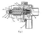
Fig. 1 is a general assembly drawing of the structure of the centrifugal drainage pump according to the present invention. The drawing shows aimpeller 1, ashock absorbing pad 2 of a impeller, ashaft sleeve 3, a rotor shaft 4, ashock absorbing pad 5 of the shaft sleeve, a impeller washer 6, a plastic bearing cover 7, a rubber bearing cover 8, a permanent magnet rotor 9, asealing washer 10, a pump body 11, a bearing 12, abearing seat 13, acoil 14, astator 15 and a pump cover 16. -
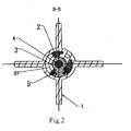
Fig. 2 is the sectional view on the line D-D ofFig. 1 -
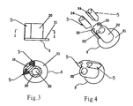
Fig. 3 is the front view and the sectional view of the shaft sleeve. -
Fig. 4 is the view of the shock absorbing pad being connected to the shaft sleeve. -
Fig. 5 is the view of structure of the impeller. - As shown in
Fig. 1 , similarly to the conventional centrifugal drainage pump, the present centrifugal drainage pump comprises a rotor chamber and a pump cover chamber which are mutually separated. The said rotor chamber consists of a pump body 11, a permanent magnet rotor 9, a rotor shaft 4, bearing 12 and a bearing seat. The said pump cover chamber consists of a pump cover 16 with a water-inlet, ashaft sleeve 3, animpeller 1 and an impeller washer 6. In the center of theimpeller 1, there is aholding chamber 17 for holding theshaft sleeve 3 which is in shape of an upside down letter "T". The annular impeller washer 6 locating below the holding chamber of theimpeller 1 closes the holding chamber and keeps theshaft sleeve 3 stay inside of it. Astarting rib 18 is extruded outwardly from surface of the body of the shaft sleeve, whereas a stoppingrib 19 is extruded inwardly from internal surface of the holding chamber of the impeller. After turning forward or backwards for a certain distance, the startingrib 18 interferes with the stoppingrib 19. - The inventive point of the present invention rests in the start-up coupling between the
shaft sleeve 3 and theimpeller 1. Structure of the two components and its coupling will be described in detail. - As the structure sketch of the shaft sleeve shown in
Figs. 3 , the saidshaft sleeve 3 has a tubular body, in the bottom of which there is an annular protruding platform, so that it is in shape of upside down letter "T". Athroughgoing hole 22 for holding the rotor shaft 4 is located in the center of the tubular body and the annular protruding platform. Astarting rib 18 extruding radially and outwardly from the tubular body is moulded integratedly with the shaft sleeve 4. The outside surface of the starting rib is a cambered surface that is flush with the annular protruding platform. The left and right sides in radial direction of the said starting rib are straight flat surfaces. Anotch 23 extending axially is recessed respectively on the both side surfaces. The open end of the notch is narrower than its inner space. Twoshock absorbing pads 5 of the shaft sleeve are fitted onto the left and right side surfaces of the starting rib respectively, the outside of which is also a cambered surface that is flush with of the annular protruding platform, but the internal side of which fits surface of the tubular body. - As it is shown in
Figs. 4 , a strip ofconvex ridge 24 locates on the contacting surface of theshock absorbing pads 5 of the shaft sleeve attaching to the starting rib. The said convex ridge fits in the notch on the both side surfaces of the starting rib mutually. In this way, the convex ridge ofshock absorbing pads 5 of the shaft sleeve can be inserted basipetally into the saidnotch 23 along its axial direction. Because the outside part of the notch is narrower than its inner space, theshock absorbing pads 5 of the shaft sleeve can not be separated from the notch in transverse direction, so that theshock absorbing pads 5 of the shaft sleeve can tightly contact with the side surfaces. -
Figs. 5 are the structure sketch and sectional view of the impeller. Acylindrical holding chamber 17 is arranged in the center of the impeller, and the diameter of thechamber 17 is equal to that of aprotruding platform 21 of the shaft sleeve. A stoppingrib 19 is extruded inwardly from the internal wall of the said holding chamber. The internal side of the said stoppingrib 19 has a cambered surface fitted with the outside surface of theshaft sleeve body 20. The left and right sides of it has flat surfaces. Anotch 25 extending axially is recessed on each of these two surfaces. The open-end of the notch is narrower than inner space of the notch. Twoshock absorbing pads 2 of the impeller are fitting on the said two surfaces. The internal side of the shock absorbing pads of the impeller is a cambered surface fitted with the outside surface of the shaft sleeve body, but its outside is a cambered surface fitted with the internal wall of the shaft sleeve holding chamber. A convex ridge 26 extrudes from the surface of the shock absorbing pad of the impeller which is fitted with the stopping rib. The said convex ridge is coupled with the saidnotch 25 located on either side of the stopping rib so as to form a close contact structure as that of the saidshock absorbing pads 5 of the shaft sleeve with the side surface of the starting rib. - As shown in
Fig. 2 , after putting the shaft sleeve into the holding chamber of the impeller, there is anannular space 27 between the stopping rib of the impeller and the starting rib of the shaft sleeve, so that the starting rib can rotate in this space. Therefore, when the electric motor starts, the shaft sleeve driven by a shaft can interfere with stopping rib of the impeller in order to drive the impeller until it drives the shaft sleeve to turn a certain angle free of load. In this way, the problem of overload that occurs during start-up of a pump has been solved. - In order to improve the swing problem of the impeller, a rotor
shaft holding chamber 28 is build on the top of the impeller, In which the rotor shaft fits. The rotor shaft passing through the shaft sleeve is plugged into the said rotor shaft holding chamber. - The inventive point of the present invention focuses on the attaching structure of the shock absorbing pad. In the present embodiment, there are two pairs of interference contact surfaces between the starting rib and the stopping rib, namely, the left side of the starting rib in the radial direction and the right side of the stopping rib in the radial direction form a pair of interference contact surfaces, whereas the right side of the starting rib in the radial direction and left side of the stopping rib in the radial direction form the other pair of interference contact surfaces. Either shock absorbing pads can absorb impact generated between each pair of interference contact surfaces. Therefore, the above means to place the shock absorbing pad shall fall in the protection scope claimed in the present invention, no matter the shock absorbing pad is placed on the interference contact surfaces of the starting rib or on the interference contact surfaces of the stopping rib, or as it is disclosed in the present invention, on both of the interference contact surfaces of the starting rib and on both of the interference contact surfaces of the stopping rib.
Claims (6)
- A centrifugal drainage pump, comprising a rotor chamber and a pump cover chamber which are separated from one another, wherein the said rotor chamber includes a pump body (11), a permanent magnet rotor (9), a rotor shaft (4), a bearing (12) and a bearing seat; the said pump cover chamber includes a pump cover (16) with a water-inlet, a shaft sleeve (3) and an impeller (1) provided with a holding chamber (17) in its center for holding the shaft sleeve (3), the pump being characterized in that
the shaft sleeve (3) is provided with a tubular body (20), and a starting rib (18) which is integral with the shaft sleeve(3) extrudes outwardly form the tubular body (20) ;
the impeller (1) is provided with a stopping rib (19) projecting inwardly from internal wall of the holding chamber (17), and the starting rib (18) interferes with the stopping rib (19) after it rotates in one direction or reversely for a certain distance,
among pairs of interference contact surfaces between the starting rib and the stopping rib, at least one of each pair of interference contact surfaces has a recessed notch (23 , 25) extending axially and open-end of the notch (23 , 25) is narrower than inner space of the notch; a shock absorbing pad (2, 5) has a convex ridge (24, 26) extruding from its side that contacts with the interference contact surface, and the convex ridge(24, 26) is embedded in the notch ( 23 , 25) in order that the pad tightly contacts with the stopping rib or the starting rib. - A centrifugal drainage pump according to Claim 1, wherein two interference contact surfaces of the starting rib are attached with the shock absorbing pad (5).
- A centrifugal drainage pump according to Claim 1, wherein two interference contact surfaces of the stopping rib are attached with the shock absorbing pad (2).
- A centrifugal drainage pump according to Claim 1, wherein two interference contact surfaces of the starting rib and two interference contact surfaces of the stopping rib are attached with the shock absorbing pad(2, 5).
- A centrifugal drainage pump according to Claim 1, wherein the shaft sleeve (3) is an upside down letter "T" in shape, the upper part of which is the tubular body (20) in cylindrical shape and the lower part of which is an annular protruding platform (21).
- A centrifugal drainage pump according to Claim 1, wherein the impeller has a rotor shaft holding chamber (28) which is arranged on the top of the impeller , and the rotor shaft (4) passes through the shaft sleeve and is plugged into the said rotor shaft holding chamber (28) so that the end of the rotor shaft fitting in the said rotor shaft holding chamber.
Priority Applications (1)
| Application Number | Priority Date | Filing Date | Title |
|---|---|---|---|
| PL06742012T PL1978260T3 (en) | 2006-01-26 | 2006-05-29 | Centrifugal drainage pump |
Applications Claiming Priority (2)
| Application Number | Priority Date | Filing Date | Title |
|---|---|---|---|
| CNU2006200546990U CN2916195Y (en) | 2006-01-26 | 2006-01-26 | A centrifugal drainage pump |
| PCT/CN2006/001124 WO2007085141A1 (en) | 2006-01-26 | 2006-05-29 | Centrifugal drainage pump |
Publications (3)
| Publication Number | Publication Date |
|---|---|
| EP1978260A1 true EP1978260A1 (en) | 2008-10-08 |
| EP1978260A4 EP1978260A4 (en) | 2011-07-06 |
| EP1978260B1 EP1978260B1 (en) | 2017-04-12 |
Family
ID=38187104
Family Applications (1)
| Application Number | Title | Priority Date | Filing Date |
|---|---|---|---|
| EP06742012.5A Expired - Lifetime EP1978260B1 (en) | 2006-01-26 | 2006-05-29 | Centrifugal drainage pump |
Country Status (5)
| Country | Link |
|---|---|
| US (1) | US8057199B2 (en) |
| EP (1) | EP1978260B1 (en) |
| CN (1) | CN2916195Y (en) |
| PL (1) | PL1978260T3 (en) |
| WO (1) | WO2007085141A1 (en) |
Families Citing this family (12)
| Publication number | Priority date | Publication date | Assignee | Title |
|---|---|---|---|---|
| CN101102068B (en) * | 2007-08-08 | 2010-12-29 | 江门市汉宇电器有限公司 | Permanent magnetic synchronization motor for water discharge pump |
| KR101117553B1 (en) * | 2009-08-17 | 2012-03-07 | 주식회사 아모텍 | Waterproof Water Pump Motor and Water Pump Using the Same |
| CN102094832A (en) * | 2011-03-15 | 2011-06-15 | 江门市汉宇电器有限公司 | Vane wheel starting mechanism of alternating-current permanent magnet synchronous motor and drainage pump |
| CN102297143B (en) * | 2011-08-11 | 2013-02-13 | 马建锐 | Permanent magnetic motor drainage pump |
| KR101326503B1 (en) * | 2011-10-26 | 2013-11-08 | 현대자동차주식회사 | Canned motor type of electric water pump |
| DE102012203615B4 (en) * | 2012-03-07 | 2013-11-21 | Hanning Elektro-Werke Gmbh & Co. Kg | pump |
| CN102678895B (en) * | 2012-05-23 | 2015-04-08 | 南京德朔实业有限公司 | Shaft transmission mechanism with noise reduction function |
| DE102012211082A1 (en) * | 2012-06-28 | 2014-01-02 | Robert Bosch Gmbh | Pump for a cooling circuit of a motor vehicle |
| FR3064764B1 (en) * | 2017-03-28 | 2019-06-28 | Hutchinson | DYNAMIC EFFORTS GENERATOR COMPRISING AT LEAST TWO BALOURS AND ACTUATOR COMPRISING SUCH GENERATORS |
| CN107605758A (en) * | 2017-09-04 | 2018-01-19 | 四川宇康供水设备有限公司 | Suitable for the method for supplying water of supply of electric power unstable region |
| CN107605757A (en) * | 2017-09-04 | 2018-01-19 | 四川宇康供水设备有限公司 | Water purification supply system with turn-off reset function |
| CN114576304B (en) * | 2022-03-02 | 2023-09-29 | 安徽智泓净化科技股份有限公司 | Low noise booster pump for reverse osmosis water purifier |
Family Cites Families (45)
| Publication number | Priority date | Publication date | Assignee | Title |
|---|---|---|---|---|
| US2502790A (en) * | 1946-12-02 | 1950-04-04 | Jencick Stephen | Flexible coupling |
| ITPD20010256A1 (en) * | 2001-10-30 | 2003-04-30 | Askoll Holding Srl | PERFECTED DRIVING DEVICE BETWEEN THE ROTOR OF A SYNCHRONOUS MOTOR WITH PERMANENT MAGNETS AND THE OPERATING BODY. |
| JPS5325062Y2 (en) * | 1975-05-20 | 1978-06-27 | ||
| ITPD980058A1 (en) * | 1998-03-19 | 1999-09-19 | Askoll Holding Srl | DRIVING DEVICE, WITH WIDE ROTATION ANGLE BETWEEN THE SYNCHRONOUS PERMANENT MAGNET MOTOR AND THE OPERATING BODY |
| JPS60227016A (en) | 1984-04-23 | 1985-11-12 | Nissan Motor Co Ltd | Deflection joint |
| CA1247388A (en) | 1984-04-27 | 1988-12-28 | Outboard Marine Corporation | Water pump for marine propulsion devices |
| US4703840A (en) | 1984-05-29 | 1987-11-03 | Eaton Corporation | Torsion damping mechanism |
| EP0207430B1 (en) * | 1985-07-01 | 1992-02-26 | EASTHORPE INVESTMENTS Ltd. | Centrifugal pump |
| IT1218569B (en) | 1987-04-22 | 1990-04-19 | Askoll Srl | CENTRIFIGE PUMP PERFECT FOR WASHING MACHINES, DISHWASHER AND APPLIANCES IN GENERAL |
| US4795102A (en) | 1987-12-04 | 1989-01-03 | Maytag Corporation | Dishwasher pump with particle cutter |
| US4992690A (en) | 1988-10-07 | 1991-02-12 | Emerson Electric Co. | Combination motor endshield and pump housing |
| FR2649450A1 (en) | 1989-07-07 | 1991-01-11 | Rena Sa | ROTARY PUMP WITH ELECTRICAL DRIVE |
| US5204567A (en) | 1990-07-09 | 1993-04-20 | Asmo Co., Ltd. | Brushless motor with resilient shaft end-play absorber |
| JP2581655B2 (en) * | 1991-03-08 | 1997-02-12 | トックベアリング株式会社 | High torque damper |
| FR2676510B1 (en) * | 1991-05-14 | 1995-01-06 | Electro Mec Nivernais | QUIET CENTRIFUGAL MOTOR PUMP. |
| CA2085112A1 (en) | 1991-11-08 | 1993-05-09 | Kay Seven Co., Ltd. | Shaft coupling |
| DE69233238T2 (en) | 1991-12-20 | 2004-06-24 | Fisher + Paykel Appliances Ltd., East Tamaki | dishwasher |
| DE4232939A1 (en) * | 1992-10-01 | 1994-04-07 | Massindustrie Gmbh | Starting assistance for hydraulic pump independent of rotation direction - providing free movement between impeller arranged in pump chamber and sync. motor rotor |
| IT1268531B1 (en) | 1993-09-17 | 1997-03-04 | Sole Spa | SELF-LOCKING MOTOR PUMPS |
| JPH07293578A (en) * | 1994-04-25 | 1995-11-07 | Daikin Mfg Co Ltd | Torsion damper for damper disc |
| JP2894596B2 (en) * | 1994-08-19 | 1999-05-24 | トックベアリング株式会社 | Rotary damper and opening / closing device for lid and the like using the damper |
| IT1281839B1 (en) * | 1995-01-19 | 1998-03-03 | Askoll Srl | PERFECTED DEVICE FOR STARTING THE ROTOR OF A SYNCHRONOUS PERMANENT MAGNET MOTOR |
| US5681222A (en) | 1995-02-28 | 1997-10-28 | Weasler Engineering, Inc. | Torque overload clutch coupler for a torque transmitting driveline |
| US5566696A (en) | 1995-05-26 | 1996-10-22 | White Consolidated Industries, Inc. | Dishwasher with balancing vanes on pump impeller |
| DE19717624A1 (en) | 1996-05-17 | 1997-11-20 | Mitsuba Corp | Reduction transmission with impact absorption mechanism |
| NZ314155A (en) | 1997-01-30 | 1999-07-29 | Fisher & Paykel | Dishwasher detergent dispenser located in door recess, having open top and being flushed out by overhead nozzle |
| US5876287A (en) | 1997-07-18 | 1999-03-02 | Lord Corporation | Dual-rate coupling exhibiting an ultra-soft initial spring rate and bonded component therefor |
| ITPD980003A1 (en) * | 1998-01-08 | 1999-07-08 | Askoll Holding Srl | ONE-WAY DRIVING JOINT BETWEEN THE ROTOR OF A PERMANENT MAGNET SYNCHRONOUS MOTOR AND THE OPERATING ORGAN |
| ES2162544B1 (en) * | 1998-12-31 | 2002-07-01 | Fagor S Coop | COUPLING FOR THE TRANSMISSION OF ROTATION IN A SYNCHRONOUS ENGINE. |
| US6478555B1 (en) | 1999-06-16 | 2002-11-12 | Lg Electronics, Inc. | Apparatus for controlling noise and vibration for drain pump |
| CA2363161A1 (en) | 2000-11-21 | 2002-05-21 | Daniel Poissant | Pump unit for viscous liquids |
| US6467587B2 (en) | 2001-02-26 | 2002-10-22 | Woodward Governor Company | Energy absorbing shock mechanism for reducing impact and rotary actuator incorporating same |
| US6709234B2 (en) | 2001-08-31 | 2004-03-23 | Pyrotek, Inc. | Impeller shaft assembly system |
| DE10225948A1 (en) * | 2002-06-11 | 2003-12-24 | Friedr Flender Gmbh A | Elastic coupling |
| DE60306594T2 (en) | 2002-09-03 | 2006-11-16 | Emerson Appliance Motors Europe S.R.L., Moncalieri | Centrifugal pump for household appliances |
| CN2584748Y (en) * | 2002-11-05 | 2003-11-05 | 李柏基 | Anti-theft apparatus for wing |
| ITMI20030263A1 (en) | 2003-02-13 | 2004-08-14 | Manifattura Gomma Finnord S P A | IMPELLER FOR COOLING PUMPS, IN PARTICULAR FOR |
| DE20305335U1 (en) * | 2003-04-02 | 2003-06-05 | BSH Bosch und Siemens Hausgeräte GmbH, 81669 München | Pump and rotor for it |
| DE10320853B4 (en) * | 2003-05-09 | 2005-12-29 | Demag Cranes & Components Gmbh | hoist |
| JP2005162049A (en) * | 2003-12-03 | 2005-06-23 | Toyota Motor Corp | Shock absorber for vehicle |
| EP1553681B1 (en) | 2003-12-31 | 2017-03-15 | Askoll Holding S.r.l. | Coupling device between a rotor of a permanent-magnet synchronous motor and a working part |
| JP4730580B2 (en) * | 2004-04-12 | 2011-07-20 | 日立工機株式会社 | Electric tool and gear device |
| CN2705636Y (en) * | 2004-06-16 | 2005-06-22 | 江门市汉宇电器有限公司 | Centrifugal water discharge pump |
| AU2005202504B1 (en) | 2005-06-09 | 2006-04-27 | Allan Bare | Improved Drive Coupling |
| CN201335023Y (en) * | 2008-12-25 | 2009-10-28 | 常州雷利电机科技有限公司 | Low-noise start equipment of miniature draining pump |
-
2006
- 2006-01-26 CN CNU2006200546990U patent/CN2916195Y/en not_active Expired - Lifetime
- 2006-05-29 EP EP06742012.5A patent/EP1978260B1/en not_active Expired - Lifetime
- 2006-05-29 PL PL06742012T patent/PL1978260T3/en unknown
- 2006-05-29 US US12/064,402 patent/US8057199B2/en active Active
- 2006-05-29 WO PCT/CN2006/001124 patent/WO2007085141A1/en not_active Ceased
Also Published As
| Publication number | Publication date |
|---|---|
| US20080219864A1 (en) | 2008-09-11 |
| EP1978260B1 (en) | 2017-04-12 |
| PL1978260T3 (en) | 2017-11-30 |
| EP1978260A4 (en) | 2011-07-06 |
| CN2916195Y (en) | 2007-06-27 |
| WO2007085141A1 (en) | 2007-08-02 |
| US8057199B2 (en) | 2011-11-15 |
Similar Documents
| Publication | Publication Date | Title |
|---|---|---|
| US7131823B2 (en) | Electrically driven pump and domestic appliance having the pump | |
| US11193493B2 (en) | Water pump | |
| EP1978260B1 (en) | Centrifugal drainage pump | |
| CN109958629A (en) | Pressure fan | |
| CN103503284A (en) | Axial bearing for an electric drive | |
| CN102410230A (en) | Pump device | |
| KR20130138505A (en) | Water pump | |
| CN104365001A (en) | Electric motor drive, particularly a fan drive | |
| KR101527529B1 (en) | Water pump | |
| KR101502285B1 (en) | Electric Water Pump | |
| US7033145B2 (en) | Centrifugal pump for electrical household appliance or the like | |
| JP2012055054A (en) | Fuel pump | |
| US20050260088A1 (en) | Electrically driven pump and domestic appliance having the pump | |
| WO2007133016A8 (en) | Support bearing for submersible motor | |
| CN211209409U (en) | Motors and Electrical Products | |
| KR101371605B1 (en) | Coupling devices for underwater pump | |
| KR200402886Y1 (en) | Drain Pump for Washing Machine | |
| US20060059955A1 (en) | Washing machine | |
| JP6335470B2 (en) | Sliding bearing device and pump device | |
| CN210050094U (en) | Fan bearing system with stable axis | |
| CN209881549U (en) | Motor and shaft current isolation structure thereof | |
| CN213754187U (en) | Bearing support mechanism and motor | |
| CN203500035U (en) | Actuating mechanism for alternating current and permanent magnet drainage pump | |
| KR200342850Y1 (en) | Alien substance removal apparatus in brush-room of alternator for vehicle | |
| CN109402958B (en) | a washing machine |
Legal Events
| Date | Code | Title | Description |
|---|---|---|---|
| PUAI | Public reference made under article 153(3) epc to a published international application that has entered the european phase |
Free format text: ORIGINAL CODE: 0009012 |
|
| 17P | Request for examination filed |
Effective date: 20080304 |
|
| AK | Designated contracting states |
Kind code of ref document: A1 Designated state(s): AT BE BG CH CY CZ DE DK EE ES FI FR GB GR HU IE IS IT LI LT LU LV MC NL PL PT RO SE SI SK TR |
|
| A4 | Supplementary search report drawn up and despatched |
Effective date: 20110609 |
|
| RAP1 | Party data changed (applicant data changed or rights of an application transferred) |
Owner name: JIANGMEN IDEAR HANYU ELECTRICAL JOINT-STOCK CO., L |
|
| RIN1 | Information on inventor provided before grant (corrected) |
Inventor name: LI, MINGXUE Inventor name: SHI, HUASHAN |
|
| RAP1 | Party data changed (applicant data changed or rights of an application transferred) |
Owner name: JIANGMEN IDEAR HANYU ELECTRICAL JOINT-STOCK CO., L |
|
| DAX | Request for extension of the european patent (deleted) | ||
| 17Q | First examination report despatched |
Effective date: 20150410 |
|
| REG | Reference to a national code |
Ref country code: DE Ref legal event code: R079 Ref document number: 602006052234 Country of ref document: DE Free format text: PREVIOUS MAIN CLASS: F04D0013060000 Ipc: F04D0013020000 |
|
| GRAP | Despatch of communication of intention to grant a patent |
Free format text: ORIGINAL CODE: EPIDOSNIGR1 |
|
| STAA | Information on the status of an ep patent application or granted ep patent |
Free format text: STATUS: GRANT OF PATENT IS INTENDED |
|
| RIC1 | Information provided on ipc code assigned before grant |
Ipc: F04D 13/02 20060101AFI20161125BHEP Ipc: F04D 13/06 20060101ALI20161125BHEP Ipc: F16F 15/124 20060101ALI20161125BHEP |
|
| INTG | Intention to grant announced |
Effective date: 20161214 |
|
| RIN1 | Information on inventor provided before grant (corrected) |
Inventor name: SHI, HUASHAN Inventor name: LI, MINGXUE |
|
| GRAS | Grant fee paid |
Free format text: ORIGINAL CODE: EPIDOSNIGR3 |
|
| GRAA | (expected) grant |
Free format text: ORIGINAL CODE: 0009210 |
|
| STAA | Information on the status of an ep patent application or granted ep patent |
Free format text: STATUS: THE PATENT HAS BEEN GRANTED |
|
| AK | Designated contracting states |
Kind code of ref document: B1 Designated state(s): AT BE BG CH CY CZ DE DK EE ES FI FR GB GR HU IE IS IT LI LT LU LV MC NL PL PT RO SE SI SK TR |
|
| REG | Reference to a national code |
Ref country code: GB Ref legal event code: FG4D |
|
| REG | Reference to a national code |
Ref country code: CH Ref legal event code: EP |
|
| REG | Reference to a national code |
Ref country code: IE Ref legal event code: FG4D |
|
| REG | Reference to a national code |
Ref country code: AT Ref legal event code: REF Ref document number: 884197 Country of ref document: AT Kind code of ref document: T Effective date: 20170515 |
|
| REG | Reference to a national code |
Ref country code: DE Ref legal event code: R096 Ref document number: 602006052234 Country of ref document: DE |
|
| REG | Reference to a national code |
Ref country code: NL Ref legal event code: MP Effective date: 20170412 |
|
| REG | Reference to a national code |
Ref country code: LT Ref legal event code: MG4D |
|
| REG | Reference to a national code |
Ref country code: AT Ref legal event code: MK05 Ref document number: 884197 Country of ref document: AT Kind code of ref document: T Effective date: 20170412 |
|
| PG25 | Lapsed in a contracting state [announced via postgrant information from national office to epo] |
Ref country code: NL Free format text: LAPSE BECAUSE OF FAILURE TO SUBMIT A TRANSLATION OF THE DESCRIPTION OR TO PAY THE FEE WITHIN THE PRESCRIBED TIME-LIMIT Effective date: 20170412 |
|
| PG25 | Lapsed in a contracting state [announced via postgrant information from national office to epo] |
Ref country code: FI Free format text: LAPSE BECAUSE OF FAILURE TO SUBMIT A TRANSLATION OF THE DESCRIPTION OR TO PAY THE FEE WITHIN THE PRESCRIBED TIME-LIMIT Effective date: 20170412 Ref country code: ES Free format text: LAPSE BECAUSE OF FAILURE TO SUBMIT A TRANSLATION OF THE DESCRIPTION OR TO PAY THE FEE WITHIN THE PRESCRIBED TIME-LIMIT Effective date: 20170412 Ref country code: AT Free format text: LAPSE BECAUSE OF FAILURE TO SUBMIT A TRANSLATION OF THE DESCRIPTION OR TO PAY THE FEE WITHIN THE PRESCRIBED TIME-LIMIT Effective date: 20170412 Ref country code: LT Free format text: LAPSE BECAUSE OF FAILURE TO SUBMIT A TRANSLATION OF THE DESCRIPTION OR TO PAY THE FEE WITHIN THE PRESCRIBED TIME-LIMIT Effective date: 20170412 Ref country code: GR Free format text: LAPSE BECAUSE OF FAILURE TO SUBMIT A TRANSLATION OF THE DESCRIPTION OR TO PAY THE FEE WITHIN THE PRESCRIBED TIME-LIMIT Effective date: 20170713 |
|
| PG25 | Lapsed in a contracting state [announced via postgrant information from national office to epo] |
Ref country code: LV Free format text: LAPSE BECAUSE OF FAILURE TO SUBMIT A TRANSLATION OF THE DESCRIPTION OR TO PAY THE FEE WITHIN THE PRESCRIBED TIME-LIMIT Effective date: 20170412 Ref country code: IS Free format text: LAPSE BECAUSE OF FAILURE TO SUBMIT A TRANSLATION OF THE DESCRIPTION OR TO PAY THE FEE WITHIN THE PRESCRIBED TIME-LIMIT Effective date: 20170812 Ref country code: SE Free format text: LAPSE BECAUSE OF FAILURE TO SUBMIT A TRANSLATION OF THE DESCRIPTION OR TO PAY THE FEE WITHIN THE PRESCRIBED TIME-LIMIT Effective date: 20170412 Ref country code: BG Free format text: LAPSE BECAUSE OF FAILURE TO SUBMIT A TRANSLATION OF THE DESCRIPTION OR TO PAY THE FEE WITHIN THE PRESCRIBED TIME-LIMIT Effective date: 20170712 |
|
| REG | Reference to a national code |
Ref country code: DE Ref legal event code: R119 Ref document number: 602006052234 Country of ref document: DE |
|
| REG | Reference to a national code |
Ref country code: CH Ref legal event code: PL |
|
| PG25 | Lapsed in a contracting state [announced via postgrant information from national office to epo] |
Ref country code: DK Free format text: LAPSE BECAUSE OF FAILURE TO SUBMIT A TRANSLATION OF THE DESCRIPTION OR TO PAY THE FEE WITHIN THE PRESCRIBED TIME-LIMIT Effective date: 20170412 Ref country code: EE Free format text: LAPSE BECAUSE OF FAILURE TO SUBMIT A TRANSLATION OF THE DESCRIPTION OR TO PAY THE FEE WITHIN THE PRESCRIBED TIME-LIMIT Effective date: 20170412 Ref country code: SK Free format text: LAPSE BECAUSE OF FAILURE TO SUBMIT A TRANSLATION OF THE DESCRIPTION OR TO PAY THE FEE WITHIN THE PRESCRIBED TIME-LIMIT Effective date: 20170412 Ref country code: MC Free format text: LAPSE BECAUSE OF FAILURE TO SUBMIT A TRANSLATION OF THE DESCRIPTION OR TO PAY THE FEE WITHIN THE PRESCRIBED TIME-LIMIT Effective date: 20170412 Ref country code: RO Free format text: LAPSE BECAUSE OF FAILURE TO SUBMIT A TRANSLATION OF THE DESCRIPTION OR TO PAY THE FEE WITHIN THE PRESCRIBED TIME-LIMIT Effective date: 20170412 Ref country code: CZ Free format text: LAPSE BECAUSE OF FAILURE TO SUBMIT A TRANSLATION OF THE DESCRIPTION OR TO PAY THE FEE WITHIN THE PRESCRIBED TIME-LIMIT Effective date: 20170412 |
|
| PLBE | No opposition filed within time limit |
Free format text: ORIGINAL CODE: 0009261 |
|
| STAA | Information on the status of an ep patent application or granted ep patent |
Free format text: STATUS: NO OPPOSITION FILED WITHIN TIME LIMIT |
|
| REG | Reference to a national code |
Ref country code: IE Ref legal event code: MM4A |
|
| PG25 | Lapsed in a contracting state [announced via postgrant information from national office to epo] |
Ref country code: LI Free format text: LAPSE BECAUSE OF NON-PAYMENT OF DUE FEES Effective date: 20170531 Ref country code: CH Free format text: LAPSE BECAUSE OF NON-PAYMENT OF DUE FEES Effective date: 20170531 |
|
| REG | Reference to a national code |
Ref country code: FR Ref legal event code: ST Effective date: 20180131 |
|
| 26N | No opposition filed |
Effective date: 20180115 |
|
| GBPC | Gb: european patent ceased through non-payment of renewal fee |
Effective date: 20170712 |
|
| PG25 | Lapsed in a contracting state [announced via postgrant information from national office to epo] |
Ref country code: LU Free format text: LAPSE BECAUSE OF NON-PAYMENT OF DUE FEES Effective date: 20170529 |
|
| REG | Reference to a national code |
Ref country code: BE Ref legal event code: MM Effective date: 20170531 |
|
| PG25 | Lapsed in a contracting state [announced via postgrant information from national office to epo] |
Ref country code: GB Free format text: LAPSE BECAUSE OF NON-PAYMENT OF DUE FEES Effective date: 20170712 Ref country code: IE Free format text: LAPSE BECAUSE OF NON-PAYMENT OF DUE FEES Effective date: 20170529 Ref country code: DE Free format text: LAPSE BECAUSE OF NON-PAYMENT OF DUE FEES Effective date: 20171201 |
|
| PG25 | Lapsed in a contracting state [announced via postgrant information from national office to epo] |
Ref country code: FR Free format text: LAPSE BECAUSE OF NON-PAYMENT OF DUE FEES Effective date: 20170612 Ref country code: SI Free format text: LAPSE BECAUSE OF FAILURE TO SUBMIT A TRANSLATION OF THE DESCRIPTION OR TO PAY THE FEE WITHIN THE PRESCRIBED TIME-LIMIT Effective date: 20170412 |
|
| PG25 | Lapsed in a contracting state [announced via postgrant information from national office to epo] |
Ref country code: BE Free format text: LAPSE BECAUSE OF NON-PAYMENT OF DUE FEES Effective date: 20170531 |
|
| PG25 | Lapsed in a contracting state [announced via postgrant information from national office to epo] |
Ref country code: HU Free format text: LAPSE BECAUSE OF FAILURE TO SUBMIT A TRANSLATION OF THE DESCRIPTION OR TO PAY THE FEE WITHIN THE PRESCRIBED TIME-LIMIT; INVALID AB INITIO Effective date: 20060529 |
|
| PG25 | Lapsed in a contracting state [announced via postgrant information from national office to epo] |
Ref country code: CY Free format text: LAPSE BECAUSE OF NON-PAYMENT OF DUE FEES Effective date: 20170412 |
|
| PG25 | Lapsed in a contracting state [announced via postgrant information from national office to epo] |
Ref country code: PT Free format text: LAPSE BECAUSE OF FAILURE TO SUBMIT A TRANSLATION OF THE DESCRIPTION OR TO PAY THE FEE WITHIN THE PRESCRIBED TIME-LIMIT Effective date: 20170412 |
|
| PGFP | Annual fee paid to national office [announced via postgrant information from national office to epo] |
Ref country code: PL Payment date: 20250516 Year of fee payment: 20 |
|
| PGFP | Annual fee paid to national office [announced via postgrant information from national office to epo] |
Ref country code: IT Payment date: 20250530 Year of fee payment: 20 |
|
| PGFP | Annual fee paid to national office [announced via postgrant information from national office to epo] |
Ref country code: TR Payment date: 20250522 Year of fee payment: 20 |