EP1978243A2 - Leistungsschaltkasten für Motorteile eines Kraftfahrzeugs - Google Patents
Leistungsschaltkasten für Motorteile eines Kraftfahrzeugs Download PDFInfo
- Publication number
- EP1978243A2 EP1978243A2 EP08153892A EP08153892A EP1978243A2 EP 1978243 A2 EP1978243 A2 EP 1978243A2 EP 08153892 A EP08153892 A EP 08153892A EP 08153892 A EP08153892 A EP 08153892A EP 1978243 A2 EP1978243 A2 EP 1978243A2
- Authority
- EP
- European Patent Office
- Prior art keywords
- engine
- fuel
- control
- box according
- activation
- Prior art date
- Legal status (The legal status is an assumption and is not a legal conclusion. Google has not performed a legal analysis and makes no representation as to the accuracy of the status listed.)
- Withdrawn
Links
Images

Classifications
-
- F—MECHANICAL ENGINEERING; LIGHTING; HEATING; WEAPONS; BLASTING
- F02—COMBUSTION ENGINES; HOT-GAS OR COMBUSTION-PRODUCT ENGINE PLANTS
- F02D—CONTROLLING COMBUSTION ENGINES
- F02D41/00—Electrical control of supply of combustible mixture or its constituents
- F02D41/24—Electrical control of supply of combustible mixture or its constituents characterised by the use of digital means
- F02D41/26—Electrical control of supply of combustible mixture or its constituents characterised by the use of digital means using computer, e.g. microprocessor
- F02D41/266—Electrical control of supply of combustible mixture or its constituents characterised by the use of digital means using computer, e.g. microprocessor the computer being backed-up or assisted by another circuit, e.g. analogue
-
- F—MECHANICAL ENGINEERING; LIGHTING; HEATING; WEAPONS; BLASTING
- F01—MACHINES OR ENGINES IN GENERAL; ENGINE PLANTS IN GENERAL; STEAM ENGINES
- F01N—GAS-FLOW SILENCERS OR EXHAUST APPARATUS FOR MACHINES OR ENGINES IN GENERAL; GAS-FLOW SILENCERS OR EXHAUST APPARATUS FOR INTERNAL-COMBUSTION ENGINES
- F01N13/00—Exhaust or silencing apparatus characterised by constructional features
- F01N13/009—Exhaust or silencing apparatus characterised by constructional features having two or more separate purifying devices arranged in series
- F01N13/0097—Exhaust or silencing apparatus characterised by constructional features having two or more separate purifying devices arranged in series the purifying devices are arranged in a single housing
-
- F—MECHANICAL ENGINEERING; LIGHTING; HEATING; WEAPONS; BLASTING
- F01—MACHINES OR ENGINES IN GENERAL; ENGINE PLANTS IN GENERAL; STEAM ENGINES
- F01N—GAS-FLOW SILENCERS OR EXHAUST APPARATUS FOR MACHINES OR ENGINES IN GENERAL; GAS-FLOW SILENCERS OR EXHAUST APPARATUS FOR INTERNAL-COMBUSTION ENGINES
- F01N3/00—Exhaust or silencing apparatus having means for purifying, rendering innocuous, or otherwise treating exhaust
- F01N3/02—Exhaust or silencing apparatus having means for purifying, rendering innocuous, or otherwise treating exhaust for cooling, or for removing solid constituents of, exhaust
- F01N3/021—Exhaust or silencing apparatus having means for purifying, rendering innocuous, or otherwise treating exhaust for cooling, or for removing solid constituents of, exhaust by means of filters
- F01N3/023—Exhaust or silencing apparatus having means for purifying, rendering innocuous, or otherwise treating exhaust for cooling, or for removing solid constituents of, exhaust by means of filters using means for regenerating the filters, e.g. by burning trapped particles
- F01N3/025—Exhaust or silencing apparatus having means for purifying, rendering innocuous, or otherwise treating exhaust for cooling, or for removing solid constituents of, exhaust by means of filters using means for regenerating the filters, e.g. by burning trapped particles using fuel burner or by adding fuel to exhaust
- F01N3/0253—Exhaust or silencing apparatus having means for purifying, rendering innocuous, or otherwise treating exhaust for cooling, or for removing solid constituents of, exhaust by means of filters using means for regenerating the filters, e.g. by burning trapped particles using fuel burner or by adding fuel to exhaust adding fuel to exhaust gases
-
- F—MECHANICAL ENGINEERING; LIGHTING; HEATING; WEAPONS; BLASTING
- F01—MACHINES OR ENGINES IN GENERAL; ENGINE PLANTS IN GENERAL; STEAM ENGINES
- F01N—GAS-FLOW SILENCERS OR EXHAUST APPARATUS FOR MACHINES OR ENGINES IN GENERAL; GAS-FLOW SILENCERS OR EXHAUST APPARATUS FOR INTERNAL-COMBUSTION ENGINES
- F01N3/00—Exhaust or silencing apparatus having means for purifying, rendering innocuous, or otherwise treating exhaust
- F01N3/02—Exhaust or silencing apparatus having means for purifying, rendering innocuous, or otherwise treating exhaust for cooling, or for removing solid constituents of, exhaust
- F01N3/021—Exhaust or silencing apparatus having means for purifying, rendering innocuous, or otherwise treating exhaust for cooling, or for removing solid constituents of, exhaust by means of filters
- F01N3/033—Exhaust or silencing apparatus having means for purifying, rendering innocuous, or otherwise treating exhaust for cooling, or for removing solid constituents of, exhaust by means of filters in combination with other devices
- F01N3/035—Exhaust or silencing apparatus having means for purifying, rendering innocuous, or otherwise treating exhaust for cooling, or for removing solid constituents of, exhaust by means of filters in combination with other devices with catalytic reactors
-
- F—MECHANICAL ENGINEERING; LIGHTING; HEATING; WEAPONS; BLASTING
- F01—MACHINES OR ENGINES IN GENERAL; ENGINE PLANTS IN GENERAL; STEAM ENGINES
- F01N—GAS-FLOW SILENCERS OR EXHAUST APPARATUS FOR MACHINES OR ENGINES IN GENERAL; GAS-FLOW SILENCERS OR EXHAUST APPARATUS FOR INTERNAL-COMBUSTION ENGINES
- F01N9/00—Electrical control of exhaust gas treating apparatus
- F01N9/002—Electrical control of exhaust gas treating apparatus of filter regeneration
-
- F—MECHANICAL ENGINEERING; LIGHTING; HEATING; WEAPONS; BLASTING
- F02—COMBUSTION ENGINES; HOT-GAS OR COMBUSTION-PRODUCT ENGINE PLANTS
- F02P—IGNITION, OTHER THAN COMPRESSION IGNITION, FOR INTERNAL-COMBUSTION ENGINES; TESTING OF IGNITION TIMING IN COMPRESSION-IGNITION ENGINES
- F02P19/00—Incandescent ignition, e.g. during starting of internal combustion engines; Combination of incandescent and spark ignition
- F02P19/02—Incandescent ignition, e.g. during starting of internal combustion engines; Combination of incandescent and spark ignition electric, e.g. layout of circuits of apparatus having glowing plugs
-
- F—MECHANICAL ENGINEERING; LIGHTING; HEATING; WEAPONS; BLASTING
- F01—MACHINES OR ENGINES IN GENERAL; ENGINE PLANTS IN GENERAL; STEAM ENGINES
- F01N—GAS-FLOW SILENCERS OR EXHAUST APPARATUS FOR MACHINES OR ENGINES IN GENERAL; GAS-FLOW SILENCERS OR EXHAUST APPARATUS FOR INTERNAL-COMBUSTION ENGINES
- F01N2610/00—Adding substances to exhaust gases
- F01N2610/10—Adding substances to exhaust gases the substance being heated, e.g. by heating tank or supply line of the added substance
-
- F—MECHANICAL ENGINEERING; LIGHTING; HEATING; WEAPONS; BLASTING
- F01—MACHINES OR ENGINES IN GENERAL; ENGINE PLANTS IN GENERAL; STEAM ENGINES
- F01N—GAS-FLOW SILENCERS OR EXHAUST APPARATUS FOR MACHINES OR ENGINES IN GENERAL; GAS-FLOW SILENCERS OR EXHAUST APPARATUS FOR INTERNAL-COMBUSTION ENGINES
- F01N2610/00—Adding substances to exhaust gases
- F01N2610/10—Adding substances to exhaust gases the substance being heated, e.g. by heating tank or supply line of the added substance
- F01N2610/107—Adding substances to exhaust gases the substance being heated, e.g. by heating tank or supply line of the added substance using glow plug heating elements
-
- F—MECHANICAL ENGINEERING; LIGHTING; HEATING; WEAPONS; BLASTING
- F02—COMBUSTION ENGINES; HOT-GAS OR COMBUSTION-PRODUCT ENGINE PLANTS
- F02D—CONTROLLING COMBUSTION ENGINES
- F02D41/00—Electrical control of supply of combustible mixture or its constituents
- F02D41/02—Circuit arrangements for generating control signals
- F02D41/021—Introducing corrections for particular conditions exterior to the engine
- F02D41/0235—Introducing corrections for particular conditions exterior to the engine in relation with the state of the exhaust gas treating apparatus
- F02D41/027—Introducing corrections for particular conditions exterior to the engine in relation with the state of the exhaust gas treating apparatus to purge or regenerate the exhaust gas treating apparatus
- F02D41/029—Introducing corrections for particular conditions exterior to the engine in relation with the state of the exhaust gas treating apparatus to purge or regenerate the exhaust gas treating apparatus the exhaust gas treating apparatus being a particulate filter
-
- F—MECHANICAL ENGINEERING; LIGHTING; HEATING; WEAPONS; BLASTING
- F02—COMBUSTION ENGINES; HOT-GAS OR COMBUSTION-PRODUCT ENGINE PLANTS
- F02P—IGNITION, OTHER THAN COMPRESSION IGNITION, FOR INTERNAL-COMBUSTION ENGINES; TESTING OF IGNITION TIMING IN COMPRESSION-IGNITION ENGINES
- F02P19/00—Incandescent ignition, e.g. during starting of internal combustion engines; Combination of incandescent and spark ignition
- F02P19/02—Incandescent ignition, e.g. during starting of internal combustion engines; Combination of incandescent and spark ignition electric, e.g. layout of circuits of apparatus having glowing plugs
- F02P19/021—Incandescent ignition, e.g. during starting of internal combustion engines; Combination of incandescent and spark ignition electric, e.g. layout of circuits of apparatus having glowing plugs characterised by power delivery controls
- F02P19/023—Individual control of the glow plugs
-
- F—MECHANICAL ENGINEERING; LIGHTING; HEATING; WEAPONS; BLASTING
- F02—COMBUSTION ENGINES; HOT-GAS OR COMBUSTION-PRODUCT ENGINE PLANTS
- F02P—IGNITION, OTHER THAN COMPRESSION IGNITION, FOR INTERNAL-COMBUSTION ENGINES; TESTING OF IGNITION TIMING IN COMPRESSION-IGNITION ENGINES
- F02P19/00—Incandescent ignition, e.g. during starting of internal combustion engines; Combination of incandescent and spark ignition
- F02P19/02—Incandescent ignition, e.g. during starting of internal combustion engines; Combination of incandescent and spark ignition electric, e.g. layout of circuits of apparatus having glowing plugs
- F02P19/026—Glow plug actuation during engine operation
-
- Y—GENERAL TAGGING OF NEW TECHNOLOGICAL DEVELOPMENTS; GENERAL TAGGING OF CROSS-SECTIONAL TECHNOLOGIES SPANNING OVER SEVERAL SECTIONS OF THE IPC; TECHNICAL SUBJECTS COVERED BY FORMER USPC CROSS-REFERENCE ART COLLECTIONS [XRACs] AND DIGESTS
- Y02—TECHNOLOGIES OR APPLICATIONS FOR MITIGATION OR ADAPTATION AGAINST CLIMATE CHANGE
- Y02T—CLIMATE CHANGE MITIGATION TECHNOLOGIES RELATED TO TRANSPORTATION
- Y02T10/00—Road transport of goods or passengers
- Y02T10/10—Internal combustion engine [ICE] based vehicles
- Y02T10/40—Engine management systems
Definitions
- the invention relates to the control devices of the electrical components of a motor vehicle engine and its pollution control system.
- the pollutants resulting from the combustion of a motor vehicle engine are mainly unburnt hydrocarbons, nitrogen oxides (nitrogen monoxide NO and nitrogen dioxide NO 2 ) , oxides of carbon (carbon monoxide CO) and in the case of diesel engines and gasoline direct injection engines, carbonaceous solid particles.
- the clean-up of motor vehicles involves various after-treatment systems to remove the pollutants produced by the engine, such as catalysts and the particulate filter in the case of diesel engines.
- the particulate filter can filter out solid particles present in the exhaust gas of diesel engines. Once trapped within the filter, the particles must be removed periodically by raising the temperature to 450-700 ° C within the filter to cause their combustion. This operation is commonly called “regeneration" of the particulate filter. Conventionally the energy required for regeneration is provided by an increase in the temperature of the exhaust gas.
- the excess energy in the exhaust compared to the normal operation of the engine is provided by the use of post-injections, that is to say of late fuel injections, after the top dead center of the cycle, or by a degradation of the efficiency of combustion.
- a post-injection it may burn completely or partially in the engine, generating an increase in the temperature of the exhaust gas or, if it is sufficiently late, lead to an increase in the amounts of CO and HC exhaust that oxidize upon arriving at the oxidation catalyst to generate heat.
- This method causes a strong thermal stress on the catalyst closest to the engine which is subjected to each regeneration at a high temperature rise.
- the turbocharger and the exhaust manifold are also subjected to high temperatures.
- the heating methods from the engine lead to the dilution of diesel oil in the lubricating oil thereof, which is detrimental to its life.
- the gas oil is introduced in vapor form, directly into the exhaust line, upstream of the catalyst and the particulate filter.
- the oxidation of the hydrocarbons thus sent on the catalyst causes a significant release of heat therein and consequently increases the temperature of the gases at the inlet of the particulate filter.
- the figure 1 proposes a scheme of operation of this system. It consists of a pump 1 connected to a heating plug 2 followed by a vaporization device 3 whose outlet opens into the exhaust duct, upstream of the catalyst associated with the particulate filter.
- the pump 1 sends the fuel, which it took in the vehicle tank, in the vaporization system 3. Passing near the spark plug 2, the fuel is raised enough temperature to make it pass the vapor phase. It is in this form that it is introduced, by the vaporization system, into the exhaust duct.
- the candle used must be high power, its power consumption can exceed 20A. Its piloting therefore requires a power interface associated with the engine computer.
- the object of the invention is therefore to propose a new arrangement of power interface systems of the engine computer to integrate the control of the spark plug of the fuel vaporization device.
- the subject of the present invention is a power control unit for motor vehicle engine components, said engine comprising plugs for preheating the injected fuel, a control computer for its components and a gas exhaust line.
- a catalyst associated with a particulate filter and a fuel injection system composed of a pump connected to a fuel-burning plug followed by a vaporization device whose outlet opens into the fuel line; exhaust, upstream of the catalyst.
- this power control unit is connected to the engine control unit and it comprises means for controlling the activation of the engine glow plugs and the heating plug of the fuel vaporization system.
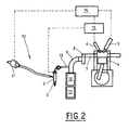
- a motor 4 for example a diesel engine, provided with injectors 5 and glow plugs 6.
- an exhaust manifold 7 and a turbocharger 8 opening into the exhaust duct 9 in which are placed a catalyst 10 associated with a particulate filter 11.
- a system 12 allows the introduction of fuel such as diesel fuel, in the exhaust line.
- This system consists, as mentioned above, of a pump 1 connected to a glow plug 2 followed by a spraying device 3 whose outlet 13 opens into the exhaust duct 9, upstream of catalyst 10 associated with the particulate filter 11.
- the pump 1 is fed by the circuit connected to the fuel tank of the vehicle and sends the fuel that it takes in this tank in the vaporization system 3. Passing near the spark plug 2, the fuel suffers a sufficient temperature rise to make it pass in the vapor phase. It is in this form that it is introduced, by the vaporization system, into the duct 9.
- a computer 14 controls the various components of the engine and, in particular, the injectors 5 and the pump 1 of the fuel introduction system 12 to the exhaust.
- the engine computer 14 is also connected to a housing 15 incorporating control and diagnostic circuits. These circuits are able to provide the necessary power to control, both, the glow plugs 6 of the engine and the spark plug 2 of heating system 12 for introducing fuel to the exhaust.
- the diagnostic circuits also integrated in the housing 15 determine the operating state of the spark plugs and deliver a signal towards the computer 14 in case of malfunction of one or more of them.
- the figure 3 presents an operating diagram of the device according to the invention in the case of a four-cylinder engine.
- the engine computer sends to the housing 15 the control signals of the glow plugs 6 and the spark plug 2 of the fuel vaporization system 12.
- the housing 15 sends the computer 14, signals corresponding to the operating state of these candles.
- the housing 15 will accordingly control the spark plugs according to different strategies, depending on the engine operating phases and certain events that may affect this operation or that of the associated devices.
- the housing 15 can activate the glow plugs 6 one after the other instead of the usual simultaneous activation .
- the housing 15 will activate, normally, the spark plug 2 of the fuel vaporization system 12 but will at the same time control the operation of the glow plugs 6.
- control and diagnostic unit that has just been described thus makes it possible to control the glow plugs of the engine as well as the spark plug of the fuel vaporization system without having to integrate a power interface into the engine ECU. This reduces the need for heat dissipation of the latter.
- the signals exchanged between the engine computer and the housing are low current signals that do not cause significant thermal rise in the computer.
Landscapes
- Engineering & Computer Science (AREA)
- Chemical & Material Sciences (AREA)
- General Engineering & Computer Science (AREA)
- Combustion & Propulsion (AREA)
- Mechanical Engineering (AREA)
- Computer Hardware Design (AREA)
- Microelectronics & Electronic Packaging (AREA)
- Chemical Kinetics & Catalysis (AREA)
- Exhaust Gas After Treatment (AREA)
- Processes For Solid Components From Exhaust (AREA)
- Control Of Vehicle Engines Or Engines For Specific Uses (AREA)
Applications Claiming Priority (1)
| Application Number | Priority Date | Filing Date | Title |
|---|---|---|---|
| FR0754377A FR2914702B1 (fr) | 2007-04-06 | 2007-04-06 | Boitier de commande de puissance pour composants de moteur de vehicule automobile |
Publications (2)
| Publication Number | Publication Date |
|---|---|
| EP1978243A2 true EP1978243A2 (de) | 2008-10-08 |
| EP1978243A3 EP1978243A3 (de) | 2010-01-20 |
Family
ID=38668805
Family Applications (1)
| Application Number | Title | Priority Date | Filing Date |
|---|---|---|---|
| EP08153892A Withdrawn EP1978243A3 (de) | 2007-04-06 | 2008-04-01 | Leistungsschaltkasten für Motorteile eines Kraftfahrzeugs |
Country Status (2)
| Country | Link |
|---|---|
| EP (1) | EP1978243A3 (de) |
| FR (1) | FR2914702B1 (de) |
Cited By (1)
| Publication number | Priority date | Publication date | Assignee | Title |
|---|---|---|---|---|
| FR2960031A1 (fr) * | 2010-05-12 | 2011-11-18 | Peugeot Citroen Automobiles Sa | Procede de commande des bougies de prechauffage d'un moteur |
Citations (1)
| Publication number | Priority date | Publication date | Assignee | Title |
|---|---|---|---|---|
| EP1369557A1 (de) | 2002-06-07 | 2003-12-10 | Zeuna-Stärker Gmbh & Co Kg | Kraftfahrzeug mit einem Diesel-Antriebsmotor mit mittels Kraftstoffdampfeindüsung diskontinuierlich regenerierbarem Abgasreinigungssystem |
Family Cites Families (5)
| Publication number | Priority date | Publication date | Assignee | Title |
|---|---|---|---|---|
| DE3624664C2 (de) * | 1986-07-22 | 1995-08-03 | Bosch Gmbh Robert | Schnittstelle zwischen einer zentralen Motorsteuerung und einer Glühanlage eines Dieselmotors |
| DE3713835A1 (de) * | 1987-04-24 | 1988-11-03 | Beru Werk Ruprecht Gmbh Co A | Verfahren und vorrichtung zum schnellaufheizen einer elektrischen heizvorrichtung |
| DE19855385A1 (de) * | 1998-12-01 | 2000-06-08 | Bosch Gmbh Robert | Vorrichtung zum Nachbehandeln von Abgasen einer Brennkraftmaschine |
| JP2004225579A (ja) * | 2003-01-21 | 2004-08-12 | Isuzu Motors Ltd | 排気ガス浄化システム |
| US7469177B2 (en) * | 2005-06-17 | 2008-12-23 | Honeywell International Inc. | Distributed control architecture for powertrains |
-
2007
- 2007-04-06 FR FR0754377A patent/FR2914702B1/fr not_active Expired - Fee Related
-
2008
- 2008-04-01 EP EP08153892A patent/EP1978243A3/de not_active Withdrawn
Patent Citations (1)
| Publication number | Priority date | Publication date | Assignee | Title |
|---|---|---|---|---|
| EP1369557A1 (de) | 2002-06-07 | 2003-12-10 | Zeuna-Stärker Gmbh & Co Kg | Kraftfahrzeug mit einem Diesel-Antriebsmotor mit mittels Kraftstoffdampfeindüsung diskontinuierlich regenerierbarem Abgasreinigungssystem |
Cited By (1)
| Publication number | Priority date | Publication date | Assignee | Title |
|---|---|---|---|---|
| FR2960031A1 (fr) * | 2010-05-12 | 2011-11-18 | Peugeot Citroen Automobiles Sa | Procede de commande des bougies de prechauffage d'un moteur |
Also Published As
| Publication number | Publication date |
|---|---|
| FR2914702B1 (fr) | 2009-06-12 |
| FR2914702A1 (fr) | 2008-10-10 |
| EP1978243A3 (de) | 2010-01-20 |
Similar Documents
| Publication | Publication Date | Title |
|---|---|---|
| EP1310656B1 (de) | Vorrichtung zur Regenerierung eines in eine Abgasanlage einer Brennkraftmaschine eines Kraftfahrzeugs integrierten Abgasbehandlungssystems | |
| EP1086304B1 (de) | Regenerierungssystem für einen dieselmotorabgaspartikelfilter | |
| JP2011033021A (ja) | ディーゼルパーティキュレートフィルタ再生用の排気ガス加熱 | |
| FR2774427A1 (fr) | Systeme d'aide a la regeneration d'un filtre a particules integre dans une ligne d'echappement de moteur diesel notamment pour vehicule automobile | |
| US8499556B2 (en) | Exhaust purification system with a diesel particulate filter and a method of cleaning said filter | |
| EP1103702B1 (de) | Regelungverfahren eines Partikelfilters und Regelungsverfahren einer Brennkraftmaschine | |
| FR2833301A1 (fr) | Procede de gestion de l'energie dans un vehicule automobile equipe d'un moteur a combustion interne et d'un filtre a particules | |
| EP1130227A1 (de) | Vorrichtung zur Regenerierung eines Partikelfilters in einer selbstgezündeten Brennkraftmaschine | |
| EP1132583B1 (de) | Vorrichtung zur Regeneration einens Partikelfilters in einem Dieselmotor | |
| FR2914702A1 (fr) | Boitier de commande de puissance pour composants de moteur de vehicule automobile | |
| WO2006005867A1 (fr) | Systeme d'aide a la regeneration de moyens de depollution associes a des moyens formant catalyseur | |
| WO2024079298A1 (fr) | Procédé de chauffage d'un catalyseur dans un véhicule à motirisation hybride | |
| EP1160435B1 (de) | System für die Unterstützung der Regeneration eines Partikelfilters enthalten in der Auspuffslinie eines Dieselfahrzeugmotors | |
| FR2880065A1 (fr) | Dispositif de depollution des gaz d'echappement | |
| FR2926518A1 (fr) | Procede de commande d'un moteur hybride et moteur correspondant | |
| FR2909044A1 (fr) | Dispositif de securite anti-incendie pour vehicule automobile | |
| FR2774428A1 (fr) | Systeme d'aide a la regeneration d'un filtre a particules integre dans une ligne d'echappement de moteur diesel notamment de vehicule automobile | |
| EP1672205A1 (de) | Verfahren und Vorrichtung zur Vorbereitung eines Motors eines Kraftfahrzeugs für die Regeneration eines Partikelfilters | |
| EP4031754B1 (de) | Verfahren zur regeneration eines partikelfilters eines hybridfahrzeugs | |
| FR2774422A1 (fr) | Systeme d'aide a la regeneration d'un filtre a particules integre dans une ligne d'echappement d'un moteur diesel notamment de vehicule automobile | |
| EP1411228A1 (de) | Verfahren zur Regeneration eines Partikelfilters und Vorrichtung zur Durchführung | |
| EP1832728A1 (de) | Verfahren zur Reinigung von Abgasen eines Verbrennungsmotors | |
| FR2928686A3 (fr) | Procede de regeneration d'un dispositif de post-traitement d'un systeme d'echappement d'un moteur a combustion interne | |
| FR2879242A1 (fr) | Procede de controle de la regeneration d'un filtre a particules electrostatique | |
| FR2804176A1 (fr) | Systeme d'aide a la regeneration d'un filtre a particules integre dans une ligne d'echappement d'un moteur diesel de vehicule automobile |
Legal Events
| Date | Code | Title | Description |
|---|---|---|---|
| PUAI | Public reference made under article 153(3) epc to a published international application that has entered the european phase |
Free format text: ORIGINAL CODE: 0009012 |
|
| AK | Designated contracting states |
Kind code of ref document: A2 Designated state(s): AT BE BG CH CY CZ DE DK EE ES FI FR GB GR HR HU IE IS IT LI LT LU LV MC MT NL NO PL PT RO SE SI SK TR |
|
| AX | Request for extension of the european patent |
Extension state: AL BA MK RS |
|
| PUAL | Search report despatched |
Free format text: ORIGINAL CODE: 0009013 |
|
| AK | Designated contracting states |
Kind code of ref document: A3 Designated state(s): AT BE BG CH CY CZ DE DK EE ES FI FR GB GR HR HU IE IS IT LI LT LU LV MC MT NL NO PL PT RO SE SI SK TR |
|
| AX | Request for extension of the european patent |
Extension state: AL BA MK RS |
|
| 17P | Request for examination filed |
Effective date: 20100119 |
|
| 17Q | First examination report despatched |
Effective date: 20100219 |
|
| AKX | Designation fees paid |
Designated state(s): AT BE BG CH CY CZ DE DK EE ES FI FR GB GR HR HU IE IS IT LI LT LU LV MC MT NL NO PL PT RO SE SI SK TR |
|
| STAA | Information on the status of an ep patent application or granted ep patent |
Free format text: STATUS: THE APPLICATION IS DEEMED TO BE WITHDRAWN |
|
| 18D | Application deemed to be withdrawn |
Effective date: 20141101 |