EP1978227A1 - Misfire determination device, hybrid automobile, and misfire determination method - Google Patents
Misfire determination device, hybrid automobile, and misfire determination method Download PDFInfo
- Publication number
- EP1978227A1 EP1978227A1 EP06833298A EP06833298A EP1978227A1 EP 1978227 A1 EP1978227 A1 EP 1978227A1 EP 06833298 A EP06833298 A EP 06833298A EP 06833298 A EP06833298 A EP 06833298A EP 1978227 A1 EP1978227 A1 EP 1978227A1
- Authority
- EP
- European Patent Office
- Prior art keywords
- misfire
- engine
- threshold value
- detection
- gear position
- Prior art date
- Legal status (The legal status is an assumption and is not a legal conclusion. Google has not performed a legal analysis and makes no representation as to the accuracy of the status listed.)
- Granted
Links
- 238000000034 method Methods 0.000 title abstract description 47
- 238000001514 detection method Methods 0.000 claims abstract description 146
- 230000005540 biological transmission Effects 0.000 claims abstract description 109
- 230000007246 mechanism Effects 0.000 claims abstract description 53
- 238000002485 combustion reaction Methods 0.000 claims description 50
- 230000008859 change Effects 0.000 claims description 16
- 230000007423 decrease Effects 0.000 claims description 6
- 230000008569 process Effects 0.000 abstract description 21
- 230000000694 effects Effects 0.000 abstract description 10
- 230000010354 integration Effects 0.000 description 13
- 230000004044 response Effects 0.000 description 8
- 238000004891 communication Methods 0.000 description 7
- 230000001052 transient effect Effects 0.000 description 5
- 230000006870 function Effects 0.000 description 4
- 230000004048 modification Effects 0.000 description 4
- 238000012986 modification Methods 0.000 description 4
- 230000009467 reduction Effects 0.000 description 4
- 238000006243 chemical reaction Methods 0.000 description 3
- 239000000446 fuel Substances 0.000 description 3
- 239000002360 explosive Substances 0.000 description 2
- 239000004215 Carbon black (E152) Substances 0.000 description 1
- 230000004075 alteration Effects 0.000 description 1
- 230000008901 benefit Effects 0.000 description 1
- 230000033228 biological regulation Effects 0.000 description 1
- 239000000969 carrier Substances 0.000 description 1
- 238000010276 construction Methods 0.000 description 1
- 230000001276 controlling effect Effects 0.000 description 1
- 230000008878 coupling Effects 0.000 description 1
- 238000010168 coupling process Methods 0.000 description 1
- 238000005859 coupling reaction Methods 0.000 description 1
- 229930195733 hydrocarbon Natural products 0.000 description 1
- 150000002430 hydrocarbons Chemical class 0.000 description 1
- 238000002347 injection Methods 0.000 description 1
- 239000007924 injection Substances 0.000 description 1
- 230000033001 locomotion Effects 0.000 description 1
- 239000000203 mixture Substances 0.000 description 1
- 238000010248 power generation Methods 0.000 description 1
- 230000010349 pulsation Effects 0.000 description 1
- 230000001105 regulatory effect Effects 0.000 description 1
- 239000013589 supplement Substances 0.000 description 1
- 230000001360 synchronised effect Effects 0.000 description 1
Images


Classifications
-
- F—MECHANICAL ENGINEERING; LIGHTING; HEATING; WEAPONS; BLASTING
- F02—COMBUSTION ENGINES; HOT-GAS OR COMBUSTION-PRODUCT ENGINE PLANTS
- F02D—CONTROLLING COMBUSTION ENGINES
- F02D45/00—Electrical control not provided for in groups F02D41/00 - F02D43/00
-
- B—PERFORMING OPERATIONS; TRANSPORTING
- B60—VEHICLES IN GENERAL
- B60K—ARRANGEMENT OR MOUNTING OF PROPULSION UNITS OR OF TRANSMISSIONS IN VEHICLES; ARRANGEMENT OR MOUNTING OF PLURAL DIVERSE PRIME-MOVERS IN VEHICLES; AUXILIARY DRIVES FOR VEHICLES; INSTRUMENTATION OR DASHBOARDS FOR VEHICLES; ARRANGEMENTS IN CONNECTION WITH COOLING, AIR INTAKE, GAS EXHAUST OR FUEL SUPPLY OF PROPULSION UNITS IN VEHICLES
- B60K6/00—Arrangement or mounting of plural diverse prime-movers for mutual or common propulsion, e.g. hybrid propulsion systems comprising electric motors and internal combustion engines ; Control systems therefor, i.e. systems controlling two or more prime movers, or controlling one of these prime movers and any of the transmission, drive or drive units Informative references: mechanical gearings with secondary electric drive F16H3/72; arrangements for handling mechanical energy structurally associated with the dynamo-electric machine H02K7/00; machines comprising structurally interrelated motor and generator parts H02K51/00; dynamo-electric machines not otherwise provided for in H02K see H02K99/00
- B60K6/20—Arrangement or mounting of plural diverse prime-movers for mutual or common propulsion, e.g. hybrid propulsion systems comprising electric motors and internal combustion engines ; Control systems therefor, i.e. systems controlling two or more prime movers, or controlling one of these prime movers and any of the transmission, drive or drive units Informative references: mechanical gearings with secondary electric drive F16H3/72; arrangements for handling mechanical energy structurally associated with the dynamo-electric machine H02K7/00; machines comprising structurally interrelated motor and generator parts H02K51/00; dynamo-electric machines not otherwise provided for in H02K see H02K99/00 the prime-movers consisting of electric motors and internal combustion engines, e.g. HEVs
- B60K6/22—Arrangement or mounting of plural diverse prime-movers for mutual or common propulsion, e.g. hybrid propulsion systems comprising electric motors and internal combustion engines ; Control systems therefor, i.e. systems controlling two or more prime movers, or controlling one of these prime movers and any of the transmission, drive or drive units Informative references: mechanical gearings with secondary electric drive F16H3/72; arrangements for handling mechanical energy structurally associated with the dynamo-electric machine H02K7/00; machines comprising structurally interrelated motor and generator parts H02K51/00; dynamo-electric machines not otherwise provided for in H02K see H02K99/00 the prime-movers consisting of electric motors and internal combustion engines, e.g. HEVs characterised by apparatus, components or means specially adapted for HEVs
- B60K6/36—Arrangement or mounting of plural diverse prime-movers for mutual or common propulsion, e.g. hybrid propulsion systems comprising electric motors and internal combustion engines ; Control systems therefor, i.e. systems controlling two or more prime movers, or controlling one of these prime movers and any of the transmission, drive or drive units Informative references: mechanical gearings with secondary electric drive F16H3/72; arrangements for handling mechanical energy structurally associated with the dynamo-electric machine H02K7/00; machines comprising structurally interrelated motor and generator parts H02K51/00; dynamo-electric machines not otherwise provided for in H02K see H02K99/00 the prime-movers consisting of electric motors and internal combustion engines, e.g. HEVs characterised by apparatus, components or means specially adapted for HEVs characterised by the transmission gearings
- B60K6/365—Arrangement or mounting of plural diverse prime-movers for mutual or common propulsion, e.g. hybrid propulsion systems comprising electric motors and internal combustion engines ; Control systems therefor, i.e. systems controlling two or more prime movers, or controlling one of these prime movers and any of the transmission, drive or drive units Informative references: mechanical gearings with secondary electric drive F16H3/72; arrangements for handling mechanical energy structurally associated with the dynamo-electric machine H02K7/00; machines comprising structurally interrelated motor and generator parts H02K51/00; dynamo-electric machines not otherwise provided for in H02K see H02K99/00 the prime-movers consisting of electric motors and internal combustion engines, e.g. HEVs characterised by apparatus, components or means specially adapted for HEVs characterised by the transmission gearings with the gears having orbital motion
-
- B—PERFORMING OPERATIONS; TRANSPORTING
- B60—VEHICLES IN GENERAL
- B60K—ARRANGEMENT OR MOUNTING OF PROPULSION UNITS OR OF TRANSMISSIONS IN VEHICLES; ARRANGEMENT OR MOUNTING OF PLURAL DIVERSE PRIME-MOVERS IN VEHICLES; AUXILIARY DRIVES FOR VEHICLES; INSTRUMENTATION OR DASHBOARDS FOR VEHICLES; ARRANGEMENTS IN CONNECTION WITH COOLING, AIR INTAKE, GAS EXHAUST OR FUEL SUPPLY OF PROPULSION UNITS IN VEHICLES
- B60K6/00—Arrangement or mounting of plural diverse prime-movers for mutual or common propulsion, e.g. hybrid propulsion systems comprising electric motors and internal combustion engines ; Control systems therefor, i.e. systems controlling two or more prime movers, or controlling one of these prime movers and any of the transmission, drive or drive units Informative references: mechanical gearings with secondary electric drive F16H3/72; arrangements for handling mechanical energy structurally associated with the dynamo-electric machine H02K7/00; machines comprising structurally interrelated motor and generator parts H02K51/00; dynamo-electric machines not otherwise provided for in H02K see H02K99/00
- B60K6/20—Arrangement or mounting of plural diverse prime-movers for mutual or common propulsion, e.g. hybrid propulsion systems comprising electric motors and internal combustion engines ; Control systems therefor, i.e. systems controlling two or more prime movers, or controlling one of these prime movers and any of the transmission, drive or drive units Informative references: mechanical gearings with secondary electric drive F16H3/72; arrangements for handling mechanical energy structurally associated with the dynamo-electric machine H02K7/00; machines comprising structurally interrelated motor and generator parts H02K51/00; dynamo-electric machines not otherwise provided for in H02K see H02K99/00 the prime-movers consisting of electric motors and internal combustion engines, e.g. HEVs
- B60K6/42—Arrangement or mounting of plural diverse prime-movers for mutual or common propulsion, e.g. hybrid propulsion systems comprising electric motors and internal combustion engines ; Control systems therefor, i.e. systems controlling two or more prime movers, or controlling one of these prime movers and any of the transmission, drive or drive units Informative references: mechanical gearings with secondary electric drive F16H3/72; arrangements for handling mechanical energy structurally associated with the dynamo-electric machine H02K7/00; machines comprising structurally interrelated motor and generator parts H02K51/00; dynamo-electric machines not otherwise provided for in H02K see H02K99/00 the prime-movers consisting of electric motors and internal combustion engines, e.g. HEVs characterised by the architecture of the hybrid electric vehicle
- B60K6/44—Series-parallel type
- B60K6/445—Differential gearing distribution type
-
- B—PERFORMING OPERATIONS; TRANSPORTING
- B60—VEHICLES IN GENERAL
- B60L—PROPULSION OF ELECTRICALLY-PROPELLED VEHICLES; SUPPLYING ELECTRIC POWER FOR AUXILIARY EQUIPMENT OF ELECTRICALLY-PROPELLED VEHICLES; ELECTRODYNAMIC BRAKE SYSTEMS FOR VEHICLES IN GENERAL; MAGNETIC SUSPENSION OR LEVITATION FOR VEHICLES; MONITORING OPERATING VARIABLES OF ELECTRICALLY-PROPELLED VEHICLES; ELECTRIC SAFETY DEVICES FOR ELECTRICALLY-PROPELLED VEHICLES
- B60L3/00—Electric devices on electrically-propelled vehicles for safety purposes; Monitoring operating variables, e.g. speed, deceleration or energy consumption
- B60L3/0023—Detecting, eliminating, remedying or compensating for drive train abnormalities, e.g. failures within the drive train
-
- B—PERFORMING OPERATIONS; TRANSPORTING
- B60—VEHICLES IN GENERAL
- B60L—PROPULSION OF ELECTRICALLY-PROPELLED VEHICLES; SUPPLYING ELECTRIC POWER FOR AUXILIARY EQUIPMENT OF ELECTRICALLY-PROPELLED VEHICLES; ELECTRODYNAMIC BRAKE SYSTEMS FOR VEHICLES IN GENERAL; MAGNETIC SUSPENSION OR LEVITATION FOR VEHICLES; MONITORING OPERATING VARIABLES OF ELECTRICALLY-PROPELLED VEHICLES; ELECTRIC SAFETY DEVICES FOR ELECTRICALLY-PROPELLED VEHICLES
- B60L50/00—Electric propulsion with power supplied within the vehicle
- B60L50/10—Electric propulsion with power supplied within the vehicle using propulsion power supplied by engine-driven generators, e.g. generators driven by combustion engines
- B60L50/16—Electric propulsion with power supplied within the vehicle using propulsion power supplied by engine-driven generators, e.g. generators driven by combustion engines with provision for separate direct mechanical propulsion
-
- B—PERFORMING OPERATIONS; TRANSPORTING
- B60—VEHICLES IN GENERAL
- B60L—PROPULSION OF ELECTRICALLY-PROPELLED VEHICLES; SUPPLYING ELECTRIC POWER FOR AUXILIARY EQUIPMENT OF ELECTRICALLY-PROPELLED VEHICLES; ELECTRODYNAMIC BRAKE SYSTEMS FOR VEHICLES IN GENERAL; MAGNETIC SUSPENSION OR LEVITATION FOR VEHICLES; MONITORING OPERATING VARIABLES OF ELECTRICALLY-PROPELLED VEHICLES; ELECTRIC SAFETY DEVICES FOR ELECTRICALLY-PROPELLED VEHICLES
- B60L50/00—Electric propulsion with power supplied within the vehicle
- B60L50/50—Electric propulsion with power supplied within the vehicle using propulsion power supplied by batteries or fuel cells
- B60L50/60—Electric propulsion with power supplied within the vehicle using propulsion power supplied by batteries or fuel cells using power supplied by batteries
- B60L50/61—Electric propulsion with power supplied within the vehicle using propulsion power supplied by batteries or fuel cells using power supplied by batteries by batteries charged by engine-driven generators, e.g. series hybrid electric vehicles
-
- B—PERFORMING OPERATIONS; TRANSPORTING
- B60—VEHICLES IN GENERAL
- B60W—CONJOINT CONTROL OF VEHICLE SUB-UNITS OF DIFFERENT TYPE OR DIFFERENT FUNCTION; CONTROL SYSTEMS SPECIALLY ADAPTED FOR HYBRID VEHICLES; ROAD VEHICLE DRIVE CONTROL SYSTEMS FOR PURPOSES NOT RELATED TO THE CONTROL OF A PARTICULAR SUB-UNIT
- B60W10/00—Conjoint control of vehicle sub-units of different type or different function
- B60W10/04—Conjoint control of vehicle sub-units of different type or different function including control of propulsion units
- B60W10/06—Conjoint control of vehicle sub-units of different type or different function including control of propulsion units including control of combustion engines
-
- B—PERFORMING OPERATIONS; TRANSPORTING
- B60—VEHICLES IN GENERAL
- B60W—CONJOINT CONTROL OF VEHICLE SUB-UNITS OF DIFFERENT TYPE OR DIFFERENT FUNCTION; CONTROL SYSTEMS SPECIALLY ADAPTED FOR HYBRID VEHICLES; ROAD VEHICLE DRIVE CONTROL SYSTEMS FOR PURPOSES NOT RELATED TO THE CONTROL OF A PARTICULAR SUB-UNIT
- B60W20/00—Control systems specially adapted for hybrid vehicles
-
- F—MECHANICAL ENGINEERING; LIGHTING; HEATING; WEAPONS; BLASTING
- F02—COMBUSTION ENGINES; HOT-GAS OR COMBUSTION-PRODUCT ENGINE PLANTS
- F02D—CONTROLLING COMBUSTION ENGINES
- F02D29/00—Controlling engines, such controlling being peculiar to the devices driven thereby, the devices being other than parts or accessories essential to engine operation, e.g. controlling of engines by signals external thereto
- F02D29/02—Controlling engines, such controlling being peculiar to the devices driven thereby, the devices being other than parts or accessories essential to engine operation, e.g. controlling of engines by signals external thereto peculiar to engines driving vehicles; peculiar to engines driving variable pitch propellers
-
- F—MECHANICAL ENGINEERING; LIGHTING; HEATING; WEAPONS; BLASTING
- F02—COMBUSTION ENGINES; HOT-GAS OR COMBUSTION-PRODUCT ENGINE PLANTS
- F02D—CONTROLLING COMBUSTION ENGINES
- F02D41/00—Electrical control of supply of combustible mixture or its constituents
- F02D41/02—Circuit arrangements for generating control signals
- F02D41/021—Introducing corrections for particular conditions exterior to the engine
- F02D41/0215—Introducing corrections for particular conditions exterior to the engine in relation with elements of the transmission
- F02D41/0225—Introducing corrections for particular conditions exterior to the engine in relation with elements of the transmission in relation with the gear ratio or shift lever position
-
- G—PHYSICS
- G01—MEASURING; TESTING
- G01M—TESTING STATIC OR DYNAMIC BALANCE OF MACHINES OR STRUCTURES; TESTING OF STRUCTURES OR APPARATUS, NOT OTHERWISE PROVIDED FOR
- G01M15/00—Testing of engines
- G01M15/04—Testing internal-combustion engines
- G01M15/11—Testing internal-combustion engines by detecting misfire
-
- B—PERFORMING OPERATIONS; TRANSPORTING
- B60—VEHICLES IN GENERAL
- B60L—PROPULSION OF ELECTRICALLY-PROPELLED VEHICLES; SUPPLYING ELECTRIC POWER FOR AUXILIARY EQUIPMENT OF ELECTRICALLY-PROPELLED VEHICLES; ELECTRODYNAMIC BRAKE SYSTEMS FOR VEHICLES IN GENERAL; MAGNETIC SUSPENSION OR LEVITATION FOR VEHICLES; MONITORING OPERATING VARIABLES OF ELECTRICALLY-PROPELLED VEHICLES; ELECTRIC SAFETY DEVICES FOR ELECTRICALLY-PROPELLED VEHICLES
- B60L2240/00—Control parameters of input or output; Target parameters
- B60L2240/40—Drive Train control parameters
- B60L2240/44—Drive Train control parameters related to combustion engines
- B60L2240/441—Speed
-
- B—PERFORMING OPERATIONS; TRANSPORTING
- B60—VEHICLES IN GENERAL
- B60L—PROPULSION OF ELECTRICALLY-PROPELLED VEHICLES; SUPPLYING ELECTRIC POWER FOR AUXILIARY EQUIPMENT OF ELECTRICALLY-PROPELLED VEHICLES; ELECTRODYNAMIC BRAKE SYSTEMS FOR VEHICLES IN GENERAL; MAGNETIC SUSPENSION OR LEVITATION FOR VEHICLES; MONITORING OPERATING VARIABLES OF ELECTRICALLY-PROPELLED VEHICLES; ELECTRIC SAFETY DEVICES FOR ELECTRICALLY-PROPELLED VEHICLES
- B60L2240/00—Control parameters of input or output; Target parameters
- B60L2240/40—Drive Train control parameters
- B60L2240/48—Drive Train control parameters related to transmissions
- B60L2240/486—Operating parameters
-
- B—PERFORMING OPERATIONS; TRANSPORTING
- B60—VEHICLES IN GENERAL
- B60L—PROPULSION OF ELECTRICALLY-PROPELLED VEHICLES; SUPPLYING ELECTRIC POWER FOR AUXILIARY EQUIPMENT OF ELECTRICALLY-PROPELLED VEHICLES; ELECTRODYNAMIC BRAKE SYSTEMS FOR VEHICLES IN GENERAL; MAGNETIC SUSPENSION OR LEVITATION FOR VEHICLES; MONITORING OPERATING VARIABLES OF ELECTRICALLY-PROPELLED VEHICLES; ELECTRIC SAFETY DEVICES FOR ELECTRICALLY-PROPELLED VEHICLES
- B60L2240/00—Control parameters of input or output; Target parameters
- B60L2240/40—Drive Train control parameters
- B60L2240/50—Drive Train control parameters related to clutches
- B60L2240/507—Operating parameters
-
- B—PERFORMING OPERATIONS; TRANSPORTING
- B60—VEHICLES IN GENERAL
- B60W—CONJOINT CONTROL OF VEHICLE SUB-UNITS OF DIFFERENT TYPE OR DIFFERENT FUNCTION; CONTROL SYSTEMS SPECIALLY ADAPTED FOR HYBRID VEHICLES; ROAD VEHICLE DRIVE CONTROL SYSTEMS FOR PURPOSES NOT RELATED TO THE CONTROL OF A PARTICULAR SUB-UNIT
- B60W2510/00—Input parameters relating to a particular sub-units
- B60W2510/06—Combustion engines, Gas turbines
-
- B—PERFORMING OPERATIONS; TRANSPORTING
- B60—VEHICLES IN GENERAL
- B60W—CONJOINT CONTROL OF VEHICLE SUB-UNITS OF DIFFERENT TYPE OR DIFFERENT FUNCTION; CONTROL SYSTEMS SPECIALLY ADAPTED FOR HYBRID VEHICLES; ROAD VEHICLE DRIVE CONTROL SYSTEMS FOR PURPOSES NOT RELATED TO THE CONTROL OF A PARTICULAR SUB-UNIT
- B60W2540/00—Input parameters relating to occupants
- B60W2540/16—Ratio selector position
-
- B—PERFORMING OPERATIONS; TRANSPORTING
- B60—VEHICLES IN GENERAL
- B60W—CONJOINT CONTROL OF VEHICLE SUB-UNITS OF DIFFERENT TYPE OR DIFFERENT FUNCTION; CONTROL SYSTEMS SPECIALLY ADAPTED FOR HYBRID VEHICLES; ROAD VEHICLE DRIVE CONTROL SYSTEMS FOR PURPOSES NOT RELATED TO THE CONTROL OF A PARTICULAR SUB-UNIT
- B60W2710/00—Output or target parameters relating to a particular sub-units
- B60W2710/06—Combustion engines, Gas turbines
-
- F—MECHANICAL ENGINEERING; LIGHTING; HEATING; WEAPONS; BLASTING
- F02—COMBUSTION ENGINES; HOT-GAS OR COMBUSTION-PRODUCT ENGINE PLANTS
- F02D—CONTROLLING COMBUSTION ENGINES
- F02D41/00—Electrical control of supply of combustible mixture or its constituents
- F02D41/02—Circuit arrangements for generating control signals
- F02D41/14—Introducing closed-loop corrections
- F02D41/1497—With detection of the mechanical response of the engine
- F02D41/1498—With detection of the mechanical response of the engine measuring engine roughness
-
- F—MECHANICAL ENGINEERING; LIGHTING; HEATING; WEAPONS; BLASTING
- F16—ENGINEERING ELEMENTS AND UNITS; GENERAL MEASURES FOR PRODUCING AND MAINTAINING EFFECTIVE FUNCTIONING OF MACHINES OR INSTALLATIONS; THERMAL INSULATION IN GENERAL
- F16H—GEARING
- F16H37/00—Combinations of mechanical gearings, not provided for in groups F16H1/00 - F16H35/00
- F16H37/02—Combinations of mechanical gearings, not provided for in groups F16H1/00 - F16H35/00 comprising essentially only toothed or friction gearings
- F16H37/06—Combinations of mechanical gearings, not provided for in groups F16H1/00 - F16H35/00 comprising essentially only toothed or friction gearings with a plurality of driving or driven shafts; with arrangements for dividing torque between two or more intermediate shafts
- F16H37/08—Combinations of mechanical gearings, not provided for in groups F16H1/00 - F16H35/00 comprising essentially only toothed or friction gearings with a plurality of driving or driven shafts; with arrangements for dividing torque between two or more intermediate shafts with differential gearing
- F16H37/0833—Combinations of mechanical gearings, not provided for in groups F16H1/00 - F16H35/00 comprising essentially only toothed or friction gearings with a plurality of driving or driven shafts; with arrangements for dividing torque between two or more intermediate shafts with differential gearing with arrangements for dividing torque between two or more intermediate shafts, i.e. with two or more internal power paths
- F16H37/084—Combinations of mechanical gearings, not provided for in groups F16H1/00 - F16H35/00 comprising essentially only toothed or friction gearings with a plurality of driving or driven shafts; with arrangements for dividing torque between two or more intermediate shafts with differential gearing with arrangements for dividing torque between two or more intermediate shafts, i.e. with two or more internal power paths at least one power path being a continuously variable transmission, i.e. CVT
- F16H2037/0866—Power split variators with distributing differentials, with the output of the CVT connected or connectable to the output shaft
- F16H2037/0873—Power split variators with distributing differentials, with the output of the CVT connected or connectable to the output shaft with switching, e.g. to change ranges
-
- Y—GENERAL TAGGING OF NEW TECHNOLOGICAL DEVELOPMENTS; GENERAL TAGGING OF CROSS-SECTIONAL TECHNOLOGIES SPANNING OVER SEVERAL SECTIONS OF THE IPC; TECHNICAL SUBJECTS COVERED BY FORMER USPC CROSS-REFERENCE ART COLLECTIONS [XRACs] AND DIGESTS
- Y02—TECHNOLOGIES OR APPLICATIONS FOR MITIGATION OR ADAPTATION AGAINST CLIMATE CHANGE
- Y02T—CLIMATE CHANGE MITIGATION TECHNOLOGIES RELATED TO TRANSPORTATION
- Y02T10/00—Road transport of goods or passengers
- Y02T10/60—Other road transportation technologies with climate change mitigation effect
- Y02T10/62—Hybrid vehicles
-
- Y—GENERAL TAGGING OF NEW TECHNOLOGICAL DEVELOPMENTS; GENERAL TAGGING OF CROSS-SECTIONAL TECHNOLOGIES SPANNING OVER SEVERAL SECTIONS OF THE IPC; TECHNICAL SUBJECTS COVERED BY FORMER USPC CROSS-REFERENCE ART COLLECTIONS [XRACs] AND DIGESTS
- Y02—TECHNOLOGIES OR APPLICATIONS FOR MITIGATION OR ADAPTATION AGAINST CLIMATE CHANGE
- Y02T—CLIMATE CHANGE MITIGATION TECHNOLOGIES RELATED TO TRANSPORTATION
- Y02T10/00—Road transport of goods or passengers
- Y02T10/60—Other road transportation technologies with climate change mitigation effect
- Y02T10/70—Energy storage systems for electromobility, e.g. batteries
-
- Y—GENERAL TAGGING OF NEW TECHNOLOGICAL DEVELOPMENTS; GENERAL TAGGING OF CROSS-SECTIONAL TECHNOLOGIES SPANNING OVER SEVERAL SECTIONS OF THE IPC; TECHNICAL SUBJECTS COVERED BY FORMER USPC CROSS-REFERENCE ART COLLECTIONS [XRACs] AND DIGESTS
- Y02—TECHNOLOGIES OR APPLICATIONS FOR MITIGATION OR ADAPTATION AGAINST CLIMATE CHANGE
- Y02T—CLIMATE CHANGE MITIGATION TECHNOLOGIES RELATED TO TRANSPORTATION
- Y02T10/00—Road transport of goods or passengers
- Y02T10/60—Other road transportation technologies with climate change mitigation effect
- Y02T10/7072—Electromobility specific charging systems or methods for batteries, ultracapacitors, supercapacitors or double-layer capacitors
Definitions
- the present invention relates to an engine misfire detection apparatus, a hybrid vehicle equipped with the engine misfire detection, and an engine misfire detection method.
- the power output apparatus includes the engine, a planetary gear mechanism having a carrier and a ring gear respectively linked with a crankshaft of the engine and with an axle, a first motor generator linked with a sun gear of the planetary gear mechanism, and the second motor generator linked with the axle.
- the output torque of the first motor generator is varied in synchronism with the explosive combustion timing of the engine, in order to control the potential vibrations due to the torque pulsation of the engine.
- the occurrence of an engine misfire is detected in response to a significant fall of the output torque command value from a previous value.
- the second motor generator is linked with the axle via a transmission (see, for example, Patent Document 2).
- the gear ratio of a rotating shaft of the second motor generator to a driveshaft linked with the crankshaft or output shaft of the engine is varied according to the gear position of the transmission.
- the changed gear position may thus vary the effects of the operating conditions of the transmission, the driveshaft, and the planetary gear mechanism on the crankshaft of the engine.
- the engine misfire detection apparatus disclosed in Patent Document 1 does not take into account the varying effects according to the gear position of the transmission for detection of an engine misfire. There is accordingly a demand for ensuring accurate detection of an engine misfire in a power output apparatus including a transmission.
- an engine misfire detection apparatus for detection of a misfire in an internal combustion engine that is included in a power output apparatus having a transmission mechanism linked with both a motor and a driveshaft, a hybrid vehicle equipped with the engine misfire detection apparatus, and a corresponding engine misfire detection method, there is a need of ensuring accurate detection of an engine misfire.
- the engine misfire detection apparatus In order to satisfy at least part of the above and the other related requirements, the engine misfire detection apparatus, the hybrid vehicle equipped with the engine misfire detection apparatus, and the corresponding engine misfire detection method have the configurations discussed below.
- the present invention is directed to an engine misfire detection apparatus for detection of a misfire in a multi-cylinder internal combustion engine included in a power output apparatus, where the power output apparatus includes the multi-cylinder internal combustion engine having a crankshaft mechanically linked with a driveshaft, a motor that outputs power to the driveshaft, and a transmission mechanism that transmits power between a rotating shaft of the motor and the driveshaft with a change in gear position.
- the engine misfire detection apparatus includes: a rotational position detection unit that detects a rotational position of the crankshaft of the internal combustion engine; a unit angle rotation time computation module that computes a unit angle rotation time required for rotation of an output shaft of the internal combustion engine by every predetermined unit rotation angle according to the detected rotational position; a threshold value setting module that sets a specific threshold value used for detection of an engine misfire according to a gear position of the transmission mechanism; and an engine misfire detection module that detects an engine misfire based on the computed unit angle rotation times and the set specific threshold value.
- the engine misfire detection apparatus of the invention detects the rotational position of the crankshaft of the internal combustion engine, computes the unit angle rotation time required for rotation of the output shaft of the internal combustion engine by every predetermined unit rotation angle according to the detected rotational position, sets the specific threshold value used for detection of an engine misfire according to the gear position of the transmission mechanism, and detects an engine misfire based on the computed unit angle rotation times and the set specific threshold value.
- the change gear ratio of the rotating shaft of the motor to the driveshaft mechanically linked with the crankshaft of the internal combustion engine is varied according to the gear position of the transmission mechanism.
- the changed gear position may thus vary the effects of the operating conditions of the motor and the transmission mechanism on the crankshaft of the internal combustion engine.
- the specific threshold value used for detection of the engine misfire is set according to the gear position of the transmission mechanism. This arrangement ensures accurate detection of a misfire in the internal combustion engine.
- the threshold value setting module sets a smaller value to the specific threshold value at a higher gear position of the transmission mechanism.
- the engine misfire detection apparatus of this aspect adequately sets the specific threshold value used for detection of the engine misfire according to the gear position of the transmission mechanism.
- the threshold value setting module sets the specific threshold value to decrease with an increase in rotation speed of the internal combustion engine.
- the engine misfire detection apparatus of this aspect adequately sets the specific threshold value used for detection of the engine misfire according to the rotation speed of the internal combustion engine.
- the threshold value setting module may estimate the rotation speed of the internal combustion engine according to the rotational position of the crankshaft detected by the rotational position detection unit.
- the threshold value setting module sets a first threshold value and a second threshold value according to the gear position of the transmission mechanism.
- the engine misfire detection module makes a tentative decision on an engine misfire when any of the computed unit angle rotation times is greater than the first threshold value.
- the engine misfire detection module specifies an object unit angle rotation time that is greater than the first threshold value among the computed unit angle rotation times and makes a final decision on the engine misfire when a ratio of a unit angle rotation time of a different cylinder, which is different from a target cylinder corresponding to the specified object unit angle rotation time, to the specified object unit angle rotation time is in a range defined by the second threshold value.
- the engine misfire detection apparatus of this embodiment makes the tentative decision and the final decision on the engine misfire in this manner and thus desirably enhances the accuracy of detection of the engine misfire.
- the first threshold value and the second threshold value respectively used for the tentative decision and for the final decision on the engine misfire are set according to the gear position of the transmission mechanism. This further enhances the accuracy of detection of the engine misfire.
- the threshold value setting module when a rotation speed of the internal combustion engine is out of a predetermined range, sets an identical value to the first threshold value used for detection of an engine misfire in a preset first misfire pattern and to the first threshold value used for detection of an engine misfire in a preset second misfire pattern.
- the threshold value setting module sets different values to the first threshold value used for detection of the engine misfire in the preset first misfire pattern and to the first threshold value used for detection of the engine misfire in the preset second misfire pattern.
- the engine misfire detection module detects the engine misfire in the preset first misfire pattern based on the computed unit angle rotation times and the set first threshold value used for detection of the engine misfire in the preset first misfire pattern, while detecting the engine misfire in the preset second misfire pattern based on the computed unit angle rotation times and the set first threshold value used for detection of the engine misfire in the preset second misfire pattern.
- the rotation speed of the internal combustion engine is out of the predetermined range, identical values are set to the first threshold value for the first misfire pattern and to the first threshold value for the second misfire pattern. This desirably simplifies the detection of the engine misfire.
- the threshold value setting module may set a first threshold value for a single misfire used for detection of an engine misfire in a single misfire pattern where only one cylinder among the multiple cylinders is misfired as the first threshold value used for detection of the engine misfire in the preset first misfire pattern.
- the threshold value setting module may set a first threshold value for consecutive misfires used for detection of an engine misfire in a consecutive misfire pattern where two consecutive cylinders among the multiple cylinders are misfired as the first threshold value used for detection of the engine misfire in the preset second misfire pattern.
- One preferable structure of the power output apparatus to which the engine misfire detection apparatus of the invention is applied, has: a three shaft-type power input output mechanism that is linked to three shafts, an output shaft of the internal combustion engine, the driveshaft, and a third shaft, and inputs and outputs power from and to a residual one shaft based on powers input from and output to any two shafts among the three shafts; and a generator that inputs and outputs power from and to the third shaft.
- the present invention is also directed to a hybrid vehicle that is equipped with a power output apparatus and with the engine misfire detection apparatus having any of the arrangement described above for detection of a misfire in a multi-cylinder internal combustion engine included in a power output apparatus.
- the power output apparatus includes: the multi-cylinder internal combustion engine having a crankshaft mechanically linked with a driveshaft; a motor that outputs power to the driveshaft; and a transmission mechanism that transmits power between a rotating shaft of the motor and the driveshaft with a change in gear position.
- the engine misfire detection apparatus enables accurate detection of a misfire in the internal combustion engine included in the power output apparatus, which has the transmission mechanism linked with both the motor and the driveshaft.
- the hybrid vehicle of the invention equipped with this engine misfire detection apparatus thus exerts the similar effects.
- the present invention is directed to an engine misfire detection method for detecting a misfire in a multi-cylinder internal combustion engine included in a power output apparatus, where the power output apparatus includes the multi-cylinder internal combustion engine having a crankshaft mechanically linked with a driveshaft, a motor that outputs power to the driveshaft, and a transmission mechanism that transmits power between a rotating shaft of the motor and the driveshaft with a change in gear position.
- the engine misfire detection method includes:
- the engine misfire detection method of the invention detects the rotational position of the crankshaft of the internal combustion engine, computes the unit angle rotation time required for rotation of the output shaft of the internal combustion engine by every predetermined unit rotation angle according to the detected rotational position, sets the specific threshold value used for detection of an engine misfire according to the gear position of the transmission mechanism, and detects an engine misfire based on the computed unit angle rotation times and the set specific threshold value.
- the change gear ratio of the rotating shaft of the motor to the driveshaft mechanically linked with the crankshaft of the internal combustion engine is varied according to the gear position of the transmission mechanism. The changed gear position may thus vary the effects of the operating conditions of the motor and the transmission mechanism on the crankshaft of the internal combustion engine.
- the specific threshold value used for detection of the engine misfire is set according to the gear position of the transmission mechanism. This arrangement ensures accurate detection of a misfire in the internal combustion engine.
- the engine misfire detection method of the invention may adopt any of the diverse arrangements of the engine misfire detection apparatus described above.
- the engine misfire detection method may have any additional steps actualizing the additional functions of the engine misfire detection apparatus described above.
- Fig. 1 schematically illustrates the configuration of a hybrid vehicle 20 equipped with an engine misfire detection apparatus for internal combustion engine in one embodiment of the invention.
- the hybrid vehicle 20 of the embodiment includes an engine 22, a three shaft-type power distribution integration mechanism 30 that is linked to a crankshaft 26 or an output shaft of the engine 22 via a damper 28 as a torsional element, a motor MG1 that is linked to the power distribution integration mechanism 30 and has power generation capability, a transmission 60 that is attached to a ring gear shaft 32a or a driveshaft connected to the power distribution integration mechanism 30, a motor MG2 that is linked with the transmission 60, and a hybrid electronic control unit 70 that controls the operations of the whole hybrid vehicle 20.
- the engine 22 is a six-cylinder internal combustion engine that consumes a hydrocarbon fuel, such as gasoline or light oil, to output power.
- An engine electronic control unit (hereafter referred to as engine ECU) 24 inputs signals representing the operating conditions of the engine 22 from various sensors and performs operation control of the engine 22 including fuel injection control, ignition control, and intake air flow regulation.
- the engine ECU 24 is constructed as a microprocessor including a CPU 24a, a ROM 24b that stores processing programs, a RAM 24c that temporarily stores data, input and output ports (not shown), and a communication port (not shown).
- the engine ECU 24 inputs signals from various sensors that measure and detect the operating conditions of the engine 22, for example, a crank position from a crank position sensor 26a detected as the rotational position of the crankshaft 26.
- the engine ECU 24 communicates with the hybrid electronic control unit 70.
- the engine ECU 24 controls the operations of the engine 22 in response to control signals input from the hybrid electronic control unit 70, while outputting data regarding the operating conditions of the engine 22 to the hybrid electronic control unit 70 according to the requirements.
- the engine misfire detection apparatus for the internal combustion engine is mainly attained by the engine ECU 24 in this embodiment.
- the power distribution integration mechanism 30 includes a sun gear 31 as an external gear, a ring gear 32 as an internal gear arranged concentrically with the sun gear 31, multiple pinion gears 33 engaging with the sun gear 31 and with the ring gear 32, and a carrier 34 holding the multiple pinion gears 33 to allow both their revolutions and their rotations on their axes.
- the power distribution integration mechanism 30 is thus constructed as a planetary gear mechanism including the sun gear 31, the ring gear 32, and the carrier 34 as rotational elements of differential motions.
- the carrier 34, the sun gear 31, and the ring gear 32 of the power distribution integration mechanism 30 are respectively linked to the crankshaft 26 of the engine 22, to the motor MG1, and to the reduction gear 35 via the ring gear shaft 32a.
- the power of the engine 22 input via the carrier 34 is distributed to the sun gear 31 and to the ring gear 32 according to their gear ratio.
- the power of the engine 22 input via the carrier 34 is integrated with the power of the motor MG1 input via the sun gear 31 and is output to the ring gear 32.
- the power output to the ring gear 32 is transmitted from the ring gear shaft 32a through a gear mechanism 37 and a differential gear 38 and is eventually output to drive wheels 39a and 39b of the hybrid vehicle 20.
- the motors MG1 and MG2 are constructed as known synchronous motor generators that may be actuated both as a generator and as a motor.
- the motors MG1 and MG2 transmit electric powers to and from a battery 50 via inverters 41 and 42.
- Power lines 54 connecting the battery 50 with the inverters 41 and 42 are structured as common positive bus and negative bus shared by the inverters 41 and 42. Such connection enables electric power generated by one of the motors MG1 and MG2 to be consumed by the other motor MG2 or MG1.
- the battery 50 may thus be charged with surplus electric power generated by either of the motors MG1 and MG2, while being discharged to supplement insufficient electric power.
- the battery 50 is neither charged nor discharged upon the balance of the input and output of electric powers between the motors MG1 and MG2.
- the operations of both the motors MG1 and MG2 are controlled by a motor electronic control unit (hereafter referred to as motor ECU) 40.
- the motor ECU 40 inputs signals required for controlling the operations of the motors MG1 and MG2, for example, signals representing rotational positions of rotors in the motors MG1 and MG2 from rotational position detection sensors 43 and 44 and signals representing phase currents to be applied to the motors MG1 and MG2 from current sensors (not shown).
- the motor ECU 40 outputs switching control signals to the inverters 41 and 42.
- the motor ECU 40 establishes communication with the hybrid electronic control unit 70 to control the operations of the motors MG1 and MG2 in response to control signals input from the hybrid electronic control unit 70 and to output data regarding the operating conditions of the motors MG1 and MG2 to the hybrid electronic control unit 70 according to the requirements.
- the transmission 60 functions to connect and disconnect a rotating shaft 48 of the motor MG2 with and from the ring gear shaft 32a. In the connection state, the transmission 60 reduces the rotation speed of the rotating shaft 48 of the motor MG2 at two different reduction gear ratios and transmits the reduced rotation speed to the ring gear shaft 32a.
- One typical structure of the transmission 60 is shown in Fig. 2 .
- the transmission 60 shown in Fig. 2 has a double-pinion planetary gear mechanism 60a, a single-pinion planetary gear mechanism 60b, and two brakes B1 and B2.
- the double-pinion planetary gear mechanism 60a includes a sun gear 61 as an external gear, a ring gear 62 as an internal gear arranged concentrically with the sun gear 61, multiple first pinion gear 63a engaging with the sun gear 61, multiple second pinion gears 63b engaging with the multiple first pinion gears 63a and with the ring gear 62, and a carrier 64 coupling the multiple first pinion gears 63a with the multiple second pinion gears 63b to allow both their revolutions and their rotations on their axes.
- the engagement and the release of the brake B1 stop and allow the rotation of the sun gear 61.
- the single-pinion planetary gear mechanism 60b includes a sun gear 65 as an external gear, a ring gear 66 as an internal gear arranged concentrically with the sun gear 65, multiple pinion gears 67 engaging with the sun gear 65 and with the ring gear 66, and a carrier 68 holding the multiple pinion gears 67 to allow both their revolutions and their rotations on their axes.
- the sun gear 65 and the carrier 68 of the single-pinion planetary gear mechanism 60b are respectively connected to the rotating shaft 48 of the motor MG2 and to the ring gear shaft 32a. The engagement and the release of the brake B2 stop and allow the rotation of the ring gear 66.
- the double-pinion planetary gear mechanism 60a and the single-pinion planetary gear mechanism 60b are coupled with each other via linkage of the respective ring gears 62 and 66 and linkage of the respective carriers 64 and 68.
- the combination of the released brakes B1 and B2 disconnects the rotating shaft 48 of the motor MG2 from the ring gear shaft 32a.
- the combination of the released brake B1 and the engaged brake B2 reduces the rotation of the rotating shaft 48 of the motor MG2 at a relatively large reduction gear ratio and transmits the largely reduced rotation to the ring gear shaft 32a. This state is hereafter expressed as Lo gear position.
- the combination of the engaged brake B1 and the released brake B2 reduces the rotation of the rotating shaft 48 of the motor MG2 at a relatively small reduction gear ratio and transmits the slightly reduced rotation to the ring gear shaft 32a. This state is hereafter expressed as Hi gear position.
- the combination of the engaged brakes B1 and B2 prohibits the rotations of the rotating shaft 48 and the ring gear shaft 32a.
- the brakes B1 and B2 are engaged and released by regulating hydraulic pressures applied to the brakes B1 and B2 with hydraulic actuators (not shown).
- the battery 50 is under control and management of a battery electronic control unit (hereafter referred to as battery ECU) 52.
- the battery ECU 52 inputs signals required for management and control of the battery 50, for example, an inter-terminal voltage from a voltage sensor (not shown) located between terminals of the battery 50, a charge-discharge current from a current sensor (not shown) located in the power line 54 connecting with an output terminal of the battery 50, and a battery temperature from a temperature sensor (not shown) attached to the battery 50.
- the battery ECU 52 outputs data regarding the operating conditions of the battery 50 by communication to the hybrid electronic control unit 70 according to the requirements.
- the battery ECU 52 computes a remaining charge level or current state of charge (SOC) of the battery 50 from integration of the charge-discharge current measured by the current sensor, for the purpose of management and control of the battery 50.
- SOC current state of charge
- the hybrid electronic control unit 70 is constructed as a microprocessor including a CPU 72, a ROM 74 that stores processing programs, a RAM 76 that temporarily stores data, input and output ports (not shown), and a communication port (not shown).
- the hybrid electronic control unit 70 receives, via its input port, an ignition signal from an ignition switch 80, a gearshift position SP or a current setting position of a gearshift lever 81 from a gearshift position sensor 82, an accelerator opening Acc or the driver's depression amount of an accelerator pedal 83 from an accelerator pedal position sensor 84, a brake pedal position BP or the driver's depression amount of a brake pedal 85 from a brake pedal position sensor 86, and a vehicle speed V from a vehicle speed sensor 88.
- the hybrid electronic control unit 70 outputs, via its output port, driving signals to the actuators (not shown) to operate and control the brakes B1 and B2 included in the transmission 60.
- the hybrid electronic control unit 70 establishes communication with the engine ECU 24, the motor ECU 40, and the battery ECU 52 via its communication port to receive and send the diversity of control signals and data from and to the engine ECU 24, the motor ECU 40, and the battery ECU 52, as mentioned above.
- the hybrid vehicle 20 of the embodiment constructed as described above sets a torque demand to be output to the ring gear shaft 32a or the driveshaft, based on the vehicle speed V and the accelerator opening Acc corresponding to the driver's depression amount of the accelerator pedal 83.
- the engine 22 and the motors MG1 and MG2 are controlled to be driven at efficient drive points, in order to ensure output of a power demand equivalent to the preset torque demand to the ring gear shaft 32a.
- the hybrid electronic control unit 70 changes the brake conditions from the combination of the released brake B1 and the engaged brake B2 to the combination of the engaged brake B1 and the released brake B2.
- the hybrid electronic control unit 70 changes the brake conditions from the combination of the engaged brake B1 and the released brake B2 to the combination of the released brake B1 and the engaged brake B2.
- a torque conversion drive mode while the engine 22 is driven and controlled to output a required level of power corresponding to the power demand, the motors MG1 and MG2 are driven and controlled to enable all the output power of the engine 22 to be subjected to torque conversion by the power distribution integration mechanism 30 and the motors MG1 and MG2 and to be output to the ring gear shaft 32a.
- a charge-discharge drive mode the engine 22 is driven and controlled to output a required level of power corresponding to the sum of the power demand and electric power used to charge the battery 50 or discharged from the battery 50.
- the motors MG1 and MG2 are driven and controlled to enable all or part of the output power of the engine 22, which is equivalent to the power demand with charge or discharge of the battery 50, to be subjected to torque conversion by the power distribution integration mechanism 30 and the motors MG1 and MG2 and to be output to the ring gear shaft 32a.
- the motor MG2 is driven and controlled to ensure output of a required level of power corresponding to the power demand to the ring gear shaft 32a, while the engine 22 stops its operation.
- Fig. 3 is an engine misfire detection routine executed by the engine ECU 24. This engine misfire detection routine is performed repeatedly at preset time intervals.
- the CPU 24a of the engine ECU 24 first inputs a 30-degree rotation time T30 computed as a time required for a 30-degree rotation of the crankshaft 26, an engine rotation speed Ne, and a current speed or gear position of the transmission 60 (step S100).
- the 30-degree rotation time T30 is computed by a T30 computation routine (not shown).
- the T30 computation routine successively inputs the time of each 30-degree rotation of a crank angle CA detected by the crank position sensor 26a and calculates a difference between the currently input time for a current 30-degree rotation of the crank angle CA and the previously input time for a previous 30-degree rotation of the crank angle CA to compute the 30-degree rotation time T30.
- the rotation speed Ne of the engine 22 is computed based on the signal output from the crank position sensor 26a attached to the crankshaft 26.
- the speed or gear position of the transmission 60 is identified based on the engagement-release conditions of the brakes B1 and B2 detected by sensors provided for the brakes B1 and B2 and is input from the hybrid electronic control unit 70 by communication.
- the CPU 24a subsequently computes a 360-degree difference ⁇ 360 of the input 30-degree rotation time T30 (step S110).
- the 360-degree difference ⁇ 360 of the 30-degree rotation time T30 is given as a difference between the currently input 30-degree rotation time T30 and a previous 30-degree rotation time T30 input 360 degrees before.
- explosive combustion of the air-fuel mixture takes place at the crank angle CA of every 120 degrees.
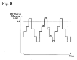
- the 360-degree difference ⁇ 360 between a large 30-degree rotation time T30 for a misfired cylinder and a small 30-degree rotation time T30 for a non-misfired cylinder is greater than the 360-degree difference ⁇ 360 between 30-degree rotation times T30 for two non-misfired cylinders.
- a peak of the 360-degree difference ⁇ 360 thus substantially corresponds to a misfired cylinder (see Fig. 6 described later).
- the CPU 24a After computation of the 360-degree difference ⁇ 360, the CPU 24a performs an engine misfire pattern identification process for identifying a misfire pattern of the engine 22 (step S120) and terminates this engine misfire detection routine.
- the engine misfire pattern identification process of this embodiment includes a single misfire identification process for identifying a single misfire pattern with only one misfired cylinder among the multiple cylinders of the engine 22 and a consecutive misfire identification process for identifying a consecutive misfire pattern with two consecutive misfired cylinders among the multiple cylinders of the engine 22, as described below in detail.
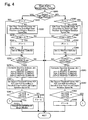
- Fig. 4 is a flowchart showing a single misfire identification routine executed by the CPU 24a of the engine ECU 24.
- the single misfire identification routine first compares the 360-degree difference ⁇ 360 with a preset first threshold value to make a tentative decision on the occurrence of a single misfire in the engine 22.
- the single misfire identification routine uses a preset second threshold value to determine whether the behavior of the 360-degree difference ⁇ 360 matches a characteristic behavior of a single misfire and makes a final decision to finally identify the occurrence of a single misfire in the engine 22 based on the result of the determination.
- the CPU 24a first specifies whether the current gear position of the transmission 60 is the Lo gear position, based on the data input at step S100 in the engine misfire detection routine (step S200).
- the current gear position of the transmission 60 may be a transient state of gear change from the Lo gear position to the Hi gear position or from the Hi gear position to the Lo gear position.
- the procedure of the embodiment specifies the transient state of gear change of the transmission 60 from the Lo gear position to the Hi gear position as the Lo gear position, while specifying the transient state of gear change of the transmission 60 from the Hi gear position to the Lo gear position as the Hi gear position.
- the CPU 24a identifies whether a single misfire tentative decision flag F1 is equal to 1 (step S210).
- the single misfire tentative decision flag F1 is set to 0 at the initial state and is set to 1 in the event of a tentative decision on the occurrence of a single misfire.
- a first threshold value A1 for a tentative decision on a single misfire in the engine 22 at the Lo gear position is set according to the engine rotation speed Ne and the specified gear position of the transmission 60 (step S220).
- the procedure of setting the first threshold value A1 in this embodiment experimentally or otherwise determines the value of the 360-degree difference ⁇ 360 in the single misfire state of the engine 22 corresponding to the engine rotation speed Ne at the Lo gear position of the transmission 60.
- the procedure refers to this experimental result and specifies and stores a variation in first threshold value A1 ensuring highly accurate detection of the single misfire state of the engine 22 against the rotation speed Ne of the engine 22 as a first threshold value setting map in the ROM 24b.
- the procedure reads the first threshold value A1 corresponding to the given gear position of the transmission 60 (the Lo gear position in this flow) and the given engine rotation speed Ne from the first threshold value setting map.
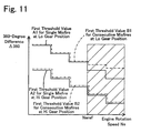
- Fig. 5 shows one example of the first threshold value setting map representing variations of first threshold values against the engine rotation speed Ne and the current gear position.
- first threshold value A2 for a tentative decision on a single misfire in the engine 22 at the Hi gear position of the transmission 60
- first threshold value B1 for a tentative decision on consecutive misfires in the engine 22 at the Lo gear position of the transmission 60
- first threshold value B2 for a tentative decision on consecutive misfires in the engine 22 at the Hi gear position of the transmission 60
- A1 for a tentative decision on a single misfire in the engine 22 at the Lo gear position of the transmission 60
- the first threshold values B1 and B2 will be described later.
- the first threshold value A1 for the tentative decision on a single misfire at the Lo gear position and the first threshold value A2 for the tentative decision on a single misfire at the Hi gear position are empirically determined to decrease with an increase in engine rotation speed Ne.
- the first threshold value A2 at the Hi gear position of the transmission 60 is empirically determined to be smaller than the first threshold value A1 at the Lo gear position of the transmission 60. Namely the smaller first threshold value is given at the higher gear position.
- the CPU 24a determines whether the 360-degree difference ⁇ 360 exceeds the first threshold value A1 (step S230). When the 360-degree difference ⁇ 360 does not exceed the first threshold value A1, a target cylinder of the single misfire identification is identified as no single-misfired cylinder. The CPU 24a thus immediately terminates this single misfire identification routine.
- the 360-degree difference ⁇ 360 exceeds the first threshold value A1
- the target cylinder of the single misfire identification is a single-misfired cylinder.
- the CPU 24a makes a tentative decision on the occurrence of a single misfire in the target cylinder and sets the value '1' to the single misfire tentative decision flag F1 (step S240).
- the target cylinder is then set to a misfired cylinder P3 (step S250).
- 'P3' represents a symbol of convenience given to a misfired cylinder for easy discrimination of the 360-degree differences ⁇ 360 of the misfired cylinder and cylinders explosively combusted before and after the misfired cylinder in a subsequent final decision of a single misfire described later.
- Fig. 6 is a chart showing a variation in 360-degree difference ⁇ 360 in the single misfire state at the Lo gear position of the transmission 60. In the chart of Fig.
- a cylinder having the 360-degree difference ⁇ 360 exceeding the first threshold value A1 is specified as the misfired cylinder P3.
- a cylinder explosively combusted immediately before the misfired cylinder P3 is shown as a pre-misfire cylinder P4.
- Cylinders explosively combusted immediately, second, and third after the misfired cylinder P3 are respectively shown as post-misfire cylinders P2, P1, and P0.
- step S260 the CPU 24a determines whether decision indexes Ja1, Ja2, and Ja3 used for the final decision of a single misfire are computable.
- the final decision of a single misfire uses the decision indexes computed from the 360-degree differences ⁇ 360 of the post-misfire cylinders explosively combusted after the misfired cylinder P3. Namely the final decision can not be made immediately after the tentative decision.
- the processing of step S260 determines whether the final decision is allowable after the tentative decision of a single misfire. When the decision indexes Ja1, Ja2, and Ja3 are not computable, the CPU 24a terminates the single misfire identification routine.
- the decision indexes Ja1, Ja2, and Ja3 are determined as computable at step S260.
- the decision indexes Ja1, Ja2, and Ja3 are actually computed (step S270).
- the decision index Ja1 represents a ratio ⁇ 360(P4)/ ⁇ 360(P3) of the 360-degree difference ⁇ 360(P4) of the pre-misfire cylinder P4 explosively combusted immediately before the misfired cylinder P3 to the 360-degree difference ⁇ 360(P3) of the misfired cylinder P3.
- the decision index Ja2 represents a ratio ⁇ 360(P2)/ ⁇ 360(P3) of the 360-degree difference ⁇ 360(P2) of the post-misfire cylinder P2 explosively combusted immediately after the misfired cylinder P3 to the 360-degree difference ⁇ 360(P3) of the misfired cylinder P3.
- the decision index Ja3 represents a ratio
- Second threshold values A12, A13, and A14 to be referred to for the final decision of a single misfire at the Lo gear position are then set according to the specified gear position and the engine rotation speed Ne (step S280).
- the second threshold value A12 represents an upper limit in a varying range of the ratio ⁇ 360(P4)/ ⁇ 360(P3) of the 360-degree difference ⁇ 360(P4) of the pre-misfire cylinder P4 explosively combusted immediately before the misfired cylinder P3 to the 360-degree difference ⁇ 360(P3) of the misfired cylinder P3 in the single misfire state at the Lo gear position.
- the second threshold value A13 represents an upper limit in a varying range of the ratio ⁇ 360(P2)/ ⁇ 360(P3) of the 360-degree difference ⁇ 360(P2) of the post-misfire cylinder P2 explosively combusted immediately after the misfired cylinder P3 to the 360-degree difference ⁇ 360(P3) of the misfired cylinder P3 in the single misfire state at the Lo gear position.
- the second threshold value A14 represents a lower limit in a varying range of the ratio
- the procedure of setting the second threshold values A12, A13, and A14 in this embodiment stores experimentally or otherwise specified variations of these second threshold values A12, A13, and A14 against the engine rotation speed Ne and the gear position (the Lo gear position in this flow) as a map in the ROM 24b and reads the second threshold values A12, A13, and A14 corresponding to the given gear position and the given engine rotation speed Ne from the map in the ROM 24b.
- step S290 the CPU 24a determines whether the computed decision indexes Ja1, Ja2, and Ja3 are respectively in the ranges defined by the second threshold values A12, A13, and A14 (step S290).
- the determination result of step S290 identifies whether the tentatively judged misfire is a single misfire at the Lo gear position of the transmission 60.
- the tentatively judged misfire is not a single misfire.
- the CPU 24a then sets 0 to the single misfire tentative decision flag F1 (step S300) and terminates the single misfire identification routine.
- the final decision is made to determine that the tentatively judged misfire is a single misfire.
- the CPU 24a then outputs the occurrence of a single misfire (step S310) and terminates the single misfire identification routine.
- the CPU 24a identifies whether the single misfire tentative decision flag F1 is equal to 1 (step S320).
- the single misfire tentative decision flag F1 is not equal to 1 but is equal to 0
- the first threshold value A2 for a tentative decision on a single misfire in the engine 22 at the Hi gear position is set according to the engine rotation speed Ne and the specified gear position of the transmission 60 (step S330).
- the procedure of setting the first threshold value A2 in this embodiment stores an empirically or otherwise specified variation in first threshold value A2 ensuring highly accurate detection of the single misfire state of the engine 22 at the Hi gear position of the transmission 60 against the engine rotation speed Ne as the first threshold value setting map of Fig. 5 in the ROM 24b.
- the procedure reads the first threshold value A2 corresponding to the given gear position of the transmission 60 (the Hi gear position in this flow) and the given engine rotation speed Ne from the first threshold value setting map.
- the first threshold value A2 is set to be smaller than the first threshold value A1.
- the threshold values used for detection of a single misfire are changed according to the gear position of the transmission 60, because of the following reason.
- the gear ratio of the rotating shaft 48 of the motor MG2 to the ring gear shaft 32a of the power distribution integration mechanism 30 linked with the crankshaft 26 of the engine 22 is varied according to the gear position of the transmission 60.
- the changed gear position may thus vary the effects of the operating conditions of the transmission 60 and the power distribution integration mechanism 30 on the crankshaft 26 of the engine 22 via the damper 28.
- the CPU 24a determines whether the 360-degree difference ⁇ 360 exceeds the first threshold value A2 (step S340). When the 360-degree difference ⁇ 360 does not exceed the first threshold value A2, the target cylinder of the single misfire identification is identified as no single-misfired cylinder. The CPU 24a thus immediately terminates this single misfire identification routine.
- the 360-degree difference ⁇ 360 exceeds the first threshold value A2
- the target cylinder of the single misfire identification is a single-misfired cylinder.
- Fig. 7 is a chart showing a variation in 360-degree difference ⁇ 360 in the single misfire state at the Hi gear position of the transmission 60.
- a cylinder having the 360-degree difference ⁇ 360 exceeding the first threshold value A2 is specified as the misfired cylinder P3.
- a cylinder explosively combusted immediately before the misfired cylinder P3 is shown as a pre-misfire cylinder P4.
- Cylinders explosively combusted immediately, second, and third after the misfired cylinder P3 are respectively shown as post-misfire cylinders P2, P1, and P0.
- the CPU 24a determines whether the decision indexes Ja1, Ja2, and Ja3 used for the final decision of a single misfire are computable (step S370) in the same manner as step S260 described above. When the decision indexes Ja1, Ja2, and Ja3 are not computable, the CPU 24a terminates the single misfire identification routine. In the course of repetition of this single misfire identification routine with identification of the single misfire tentative decision flag F1 as 1 at step S320, the decision indexes Ja1, Ja2, and Ja3 are determined as computable at step S370. In response to the computable determination, the decision indexes Ja1, Ja2, and Ja3 are actually computed (step S380) in the same manner as step S270 described above.
- Second threshold values A22, A23, and A24 to be referred to for the final decision of a single misfire at the Hi gear position are then set according to the specified gear position and the engine rotation speed Ne (step S390).
- the second threshold value A22 represents an upper limit in a varying range of the ratio ⁇ 360(P4)/ ⁇ 360(P3) of the 360-degree difference ⁇ 360(P4) of the pre-misfire cylinder P4 explosively combusted immediately before the misfired cylinder P3 to the 360-degree difference ⁇ 360(P3) of the misfired cylinder P3 in the single misfire state at the Hi gear position.
- the second threshold value A23 represents an upper limit in a varying range of the ratio ⁇ 360(P2)/ ⁇ 360(P3) of the 360-degree difference ⁇ 360(P2) of the post-misfire cylinder P2 explosively combusted immediately after the misfired cylinder P3 to the 360-degree difference ⁇ 360(P3) of the misfired cylinder P3 in the single misfire state at the Hi gear position.
- the second threshold value A24 represents a lower limit in a varying range of the ratio
- the second threshold values A22, A23, and A24 at the Hi gear position are set to be respectively smaller than the corresponding second threshold values A12, A13, and A14 at the Lo gear position.
- the procedure of setting the second threshold values A22, A23, and A24 in this embodiment stores experimentally or otherwise specified variations of these second threshold values A22, A23, and A24 against the engine rotation speed Ne and the gear position (the Hi gear position in this flow) as a map in the ROM 24b and reads the second threshold values A22, A23, and A24 corresponding to the given gear position and the given engine rotation speed Ne from the map in the ROM 24b.
- step S400 After setting the second threshold values A22, A23, and A24 according to the specified gear position and the engine rotation speed Ne, the CPU 24a determines whether the computed decision indexes Ja1, Ja2, and Ja3 are respectively in the ranges defined by the second threshold values A22, A23, and A24 (step S400).
- the determination result of step S400 identifies whether the tentatively judged misfire is a single misfire at the Hi gear position of the transmission 60.
- any of the computed decision indexes Ja1, Ja2, and Ja3 are not in the ranges defined by the second threshold values A22, A23, and A24, it is determined that the tentatively judged misfire is not a single misfire.
- the CPU 24a then sets 0 to the single misfire tentative decision flag F1 (step S410) and terminates the single misfire identification routine.
- the final decision is made to determine that the tentatively judged misfire is a single misfire.
- the CPU 24a then outputs the occurrence of a single misfire (step S310) and terminates the single misfire identification routine.
- Fig. 8 is a flowchart showing a consecutive misfire identification routine executed by the CPU 24a of the engine ECU 24.
- the consecutive misfire identification routine makes a tentative decision and a final decision to identify the occurrence of consecutive misfires in the engine 22.
- the CPU 24a first specifies whether the current gear position of the transmission 60 is the Lo gear position, based on the data input at step S100 in the engine misfire detection routine (step S500).
- the procedure of the embodiment specifies the transient state of gear change of the transmission 60 from the Lo gear position to the Hi gear position as the Lo gear position, while specifying the transient state of gear change of the transmission 60 from the Hi gear position to the Lo gear position as the Hi gear position.
- the first threshold value B1 for a tentative decision on consecutive misfires in the engine 22 at the Low gear position is set according to the engine rotation speed Ne and the specified gear position of the transmission 60 (step S510).
- the procedure of setting the first threshold value B1 in this embodiment experimentally or otherwise determines the value of the 360-degree difference ⁇ 360 in the consecutive misfire state of the engine 22 corresponding to the engine rotation speed Ne at the Lo gear position of the transmission 60.
- the procedure refers to this experimental result and specifies and stores a variation in first threshold value B1 ensuring highly accurate detection of the consecutive misfire state of the engine 22 against the rotation speed Ne of the engine 22 as a first threshold value setting map in the ROM 24b.
- the procedure reads the first threshold value B1 corresponding to the given gear position of the transmission 60 (the Lo gear position in this flow) and the given engine rotation speed Ne from the first threshold value setting map. As shown in Fig.
- the first threshold value B1 for the tentative decision on consecutive misfires at the Lo gear position and the first threshold value B2 for the tentative decision on consecutive misfires at the Hi gear position are empirically determined to decrease with an increase in engine rotation speed Ne.
- the first threshold value B2 at the Hi gear position of the transmission 60 is empirically determined to be smaller than the first threshold value B1 at the Lo gear position of the transmission 60. Namely the smaller first threshold value is given at the higher gear position.
- the first threshold value A1 for the tentative decision on a single misfire at the Lo gear position and the first threshold value B1 for the tentative decision on consecutive misfires at the Lo gear position have identical values in an engine rotation speed range of not higher than a preset rotation speed Neref.
- the first threshold value B1 is set to be greater than the first threshold value A1.
- Different values are set to the first threshold value A1 and the first threshold value B1 for engine misfire identification in the engine rotation speed range of higher than the preset rotation speed Neref, because of the following reason.
- the first threshold value A2 for the tentative decision on a single misfire at the Hi gear position and the first threshold value B2 for the tentative decision on consecutive misfires at the Hi gear position have identical values over the whole range of the engine rotation speed Ne.
- the CPU 24a After setting the first threshold value B1, the CPU 24a identifies whether a consecutive misfire tentative decision flag F2 is equal to 1 (step S520).
- the consecutive misfire tentative decision flag F2 is set to 0 at the initial state and is set to 1 in the event of a tentative decision on the occurrence of consecutive misfires.
- the CPU 24a determines whether the 360-degree difference ⁇ 360 exceeds the first threshold value B1 (step S530).
- a target cylinder of the consecutive misfire identification is identified as no consecutively-misfired cylinder. The CPU 24a thus immediately terminates this consecutive misfire identification routine.
- the CPU 24a makes a tentative decision on the occurrence of a consecutive misfire in the target cylinder and sets the value '1' to the consecutive misfire tentative decision flag F2 (step S540).
- the CPU 24a then performs a setting process of a misfired cylinder P3 (step S550).
- the consecutive misfire identification routine of this embodiment in response to detection of a no-exceeding cylinder having the 360-degree difference ⁇ 360 not exceeding the first threshold value B1 (a cylinder P2 in Fig.
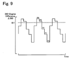
- Fig. 9 is a chart showing a variation in 360-degree difference ⁇ 360 in the consecutive misfire state at the Lo gear position of the transmission 60.
- a last cylinder having the 360-degree difference ⁇ 360 exceeding the first threshold value B1 is specified as the misfired cylinder P3.
- a cylinder explosively combusted immediately before the misfired cylinder P3 is shown as a pre-misfire cylinder P4.
- Cylinders explosively combusted immediately, second, and third after the misfired cylinder P3 are respectively shown as post-misfire cylinders P2, P1, and P0.
- step S560 the CPU 24a determines whether decision indexes Jb1, Jb2, Jb3, and Jb4 used for the final decision of consecutive misfires are computable.
- the processing of step S560 determines whether the final decision is allowable after the tentative decision of consecutive misfires, as in the similar manner to the processing of step S260 in the single misfire identification routine.
- the CPU 24a terminates the consecutive misfire identification routine.
- the decision indexes Jb1, Jb2, Jb3, and Jb4 are determined as computable at step S560. In response to the computable determination, the decision indexes Jb1, Jb2, Jb3, and Jb4 are actually computed (step S570).
- the decision index Jb1 represents a ratio ⁇ 360(P4)/ ⁇ 360(P3) of the 360-degree difference ⁇ 360(P4) of the pre-misfire cylinder P4 explosively combusted immediately before the misfired cylinder P3 to the 360-degree difference ⁇ 360(P3) of the misfired cylinder P3.
- the decision index Jb2 represents a ratio ⁇ 360(P2)/ ⁇ 360(P3) of the 360-degree difference ⁇ 360(P2) of the post-misfire cylinder P2 explosively combusted immediately after the misfired cylinder P3 to the 360-degree difference ⁇ 360(P3) of the misfired cylinder P3.
- the decision index Jb3 represents a ratio
- the decision index Jb4 represents a sum ⁇ 360(P2)+ ⁇ 360(P4) of the 360-degree difference ⁇ 360(P2) of the post-misfire cylinder P2 explosively combusted immediately after the misfired cylinder P3 and the 360-degree difference ⁇ 360(P4) of the pre-misfire cylinder P4 explosively combusted immediately before the misfired cylinder P3.
- Second threshold values B12, B13, B14, and B15 to be referred to for the final decision of consecutive misfires at the Lo gear position are then set according to the specified gear position and the engine rotation speed Ne (step S580).
- the second threshold value B12 represents an upper limit in a varying range of the ratio ⁇ 360(P4)/ ⁇ 360(P3) of the 360-degree difference ⁇ 360(P4) of the pre-misfire cylinder P4 explosively combusted immediately before the misfired cylinder P3 to the 360-degree difference ⁇ 360(P3) of the misfired cylinder P3 in the consecutive misfire state at the Lo gear position.
- the second threshold value B13 represents an upper limit in a varying range of the ratio ⁇ 360(P2)/ ⁇ 360(P3) of the 360-degree difference ⁇ 360(P2) of the post-misfire cylinder P2 explosively combusted immediately after the misfired cylinder P3 to the 360-degree difference ⁇ 360(P3) of the misfired cylinder P3 in the consecutive misfire state at the Lo gear position.
- the second threshold value B14 represents a lower limit in a varying range of the ratio
- the second threshold value B15 represents an upper limit in a varying range of the sum ⁇ 360(P2)+ ⁇ 360(P4) of the 360-degree difference ⁇ 360(P2) of the post-misfire cylinder P2 explosively combusted immediately after the misfired cylinder P3 and the 360-degree difference ⁇ 360(P4) of the pre-misfire cylinder P4 explosively combusted immediately before the misfired cylinder P3 in the consecutive misfire state at the Lo gear position.
- the procedure of setting the second threshold values B12, B13, B14, and B15 in this embodiment stores experimentally or otherwise specified variations of these second threshold values B12, B13, B14, and B15 against the engine rotation speed Ne and the gear position (the Lo gear position in this flow) as a map in the ROM 24b and reads the second threshold values B12, B13, B14, and B15 corresponding to the given gear position and the given engine rotation speed Ne from the map in the ROM 24b.
- step S590 After setting the second threshold values B12, B13, B14, and B15 according to the specified gear position and the engine rotation speed Ne, the CPU 24a determines whether the computed decision indexes Jb1, Jb2, Jb3, and Jb4 are respectively in the ranges defined by the second threshold values B12, B13, B14, and B15 (step S590).
- the determination result of step S590 identifies whether the tentatively judged misfire is consecutive misfires at the Lo gear position of the transmission 60.
- the tentatively judged misfire is not consecutive misfires.
- the CPU 24a then sets 0 to the consecutive misfire tentative decision flag F2 (step S600) and terminates the consecutive misfire identification routine.
- the final decision is made to determine that the tentatively judged misfire is consecutive misfires.
- the CPU 24a then outputs the occurrence of consecutive misfires (step S610) and terminates the consecutive misfire identification routine.
- the first threshold value B2 for a tentative decision on consecutive misfires in the engine 22 at the Hi gear position is set according to the engine rotation speed Ne and the specified gear position of the transmission 60 (step S620).
- the procedure of setting the first threshold value B2 in this embodiment experimentally or otherwise determines the value of the 360-degree difference ⁇ 360 in the consecutive misfire state of the engine 22 corresponding to the engine rotation speed Ne at the Hi gear position of the transmission 60.
- the procedure refers to this experimental result and specifies and stores a variation in first threshold value B2 ensuring highly accurate detection of the consecutive misfire state of the engine 22 against the rotation speed Ne of the engine 22 as the first threshold value setting map of Fig. 5 in the ROM 24b.
- the procedure reads the first threshold value B2 corresponding to the given gear position of the transmission 60 (the Hi gear position in this flow) and the given engine rotation speed Ne from the first threshold value setting map.
- the first threshold value B2 is set to be smaller than the first threshold value B1.
- the threshold values used for detection of consecutive misfires are changed according to the gear position of the transmission 60, because of the following reason.
- the gear ratio of the rotating shaft 48 of the motor MG2 to the ring gear shaft 32a of the power distribution integration mechanism 30 linked with the crankshaft 26 of the engine 22 is varied according to the gear position of the transmission 60.
- the changed gear position may thus vary the effects of the operating conditions of the transmission 60 and the power distribution integration mechanism 30 on the crankshaft 26 of the engine 22 via the damper 28.
- the first threshold value B2 for the tentative decision on consecutive misfires at the Hi gear position is identical with the first threshold value A2 for the tentative decision on a single misfire at the Hi gear position over the whole range of the engine rotation speed Ne.
- the CPU 24a After setting the first threshold value B2, the CPU 24a identifies whether the consecutive misfire tentative decision flag F2 is equal to 1 (step S630). When the consecutive misfire tentative decision flag F2 is not equal to 1 but is equal to 0, the CPU 24a determines whether the 360-degree difference ⁇ 360 exceeds the first threshold value B2 (step S640). When the 360-degree difference ⁇ 360 does not exceed the first threshold value B2, the target cylinder of the consecutive misfire identification is identified as no consecutively-misfired cylinder. The CPU 24a thus immediately terminates this consecutive misfire identification routine. When the 360-degree difference ⁇ 360 exceeds the first threshold value B2, on the other hand, there is a possibility that the target cylinder of the consecutive misfire identification is a consecutively-misfired cylinder.
- Fig. 10 is a chart showing a variation in 360-degree difference ⁇ 360 in the consecutive misfire state at the Hi gear position of the transmission 60.
- a last cylinder having the 360-degree difference ⁇ 360 exceeding the first threshold value B2 among at least one cylinder detected to have the 360-degree difference ⁇ 360 exceeding the first threshold value B2 is specified as the misfired cylinder P3.
- Cylinders explosively combusted immediately and second before the misfired cylinder P3 are respectively shown as pre-misfire cylinders P4 and P5. Cylinders explosively combusted immediately, second, and third after the misfired cylinder P3 are respectively shown as post-misfire cylinders P2, P1, and P0.
- pre-misfire cylinders P4 and P5. Cylinders explosively combusted immediately, second, and third after the misfired cylinder P3 are respectively shown as post-misfire cylinders P2, P1, and P0.
- the CPU 24a determines whether decision indexes Jb1, Jb2, Jb3, and Jb5 used for the final decision of consecutive misfires are computable (step S670) in the similar manner to the determination of step S560. When the decision indexes Jb1, Jb2, Jb3, and Jb5 are not computable, the CPU 24a terminates the consecutive misfire identification routine.
- the decision indexes Jb1, Jb2, Jb3, and Jb5 are determined as computable at step S670. In response to the computable determination, the decision indexes Jb1, Jb2, Jb3, and Jb5 are actually computed (step S680).
- the decision index Jb1 represents a ratio ⁇ 360(P4)/ ⁇ 360(P3) of the 360-degree difference ⁇ 360(P4) of the pre-misfire cylinder P4 explosively combusted immediately before the misfired cylinder P3 to the 360-degree difference ⁇ 360(P3) of the misfired cylinder P3.
- the decision index Jb2 represents a ratio ⁇ 360(P2)/ ⁇ 360(P3) of the 360-degree difference ⁇ 360(P2) of the post-misfire cylinder P2 explosively combusted immediately after the misfired cylinder P3 to the 360-degree difference ⁇ 360(P3) of the misfired cylinder P3.
- the decision index Jb3 represents a ratio
- the decision index Jb5 represents a ratio ⁇ 360(P5)/ ⁇ 360(P3) of the 360-degree difference ⁇ 360(P5) of the pre-misfire cylinder P5 explosively combusted second before the misfired cylinder P3 to the 360-degree difference ⁇ 360(P3) of the misfired cylinder P3.
- Second threshold values B22, B23, B24, B25, and B26 to be referred to for the final decision of consecutive misfires at the Hi gear position in the judgment pattern X are then set according to the specified gear position and the engine rotation speed Ne (step S690).
- the second threshold values B22 and B23 respectively represent a lower limit and an upper limit in a varying range of the ratio ⁇ 360(P4)/ ⁇ 360(P3) of the 360-degree difference ⁇ 360(P4) of the pre-misfire cylinder P4 explosively combusted immediately before the misfired cylinder P3 to the 360-degree difference ⁇ 360(P3) of the misfired cylinder P3 in the consecutive misfire state at the Hi gear position.
- the second threshold value B24 represents an upper limit in a varying range of the ratio ⁇ 360(P2)/ ⁇ 360(P3) of the 360-degree difference ⁇ 360(P2) of the post-misfire cylinder P2 explosively combusted immediately after the misfired cylinder P3 to the 360-degree difference ⁇ 360(P3) of the misfired cylinder P3 in the consecutive misfire state at the Hi gear position.
- the second threshold value B25 represents a lower limit in a varying range of the ratio
- the second threshold value B26 represents an upper limit in a varying range of the ratio ⁇ 360(P5)/ ⁇ 360(P3) of the 360-degree difference ⁇ 360(P5) of the pre-misfire cylinder P5 explosively combusted second before the misfired cylinder P3 to the 360-degree difference ⁇ 360(P3) of the misfired cylinder P3 in the consecutive misfire state at the Hi gear position.
- the procedure of setting the second threshold values B22, B23, B24, B25, and B26 in this embodiment stores experimentally or otherwise specified variations of these second threshold values B22, B23, B24, B25, and B26 against the engine rotation speed Ne and the gear position (the Hi gear position in this flow) as a map in the ROM 24b and reads the second threshold values B22, B23, B24, B25, and B26 corresponding to the given gear position and the given engine rotation speed Ne from the map in the ROM 24b.
- Second threshold values B27, B28, B29, B30, and B31 to be referred to for the final decision of consecutive misfires at the Hi gear position in the judgment pattern Y are then set according to the specified gear position and the engine rotation speed Ne (step S700).
- the second threshold values B27 and B28 respectively represent a lower limit and an upper limit in a varying range of the ratio ⁇ 360(P4)/ ⁇ 360(P3) of the 360-degree difference ⁇ 360(P4) of the pre-misfire cylinder P4 explosively combusted immediately before the misfired cylinder P3 to the 360-degree difference ⁇ 360(P3) of the misfired cylinder P3 in the consecutive misfire state at the Hi gear position.
- the second threshold values B29 and B30 respectively represent a lower limit and an upper limit in a varying range of the ratio ⁇ 360(P2)/ ⁇ 360(P3) of the 360-degree difference ⁇ 360(P2) of the post-misfire cylinder P2 explosively combusted immediately after the misfired cylinder P3 to the 360-degree difference ⁇ 360(P3) of the misfired cylinder P3 in the consecutive misfire state at the Hi gear position.
- the second threshold value B31 represents a lower limit in a varying range of the ratio
- the procedure of setting the second threshold values B27, B28, B29, B30, and B31 in this embodiment stores experimentally or otherwise specified variations of these second threshold values B27, B28, B29, B30, and B31 against the engine rotation speed Ne and the gear position (the Hi gear position in this flow) as a map in the ROM 24b and reads the second threshold values B27, B28, B29, B30, and B31 corresponding to the given gear position and the given engine rotation speed Ne from the map in the ROM 24b.
- step S710 After setting the second threshold values B27 through B31 according to the specified gear position and the engine rotation speed Ne, the CPU 24a determines whether the computed decision indexes Jb1, Jb2, Jb3, and Jb5 are respectively in the ranges defined by the second threshold values B22 through B26 (step S710).
- the determination result of step S710 identifies, whether the tentatively judged misfire is consecutive misfires in the judgment pattern X at the Hi gear position of the transmission 60.
- it is determined that the tentatively judged misfire is not consecutive misfires in the judgment pattern X.
- the CPU 24a subsequently determines whether the computed decision indexes Jb1, Jb2, Jb3, and Jb5 are respectively in the ranges defined by the second threshold values B27 through B31 (step S720).
- the determination result of step S720 identifies whether the tentatively judged misfire is consecutive misfires in the judgment pattern Y at the Hi gear position of the transmission 60.
- the CPU 24a sets 0 to the consecutive misfire tentative decision flag F2 (step S730) and terminates the consecutive misfire identification routine.
- the final decision is made to determine that the tentatively judged misfire is consecutive misfires.
- the CPU 24a then outputs the occurrence of consecutive misfires (step S610) and terminates the consecutive misfire identification routine.
- the engine misfire detection process calculates the 30-degree rotation times T30 corresponding to the crank angles CA of the engine 22, computes the 360-degree differences ⁇ 360 from the 30-degree rotation times T30, sets the threshold values (first threshold values A1 and A2, first threshold values B1 and B, second threshold values A12 through A24, and second threshold values B12 through B31) to be referred for identification of the engine misfire pattern according to the gear position of the transmission 60, and identifies the engine misfire pattern based on the computed 360-degree differences ⁇ 360 and the set threshold values.
- the change gear ratio of the rotating shaft 48 of the motor MG2 to the ring gear shaft 32a mechanically linked with the crankshaft 26 of the engine 22 is varied according to the gear position of the transmission 60.
- the changed gear position may thus vary the effects of the operating conditions of the motor MG2 and the transmission 60 on the crankshaft 26 of the engine 22 via the damper 28.
- the threshold values used for detection of the engine misfire are set according to the gear position of the transmission 60. This arrangement of the embodiment ensures accurate detection of a misfire in the engine 22.
- the smaller values are set to the first threshold values A1 and A2 for the tentative decision on a single misfire and to the first threshold values B1 and B2 for the tentative decision on consecutive misfires.
- the threshold values used for detection of engine misfires are adequately set corresponding to the gear position of the transmission 60.
- the first threshold values A1 and A2 and the first threshold values B1 and B2 are set to decrease with an increase in rotation speed Ne of the engine 22.
- the threshold values used for detection of engine misfires are adequately set corresponding to the rotation speed Ne of the engine 22.
- the tentative decision on engine misfire is made when the 360-degree difference ⁇ 360 is greater than the corresponding one of the first threshold values A1, A2 and the first threshold values B1 and B2.
- the final decision on the engine misfire is made when the 360-degree differences ⁇ 360 are in the ranges defined by the corresponding ones of the second threshold values A12 through A24 and the second threshold values B12 through B31.
- the engine misfire detection process of this embodiment makes the tentative decision and the final decision on the engine misfire in the above manner and thus desirably enhances the accuracy of detection of the engine misfire.
- the first threshold values and the second threshold values used respectively for the tentative decision and for the final decision on the engine misfire are set according to the gear position of the transmission 60. This further enhances the accuracy of detection of the engine misfire.
- the single misfire identification process at the Lo gear position of the transmission 60 makes the final decision on the occurrence of a single misfire in the engine 22, based on the result of the determination whether the decision indexes Ja1, Ja2, and Ja3 are in the ranges defined by the second threshold values A12, A13, and A14.
- any two of these three decision indexes Ja1, Ja2, and Ja3 may be used for the final decision on a single misfire.
- any one of these three decision indexes Ja1, Ja2, and Ja3 may be used for the final decision on a single misfire.
- Decision indexes different from these decision indexes Ja1, Ja2, and Ja3 may alternatively be used for the final decision on a single misfire.
- Such modifications are also applicable to the single misfire identification process at the Hi gear position of the transmission 60, as well as to the consecutive misfire identification process at the Lo gear position and at the Hi gear position of the transmission 60.
- the engine misfire pattern identification process of the embodiment uses the first threshold value setting map of Fig. 5 to set the first threshold values linearly varying in proportion to the engine rotation speed Ne.
- the first threshold value setting map of Fig. 5 may be replaced by another first threshold value setting map shown in Fig. 11 that sets the first threshold values varying stepwise.
- the hybrid vehicle 20 of the embodiment uses the transmission 60 having the two different gear positions, that is, the Lo gear position and the Hi gear position.
- the technique of the invention is also applicable to a transmission having three or more different gear positions.
- threshold values used for detection of engine misfires may be set corresponding to each of the multiple different gear positions.
- the above embodiment regards the hybrid vehicle 20 equipped with the six-cylinder engine 22.
- the technique of the invention is also applicable to hybrid vehicles equipped with engines having various numbers of cylinders, for example, a hybrid vehicle equipped with a four-cylinder engine and a hybrid vehicle equipped with an eight-cylinder engine.
- the first threshold values used for the tentative decision on the engine misfire and the second threshold values used for the final decision on the engine misfire are empirically determined according to the gear ratio of the transmission 60 in each of such hybrid vehicles.
- the technique of the invention is applied to both the detection of a single misfire and the detection of consecutive misfires.
- the technique of the invention may be applied to only the detection of a single misfire or to only the detection of consecutive misfires.
- the technique of the invention is also applicable to detection of another engine misfire pattern other than the single misfire and the consecutive misfires, for example, intermittent misfires where two cylinders across one combusted cylinder are misfired among multiple cylinders.
- the engine misfire detection process of the embodiment detects the engine misfire, based on the 360-degree differences ⁇ 360 calculated from the 30-degree rotation time T30.
- the 360-degree differences ⁇ 360 is, however, not essential for detection of engine misfire.
- a 120-degree difference ⁇ 120 given as a difference between the currently input 30-degree rotation time T30 and a previous 30-degree rotation time T30 input 120 degrees before or a 720-degree difference ⁇ 720 given as a difference between the currently input 30-degree rotation time T30 and a previous 30-degree rotation time T30 input 720 degrees before may be used for the same purpose.
- the 30-degree rotation time T30 may be used directly for detection of engine misfire.
- the rotation speed of the crankshaft 26 may be used as a parameter of the 30-degree rotation time T30.
- the technique of the invention is not restricted to the engine misfire detection apparatus for the engine 22 mounted on hybrid vehicles but is also applicable to the engine misfire detection apparatus for the engine 22 mounted on various moving bodies other than motor vehicles, as well as the engine misfire detection apparatus for the engine 22 built in stationary equipment, such as construction machinery.
- Another application of the invention is an engine misfire detection method for detecting misfires of the engine 22.
- the technique of the invention is preferably applicable to the motor vehicle-related industries including automobiles, buses, and motortrucks, as well as to transport vehicle-related industries including train cars, boats and ships, and aircraft.
Abstract
Description
- The present invention relates to an engine misfire detection apparatus, a hybrid vehicle equipped with the engine misfire detection, and an engine misfire detection method.
- One proposed structure of an engine misfire detection apparatus detects a misfire of an engine in a power output apparatus, based on an output torque command value of a first motor generator (see, for example, Patent Document 1). The power output apparatus includes the engine, a planetary gear mechanism having a carrier and a ring gear respectively linked with a crankshaft of the engine and with an axle, a first motor generator linked with a sun gear of the planetary gear mechanism, and the second motor generator linked with the axle. In the power output apparatus, the output torque of the first motor generator is varied in synchronism with the explosive combustion timing of the engine, in order to control the potential vibrations due to the torque pulsation of the engine. The occurrence of an engine misfire is detected in response to a significant fall of the output torque command value from a previous value. In another proposed structure of the power output apparatus, the second motor generator is linked with the axle via a transmission (see, for example, Patent Document 2).
- Patent Document 1: Japanese Patent Laid-Open Gazette No.
2000-240501 - Patent Document 2: Japanese Patent Laid-Open Gazette No.
2005-170317 - In the power output apparatus disclosed in
Patent Document 2, the gear ratio of a rotating shaft of the second motor generator to a driveshaft linked with the crankshaft or output shaft of the engine is varied according to the gear position of the transmission. The changed gear position may thus vary the effects of the operating conditions of the transmission, the driveshaft, and the planetary gear mechanism on the crankshaft of the engine. The engine misfire detection apparatus disclosed inPatent Document 1 does not take into account the varying effects according to the gear position of the transmission for detection of an engine misfire. There is accordingly a demand for ensuring accurate detection of an engine misfire in a power output apparatus including a transmission. - In an engine misfire detection apparatus for detection of a misfire in an internal combustion engine that is included in a power output apparatus having a transmission mechanism linked with both a motor and a driveshaft, a hybrid vehicle equipped with the engine misfire detection apparatus, and a corresponding engine misfire detection method, there is a need of ensuring accurate detection of an engine misfire.
- In order to satisfy at least part of the above and the other related requirements, the engine misfire detection apparatus, the hybrid vehicle equipped with the engine misfire detection apparatus, and the corresponding engine misfire detection method have the configurations discussed below.
- According to one aspect, the present invention is directed to an engine misfire detection apparatus for detection of a misfire in a multi-cylinder internal combustion engine included in a power output apparatus, where the power output apparatus includes the multi-cylinder internal combustion engine having a crankshaft mechanically linked with a driveshaft, a motor that outputs power to the driveshaft, and a transmission mechanism that transmits power between a rotating shaft of the motor and the driveshaft with a change in gear position. The engine misfire detection apparatus includes: a rotational position detection unit that detects a rotational position of the crankshaft of the internal combustion engine;
a unit angle rotation time computation module that computes a unit angle rotation time required for rotation of an output shaft of the internal combustion engine by every predetermined unit rotation angle according to the detected rotational position;
a threshold value setting module that sets a specific threshold value used for detection of an engine misfire according to a gear position of the transmission mechanism; and
an engine misfire detection module that detects an engine misfire based on the computed unit angle rotation times and the set specific threshold value. - The engine misfire detection apparatus of the invention detects the rotational position of the crankshaft of the internal combustion engine, computes the unit angle rotation time required for rotation of the output shaft of the internal combustion engine by every predetermined unit rotation angle according to the detected rotational position, sets the specific threshold value used for detection of an engine misfire according to the gear position of the transmission mechanism, and detects an engine misfire based on the computed unit angle rotation times and the set specific threshold value. The change gear ratio of the rotating shaft of the motor to the driveshaft mechanically linked with the crankshaft of the internal combustion engine is varied according to the gear position of the transmission mechanism. The changed gear position may thus vary the effects of the operating conditions of the motor and the transmission mechanism on the crankshaft of the internal combustion engine. The specific threshold value used for detection of the engine misfire is set according to the gear position of the transmission mechanism. This arrangement ensures accurate detection of a misfire in the internal combustion engine.
- In one aspect of the engine misfire detection apparatus of the invention, the threshold value setting module sets a smaller value to the specific threshold value at a higher gear position of the transmission mechanism. The engine misfire detection apparatus of this aspect adequately sets the specific threshold value used for detection of the engine misfire according to the gear position of the transmission mechanism. In another aspect of the engine misfire detection apparatus of the invention, the threshold value setting module sets the specific threshold value to decrease with an increase in rotation speed of the internal combustion engine. The engine misfire detection apparatus of this aspect adequately sets the specific threshold value used for detection of the engine misfire according to the rotation speed of the internal combustion engine. The threshold value setting module may estimate the rotation speed of the internal combustion engine according to the rotational position of the crankshaft detected by the rotational position detection unit.
- In one preferable embodiment of the engine misfire detection apparatus of the invention, the threshold value setting module sets a first threshold value and a second threshold value according to the gear position of the transmission mechanism. The engine misfire detection module makes a tentative decision on an engine misfire when any of the computed unit angle rotation times is greater than the first threshold value. After the tentative decision on the engine misfire, the engine misfire detection module specifies an object unit angle rotation time that is greater than the first threshold value among the computed unit angle rotation times and makes a final decision on the engine misfire when a ratio of a unit angle rotation time of a different cylinder, which is different from a target cylinder corresponding to the specified object unit angle rotation time, to the specified object unit angle rotation time is in a range defined by the second threshold value. The engine misfire detection apparatus of this embodiment makes the tentative decision and the final decision on the engine misfire in this manner and thus desirably enhances the accuracy of detection of the engine misfire. The first threshold value and the second threshold value respectively used for the tentative decision and for the final decision on the engine misfire are set according to the gear position of the transmission mechanism. This further enhances the accuracy of detection of the engine misfire.
- In one aspect of the engine misfire detection apparatus of the above embodiment, when a rotation speed of the internal combustion engine is out of a predetermined range, the threshold value setting module sets an identical value to the first threshold value used for detection of an engine misfire in a preset first misfire pattern and to the first threshold value used for detection of an engine misfire in a preset second misfire pattern. When the rotation speed of the internal combustion engine is within the predetermined range, the threshold value setting module sets different values to the first threshold value used for detection of the engine misfire in the preset first misfire pattern and to the first threshold value used for detection of the engine misfire in the preset second misfire pattern. The engine misfire detection module detects the engine misfire in the preset first misfire pattern based on the computed unit angle rotation times and the set first threshold value used for detection of the engine misfire in the preset first misfire pattern, while detecting the engine misfire in the preset second misfire pattern based on the computed unit angle rotation times and the set first threshold value used for detection of the engine misfire in the preset second misfire pattern. When the rotation speed of the internal combustion engine is out of the predetermined range, identical values are set to the first threshold value for the first misfire pattern and to the first threshold value for the second misfire pattern. This desirably simplifies the detection of the engine misfire. When the rotation speed of the internal combustion engine is within the predetermined range, on the other hand, different values are set to the first threshold value for the first misfire pattern and to the first threshold value for the second misfire pattern. This desirably enhances the accuracy of detection of the engine misfire. In the engine misfire detection apparatus of this aspect, the threshold value setting module may set a first threshold value for a single misfire used for detection of an engine misfire in a single misfire pattern where only one cylinder among the multiple cylinders is misfired as the first threshold value used for detection of the engine misfire in the preset first misfire pattern. The threshold value setting module may set a first threshold value for consecutive misfires used for detection of an engine misfire in a consecutive misfire pattern where two consecutive cylinders among the multiple cylinders are misfired as the first threshold value used for detection of the engine misfire in the preset second misfire pattern.
- One preferable structure of the power output apparatus, to which the engine misfire detection apparatus of the invention is applied, has: a three shaft-type power input output mechanism that is linked to three shafts, an output shaft of the internal combustion engine, the driveshaft, and a third shaft, and inputs and outputs power from and to a residual one shaft based on powers input from and output to any two shafts among the three shafts; and a generator that inputs and outputs power from and to the third shaft.
- The present invention is also directed to a hybrid vehicle that is equipped with a power output apparatus and with the engine misfire detection apparatus having any of the arrangement described above for detection of a misfire in a multi-cylinder internal combustion engine included in a power output apparatus. The power output apparatus includes: the multi-cylinder internal combustion engine having a crankshaft mechanically linked with a driveshaft; a motor that outputs power to the driveshaft; and a transmission mechanism that transmits power between a rotating shaft of the motor and the driveshaft with a change in gear position. As discussed previously, the engine misfire detection apparatus enables accurate detection of a misfire in the internal combustion engine included in the power output apparatus, which has the transmission mechanism linked with both the motor and the driveshaft. The hybrid vehicle of the invention equipped with this engine misfire detection apparatus thus exerts the similar effects.
- According to another aspect, the present invention is directed to an engine misfire detection method for detecting a misfire in a multi-cylinder internal combustion engine included in a power output apparatus, where the power output apparatus includes the multi-cylinder internal combustion engine having a crankshaft mechanically linked with a driveshaft, a motor that outputs power to the driveshaft, and a transmission mechanism that transmits power between a rotating shaft of the motor and the driveshaft with a change in gear position. The engine misfire detection method includes:
- detecting a rotational position of the crankshaft of the internal combustion engine;
- computing a unit angle rotation time required for rotation of an output shaft of the internal combustion engine by every predetermined unit rotation angle according to the detected rotational position;
- setting a specific threshold value used for detection of an engine misfire according to a gear position of the transmission mechanism; and
- detecting an engine misfire based on the computed unit angle rotation times and the set specific threshold value.
- The engine misfire detection method of the invention detects the rotational position of the crankshaft of the internal combustion engine, computes the unit angle rotation time required for rotation of the output shaft of the internal combustion engine by every predetermined unit rotation angle according to the detected rotational position, sets the specific threshold value used for detection of an engine misfire according to the gear position of the transmission mechanism, and detects an engine misfire based on the computed unit angle rotation times and the set specific threshold value. The change gear ratio of the rotating shaft of the motor to the driveshaft mechanically linked with the crankshaft of the internal combustion engine is varied according to the gear position of the transmission mechanism. The changed gear position may thus vary the effects of the operating conditions of the motor and the transmission mechanism on the crankshaft of the internal combustion engine. The specific threshold value used for detection of the engine misfire is set according to the gear position of the transmission mechanism. This arrangement ensures accurate detection of a misfire in the internal combustion engine. The engine misfire detection method of the invention may adopt any of the diverse arrangements of the engine misfire detection apparatus described above. The engine misfire detection method may have any additional steps actualizing the additional functions of the engine misfire detection apparatus described above.
-
-
Fig. 1 schematically illustrates the configuration of ahybrid vehicle 20 in one embodiment of the invention; -
Fig. 2 schematically illustrates the structure of atransmission 60; -
Fig. 3 is a flowchart showing an engine misfire detection routine executed by anengine ECU 24; -
Fig. 4 is a flowchart showing a single misfire identification routine; -
Fig. 5 shows one example of a first threshold value setting map representing variations of first threshold values against the engine rotation speed Ne and the current gear position; -
Fig. 6 is a chart showing a variation in 360-degree difference Δ360 in a single misfire state at a Lo gear position of thetransmission 60; -
Fig. 7 is a chart showing a variation in 360-degree difference Δ360 in the single misfire state at a Hi gear position of thetransmission 60; -
Fig. 8 is a flowchart showing a consecutive misfire identification routine; -
Fig. 9 is a chart showing a variation in 360-degree difference Δ360 in a consecutive misfire state at the Lo gear position of thetransmission 60; -
Fig. 10 is a chart showing a variation in 360-degree difference Δ360 in the consecutive misfire state at the Hi gear position of thetransmission 60; and -
Fig. 11 shows another example of the first threshold value setting map representing variations of the first threshold values against the engine rotation speed Ne and the current gear position. - One mode of carrying out the invention is described below as a preferred embodiment with reference to the accompanied drawings.
-
Fig. 1 schematically illustrates the configuration of ahybrid vehicle 20 equipped with an engine misfire detection apparatus for internal combustion engine in one embodiment of the invention. As illustrated, thehybrid vehicle 20 of the embodiment includes anengine 22, a three shaft-type powerdistribution integration mechanism 30 that is linked to acrankshaft 26 or an output shaft of theengine 22 via adamper 28 as a torsional element, a motor MG1 that is linked to the powerdistribution integration mechanism 30 and has power generation capability, atransmission 60 that is attached to aring gear shaft 32a or a driveshaft connected to the powerdistribution integration mechanism 30, a motor MG2 that is linked with thetransmission 60, and a hybridelectronic control unit 70 that controls the operations of the wholehybrid vehicle 20. - The
engine 22 is a six-cylinder internal combustion engine that consumes a hydrocarbon fuel, such as gasoline or light oil, to output power. An engine electronic control unit (hereafter referred to as engine ECU) 24 inputs signals representing the operating conditions of theengine 22 from various sensors and performs operation control of theengine 22 including fuel injection control, ignition control, and intake air flow regulation. Theengine ECU 24 is constructed as a microprocessor including aCPU 24a, aROM 24b that stores processing programs, aRAM 24c that temporarily stores data, input and output ports (not shown), and a communication port (not shown). Theengine ECU 24 inputs signals from various sensors that measure and detect the operating conditions of theengine 22, for example, a crank position from a crankposition sensor 26a detected as the rotational position of thecrankshaft 26. Theengine ECU 24 communicates with the hybridelectronic control unit 70. Theengine ECU 24 controls the operations of theengine 22 in response to control signals input from the hybridelectronic control unit 70, while outputting data regarding the operating conditions of theengine 22 to the hybridelectronic control unit 70 according to the requirements. The engine misfire detection apparatus for the internal combustion engine is mainly attained by theengine ECU 24 in this embodiment. - The power
distribution integration mechanism 30 includes asun gear 31 as an external gear, aring gear 32 as an internal gear arranged concentrically with thesun gear 31, multiple pinion gears 33 engaging with thesun gear 31 and with thering gear 32, and acarrier 34 holding the multiple pinion gears 33 to allow both their revolutions and their rotations on their axes. The powerdistribution integration mechanism 30 is thus constructed as a planetary gear mechanism including thesun gear 31, thering gear 32, and thecarrier 34 as rotational elements of differential motions. Thecarrier 34, thesun gear 31, and thering gear 32 of the powerdistribution integration mechanism 30 are respectively linked to thecrankshaft 26 of theengine 22, to the motor MG1, and to the reduction gear 35 via thering gear shaft 32a. When the motor MG1 functions as a generator, the power of theengine 22 input via thecarrier 34 is distributed to thesun gear 31 and to thering gear 32 according to their gear ratio. When the motor MG1 functions as a motor, on the other hand, the power of theengine 22 input via thecarrier 34 is integrated with the power of the motor MG1 input via thesun gear 31 and is output to thering gear 32. The power output to thering gear 32 is transmitted from thering gear shaft 32a through agear mechanism 37 and adifferential gear 38 and is eventually output to drivewheels hybrid vehicle 20. - The motors MG1 and MG2 are constructed as known synchronous motor generators that may be actuated both as a generator and as a motor. The motors MG1 and MG2 transmit electric powers to and from a battery 50 via
inverters 41 and 42.Power lines 54 connecting the battery 50 with theinverters 41 and 42 are structured as common positive bus and negative bus shared by theinverters 41 and 42. Such connection enables electric power generated by one of the motors MG1 and MG2 to be consumed by the other motor MG2 or MG1. The battery 50 may thus be charged with surplus electric power generated by either of the motors MG1 and MG2, while being discharged to supplement insufficient electric power. The battery 50 is neither charged nor discharged upon the balance of the input and output of electric powers between the motors MG1 and MG2. The operations of both the motors MG1 and MG2 are controlled by a motor electronic control unit (hereafter referred to as motor ECU) 40. Themotor ECU 40 inputs signals required for controlling the operations of the motors MG1 and MG2, for example, signals representing rotational positions of rotors in the motors MG1 and MG2 from rotationalposition detection sensors motor ECU 40 outputs switching control signals to theinverters 41 and 42. Themotor ECU 40 establishes communication with the hybridelectronic control unit 70 to control the operations of the motors MG1 and MG2 in response to control signals input from the hybridelectronic control unit 70 and to output data regarding the operating conditions of the motors MG1 and MG2 to the hybridelectronic control unit 70 according to the requirements. - The
transmission 60 functions to connect and disconnect arotating shaft 48 of the motor MG2 with and from thering gear shaft 32a. In the connection state, thetransmission 60 reduces the rotation speed of therotating shaft 48 of the motor MG2 at two different reduction gear ratios and transmits the reduced rotation speed to thering gear shaft 32a. One typical structure of thetransmission 60 is shown inFig. 2 . Thetransmission 60 shown inFig. 2 has a double-pinionplanetary gear mechanism 60a, a single-pinionplanetary gear mechanism 60b, and two brakes B1 and B2. The double-pinionplanetary gear mechanism 60a includes asun gear 61 as an external gear, aring gear 62 as an internal gear arranged concentrically with thesun gear 61, multiplefirst pinion gear 63a engaging with thesun gear 61, multiple second pinion gears 63b engaging with the multiple first pinion gears 63a and with thering gear 62, and acarrier 64 coupling the multiple first pinion gears 63a with the multiple second pinion gears 63b to allow both their revolutions and their rotations on their axes. The engagement and the release of the brake B1 stop and allow the rotation of thesun gear 61. The single-pinionplanetary gear mechanism 60b includes asun gear 65 as an external gear, aring gear 66 as an internal gear arranged concentrically with thesun gear 65, multiple pinion gears 67 engaging with thesun gear 65 and with thering gear 66, and acarrier 68 holding the multiple pinion gears 67 to allow both their revolutions and their rotations on their axes. Thesun gear 65 and thecarrier 68 of the single-pinionplanetary gear mechanism 60b are respectively connected to therotating shaft 48 of the motor MG2 and to thering gear shaft 32a. The engagement and the release of the brake B2 stop and allow the rotation of thering gear 66. The double-pinionplanetary gear mechanism 60a and the single-pinionplanetary gear mechanism 60b are coupled with each other via linkage of the respective ring gears 62 and 66 and linkage of therespective carriers transmission 60, the combination of the released brakes B1 and B2 disconnects the rotatingshaft 48 of the motor MG2 from thering gear shaft 32a. The combination of the released brake B1 and the engaged brake B2 reduces the rotation of therotating shaft 48 of the motor MG2 at a relatively large reduction gear ratio and transmits the largely reduced rotation to thering gear shaft 32a. This state is hereafter expressed as Lo gear position. The combination of the engaged brake B1 and the released brake B2 reduces the rotation of therotating shaft 48 of the motor MG2 at a relatively small reduction gear ratio and transmits the slightly reduced rotation to thering gear shaft 32a. This state is hereafter expressed as Hi gear position. The combination of the engaged brakes B1 and B2 prohibits the rotations of therotating shaft 48 and thering gear shaft 32a. In the structure of the embodiment, the brakes B1 and B2 are engaged and released by regulating hydraulic pressures applied to the brakes B1 and B2 with hydraulic actuators (not shown). - The battery 50 is under control and management of a battery electronic control unit (hereafter referred to as battery ECU) 52. The
battery ECU 52 inputs signals required for management and control of the battery 50, for example, an inter-terminal voltage from a voltage sensor (not shown) located between terminals of the battery 50, a charge-discharge current from a current sensor (not shown) located in thepower line 54 connecting with an output terminal of the battery 50, and a battery temperature from a temperature sensor (not shown) attached to the battery 50. Thebattery ECU 52 outputs data regarding the operating conditions of the battery 50 by communication to the hybridelectronic control unit 70 according to the requirements. Thebattery ECU 52 computes a remaining charge level or current state of charge (SOC) of the battery 50 from integration of the charge-discharge current measured by the current sensor, for the purpose of management and control of the battery 50. - The hybrid
electronic control unit 70 is constructed as a microprocessor including aCPU 72, aROM 74 that stores processing programs, aRAM 76 that temporarily stores data, input and output ports (not shown), and a communication port (not shown). The hybridelectronic control unit 70 receives, via its input port, an ignition signal from anignition switch 80, a gearshift position SP or a current setting position of agearshift lever 81 from agearshift position sensor 82, an accelerator opening Acc or the driver's depression amount of anaccelerator pedal 83 from an acceleratorpedal position sensor 84, a brake pedal position BP or the driver's depression amount of abrake pedal 85 from a brakepedal position sensor 86, and a vehicle speed V from avehicle speed sensor 88. The hybridelectronic control unit 70 outputs, via its output port, driving signals to the actuators (not shown) to operate and control the brakes B1 and B2 included in thetransmission 60. The hybridelectronic control unit 70 establishes communication with theengine ECU 24, themotor ECU 40, and thebattery ECU 52 via its communication port to receive and send the diversity of control signals and data from and to theengine ECU 24, themotor ECU 40, and thebattery ECU 52, as mentioned above. - The
hybrid vehicle 20 of the embodiment constructed as described above sets a torque demand to be output to thering gear shaft 32a or the driveshaft, based on the vehicle speed V and the accelerator opening Acc corresponding to the driver's depression amount of theaccelerator pedal 83. Theengine 22 and the motors MG1 and MG2 are controlled to be driven at efficient drive points, in order to ensure output of a power demand equivalent to the preset torque demand to thering gear shaft 32a. When the vehicle speed V exceeds a predetermined speed, for example, 60 km/h or 80 km/h, to require a Lo-to-Hi gear change, the hybridelectronic control unit 70 changes the brake conditions from the combination of the released brake B1 and the engaged brake B2 to the combination of the engaged brake B1 and the released brake B2. When the vehicle speed V decreases to or below the predetermined speed to require a Hi-to-Lo gear change, on the other hand, the hybridelectronic control unit 70 changes the brake conditions from the combination of the engaged brake B1 and the released brake B2 to the combination of the released brake B1 and the engaged brake B2. There are several drive control modes of theengine 22 and the motors MG1 and MG2. In a torque conversion drive mode, while theengine 22 is driven and controlled to output a required level of power corresponding to the power demand, the motors MG1 and MG2 are driven and controlled to enable all the output power of theengine 22 to be subjected to torque conversion by the powerdistribution integration mechanism 30 and the motors MG1 and MG2 and to be output to thering gear shaft 32a. In a charge-discharge drive mode, theengine 22 is driven and controlled to output a required level of power corresponding to the sum of the power demand and electric power used to charge the battery 50 or discharged from the battery 50. The motors MG1 and MG2 are driven and controlled to enable all or part of the output power of theengine 22, which is equivalent to the power demand with charge or discharge of the battery 50, to be subjected to torque conversion by the powerdistribution integration mechanism 30 and the motors MG1 and MG2 and to be output to thering gear shaft 32a. In a motor drive mode, the motor MG2 is driven and controlled to ensure output of a required level of power corresponding to the power demand to thering gear shaft 32a, while theengine 22 stops its operation. - The description regards a series of operations to detect a misfire in any of the cylinders of the
engine 22 mounted on thehybrid vehicle 20 of the embodiment constructed as described above.Fig. 3 is an engine misfire detection routine executed by theengine ECU 24. This engine misfire detection routine is performed repeatedly at preset time intervals. - In the engine misfire detection routine, the
CPU 24a of theengine ECU 24 first inputs a 30-degree rotation time T30 computed as a time required for a 30-degree rotation of thecrankshaft 26, an engine rotation speed Ne, and a current speed or gear position of the transmission 60 (step S100). The 30-degree rotation time T30 is computed by a T30 computation routine (not shown). The T30 computation routine successively inputs the time of each 30-degree rotation of a crank angle CA detected by thecrank position sensor 26a and calculates a difference between the currently input time for a current 30-degree rotation of the crank angle CA and the previously input time for a previous 30-degree rotation of the crank angle CA to compute the 30-degree rotation time T30. The rotation speed Ne of theengine 22 is computed based on the signal output from thecrank position sensor 26a attached to thecrankshaft 26. The speed or gear position of thetransmission 60 is identified based on the engagement-release conditions of the brakes B1 and B2 detected by sensors provided for the brakes B1 and B2 and is input from the hybridelectronic control unit 70 by communication. - The
CPU 24a subsequently computes a 360-degree difference Δ360 of the input 30-degree rotation time T30 (step S110). The 360-degree difference Δ360 of the 30-degree rotation time T30 is given as a difference between the currently input 30-degree rotation time T30 and a previous 30-degree rotationtime T30 input 360 degrees before. In the six-cylinder engine, explosive combustion of the air-fuel mixture takes place at the crank angle CA of every 120 degrees. The 360-degree difference Δ360 between a large 30-degree rotation time T30 for a misfired cylinder and a small 30-degree rotation time T30 for a non-misfired cylinder is greater than the 360-degree difference Δ360 between 30-degree rotation times T30 for two non-misfired cylinders. A peak of the 360-degree difference Δ360 thus substantially corresponds to a misfired cylinder (seeFig. 6 described later). After computation of the 360-degree difference Δ360, theCPU 24a performs an engine misfire pattern identification process for identifying a misfire pattern of the engine 22 (step S120) and terminates this engine misfire detection routine. The engine misfire pattern identification process of this embodiment includes a single misfire identification process for identifying a single misfire pattern with only one misfired cylinder among the multiple cylinders of theengine 22 and a consecutive misfire identification process for identifying a consecutive misfire pattern with two consecutive misfired cylinders among the multiple cylinders of theengine 22, as described below in detail. - The description first regards the single misfire identification process for identifying the single misfire pattern.
Fig. 4 is a flowchart showing a single misfire identification routine executed by theCPU 24a of theengine ECU 24. The single misfire identification routine first compares the 360-degree difference Δ360 with a preset first threshold value to make a tentative decision on the occurrence of a single misfire in theengine 22. The single misfire identification routine then uses a preset second threshold value to determine whether the behavior of the 360-degree difference Δ360 matches a characteristic behavior of a single misfire and makes a final decision to finally identify the occurrence of a single misfire in theengine 22 based on the result of the determination. In the single misfire identification routine, theCPU 24a first specifies whether the current gear position of thetransmission 60 is the Lo gear position, based on the data input at step S100 in the engine misfire detection routine (step S200). The current gear position of thetransmission 60 may be a transient state of gear change from the Lo gear position to the Hi gear position or from the Hi gear position to the Lo gear position. Based on some experimental results, the procedure of the embodiment specifies the transient state of gear change of thetransmission 60 from the Lo gear position to the Hi gear position as the Lo gear position, while specifying the transient state of gear change of thetransmission 60 from the Hi gear position to the Lo gear position as the Hi gear position. When the current gear position of thetransmission 60 is specified as the Lo gear position, theCPU 24a identifies whether a single misfire tentative decision flag F1 is equal to 1 (step S210). The single misfire tentative decision flag F1 is set to 0 at the initial state and is set to 1 in the event of a tentative decision on the occurrence of a single misfire. - When the single misfire tentative decision flag F1 is not equal to 1 but is equal to 0, a first threshold value A1 for a tentative decision on a single misfire in the
engine 22 at the Lo gear position is set according to the engine rotation speed Ne and the specified gear position of the transmission 60 (step S220). The procedure of setting the first threshold value A1 in this embodiment experimentally or otherwise determines the value of the 360-degree difference Δ360 in the single misfire state of theengine 22 corresponding to the engine rotation speed Ne at the Lo gear position of thetransmission 60. The procedure refers to this experimental result and specifies and stores a variation in first threshold value A1 ensuring highly accurate detection of the single misfire state of theengine 22 against the rotation speed Ne of theengine 22 as a first threshold value setting map in theROM 24b. The procedure reads the first threshold value A1 corresponding to the given gear position of the transmission 60 (the Lo gear position in this flow) and the given engine rotation speed Ne from the first threshold value setting map.Fig. 5 shows one example of the first threshold value setting map representing variations of first threshold values against the engine rotation speed Ne and the current gear position. The first threshold value setting map ofFig. 5 includes a variation in first threshold value A2 for a tentative decision on a single misfire in theengine 22 at the Hi gear position of thetransmission 60, a variation in first threshold value B1 for a tentative decision on consecutive misfires in theengine 22 at the Lo gear position of thetransmission 60, and a variation in first threshold value B2 for a tentative decision on consecutive misfires in theengine 22 at the Hi gear position of thetransmission 60, as well as the variation in first threshold value A1 for a tentative decision on a single misfire in theengine 22 at the Lo gear position of thetransmission 60. The first threshold values B1 and B2 will be described later. The first threshold value A1 for the tentative decision on a single misfire at the Lo gear position and the first threshold value A2 for the tentative decision on a single misfire at the Hi gear position are empirically determined to decrease with an increase in engine rotation speed Ne. The first threshold value A2 at the Hi gear position of thetransmission 60 is empirically determined to be smaller than the first threshold value A1 at the Lo gear position of thetransmission 60. Namely the smaller first threshold value is given at the higher gear position. - After setting the first threshold value A1, the
CPU 24a determines whether the 360-degree difference Δ360 exceeds the first threshold value A1 (step S230). When the 360-degree difference Δ360 does not exceed the first threshold value A1, a target cylinder of the single misfire identification is identified as no single-misfired cylinder. TheCPU 24a thus immediately terminates this single misfire identification routine. When the 360-degree difference Δ360 exceeds the first threshold value A1, on the other hand, there is a possibility that the target cylinder of the single misfire identification is a single-misfired cylinder. In this case, theCPU 24a makes a tentative decision on the occurrence of a single misfire in the target cylinder and sets the value '1' to the single misfire tentative decision flag F1 (step S240). The target cylinder is then set to a misfired cylinder P3 (step S250). Here 'P3' represents a symbol of convenience given to a misfired cylinder for easy discrimination of the 360-degree differences Δ360 of the misfired cylinder and cylinders explosively combusted before and after the misfired cylinder in a subsequent final decision of a single misfire described later.Fig. 6 is a chart showing a variation in 360-degree difference Δ360 in the single misfire state at the Lo gear position of thetransmission 60. In the chart ofFig. 6 , a cylinder having the 360-degree difference Δ360 exceeding the first threshold value A1 is specified as the misfired cylinder P3. A cylinder explosively combusted immediately before the misfired cylinder P3 is shown as a pre-misfire cylinder P4. Cylinders explosively combusted immediately, second, and third after the misfired cylinder P3 are respectively shown as post-misfire cylinders P2, P1, and P0. - After setting the misfired cylinder P3, the
CPU 24a determines whether decision indexes Ja1, Ja2, and Ja3 used for the final decision of a single misfire are computable (step S260). The final decision of a single misfire uses the decision indexes computed from the 360-degree differences Δ360 of the post-misfire cylinders explosively combusted after the misfired cylinder P3. Namely the final decision can not be made immediately after the tentative decision. The processing of step S260 determines whether the final decision is allowable after the tentative decision of a single misfire. When the decision indexes Ja1, Ja2, and Ja3 are not computable, theCPU 24a terminates the single misfire identification routine. In the course of repetition of this single misfire identification routine with identification of the single misfire tentative decision flag F1 as 1 at step S210, the decision indexes Ja1, Ja2, and Ja3 are determined as computable at step S260. In response to the computable determination, the decision indexes Ja1, Ja2, and Ja3 are actually computed (step S270). The decision index Ja1 represents a ratio Δ360(P4)/Δ360(P3) of the 360-degree difference Δ360(P4) of the pre-misfire cylinder P4 explosively combusted immediately before the misfired cylinder P3 to the 360-degree difference Δ360(P3) of the misfired cylinder P3. The decision index Ja2 represents a ratio Δ360(P2)/ Δ360(P3) of the 360-degree difference Δ360(P2) of the post-misfire cylinder P2 explosively combusted immediately after the misfired cylinder P3 to the 360-degree difference Δ360(P3) of the misfired cylinder P3. The decision index Ja3 represents a ratio |Δ360(P0)|/ Δ360(P3) of the absolute value of the 360-degree difference Δ360(P0) of the post-misfire cylinder P0 explosively combusted third after the misfired cylinder P3 to the 360-degree difference Δ360(P3) of the misfired cylinder P3. - Second threshold values A12, A13, and A14 to be referred to for the final decision of a single misfire at the Lo gear position are then set according to the specified gear position and the engine rotation speed Ne (step S280). The second threshold value A12 represents an upper limit in a varying range of the ratio Δ360(P4)/ Δ360(P3) of the 360-degree difference Δ360(P4) of the pre-misfire cylinder P4 explosively combusted immediately before the misfired cylinder P3 to the 360-degree difference Δ360(P3) of the misfired cylinder P3 in the single misfire state at the Lo gear position. The second threshold value A13 represents an upper limit in a varying range of the ratio Δ360(P2)/ Δ360(P3) of the 360-degree difference Δ360(P2) of the post-misfire cylinder P2 explosively combusted immediately after the misfired cylinder P3 to the 360-degree difference Δ360(P3) of the misfired cylinder P3 in the single misfire state at the Lo gear position. The second threshold value A14 represents a lower limit in a varying range of the ratio |Δ360(P0)|/ Δ360(P3) of the absolute value of the 360-degree difference Δ360(P0) of the post-misfire cylinder P0 explosively combusted third after the misfired cylinder P3 to the 360-degree difference Δ360(P3) of the misfired cylinder P3 in the single misfire state at the Lo gear position. The procedure of setting the second threshold values A12, A13, and A14 in this embodiment stores experimentally or otherwise specified variations of these second threshold values A12, A13, and A14 against the engine rotation speed Ne and the gear position (the Lo gear position in this flow) as a map in the
ROM 24b and reads the second threshold values A12, A13, and A14 corresponding to the given gear position and the given engine rotation speed Ne from the map in theROM 24b. - After setting the second threshold values A12, A13, and A14 according to the specified gear position and the engine rotation speed Ne, the
CPU 24a determines whether the computed decision indexes Ja1, Ja2, and Ja3 are respectively in the ranges defined by the second threshold values A12, A13, and A14 (step S290). The determination result of step S290 identifies whether the tentatively judged misfire is a single misfire at the Lo gear position of thetransmission 60. When any of the computed decision indexes Ja1, Ja2, and Ja3 are not in the ranges defined by the second threshold values A12, A13, and A14, it is determined that the tentatively judged misfire is not a single misfire. TheCPU 24a then sets 0 to the single misfire tentative decision flag F1 (step S300) and terminates the single misfire identification routine. When all of the computed decision indexes Ja1, Ja2, and Ja3 are in the ranges defined by the second threshold values A12, A13, and A14, the final decision is made to determine that the tentatively judged misfire is a single misfire. TheCPU 24a then outputs the occurrence of a single misfire (step S310) and terminates the single misfire identification routine. - When the current gear position of the
transmission 60 is specified not as the Lo gear position but as the Hi gear position at step S200, on the other hand, theCPU 24a identifies whether the single misfire tentative decision flag F1 is equal to 1 (step S320). When the single misfire tentative decision flag F1 is not equal to 1 but is equal to 0, the first threshold value A2 for a tentative decision on a single misfire in theengine 22 at the Hi gear position is set according to the engine rotation speed Ne and the specified gear position of the transmission 60 (step S330). Like the first threshold value A1 explained above, the procedure of setting the first threshold value A2 in this embodiment stores an empirically or otherwise specified variation in first threshold value A2 ensuring highly accurate detection of the single misfire state of theengine 22 at the Hi gear position of thetransmission 60 against the engine rotation speed Ne as the first threshold value setting map ofFig. 5 in theROM 24b. The procedure reads the first threshold value A2 corresponding to the given gear position of the transmission 60 (the Hi gear position in this flow) and the given engine rotation speed Ne from the first threshold value setting map. As mentioned previously, the first threshold value A2 is set to be smaller than the first threshold value A1. The threshold values used for detection of a single misfire are changed according to the gear position of thetransmission 60, because of the following reason. The gear ratio of therotating shaft 48 of the motor MG2 to thering gear shaft 32a of the powerdistribution integration mechanism 30 linked with thecrankshaft 26 of theengine 22 is varied according to the gear position of thetransmission 60. The changed gear position may thus vary the effects of the operating conditions of thetransmission 60 and the powerdistribution integration mechanism 30 on thecrankshaft 26 of theengine 22 via thedamper 28. - After setting the first threshold value A2, the
CPU 24a determines whether the 360-degree difference Δ360 exceeds the first threshold value A2 (step S340). When the 360-degree difference Δ360 does not exceed the first threshold value A2, the target cylinder of the single misfire identification is identified as no single-misfired cylinder. TheCPU 24a thus immediately terminates this single misfire identification routine. When the 360-degree difference Δ360 exceeds the first threshold value A2, on the other hand, there is a possibility that the target cylinder of the single misfire identification is a single-misfired cylinder. In this case, theCPU 24a makes a tentative decision on the occurrence of a single misfire in the target cylinder and sets the value '1' to the single misfire tentative decision flag F1 (step S350). The target cylinder is then set to a misfired cylinder P3 (step S360).Fig. 7 is a chart showing a variation in 360-degree difference Δ360 in the single misfire state at the Hi gear position of thetransmission 60. In the chart ofFig. 7 , a cylinder having the 360-degree difference Δ360 exceeding the first threshold value A2 is specified as the misfired cylinder P3. A cylinder explosively combusted immediately before the misfired cylinder P3 is shown as a pre-misfire cylinder P4. Cylinders explosively combusted immediately, second, and third after the misfired cylinder P3 are respectively shown as post-misfire cylinders P2, P1, and P0. - After setting the misfired cylinder P3, the
CPU 24a determines whether the decision indexes Ja1, Ja2, and Ja3 used for the final decision of a single misfire are computable (step S370) in the same manner as step S260 described above. When the decision indexes Ja1, Ja2, and Ja3 are not computable, theCPU 24a terminates the single misfire identification routine. In the course of repetition of this single misfire identification routine with identification of the single misfire tentative decision flag F1 as 1 at step S320, the decision indexes Ja1, Ja2, and Ja3 are determined as computable at step S370. In response to the computable determination, the decision indexes Ja1, Ja2, and Ja3 are actually computed (step S380) in the same manner as step S270 described above. - Second threshold values A22, A23, and A24 to be referred to for the final decision of a single misfire at the Hi gear position are then set according to the specified gear position and the engine rotation speed Ne (step S390). The second threshold value A22 represents an upper limit in a varying range of the ratio Δ360(P4)/Δ360(P3) of the 360-degree difference Δ360(P4) of the pre-misfire cylinder P4 explosively combusted immediately before the misfired cylinder P3 to the 360-degree difference Δ360(P3) of the misfired cylinder P3 in the single misfire state at the Hi gear position. The second threshold value A23 represents an upper limit in a varying range of the ratio Δ360(P2)/ Δ360(P3) of the 360-degree difference Δ360(P2) of the post-misfire cylinder P2 explosively combusted immediately after the misfired cylinder P3 to the 360-degree difference Δ360(P3) of the misfired cylinder P3 in the single misfire state at the Hi gear position. The second threshold value A24 represents a lower limit in a varying range of the ratio |Δ360(P0)|/ Δ360(P3) of the absolute value of the 360-degree difference Δ360(P0) of the post-misfire cylinder P0 explosively combusted third after the misfired cylinder P3 to the 360-degree difference Δ360(P3) of the misfired cylinder P3 in the single misfire state at the Hi gear position. The second threshold values A22, A23, and A24 at the Hi gear position are set to be respectively smaller than the corresponding second threshold values A12, A13, and A14 at the Lo gear position. The procedure of setting the second threshold values A22, A23, and A24 in this embodiment stores experimentally or otherwise specified variations of these second threshold values A22, A23, and A24 against the engine rotation speed Ne and the gear position (the Hi gear position in this flow) as a map in the
ROM 24b and reads the second threshold values A22, A23, and A24 corresponding to the given gear position and the given engine rotation speed Ne from the map in theROM 24b. - After setting the second threshold values A22, A23, and A24 according to the specified gear position and the engine rotation speed Ne, the
CPU 24a determines whether the computed decision indexes Ja1, Ja2, and Ja3 are respectively in the ranges defined by the second threshold values A22, A23, and A24 (step S400). The determination result of step S400 identifies whether the tentatively judged misfire is a single misfire at the Hi gear position of thetransmission 60. When any of the computed decision indexes Ja1, Ja2, and Ja3 are not in the ranges defined by the second threshold values A22, A23, and A24, it is determined that the tentatively judged misfire is not a single misfire. TheCPU 24a then sets 0 to the single misfire tentative decision flag F1 (step S410) and terminates the single misfire identification routine. When all of the computed decision indexes Ja1, Ja2, and Ja3 are in the ranges defined by the second threshold values A22, A23, and A24, the final decision is made to determine that the tentatively judged misfire is a single misfire. TheCPU 24a then outputs the occurrence of a single misfire (step S310) and terminates the single misfire identification routine. - The description regards the consecutive misfire identification process for identifying the consecutive misfire pattern.
Fig. 8 is a flowchart showing a consecutive misfire identification routine executed by theCPU 24a of theengine ECU 24. In the similar manner to the single misfire identification routine described above, the consecutive misfire identification routine makes a tentative decision and a final decision to identify the occurrence of consecutive misfires in theengine 22. In the consecutive misfire identification routine, theCPU 24a first specifies whether the current gear position of thetransmission 60 is the Lo gear position, based on the data input at step S100 in the engine misfire detection routine (step S500). As in the single misfire identification routine described above, the procedure of the embodiment specifies the transient state of gear change of thetransmission 60 from the Lo gear position to the Hi gear position as the Lo gear position, while specifying the transient state of gear change of thetransmission 60 from the Hi gear position to the Lo gear position as the Hi gear position. When the current gear position of thetransmission 60 is specified as the Lo gear position, the first threshold value B1 for a tentative decision on consecutive misfires in theengine 22 at the Low gear position is set according to the engine rotation speed Ne and the specified gear position of the transmission 60 (step S510). The procedure of setting the first threshold value B1 in this embodiment experimentally or otherwise determines the value of the 360-degree difference Δ360 in the consecutive misfire state of theengine 22 corresponding to the engine rotation speed Ne at the Lo gear position of thetransmission 60. The procedure refers to this experimental result and specifies and stores a variation in first threshold value B1 ensuring highly accurate detection of the consecutive misfire state of theengine 22 against the rotation speed Ne of theengine 22 as a first threshold value setting map in theROM 24b. The procedure reads the first threshold value B1 corresponding to the given gear position of the transmission 60 (the Lo gear position in this flow) and the given engine rotation speed Ne from the first threshold value setting map. As shown inFig. 5 , the first threshold value B1 for the tentative decision on consecutive misfires at the Lo gear position and the first threshold value B2 for the tentative decision on consecutive misfires at the Hi gear position are empirically determined to decrease with an increase in engine rotation speed Ne. The first threshold value B2 at the Hi gear position of thetransmission 60 is empirically determined to be smaller than the first threshold value B1 at the Lo gear position of thetransmission 60. Namely the smaller first threshold value is given at the higher gear position. The first threshold value A1 for the tentative decision on a single misfire at the Lo gear position and the first threshold value B1 for the tentative decision on consecutive misfires at the Lo gear position have identical values in an engine rotation speed range of not higher than a preset rotation speed Neref. In an engine rotation speed range of higher than the preset rotation speed Neref, the first threshold value B1 is set to be greater than the first threshold value A1. Different values are set to the first threshold value A1 and the first threshold value B1 for engine misfire identification in the engine rotation speed range of higher than the preset rotation speed Neref, because of the following reason. There is generally a greater effect of resonance by thedamper 28 as the torsional element on thecrankshaft 26 in the consecutive misfires state at the Lo gear position, compared with those in the single misfire state at the Lo gear position and in the consecutive misfire state at the Hi gear position. The first threshold value A2 for the tentative decision on a single misfire at the Hi gear position and the first threshold value B2 for the tentative decision on consecutive misfires at the Hi gear position have identical values over the whole range of the engine rotation speed Ne. - After setting the first threshold value B1, the
CPU 24a identifies whether a consecutive misfire tentative decision flag F2 is equal to 1 (step S520). The consecutive misfire tentative decision flag F2 is set to 0 at the initial state and is set to 1 in the event of a tentative decision on the occurrence of consecutive misfires. When the consecutive misfire tentative decision flag F2 is not equal to 1 but is equal to 0, theCPU 24a determines whether the 360-degree difference Δ360 exceeds the first threshold value B1 (step S530). When the 360-degree difference Δ360 does not exceed the first threshold value B1, a target cylinder of the consecutive misfire identification is identified as no consecutively-misfired cylinder. TheCPU 24a thus immediately terminates this consecutive misfire identification routine. When the 360-degree difference Δ360 exceeds the first threshold value B1, on the other hand, there is a possibility that the target cylinder of the consecutive misfire identification is a consecutively-misfired cylinder. In this case, theCPU 24a makes a tentative decision on the occurrence of a consecutive misfire in the target cylinder and sets the value '1' to the consecutive misfire tentative decision flag F2 (step S540). TheCPU 24a then performs a setting process of a misfired cylinder P3 (step S550). In the consecutive misfire identification routine of this embodiment, in response to detection of a no-exceeding cylinder having the 360-degree difference Δ360 not exceeding the first threshold value B1 (a cylinder P2 inFig. 9 ) after detection of at least one exceeding cylinder having the 360-degree difference Δ360 exceeding the first threshold value B1, a cylinder immediately before the detected no-exceeding cylinder is set to the misfired cylinder P3 at step S550. The consecutive misfire identification routine proceeds to a next step after setting the misfired cylinder P3.Fig. 9 is a chart showing a variation in 360-degree difference Δ360 in the consecutive misfire state at the Lo gear position of thetransmission 60. In the chart ofFig. 9 , a last cylinder having the 360-degree difference Δ360 exceeding the first threshold value B1 is specified as the misfired cylinder P3. A cylinder explosively combusted immediately before the misfired cylinder P3 is shown as a pre-misfire cylinder P4. Cylinders explosively combusted immediately, second, and third after the misfired cylinder P3 are respectively shown as post-misfire cylinders P2, P1, and P0. - After the setting process of the misfired cylinder P3, the
CPU 24a determines whether decision indexes Jb1, Jb2, Jb3, and Jb4 used for the final decision of consecutive misfires are computable (step S560). The processing of step S560 determines whether the final decision is allowable after the tentative decision of consecutive misfires, as in the similar manner to the processing of step S260 in the single misfire identification routine. When the decision indexes Jb1, Jb2, Jb3, and Jb4 are not computable, theCPU 24a terminates the consecutive misfire identification routine. In the course of repetition of this consecutive misfire identification routine with setting of the first threshold value B1 at step S510 and identification of the consecutive misfire tentative decision flag F2 as 1 at step S520, the decision indexes Jb1, Jb2, Jb3, and Jb4 are determined as computable at step S560. In response to the computable determination, the decision indexes Jb1, Jb2, Jb3, and Jb4 are actually computed (step S570). The decision index Jb1 represents a ratio Δ360(P4)/ Δ360(P3) of the 360-degree difference Δ360(P4) of the pre-misfire cylinder P4 explosively combusted immediately before the misfired cylinder P3 to the 360-degree difference Δ360(P3) of the misfired cylinder P3. The decision index Jb2 represents a ratio Δ360(P2)/ Δ360(P3) of the 360-degree difference Δ360(P2) of the post-misfire cylinder P2 explosively combusted immediately after the misfired cylinder P3 to the 360-degree difference Δ360(P3) of the misfired cylinder P3. The decision index Jb3 represents a ratio |Δ360(P0)|/Δ360(P3) of the absolute value of the 360-degree difference Δ360(P0) of the post-misfire cylinder P0 explosively combusted third after the misfired cylinder P3 to the 360-degree difference Δ360(P3) of the misfired cylinder P3. The decision index Jb4 represents a sum Δ360(P2)+Δ360(P4) of the 360-degree difference Δ360(P2) of the post-misfire cylinder P2 explosively combusted immediately after the misfired cylinder P3 and the 360-degree difference Δ360(P4) of the pre-misfire cylinder P4 explosively combusted immediately before the misfired cylinder P3. - Second threshold values B12, B13, B14, and B15 to be referred to for the final decision of consecutive misfires at the Lo gear position are then set according to the specified gear position and the engine rotation speed Ne (step S580). The second threshold value B12 represents an upper limit in a varying range of the ratio Δ360(P4)/ Δ360(P3) of the 360-degree difference Δ360(P4) of the pre-misfire cylinder P4 explosively combusted immediately before the misfired cylinder P3 to the 360-degree difference Δ360(P3) of the misfired cylinder P3 in the consecutive misfire state at the Lo gear position. The second threshold value B13 represents an upper limit in a varying range of the ratio Δ360(P2)/ Δ360(P3) of the 360-degree difference Δ360(P2) of the post-misfire cylinder P2 explosively combusted immediately after the misfired cylinder P3 to the 360-degree difference Δ360(P3) of the misfired cylinder P3 in the consecutive misfire state at the Lo gear position. The second threshold value B14 represents a lower limit in a varying range of the ratio |Δ360(P0)|/ Δ360(P3) of the absolute value of the 360-degree difference Δ360(P0) of the post-misfire cylinder P0 explosively combusted third after the misfired cylinder P3 to the 360-degree difference Δ360(P3) of the misfired cylinder P3 in the consecutive misfire state at the Lo gear position. The second threshold value B15 represents an upper limit in a varying range of the sum Δ360(P2)+Δ360(P4) of the 360-degree difference Δ360(P2) of the post-misfire cylinder P2 explosively combusted immediately after the misfired cylinder P3 and the 360-degree difference Δ360(P4) of the pre-misfire cylinder P4 explosively combusted immediately before the misfired cylinder P3 in the consecutive misfire state at the Lo gear position. The procedure of setting the second threshold values B12, B13, B14, and B15 in this embodiment stores experimentally or otherwise specified variations of these second threshold values B12, B13, B14, and B15 against the engine rotation speed Ne and the gear position (the Lo gear position in this flow) as a map in the
ROM 24b and reads the second threshold values B12, B13, B14, and B15 corresponding to the given gear position and the given engine rotation speed Ne from the map in theROM 24b. - After setting the second threshold values B12, B13, B14, and B15 according to the specified gear position and the engine rotation speed Ne, the
CPU 24a determines whether the computed decision indexes Jb1, Jb2, Jb3, and Jb4 are respectively in the ranges defined by the second threshold values B12, B13, B14, and B15 (step S590). The determination result of step S590 identifies whether the tentatively judged misfire is consecutive misfires at the Lo gear position of thetransmission 60. When any of the computed decision indexes Jb1, Jb2, Jb3, and Jb4 are not in the ranges defined by the second threshold values B12, B13, B14, and B15, it is determined that the tentatively judged misfire is not consecutive misfires. TheCPU 24a then sets 0 to the consecutive misfire tentative decision flag F2 (step S600) and terminates the consecutive misfire identification routine. When all of the computed decision indexes Jb1, Jb2, Jb3, and Jb4 are in the ranges defined by the second threshold values B12, B13, B14, and B15, the final decision is made to determine that the tentatively judged misfire is consecutive misfires. TheCPU 24a then outputs the occurrence of consecutive misfires (step S610) and terminates the consecutive misfire identification routine. - When the current gear position of the
transmission 60 is specified not as the Lo gear position but as the Hi gear position at step S500, on the other hand, the first threshold value B2 for a tentative decision on consecutive misfires in theengine 22 at the Hi gear position is set according to the engine rotation speed Ne and the specified gear position of the transmission 60 (step S620). The procedure of setting the first threshold value B2 in this embodiment experimentally or otherwise determines the value of the 360-degree difference Δ360 in the consecutive misfire state of theengine 22 corresponding to the engine rotation speed Ne at the Hi gear position of thetransmission 60. The procedure refers to this experimental result and specifies and stores a variation in first threshold value B2 ensuring highly accurate detection of the consecutive misfire state of theengine 22 against the rotation speed Ne of theengine 22 as the first threshold value setting map ofFig. 5 in theROM 24b. The procedure reads the first threshold value B2 corresponding to the given gear position of the transmission 60 (the Hi gear position in this flow) and the given engine rotation speed Ne from the first threshold value setting map. As mentioned previously, the first threshold value B2 is set to be smaller than the first threshold value B1. The threshold values used for detection of consecutive misfires are changed according to the gear position of thetransmission 60, because of the following reason. The gear ratio of therotating shaft 48 of the motor MG2 to thering gear shaft 32a of the powerdistribution integration mechanism 30 linked with thecrankshaft 26 of theengine 22 is varied according to the gear position of thetransmission 60. The changed gear position may thus vary the effects of the operating conditions of thetransmission 60 and the powerdistribution integration mechanism 30 on thecrankshaft 26 of theengine 22 via thedamper 28. The first threshold value B2 for the tentative decision on consecutive misfires at the Hi gear position is identical with the first threshold value A2 for the tentative decision on a single misfire at the Hi gear position over the whole range of the engine rotation speed Ne. - After setting the first threshold value B2, the
CPU 24a identifies whether the consecutive misfire tentative decision flag F2 is equal to 1 (step S630). When the consecutive misfire tentative decision flag F2 is not equal to 1 but is equal to 0, theCPU 24a determines whether the 360-degree difference Δ360 exceeds the first threshold value B2 (step S640). When the 360-degree difference Δ360 does not exceed the first threshold value B2, the target cylinder of the consecutive misfire identification is identified as no consecutively-misfired cylinder. TheCPU 24a thus immediately terminates this consecutive misfire identification routine. When the 360-degree difference Δ360 exceeds the first threshold value B2, on the other hand, there is a possibility that the target cylinder of the consecutive misfire identification is a consecutively-misfired cylinder. In this case, theCPU 24a makes a tentative decision on the occurrence of a consecutive misfire in the target cylinder and sets the value '1' to the consecutive misfire tentative decision flag F2 (step S650). TheCPU 24a then performs the setting process of the misfired cylinder P3 (step S660) in the same manner as the setting process of step S550 described above.Fig. 10 is a chart showing a variation in 360-degree difference Δ360 in the consecutive misfire state at the Hi gear position of thetransmission 60. In the chart ofFig. 10 , a last cylinder having the 360-degree difference Δ360 exceeding the first threshold value B2 among at least one cylinder detected to have the 360-degree difference Δ360 exceeding the first threshold value B2 is specified as the misfired cylinder P3. Cylinders explosively combusted immediately and second before the misfired cylinder P3 are respectively shown as pre-misfire cylinders P4 and P5. Cylinders explosively combusted immediately, second, and third after the misfired cylinder P3 are respectively shown as post-misfire cylinders P2, P1, and P0. In the consecutive misfire state at the Hi gear position, there are two different judgment patterns X and Y for a variation in 360-degree difference Δ360. - After the setting process of the misfired cylinder P3, the
CPU 24a determines whether decision indexes Jb1, Jb2, Jb3, and Jb5 used for the final decision of consecutive misfires are computable (step S670) in the similar manner to the determination of step S560. When the decision indexes Jb1, Jb2, Jb3, and Jb5 are not computable, theCPU 24a terminates the consecutive misfire identification routine. In the course of repetition of this consecutive misfire identification routine with setting of the first threshold value B2 at step S620, identification of the consecutive misfire tentative decision flag F2 as 1 at step S630, and setting the misfired cylinder P3 at step 5660, the decision indexes Jb1, Jb2, Jb3, and Jb5 are determined as computable at step S670. In response to the computable determination, the decision indexes Jb1, Jb2, Jb3, and Jb5 are actually computed (step S680). The decision index Jb1 represents a ratio Δ360(P4)/ Δ360(P3) of the 360-degree difference Δ360(P4) of the pre-misfire cylinder P4 explosively combusted immediately before the misfired cylinder P3 to the 360-degree difference Δ360(P3) of the misfired cylinder P3. The decision index Jb2 represents a ratio Δ360(P2)/ Δ360(P3) of the 360-degree difference Δ360(P2) of the post-misfire cylinder P2 explosively combusted immediately after the misfired cylinder P3 to the 360-degree difference Δ360(P3) of the misfired cylinder P3. The decision index Jb3 represents a ratio |Δ360(P0)|/Δ360(P3) of the absolute value of the 360-degree difference Δ360(P0) of the post-misfire cylinder P0 explosively combusted third after the misfired cylinder P3 to the 360-degree difference Δ360(P3) of the misfired cylinder P3. The decision index Jb5 represents a ratio Δ360(P5)/ Δ360(P3) of the 360-degree difference Δ360(P5) of the pre-misfire cylinder P5 explosively combusted second before the misfired cylinder P3 to the 360-degree difference Δ360(P3) of the misfired cylinder P3. - Second threshold values B22, B23, B24, B25, and B26 to be referred to for the final decision of consecutive misfires at the Hi gear position in the judgment pattern X (see
Fig. 10 ) are then set according to the specified gear position and the engine rotation speed Ne (step S690). The second threshold values B22 and B23 respectively represent a lower limit and an upper limit in a varying range of the ratio Δ360(P4)/ Δ360(P3) of the 360-degree difference Δ360(P4) of the pre-misfire cylinder P4 explosively combusted immediately before the misfired cylinder P3 to the 360-degree difference Δ360(P3) of the misfired cylinder P3 in the consecutive misfire state at the Hi gear position. The second threshold value B24 represents an upper limit in a varying range of the ratio Δ360(P2)/ Δ360(P3) of the 360-degree difference Δ360(P2) of the post-misfire cylinder P2 explosively combusted immediately after the misfired cylinder P3 to the 360-degree difference Δ360(P3) of the misfired cylinder P3 in the consecutive misfire state at the Hi gear position. The second threshold value B25 represents a lower limit in a varying range of the ratio |Δ360(P0)|/Δ360(P3) of the absolute value of the 360-degree difference Δ360(P0) of the post-misfire cylinder P0 explosively combusted third after the misfired cylinder P3 to the 360-degree difference Δ360(P3) of the misfired cylinder P3 in the consecutive misfire state at the Hi gear position. The second threshold value B26 represents an upper limit in a varying range of the ratio Δ360(P5)/ Δ360(P3) of the 360-degree difference Δ360(P5) of the pre-misfire cylinder P5 explosively combusted second before the misfired cylinder P3 to the 360-degree difference Δ360(P3) of the misfired cylinder P3 in the consecutive misfire state at the Hi gear position. The procedure of setting the second threshold values B22, B23, B24, B25, and B26 in this embodiment stores experimentally or otherwise specified variations of these second threshold values B22, B23, B24, B25, and B26 against the engine rotation speed Ne and the gear position (the Hi gear position in this flow) as a map in theROM 24b and reads the second threshold values B22, B23, B24, B25, and B26 corresponding to the given gear position and the given engine rotation speed Ne from the map in theROM 24b. - Second threshold values B27, B28, B29, B30, and B31 to be referred to for the final decision of consecutive misfires at the Hi gear position in the judgment pattern Y (see
Fig. 10 ) are then set according to the specified gear position and the engine rotation speed Ne (step S700). The second threshold values B27 and B28 respectively represent a lower limit and an upper limit in a varying range of the ratio Δ360(P4)/ Δ360(P3) of the 360-degree difference Δ360(P4) of the pre-misfire cylinder P4 explosively combusted immediately before the misfired cylinder P3 to the 360-degree difference Δ360(P3) of the misfired cylinder P3 in the consecutive misfire state at the Hi gear position. The second threshold values B29 and B30 respectively represent a lower limit and an upper limit in a varying range of the ratio Δ360(P2)/ Δ360(P3) of the 360-degree difference Δ360(P2) of the post-misfire cylinder P2 explosively combusted immediately after the misfired cylinder P3 to the 360-degree difference Δ360(P3) of the misfired cylinder P3 in the consecutive misfire state at the Hi gear position. The second threshold value B31 represents a lower limit in a varying range of the ratio |Δ360(P0)|/ Δ360(P3) of the absolute value of the 360-degree difference Δ360(P0) of the post-misfire cylinder P0 explosively combusted third after the misfired cylinder P3 to the 360-degree difference Δ360(P3) of the misfired cylinder P3 in the consecutive misfire state at the Hi gear position. The procedure of setting the second threshold values B27, B28, B29, B30, and B31 in this embodiment stores experimentally or otherwise specified variations of these second threshold values B27, B28, B29, B30, and B31 against the engine rotation speed Ne and the gear position (the Hi gear position in this flow) as a map in theROM 24b and reads the second threshold values B27, B28, B29, B30, and B31 corresponding to the given gear position and the given engine rotation speed Ne from the map in theROM 24b. - After setting the second threshold values B27 through B31 according to the specified gear position and the engine rotation speed Ne, the
CPU 24a determines whether the computed decision indexes Jb1, Jb2, Jb3, and Jb5 are respectively in the ranges defined by the second threshold values B22 through B26 (step S710). The determination result of step S710 identifies, whether the tentatively judged misfire is consecutive misfires in the judgment pattern X at the Hi gear position of thetransmission 60. When any of the computed decision indexes Jb1, Jb2, Jb3, and Jb5 are not in the ranges defined by the second threshold values B22 through B26, it is determined that the tentatively judged misfire is not consecutive misfires in the judgment pattern X. TheCPU 24a subsequently determines whether the computed decision indexes Jb1, Jb2, Jb3, and Jb5 are respectively in the ranges defined by the second threshold values B27 through B31 (step S720). The determination result of step S720 identifies whether the tentatively judged misfire is consecutive misfires in the judgment pattern Y at the Hi gear position of thetransmission 60. When any of the computed decision indexes Jb1 Jb2, Jb3, and Jb5 are not in the ranges defined by the second threshold values B27 through B31, it is determined that the tentatively judged misfire is not consecutive misfires. TheCPU 24a then sets 0 to the consecutive misfire tentative decision flag F2 (step S730) and terminates the consecutive misfire identification routine. When all of the computed decision indexes Jb1, Jb2, Jb3, and Jb5 are in the ranges defined by the second threshold values B22 through B26 at step S710 or when all of the computed decision indexes Jb1, Jb2, Jb3, and Jb5 are in the ranges defined by the second threshold values B27 through B31 at step S720, the final decision is made to determine that the tentatively judged misfire is consecutive misfires. TheCPU 24a then outputs the occurrence of consecutive misfires (step S610) and terminates the consecutive misfire identification routine. - In the engine misfire detection apparatus for internal combustion engine mounted on the
hybrid vehicle 20 of the embodiment described above, the engine misfire detection process calculates the 30-degree rotation times T30 corresponding to the crank angles CA of theengine 22, computes the 360-degree differences Δ360 from the 30-degree rotation times T30, sets the threshold values (first threshold values A1 and A2, first threshold values B1 and B, second threshold values A12 through A24, and second threshold values B12 through B31) to be referred for identification of the engine misfire pattern according to the gear position of thetransmission 60, and identifies the engine misfire pattern based on the computed 360-degree differences Δ360 and the set threshold values. The change gear ratio of therotating shaft 48 of the motor MG2 to thering gear shaft 32a mechanically linked with thecrankshaft 26 of theengine 22 is varied according to the gear position of thetransmission 60. The changed gear position may thus vary the effects of the operating conditions of the motor MG2 and thetransmission 60 on thecrankshaft 26 of theengine 22 via thedamper 28. The threshold values used for detection of the engine misfire are set according to the gear position of thetransmission 60. This arrangement of the embodiment ensures accurate detection of a misfire in theengine 22. - At the higher gear position of the
transmission 60, the smaller values are set to the first threshold values A1 and A2 for the tentative decision on a single misfire and to the first threshold values B1 and B2 for the tentative decision on consecutive misfires. Namely the threshold values used for detection of engine misfires are adequately set corresponding to the gear position of thetransmission 60. The first threshold values A1 and A2 and the first threshold values B1 and B2 are set to decrease with an increase in rotation speed Ne of theengine 22. Namely the threshold values used for detection of engine misfires are adequately set corresponding to the rotation speed Ne of theengine 22. The tentative decision on engine misfire is made when the 360-degree difference Δ360 is greater than the corresponding one of the first threshold values A1, A2 and the first threshold values B1 and B2. After the tentative decision on the engine misfire, the final decision on the engine misfire is made when the 360-degree differences Δ360 are in the ranges defined by the corresponding ones of the second threshold values A12 through A24 and the second threshold values B12 through B31. The engine misfire detection process of this embodiment makes the tentative decision and the final decision on the engine misfire in the above manner and thus desirably enhances the accuracy of detection of the engine misfire. The first threshold values and the second threshold values used respectively for the tentative decision and for the final decision on the engine misfire are set according to the gear position of thetransmission 60. This further enhances the accuracy of detection of the engine misfire. When the engine rotation speed Ne is out of a predetermined range, identical values are set to the first threshold values for the single misfire and to the first threshold values for the consecutive misfires. This desirably simplifies the detection of the engine misfire. When the engine rotation speed Ne is within the predetermined range, on the other hand, different values are set to the first threshold values for the single misfire and to the first threshold values for the consecutive misfires. This desirably enhances the accuracy of detection of the engine misfire. - The embodiment discussed above is to be considered in all aspects as illustrative and not restrictive. There may be many modifications, changes, and alterations without departing from the scope or spirit of the main characteristics of the present invention. The scope and spirit of the present invention are indicated by the appended claims, rather than by the foregoing description.
- In the embodiment described above, the single misfire identification process at the Lo gear position of the
transmission 60 makes the final decision on the occurrence of a single misfire in theengine 22, based on the result of the determination whether the decision indexes Ja1, Ja2, and Ja3 are in the ranges defined by the second threshold values A12, A13, and A14. In one possible modification, any two of these three decision indexes Ja1, Ja2, and Ja3 may be used for the final decision on a single misfire. In another possible modification, any one of these three decision indexes Ja1, Ja2, and Ja3 may be used for the final decision on a single misfire. Decision indexes different from these decision indexes Ja1, Ja2, and Ja3 may alternatively be used for the final decision on a single misfire. Such modifications are also applicable to the single misfire identification process at the Hi gear position of thetransmission 60, as well as to the consecutive misfire identification process at the Lo gear position and at the Hi gear position of thetransmission 60. - The engine misfire pattern identification process of the embodiment uses the first threshold value setting map of
Fig. 5 to set the first threshold values linearly varying in proportion to the engine rotation speed Ne. The first threshold value setting map ofFig. 5 may be replaced by another first threshold value setting map shown inFig. 11 that sets the first threshold values varying stepwise. - The
hybrid vehicle 20 of the embodiment uses thetransmission 60 having the two different gear positions, that is, the Lo gear position and the Hi gear position. The technique of the invention is also applicable to a transmission having three or more different gear positions. In this application, threshold values used for detection of engine misfires may be set corresponding to each of the multiple different gear positions. - The above embodiment regards the
hybrid vehicle 20 equipped with the six-cylinder engine 22. The technique of the invention is also applicable to hybrid vehicles equipped with engines having various numbers of cylinders, for example, a hybrid vehicle equipped with a four-cylinder engine and a hybrid vehicle equipped with an eight-cylinder engine. The first threshold values used for the tentative decision on the engine misfire and the second threshold values used for the final decision on the engine misfire are empirically determined according to the gear ratio of thetransmission 60 in each of such hybrid vehicles. - In the embodiment described above, the technique of the invention is applied to both the detection of a single misfire and the detection of consecutive misfires. The technique of the invention may be applied to only the detection of a single misfire or to only the detection of consecutive misfires. The technique of the invention is also applicable to detection of another engine misfire pattern other than the single misfire and the consecutive misfires, for example, intermittent misfires where two cylinders across one combusted cylinder are misfired among multiple cylinders.
- The engine misfire detection process of the embodiment detects the engine misfire, based on the 360-degree differences Δ360 calculated from the 30-degree rotation time T30. The 360-degree differences Δ360 is, however, not essential for detection of engine misfire. A 120-degree difference Δ120 given as a difference between the currently input 30-degree rotation time T30 and a previous 30-degree rotation time T30 input 120 degrees before or a 720-degree difference Δ720 given as a difference between the currently input 30-degree rotation time T30 and a previous 30-degree rotation time T30 input 720 degrees before may be used for the same purpose. The 30-degree rotation time T30 may be used directly for detection of engine misfire. The rotation speed of the
crankshaft 26 may be used as a parameter of the 30-degree rotation time T30. - The technique of the invention is not restricted to the engine misfire detection apparatus for the
engine 22 mounted on hybrid vehicles but is also applicable to the engine misfire detection apparatus for theengine 22 mounted on various moving bodies other than motor vehicles, as well as the engine misfire detection apparatus for theengine 22 built in stationary equipment, such as construction machinery. Another application of the invention is an engine misfire detection method for detecting misfires of theengine 22. - The present application claims the benefit of priority from Japanese Patent Application No.
2006-19031 filed on January 27, 2006 - The technique of the invention is preferably applicable to the motor vehicle-related industries including automobiles, buses, and motortrucks, as well as to transport vehicle-related industries including train cars, boats and ships, and aircraft.
Claims (9)
- An engine misfire detection apparatus for detection of a misfire in a multi-cylinder internal combustion engine included in a power output apparatus, where the power output apparatus includes the multi-cylinder internal combustion engine having a crankshaft mechanically linked with a driveshaft, a motor that outputs power to the driveshaft, and a transmission mechanism that transmits power between a rotating shaft of the motor and the driveshaft with a change in gear position,
the engine misfire detection apparatus comprising:a rotational position detection unit that detects a rotational position of the crankshaft of the internal combustion engine;a unit angle rotation time computation module that computes a unit angle rotation time required for rotation of an output shaft of the internal combustion engine by every predetermined unit rotation angle according to the detected rotational position;a threshold value setting module that sets a specific threshold value used for detection of an engine misfire according to a gear position of the transmission mechanism; andan engine misfire detection module that detects an engine misfire based on the computed unit angle rotation times and the set specific threshold value. - The engine misfire detection apparatus in accordance with claim 1, wherein the threshold value setting module sets a smaller value to the specific threshold value at a higher gear position of the transmission mechanism.
- The engine misfire detection apparatus in accordance with either one of claims 1 and 2, wherein the threshold value setting module sets the specific threshold value to decrease with an increase in rotation speed of the internal combustion engine.
- The engine misfire detection apparatus in accordance with any one of claims 1 through 3, wherein the threshold value setting module sets a first threshold value and a second threshold value according to the gear position of the transmission mechanism, and
the engine misfire detection module makes a tentative decision on an engine misfire when any of the computed unit angle rotation times is greater than the first threshold value,
after the tentative decision on the engine misfire, the engine misfire detection module specifying an object unit angle rotation time that is greater than the first threshold value among the computed unit angle rotation times and making a final decision on the engine misfire when a ratio of a unit angle rotation time of a different cylinder, which is different from a target cylinder corresponding to the specified object unit angle rotation time, to the specified object unit angle rotation time is in a range defined by the second threshold value. - The engine misfire detection apparatus in accordance with claim 4, wherein when a rotation speed of the internal combustion engine is out of a predetermined range, the threshold value setting module sets an identical value to the first threshold value used for detection of an engine misfire in a preset first misfire pattern and to the first threshold value used for detection of an engine misfire in a preset second misfire pattern, and
when the rotation speed of the internal combustion engine is within the predetermined range, the threshold value setting module sets different values to the first threshold value used for detection of the engine misfire in the preset first misfire pattern and to the first threshold value used for detection of the engine misfire in the preset second misfire pattern, and
the engine misfire detection module detects the engine misfire in the preset first misfire pattern based on the computed unit angle rotation times and the set first threshold value used for detection of the engine misfire in the preset first misfire pattern, while detecting the engine misfire in the preset second misfire pattern based on the computed unit angle rotation times and the set first threshold value used for detection of the engine misfire in the preset second misfire pattern. - The engine misfire detection apparatus in accordance with claim 5, wherein the threshold value setting module sets a first threshold value for a single misfire used for detection of an engine misfire in a single misfire pattern where only one cylinder among the multiple cylinders is misfired as the first threshold value used for detection of the engine misfire in the preset first misfire pattern, and
the threshold value setting module sets a first threshold value for consecutive misfires used for detection of an engine misfire in a consecutive misfire pattern where two consecutive cylinders among the multiple cylinders are misfired as the first threshold value used for detection of the engine misfire in the preset second misfire pattern. - The engine misfire detection apparatus in accordance with any one of claims 1 through 6, wherein the power output apparatus further includes: a three shaft-type power input output mechanism that is linked to three shafts, an output shaft of the internal combustion engine, the driveshaft, and a third shaft, and inputs and outputs power from and to a residual one shaft based on powers input from and output to any two shafts among the three shafts; and a generator that inputs and outputs power from and to the third shaft.
- A hybrid vehicle equipped with a power output apparatus and with an engine misfire detection apparatus in accordance with any one of claims 1 through 7 for detection of a misfire in a multi-cylinder internal combustion engine included in the power output apparatus,
where the power output apparatus includes: the multi-cylinder internal combustion engine having a crankshaft mechanically linked with a driveshaft; a motor that outputs power to the driveshaft; and a transmission mechanism that transmits power between a rotating shaft of the motor and the driveshaft with a change in gear position. - An engine misfire detection method for detecting a misfire in a multi-cylinder internal combustion engine included in a power output apparatus, where the power output apparatus includes the multi-cylinder internal combustion engine having a crankshaft mechanically linked with a driveshaft, a motor that outputs power to the driveshaft, and a transmission mechanism that transmits power between a rotating shaft of the motor and the driveshaft with a change in gear position,
the engine misfire detection method comprising:detecting a rotational position of the crankshaft of the internal combustion engine;computing a unit angle rotation time required for rotation of an output shaft of the internal combustion engine by every predetermined unit rotation angle according to the detected rotational position;setting a specific threshold value used for detection of an engine misfire according to a gear position of the transmission mechanism; anddetecting an engine misfire based on the computed unit angle rotation times and the set specific threshold value.
Applications Claiming Priority (2)
| Application Number | Priority Date | Filing Date | Title |
|---|---|---|---|
| JP2006019031A JP4492549B2 (en) | 2006-01-27 | 2006-01-27 | Misfire determination device, hybrid vehicle, and misfire determination method |
| PCT/JP2006/323494 WO2007086187A1 (en) | 2006-01-27 | 2006-11-24 | Misfire determination device, hybrid automobile, and misfire determination method |
Publications (3)
| Publication Number | Publication Date |
|---|---|
| EP1978227A1 true EP1978227A1 (en) | 2008-10-08 |
| EP1978227A4 EP1978227A4 (en) | 2017-12-06 |
| EP1978227B1 EP1978227B1 (en) | 2019-02-20 |
Family
ID=38308994
Family Applications (1)
| Application Number | Title | Priority Date | Filing Date |
|---|---|---|---|
| EP06833298.0A Expired - Fee Related EP1978227B1 (en) | 2006-01-27 | 2006-11-24 | Misfire determination device, hybrid automobile, and misfire determination method |
Country Status (7)
| Country | Link |
|---|---|
| US (1) | US7937992B2 (en) |
| EP (1) | EP1978227B1 (en) |
| JP (1) | JP4492549B2 (en) |
| KR (1) | KR100982548B1 (en) |
| CN (1) | CN101263293B (en) |
| AU (1) | AU2006336745B2 (en) |
| WO (1) | WO2007086187A1 (en) |
Families Citing this family (23)
| Publication number | Priority date | Publication date | Assignee | Title |
|---|---|---|---|---|
| JP2008141810A (en) * | 2006-11-30 | 2008-06-19 | Toyota Motor Corp | Power output device, automobile with the same, and method for controlling power output device |
| JP4458105B2 (en) * | 2007-03-07 | 2010-04-28 | トヨタ自動車株式会社 | Internal combustion engine apparatus, vehicle equipped with the same, and misfire determination method |
| JP4483927B2 (en) * | 2007-10-26 | 2010-06-16 | トヨタ自動車株式会社 | Misfire cylinder identification device for multi-cylinder internal combustion engine |
| JP4572965B2 (en) * | 2008-07-11 | 2010-11-04 | トヨタ自動車株式会社 | Misfire detection device for internal combustion engine |
| JP5092988B2 (en) * | 2008-08-21 | 2012-12-05 | トヨタ自動車株式会社 | Misfire determination device and misfire determination method |
| JP5141513B2 (en) * | 2008-11-27 | 2013-02-13 | トヨタ自動車株式会社 | Misfire determination device and misfire determination method |
| JP5332791B2 (en) * | 2009-03-24 | 2013-11-06 | トヨタ自動車株式会社 | Hybrid vehicle and misfire determination method for internal combustion engine |
| JP4924733B2 (en) * | 2010-03-12 | 2012-04-25 | トヨタ自動車株式会社 | Abnormality diagnosis device for internal combustion engine |
| JP5705765B2 (en) * | 2012-02-23 | 2015-04-22 | 三菱重工業株式会社 | Gas engine control apparatus and method |
| US9242646B2 (en) * | 2014-01-17 | 2016-01-26 | Ford Global Technologies, Llc | Engine torque imbalance compensation in hybrid vehicle |
| DE102014221293A1 (en) * | 2014-10-21 | 2016-04-21 | Volkswagen Aktiengesellschaft | Method and control device for detecting a combustion process of an internal combustion engine of a hybrid vehicle |
| US9951703B2 (en) * | 2014-12-16 | 2018-04-24 | General Electric Company | Systems and method for multi-cylinder misfire detection |
| JP6287994B2 (en) * | 2015-08-05 | 2018-03-07 | トヨタ自動車株式会社 | vehicle |
| US10005469B2 (en) | 2016-06-08 | 2018-06-26 | Fca Us Llc | Response amplitude modification for hybrid electric vehicle misfire detections |
| CN109263656B (en) * | 2018-08-22 | 2020-11-27 | 科力远混合动力技术有限公司 | Fire coordination diagnosis method for engine of hybrid electric vehicle |
| US10899355B2 (en) | 2018-09-26 | 2021-01-26 | Fca Us Llc | Crank velocity driveline filtering for consecutive misfire detection |
| JP6624324B1 (en) | 2019-03-29 | 2019-12-25 | トヨタ自動車株式会社 | Misfire detection device for internal combustion engine, misfire detection system for internal combustion engine, data analysis device, control device for internal combustion engine, misfire detection method for internal combustion engine, and reception execution device |
| JP6624325B1 (en) * | 2019-03-29 | 2019-12-25 | トヨタ自動車株式会社 | Misfire detection device for internal combustion engine, misfire detection system for internal combustion engine, data analysis device, control device for internal combustion engine, misfire detection method for internal combustion engine, and reception execution device |
| CN111140354B (en) * | 2019-12-20 | 2021-10-08 | 潍柴动力股份有限公司 | Method and device for detecting fire of whole vehicle |
| US20230095324A1 (en) * | 2020-02-20 | 2023-03-30 | Schaeffler Technologies AG & Co. KG | Method for ascertaining a torque curve of an internal combustion engine of a hybrid powertrain, and hybrid powertrain |
| JP7276295B2 (en) * | 2020-09-29 | 2023-05-18 | トヨタ自動車株式会社 | Misfire detection device for internal combustion engine |
| JP7327358B2 (en) * | 2020-11-12 | 2023-08-16 | トヨタ自動車株式会社 | Hybrid vehicle engine misfire detection device |
| CN114635795B (en) * | 2022-03-17 | 2023-09-19 | 东风汽车集团股份有限公司 | Method for monitoring fire of hybrid electric vehicle and hybrid electric vehicle |
Family Cites Families (23)
| Publication number | Priority date | Publication date | Assignee | Title |
|---|---|---|---|---|
| US5263453A (en) | 1990-11-01 | 1993-11-23 | Nippondenso Co., Ltd. | Apparatus for detecting misfire in internal combustion engines for vehicles |
| JPH04171249A (en) * | 1990-11-01 | 1992-06-18 | Nippondenso Co Ltd | Misfire detector of internal combustion engine for vehicle |
| US5440921A (en) * | 1991-10-16 | 1995-08-15 | Nissan Motor Co., Ltd. | Device for detecting misfire of internal combustion engine |
| JP2000120488A (en) | 1998-10-16 | 2000-04-25 | Aisan Ind Co Ltd | Misfire detecting device |
| JP2000240501A (en) * | 1999-02-23 | 2000-09-05 | Denso Corp | Misfire detecting device for multicylinder internal combustion engine of hybrid vehicle |
| CN1147721C (en) * | 1999-03-19 | 2004-04-28 | 中国船舶工业总公司第七研究院第七一一研究所 | Abnormal combustion detecting method and warning device for air cylinder of gas engine |
| US6112149A (en) * | 1999-06-28 | 2000-08-29 | Ford Global Technologies, Inc. | Misfire detection system and method using recursive median filtering for high data rate engine control system |
| JP4118001B2 (en) | 2000-05-10 | 2008-07-16 | トヨタ自動車株式会社 | Misfire detection device and misfire detection method |
| JP4055611B2 (en) | 2003-03-05 | 2008-03-05 | 株式会社デンソー | Misfire detection device for internal combustion engine |
| JP4163041B2 (en) * | 2003-04-24 | 2008-10-08 | 株式会社日立製作所 | Misfire detection device for internal combustion engine |
| JP4163040B2 (en) * | 2003-04-24 | 2008-10-08 | 株式会社日立製作所 | Misfire detection device for internal combustion engine |
| US6885932B2 (en) | 2003-08-08 | 2005-04-26 | Motorola, Inc. | Misfire detection in an internal combustion engine |
| JP2005170317A (en) | 2003-12-15 | 2005-06-30 | Toyota Motor Corp | Power output device, vehicle equipped with the same, and control method for them |
| JP2006019031A (en) | 2004-06-30 | 2006-01-19 | Lightronik Technology Inc | Organic light emitting device |
| JP4552687B2 (en) * | 2005-01-11 | 2010-09-29 | トヨタ自動車株式会社 | Misfire determination device and misfire determination method for internal combustion engine |
| JP4525538B2 (en) * | 2005-02-24 | 2010-08-18 | トヨタ自動車株式会社 | Misfire determination device and misfire determination method for internal combustion engine |
| US7467033B2 (en) * | 2005-03-07 | 2008-12-16 | Ford Global Technologies, Llc | Control method for a vehicle powertrain with protection against low load conditions |
| JP4442568B2 (en) * | 2006-01-27 | 2010-03-31 | トヨタ自動車株式会社 | Misfire determination device and misfire determination method for internal combustion engine |
| JP4337829B2 (en) * | 2006-02-15 | 2009-09-30 | トヨタ自動車株式会社 | Misfire determination device, hybrid vehicle, and misfire determination method |
| JP4702180B2 (en) * | 2006-05-23 | 2011-06-15 | トヨタ自動車株式会社 | Internal combustion engine apparatus and misfire determination method for internal combustion engine |
| JP4007401B1 (en) * | 2006-07-31 | 2007-11-14 | トヨタ自動車株式会社 | Misfire determination device and misfire determination method for internal combustion engine |
| JP4458105B2 (en) * | 2007-03-07 | 2010-04-28 | トヨタ自動車株式会社 | Internal combustion engine apparatus, vehicle equipped with the same, and misfire determination method |
| US8281650B2 (en) * | 2008-07-09 | 2012-10-09 | Toyota Jidosha Kabushiki Kaisha | Misfire determination device and misfire determination method for internal combustion engine |
-
2006
- 2006-01-27 JP JP2006019031A patent/JP4492549B2/en active Active
- 2006-11-24 US US11/988,277 patent/US7937992B2/en not_active Expired - Fee Related
- 2006-11-24 WO PCT/JP2006/323494 patent/WO2007086187A1/en active Application Filing
- 2006-11-24 KR KR1020087018231A patent/KR100982548B1/en not_active IP Right Cessation
- 2006-11-24 AU AU2006336745A patent/AU2006336745B2/en not_active Ceased
- 2006-11-24 CN CN2006800332320A patent/CN101263293B/en not_active Expired - Fee Related
- 2006-11-24 EP EP06833298.0A patent/EP1978227B1/en not_active Expired - Fee Related
Non-Patent Citations (1)
| Title |
|---|
| See references of WO2007086187A1 * |
Also Published As
| Publication number | Publication date |
|---|---|
| EP1978227A4 (en) | 2017-12-06 |
| AU2006336745B2 (en) | 2010-04-29 |
| US20100071448A1 (en) | 2010-03-25 |
| WO2007086187A1 (en) | 2007-08-02 |
| KR20080088612A (en) | 2008-10-02 |
| KR100982548B1 (en) | 2010-09-16 |
| CN101263293A (en) | 2008-09-10 |
| JP4492549B2 (en) | 2010-06-30 |
| EP1978227B1 (en) | 2019-02-20 |
| AU2006336745A1 (en) | 2007-08-02 |
| JP2007198296A (en) | 2007-08-09 |
| US7937992B2 (en) | 2011-05-10 |
| CN101263293B (en) | 2010-12-01 |
Similar Documents
| Publication | Publication Date | Title |
|---|---|---|
| EP1978227B1 (en) | Misfire determination device, hybrid automobile, and misfire determination method | |
| US7665558B2 (en) | Engine misfire detection apparatus, hybrid vehicle equipped with the same, and engine misfire detection method | |
| US7543483B2 (en) | Engine misfire detection apparatus for internal combustion engine and engine misfire detection method | |
| EP2017453B1 (en) | Internal combustion engine device, and misfire judging method for internal combustion engine | |
| US8271156B2 (en) | Hybrid vehicle and control method thereof | |
| EP2048054B1 (en) | Device for deciding misfire of internal combustion engine and method for deciding misfire | |
| EP2058501B1 (en) | Misfire judging device and misfire judging method for internal combustion engines | |
| EP1965067B1 (en) | Device for judging misfire of internal combustion engine, vehicle mounting it and method for judging misfire | |
| US8108089B2 (en) | Vehicle and control method thereof | |
| EP1763447B1 (en) | Hybrid vehicle and driving resistance measurement method of hybrid vehicle | |
| US8170778B2 (en) | Internal combustion engine system, control method of internal combustion engine system, and vehicle | |
| US20100082190A1 (en) | Vehicle and control method thereof | |
| EP2123891A1 (en) | Internal combustion engine and vehicle mounting it and method for judging misfire of internal combustion engine | |
| KR100873688B1 (en) | Torque Distribution and Control Method of Hybrid Drive | |
| EP2020498A1 (en) | Internal combustion engine and internal combustion engine misfire judging method | |
| US20190225221A1 (en) | Hybrid vehicle | |
| US20220069369A1 (en) | Power supply device |
Legal Events
| Date | Code | Title | Description |
|---|---|---|---|
| PUAI | Public reference made under article 153(3) epc to a published international application that has entered the european phase |
Free format text: ORIGINAL CODE: 0009012 |
|
| 17P | Request for examination filed |
Effective date: 20080110 |
|
| AK | Designated contracting states |
Kind code of ref document: A1 Designated state(s): DE FR GB |
|
| DAX | Request for extension of the european patent (deleted) | ||
| RBV | Designated contracting states (corrected) |
Designated state(s): DE FR GB |
|
| RAP1 | Party data changed (applicant data changed or rights of an application transferred) |
Owner name: TOYOTA JIDOSHA KABUSHIKI KAISHA |
|
| RA4 | Supplementary search report drawn up and despatched (corrected) |
Effective date: 20171108 |
|
| RIC1 | Information provided on ipc code assigned before grant |
Ipc: G01M 15/11 20060101ALI20171102BHEP Ipc: F02D 45/00 20060101AFI20171102BHEP |
|
| 17Q | First examination report despatched |
Effective date: 20180329 |
|
| REG | Reference to a national code |
Ref country code: DE Ref legal event code: R079 Ref document number: 602006057453 Country of ref document: DE Free format text: PREVIOUS MAIN CLASS: F02D0045000000 Ipc: F16H0037080000 |
|
| RIC1 | Information provided on ipc code assigned before grant |
Ipc: B60W 10/06 20060101ALI20180626BHEP Ipc: F02D 41/02 20060101ALI20180626BHEP Ipc: B60L 3/00 20060101ALI20180626BHEP Ipc: B60K 6/445 20071001ALI20180626BHEP Ipc: B60L 11/12 20060101ALI20180626BHEP Ipc: B60K 6/365 20071001ALI20180626BHEP Ipc: F16H 37/08 20060101AFI20180626BHEP Ipc: F02D 29/02 20060101ALI20180626BHEP Ipc: G01M 15/11 20060101ALI20180626BHEP Ipc: F02D 41/14 20060101ALI20180626BHEP Ipc: B60L 11/14 20060101ALI20180626BHEP Ipc: B60W 20/00 20060101ALI20180626BHEP |
|
| GRAP | Despatch of communication of intention to grant a patent |
Free format text: ORIGINAL CODE: EPIDOSNIGR1 |
|
| INTG | Intention to grant announced |
Effective date: 20180904 |
|
| GRAS | Grant fee paid |
Free format text: ORIGINAL CODE: EPIDOSNIGR3 |
|
| GRAA | (expected) grant |
Free format text: ORIGINAL CODE: 0009210 |
|
| RIC1 | Information provided on ipc code assigned before grant |
Ipc: F02D 41/14 20060101ALI20180626BHEP Ipc: B60L 3/00 20190101ALI20180626BHEP Ipc: B60L 11/14 20060101ALI20180626BHEP Ipc: F02D 29/02 20060101ALI20180626BHEP Ipc: B60W 10/06 20060101ALI20180626BHEP Ipc: B60K 6/365 20071001ALI20180626BHEP Ipc: F16H 37/08 20060101AFI20180626BHEP Ipc: F02D 41/02 20060101ALI20180626BHEP Ipc: B60K 6/445 20071001ALI20180626BHEP Ipc: B60W 20/00 20160101ALI20180626BHEP Ipc: G01M 15/11 20060101ALI20180626BHEP Ipc: B60L 11/12 20060101ALI20180626BHEP |
|
| AK | Designated contracting states |
Kind code of ref document: B1 Designated state(s): DE FR GB |
|
| REG | Reference to a national code |
Ref country code: GB Ref legal event code: FG4D |
|
| REG | Reference to a national code |
Ref country code: DE Ref legal event code: R096 Ref document number: 602006057453 Country of ref document: DE |
|
| REG | Reference to a national code |
Ref country code: DE Ref legal event code: R084 Ref document number: 602006057453 Country of ref document: DE |
|
| REG | Reference to a national code |
Ref country code: GB Ref legal event code: 746 Effective date: 20190528 |
|
| REG | Reference to a national code |
Ref country code: DE Ref legal event code: R097 Ref document number: 602006057453 Country of ref document: DE |
|
| PLBE | No opposition filed within time limit |
Free format text: ORIGINAL CODE: 0009261 |
|
| STAA | Information on the status of an ep patent application or granted ep patent |
Free format text: STATUS: NO OPPOSITION FILED WITHIN TIME LIMIT |
|
| 26N | No opposition filed |
Effective date: 20191121 |
|
| PGFP | Annual fee paid to national office [announced via postgrant information from national office to epo] |
Ref country code: GB Payment date: 20210930 Year of fee payment: 16 |
|
| PGFP | Annual fee paid to national office [announced via postgrant information from national office to epo] |
Ref country code: FR Payment date: 20211109 Year of fee payment: 16 Ref country code: DE Payment date: 20210929 Year of fee payment: 16 |
|
| REG | Reference to a national code |
Ref country code: DE Ref legal event code: R119 Ref document number: 602006057453 Country of ref document: DE |
|
| GBPC | Gb: european patent ceased through non-payment of renewal fee |
Effective date: 20221124 |
|
| PG25 | Lapsed in a contracting state [announced via postgrant information from national office to epo] |
Ref country code: GB Free format text: LAPSE BECAUSE OF NON-PAYMENT OF DUE FEES Effective date: 20221124 Ref country code: DE Free format text: LAPSE BECAUSE OF NON-PAYMENT OF DUE FEES Effective date: 20230601 |
|
| PG25 | Lapsed in a contracting state [announced via postgrant information from national office to epo] |
Ref country code: FR Free format text: LAPSE BECAUSE OF NON-PAYMENT OF DUE FEES Effective date: 20221130 |