EP1978209A2 - Vortex-Spoiler zur Lieferung eines kühlenden Luftstroms in einem Turbinenmotor - Google Patents
Vortex-Spoiler zur Lieferung eines kühlenden Luftstroms in einem Turbinenmotor Download PDFInfo
- Publication number
- EP1978209A2 EP1978209A2 EP08102899A EP08102899A EP1978209A2 EP 1978209 A2 EP1978209 A2 EP 1978209A2 EP 08102899 A EP08102899 A EP 08102899A EP 08102899 A EP08102899 A EP 08102899A EP 1978209 A2 EP1978209 A2 EP 1978209A2
- Authority
- EP
- European Patent Office
- Prior art keywords
- radial
- sidewall
- ducts
- vortex spoiler
- outlet ports
- Prior art date
- Legal status (The legal status is an assumption and is not a legal conclusion. Google has not performed a legal analysis and makes no representation as to the accuracy of the status listed.)
- Withdrawn
Links
- 238000001816 cooling Methods 0.000 title claims abstract description 27
- 230000003068 static effect Effects 0.000 claims abstract description 10
- 238000004891 communication Methods 0.000 claims description 4
- 239000007789 gas Substances 0.000 description 14
- 238000002485 combustion reaction Methods 0.000 description 5
- 238000000034 method Methods 0.000 description 5
- 239000000567 combustion gas Substances 0.000 description 3
- 239000000446 fuel Substances 0.000 description 3
- 230000008569 process Effects 0.000 description 3
- 238000004519 manufacturing process Methods 0.000 description 2
- 238000010248 power generation Methods 0.000 description 2
- 238000004321 preservation Methods 0.000 description 2
- 230000008878 coupling Effects 0.000 description 1
- 238000010168 coupling process Methods 0.000 description 1
- 238000005859 coupling reaction Methods 0.000 description 1
- 230000003247 decreasing effect Effects 0.000 description 1
- 238000005553 drilling Methods 0.000 description 1
- 238000005516 engineering process Methods 0.000 description 1
- 238000003754 machining Methods 0.000 description 1
- 239000000463 material Substances 0.000 description 1
- 238000003801 milling Methods 0.000 description 1
- 238000012986 modification Methods 0.000 description 1
- 230000004048 modification Effects 0.000 description 1
- 230000009467 reduction Effects 0.000 description 1
Images



Classifications
-
- F—MECHANICAL ENGINEERING; LIGHTING; HEATING; WEAPONS; BLASTING
- F02—COMBUSTION ENGINES; HOT-GAS OR COMBUSTION-PRODUCT ENGINE PLANTS
- F02C—GAS-TURBINE PLANTS; AIR INTAKES FOR JET-PROPULSION PLANTS; CONTROLLING FUEL SUPPLY IN AIR-BREATHING JET-PROPULSION PLANTS
- F02C7/00—Features, components parts, details or accessories, not provided for in, or of interest apart form groups F02C1/00 - F02C6/00; Air intakes for jet-propulsion plants
- F02C7/12—Cooling of plants
- F02C7/16—Cooling of plants characterised by cooling medium
- F02C7/18—Cooling of plants characterised by cooling medium the medium being gaseous, e.g. air
-
- F—MECHANICAL ENGINEERING; LIGHTING; HEATING; WEAPONS; BLASTING
- F01—MACHINES OR ENGINES IN GENERAL; ENGINE PLANTS IN GENERAL; STEAM ENGINES
- F01D—NON-POSITIVE DISPLACEMENT MACHINES OR ENGINES, e.g. STEAM TURBINES
- F01D5/00—Blades; Blade-carrying members; Heating, heat-insulating, cooling or antivibration means on the blades or the members
- F01D5/02—Blade-carrying members, e.g. rotors
- F01D5/08—Heating, heat-insulating or cooling means
- F01D5/081—Cooling fluid being directed on the side of the rotor disc or at the roots of the blades
-
- F—MECHANICAL ENGINEERING; LIGHTING; HEATING; WEAPONS; BLASTING
- F04—POSITIVE - DISPLACEMENT MACHINES FOR LIQUIDS; PUMPS FOR LIQUIDS OR ELASTIC FLUIDS
- F04D—NON-POSITIVE-DISPLACEMENT PUMPS
- F04D29/00—Details, component parts, or accessories
- F04D29/26—Rotors specially for elastic fluids
- F04D29/32—Rotors specially for elastic fluids for axial flow pumps
- F04D29/321—Rotors specially for elastic fluids for axial flow pumps for axial flow compressors
-
- F—MECHANICAL ENGINEERING; LIGHTING; HEATING; WEAPONS; BLASTING
- F05—INDEXING SCHEMES RELATING TO ENGINES OR PUMPS IN VARIOUS SUBCLASSES OF CLASSES F01-F04
- F05D—INDEXING SCHEME FOR ASPECTS RELATING TO NON-POSITIVE-DISPLACEMENT MACHINES OR ENGINES, GAS-TURBINES OR JET-PROPULSION PLANTS
- F05D2240/00—Components
- F05D2240/10—Stators
- F05D2240/12—Fluid guiding means, e.g. vanes
-
- Y—GENERAL TAGGING OF NEW TECHNOLOGICAL DEVELOPMENTS; GENERAL TAGGING OF CROSS-SECTIONAL TECHNOLOGIES SPANNING OVER SEVERAL SECTIONS OF THE IPC; TECHNICAL SUBJECTS COVERED BY FORMER USPC CROSS-REFERENCE ART COLLECTIONS [XRACs] AND DIGESTS
- Y02—TECHNOLOGIES OR APPLICATIONS FOR MITIGATION OR ADAPTATION AGAINST CLIMATE CHANGE
- Y02T—CLIMATE CHANGE MITIGATION TECHNOLOGIES RELATED TO TRANSPORTATION
- Y02T50/00—Aeronautics or air transport
- Y02T50/60—Efficient propulsion technologies, e.g. for aircraft
Definitions
- the present invention generally relates to turbine engines and more particularly to a vortex spoiler used in the delivery of a cooling airflow to downstream components in the turbine engine.
- Turbine engines are used as the primary power source for many types of aircraft.
- the engines are also auxiliary power sources that drive air compressors, hydraulic pumps, and industrial gas turbine (IGT) power generation. Further, the power from turbine engines is used for stationary power supplies such as backup electrical generators for hospitals and the like.
- IGT industrial gas turbine
- a vortex spoiler traditionally delivers at least a portion of the cooling necessary to reduce the heat generated by these extreme operating conditions.
- the vortex spoiler is positioned between an impellor and a hub of the turbine engine and serves to deliver a secondary cooling air flow to downstream components.
- the vortex spoiler is typically machined using an end mill process and includes a straight, radially configured profile defined by a plurality of blade defined passages.
- a traditional vortex spoiler having a radially configured profile produces a rather large pressure loss at an exit of a duct that leads to the turbine components being cooled. This large pressure loss results in a decrease in the delivery of air flow to the components downstream. In addition to this large air pressure loss, undesirable tangential stresses can be created.
- the present invention provides a vortex spoiler that is configured to deliver cooling air at an exit leading to a plurality of downstream turbine components without a resulting significant pressure loss or creation of tangential stresses.
- a vortex spoiler for delivery of a cooling airflow in a turbine engine including a radial exterior sidewall, a radial interior sidewall, a core area, a plurality of inlet ports, a plurality of outlet ports and a plurality of bores.
- the radial exterior sidewall is positioned to rotate about an axis of rotation.
- the radial interior sidewall is disposed radially inward of, and surrounded by, the radial exterior sidewall.
- the core area is coupled between the radial exterior sidewall and the radial interior sidewall, extending inwardly perpendicularly to the axis of rotation.
- the plurality of inlet ports are formed in and spaced circumferentially about the radial exterior sidewall.
- the plurality of outlet ports are formed in and spaced circumferentially about the radial interior sidewall.
- the plurality of bores extend through the core area and define a plurality of ducts that fluidly communicate the inlet ports and the outlet ports.
- Each of the plurality of ducts is configured such that a cooling airflow may pass radially inwardly with minimal tangential stress and minimal static pressure loss.
- a gas turbine engine having a compressor section that includes a plurality of rotary compressor stages interconnected by a rotary shaft and a secondary cooling airflow system.
- the turbine engine includes a collecting chamber arranged to collect pressurized, substantially nonswirling, cooling airflow from the compressor section and a vortex spoiler in fluidic communication with the collecting chamber and interconnected to rotate with the rotary shaft.
- the vortex spoiler includes a radial exterior sidewall and a radial interior sidewall disposed radially inward of, and surrounded by, the radial exterior sidewall.
- the vortex spoiler further includes a core area coupled between the radial exterior sidewall and the radial interior sidewall and extending inwardly perpendicularly to the axis of rotation.
- a plurality of inlet ports are formed in and spaced circumferentially about the radial exterior sidewall.
- a plurality of outlet ports are formed in and spaced circumferentially about the radial interior sidewall.
- a plurality of bores are formed through the core area coupling each of the plurality of outlets ports to one of the plurality of inlet ports.
- the plurality of bores define a plurality of ducts that fluidly communicate the inlet ports and the outlet ports. Each duct of the plurality of ducts is configured such that a cooling airflow may pass radially inwardly with minimal tangential stress and minimal static pressure loss.
- a gas turbine engine including a compressor section including an intermediate pressure compressor and a high pressure compressor; a rotary shaft interconnecting the intermediate pressure compressor and the high pressure compressor in torque transmitting relationship about an axis of rotation; a collecting chamber arranged to collect pressurized, substantially nonswirling, cooling airflow from the compressor section at a location radially outward of the rotary shaft; and a vortex spoiler interconnected to rotate with the rotary shaft and in fluidic communication with the collecting chamber, the vortex spoiler defined by a radial exterior sidewall and a radial interior sidewall disposed radially inward of, and surrounded by the radial exterior sidewall and including a plurality of inlet ports formed in and spaced circumferentially about the radial exterior sidewall and a plurality of outlet ports formed in and spaced circumferentially about the radial interior sidewall, each of the plurality of inlet ports coupled to one of the plurality of outlet ports via a bore, and
- FIG. 1 an exemplary embodiment of a turbofan gas turbine jet engine 100 is depicted in FIG. 1 and includes an intake section 102, a compressor section 104, a combustion section 106, a turbine section 108, and an exhaust section 110.
- FIG. 1 only half the structure is shown, it being substantially rotationally symmetric about a centerline and axis of rotation 101.
- FIG. 2 illustrates a close up cross-section side view of the compressor 104, combustor 106, turbine 108 and exhaust sections 110 of the exemplary gas turbine engine depicted in FIG. 1 .
- the intake section 102 includes a fan 112, which is mounted in a fan case 114.
- the fan 112 draws air into the intake section 102 and accelerates it. A fraction of the accelerated air exhausted from the fan 112 is directed through a bypass section 116 disposed between the fan case 114 and an engine cowl 118, and provides a forward thrust. The remaining fraction of air exhausted from the fan 112 is directed into the compressor section 104.
- the compressor section 104 includes two compressor stages; an intermediate pressure compressor 120 and a high pressure compressor 122 interconnected by a rotary shaft 121 and a secondary cooling airflow system 123.
- the rotary shaft 121 interconnecting the intermediate pressure compressor 120 and the high pressure compressor 122 in torque transmitting relationship.
- the intermediate pressure compressor 120 raises the pressure of the air directed into it from the fan 112, and directs the compressed air into the high pressure compressor 122.
- the intermediate pressure compressor 120 includes multiple stages, each including a rotor 130 and a stator 132.
- Each of the rotors 130 has a plurality of rotor blades 134. As the rotors 130 rotate, the rotor blades 134 force air through each of the stators 132 in a subsequent stage.
- the high pressure compressor 122 in the depicted embodiment, includes a high pressure diffuser case 140 and a rotationally mounted high pressure impeller 144.
- the high pressure diffuser case 140 couples the intermediate pressure compressor 120 to the high pressure compressor 122 and directs exhausted air into the high pressure impeller 144.
- the high pressure impeller 144 has a plurality of vanes 146 extending there from that accelerate and compress the air. The high pressure impeller 144 compresses the air still further, and directs the high pressure air into the combustion section 106.
- the combustion section 106 which includes a combustor 124
- the high pressure air is mixed with fuel and combusted.
- the combustor 124 receives the high pressure air from the compressor section 104 and mixes it with fuel to generate combusted air.
- the combusted air is then directed into the turbine section 108.
- the turbine section 108 includes three turbines disposed in axial series flow, although it should be understood that any number of turbines may be included according to design specifics. More specifically, FIG. 1 depicts a high pressure turbine 150, an intermediate pressure turbine 152, and a low pressure turbine 154. Propulsion gas turbine engines may comprise only a high pressure turbine and a low pressure turbine. The expanding combusted air from the combustion section 106 expands through each turbine, causing it to rotate. More specifically, the hot combustion gases generated by the combustor 124 are directed against the stationary turbine vanes 158.
- the stationary turbine vanes 158 turn the high velocity gas flow partially sideways to impinge on a plurality of turbine blades 160 mounted on rotatable turbine disks 162 in each of the high pressure turbines 150, 152 and 154.
- the force of the impinging gas causes the rotatable turbine disks 162 to spin at high speed.
- the air is then exhausted through a propulsion nozzle 164 disposed in the exhaust section 110, providing addition forward thrust.
- each drives equipment in the engine 100 via concentrically disposed shafts or spools as best seen in FIG. 1 .
- the high pressure turbine 150 drives the high pressure compressor 122 via a high pressure spool 166
- the intermediate pressure turbine 152 drives the intermediate pressure compressor 120 via an intermediate pressure spool 168
- the low pressure turbine 154 drives the fan 112 via a low pressure spool 170.
- Engines may comprise one spool, two spools, or three spools.
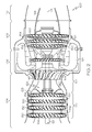
- FIG. 3 illustrated is a more detailed view of portions of the compressor section 104, the combustion section 106, and the turbine section 108. More specifically, illustrated in greater detail is the secondary cooling airflow system 123.
- FIG. 3 again only half the structure is shown, it being substantially rotationally symmetric about the centerline and axis of rotation 101. Illustrated is a portion of the high pressure impeller 144, including an impellor blade 145 and an impeller hub 147.
- stators 132 FIG. 2
- a final stationary vane, or diffuser vane 133 acts as a diffuser for deswirling and diffusing the pressurized airflow just prior to its entry to the high pressure compressor 122.
- An opening 136 downstream of diffuser vane 133 allows diffused, pressurized cooling airflow to enter a collecting chamber 138 in a substantially non-swirling condition.
- a vortex spoiler 180 is positioned in communication with the collecting chamber 138, and is rigidly secured to a rotary member 148 for rotation therewith. The vortex spoiler 180 provides additional cooling for downstream components, such as those found in the combustor section 106 and turbine section 108.
- a hub 156 extends axially between and couples the vortex spoiler 180 to the high pressure compressor 122.
- FIGs. 4-8 schematic representations of the vortex spoiler 180, is depicted.
- the vortex spoiler 180 differs from traditional designs in that it uses a curve rotated profile instead of a straight radially configured profile.
- illustrated in simplified orthogonal view and a side view is an embodiment of the vortex spoiler 180, including a plurality of inlet ports 182 and a plurality of outlet ports 184.
- FIG. 6 as best shown in a side sectional view taken through line 6-6 of FIG. 5 , each pairing of an inlet port 182 and an outlet port 184 defines a passageway, or duct, 186 there between.
- the vortex spoiler 180 is further defined by a radial exterior sidewall 188 and a radial interior sidewall 190.
- the radial exterior sidewall 188 and the radial interior sidewall 190 define there between a core area 191 best illustrated in FIG. 6 , through which the plurality of ducts 186 are formed.
- the plurality of ducts 186 extend axially between the radial exterior sidewall 188 and the radial interior sidewall 190, and through the core 191, to provide for the flow of a cooling airflow 192.
- the plurality of ducts 186 are configured such that the radial inner end of each of the plurality of ducts 186, proximate each of the plurality of outlet ports 184, is as large as possible. More particularly, the entirety of the plurality of ducts 186 are maintained at as substantially as large a cross section as reasonably possible to avoid a velocity increase and subsequent pressure drop of the cooling airflow 192 in the plurality of ducts 186.
- the vortex spoiler 180 incorporates a curved rotated profile. More specifically, as best illustrated in FIG. 6 , each of the plurality of ducts 186 are formed having a curved rotated profile in relation to their inlet port 182 and their outlet port 184.
- the vortex spoiler 180 is machined using an end mill process.
- a collet of a drill is positioned 90 degrees normal to a billet surface.
- the initial drilling process would create a bore having an interior diameter at each inlet port 182 formed at a preselected angle in a range of 65-75 degrees normal to the surface of the radial exterior sidewall 188, and preferably at a preselected angle of 70 degrees normal to the surface of the radial exterior sidewall 188, instead of the typical 90 degrees.
- the curved rotated profile is formed by rotating the lower inner diameter section of the bore 191, and more specifically forming the bore 191 having an interior diameter at each outlet port 184 formed at a preselected angle in a range of 15-25 degrees normal to the surface of the radial interior sidewall 190, and preferably at a preselected angle of 20 degrees normal to the surface of the radial interior sidewall 190 as best illustrated in FIG. 6 .
- This allows for each of the plurality of ducts 186 to have an entrance angle at each of the plurality of inlet ports 182 of approximately 70 degrees relative to the surface of the radial exterior sidewall and an exit angle at each of the plurality of outlet ports 184 of approximately 20 degrees relative to the surface of radial interior sidewall 190.
- the curved rotated profile of the plurality of ducts 186 provides reduced pressure loss and up to approximately 25% more mass flow to downstream turbine components.
- the percentage of preservation of static pressure varies proportionately with total mass flow of the secondary air flow, i.e., a larger total mass flow would result in a proportionately larger preservation of static pressure.
- the vortex spoiler 180 having a curved rotated profile provides for a reduction in the static pressure drop by approximately 20% and in turn provides more pressure (about 2-3.5 pounds more pressure) towards an exit of a duct 149 ( FIG. 3 ) that leads directly to turbine section 108 ( FIG. 3 ).
- tangential stresses are also reduced with the vortex spoiler 180 yielding approximately 17% less stress concentration at the plurality of inlet ports 182 of the vortex spoiler 180.
- the vortex spoiler described herein thus provides an improved secondary cooling means for turbine engine components.
- the vortex spoiler utilizes a curved radially profile, defined by a plurality of bores offset at an angle approximately 70 degrees normal to the surface at an inlet port, and having an outlet port radially curved at an angle of approximately 20 degrees offset from the inlet port.
- the new design of the vortex spoiler improves the overall cooling delivery means by decreasing static pressure loss and tangential stresses.
Landscapes
- Engineering & Computer Science (AREA)
- Mechanical Engineering (AREA)
- General Engineering & Computer Science (AREA)
- Chemical & Material Sciences (AREA)
- Combustion & Propulsion (AREA)
- Turbine Rotor Nozzle Sealing (AREA)
Applications Claiming Priority (1)
| Application Number | Priority Date | Filing Date | Title |
|---|---|---|---|
| US11/691,307 US7708519B2 (en) | 2007-03-26 | 2007-03-26 | Vortex spoiler for delivery of cooling airflow in a turbine engine |
Publications (1)
| Publication Number | Publication Date |
|---|---|
| EP1978209A2 true EP1978209A2 (de) | 2008-10-08 |
Family
ID=39561799
Family Applications (1)
| Application Number | Title | Priority Date | Filing Date |
|---|---|---|---|
| EP08102899A Withdrawn EP1978209A2 (de) | 2007-03-26 | 2008-03-25 | Vortex-Spoiler zur Lieferung eines kühlenden Luftstroms in einem Turbinenmotor |
Country Status (3)
| Country | Link |
|---|---|
| US (1) | US7708519B2 (de) |
| EP (1) | EP1978209A2 (de) |
| CA (1) | CA2627112A1 (de) |
Cited By (5)
| Publication number | Priority date | Publication date | Assignee | Title |
|---|---|---|---|---|
| EP2546462A3 (de) * | 2011-07-15 | 2014-02-26 | United Technologies Corporation | Loch für ein Kühlungssystem einer drehbaren Komponente |
| CN103867235A (zh) * | 2012-12-18 | 2014-06-18 | 中航商用航空发动机有限责任公司 | 一种管式减涡器引气系统 |
| EP2864597A4 (de) * | 2012-06-20 | 2016-06-15 | United Technologies Corp | Bearbeitete aerodynamische interkompressorauslässe |
| EP3244037A1 (de) * | 2016-05-10 | 2017-11-15 | General Electric Company | Laufradmontierter wirbelspoiler |
| CN109494595A (zh) * | 2018-12-29 | 2019-03-19 | 江苏荣辉电力设备制造有限公司 | 一种室外用高效散热电气箱 |
Families Citing this family (24)
| Publication number | Priority date | Publication date | Assignee | Title |
|---|---|---|---|---|
| US8453463B2 (en) * | 2009-05-27 | 2013-06-04 | Pratt & Whitney Canada Corp. | Anti-vortex device for a gas turbine engine compressor |
| US8348599B2 (en) * | 2010-03-26 | 2013-01-08 | General Electric Company | Turbine rotor wheel |
| US8677766B2 (en) | 2010-04-12 | 2014-03-25 | Siemens Energy, Inc. | Radial pre-swirl assembly and cooling fluid metering structure for a gas turbine engine |
| US8876933B2 (en) * | 2010-12-08 | 2014-11-04 | Hamilton Sundstrand Corporation | Core diffuser for deoiler/breather |
| US20130199207A1 (en) * | 2012-02-03 | 2013-08-08 | General Electric Company | Gas turbine system |
| US9085983B2 (en) * | 2012-03-29 | 2015-07-21 | General Electric Company | Apparatus and method for purging a gas turbine rotor |
| US9091173B2 (en) * | 2012-05-31 | 2015-07-28 | United Technologies Corporation | Turbine coolant supply system |
| CA2920482A1 (en) | 2013-08-16 | 2015-02-19 | General Electric Company | Flow vortex spoiler |
| KR101509382B1 (ko) * | 2014-01-15 | 2015-04-07 | 두산중공업 주식회사 | 댐핑 클램프를 구비한 가스 터빈 |
| US10543442B2 (en) * | 2015-03-30 | 2020-01-28 | Cummins Filtration Ip, Inc. | Multiple stage rotating coalescer devices |
| CN107614083B (zh) | 2015-06-09 | 2020-05-08 | 康明斯过滤Ip公司 | 通过动态密封保持旋转聚结器正向再循环的系统和方法 |
| US10537842B2 (en) | 2015-06-09 | 2020-01-21 | Cummins Filtration Ip, Inc. | Systems and methods for utilizing a low-friction rotating coalescer contact seal |
| US10974182B2 (en) | 2015-08-21 | 2021-04-13 | Cummins Filtration Ip, Inc. | High speed rotating crankcase ventilation filter media and media pack |
| WO2017040256A1 (en) | 2015-08-28 | 2017-03-09 | Cummins Filtration Ip, Inc | Rotating coalescing element with directed liquid drainage and gas outlet |
| PL415045A1 (pl) | 2015-12-03 | 2017-06-05 | General Electric Company | Tarcze turbiny i sposoby ich wytwarzania |
| US11066998B2 (en) * | 2016-03-30 | 2021-07-20 | Mitsubishi Heavy Industries, Ltd. | Compressor rotor, compressor and gas turbine |
| WO2017189516A1 (en) | 2016-04-28 | 2017-11-02 | Cummins Filtration Ip, Inc. | Inside-out rotating coalescer with gas exit through hollow shaft |
| US10247017B2 (en) | 2016-06-29 | 2019-04-02 | General Electric Company | System and method for gas bearing support of turbine |
| US9995175B2 (en) | 2016-06-29 | 2018-06-12 | General Electric Company | System and method for gas bearing support of turbine |
| EP3504440A4 (de) * | 2016-08-25 | 2020-04-01 | Danfoss A/S | Kühlkompressor |
| US10934943B2 (en) | 2017-04-27 | 2021-03-02 | General Electric Company | Compressor apparatus with bleed slot and supplemental flange |
| US11105212B2 (en) * | 2019-01-29 | 2021-08-31 | Honeywell International Inc. | Gas turbine engines including tangential on-board injectors and methods for manufacturing the same |
| US11220922B1 (en) * | 2020-06-17 | 2022-01-11 | Honeywell International Inc. | Monolithic diffuser and deswirl flow structure for gas turbine engine |
| CN114810664B (zh) * | 2022-04-26 | 2023-05-02 | 北京航空航天大学 | 一种用于压气机的变管径减涡器及其减涡系统 |
Family Cites Families (19)
| Publication number | Priority date | Publication date | Assignee | Title |
|---|---|---|---|---|
| DE2633291C3 (de) * | 1976-07-23 | 1981-05-14 | Kraftwerk Union AG, 4330 Mülheim | Gasturbinenanlage mit Kühlung durch zwei unabhängige Kühlluftströme |
| US4236869A (en) * | 1977-12-27 | 1980-12-02 | United Technologies Corporation | Gas turbine engine having bleed apparatus with dynamic pressure recovery |
| US4541774A (en) * | 1980-05-01 | 1985-09-17 | General Electric Company | Turbine cooling air deswirler |
| US4439104A (en) * | 1981-06-15 | 1984-03-27 | The Garrett Corporation | Compressor inlet guide vane and vortex-disturbing member assembly |
| US4531356A (en) * | 1981-06-15 | 1985-07-30 | The Garrett Corporation | Intake vortex whistle silencing apparatus and methods |
| FR2552164B1 (fr) * | 1983-09-21 | 1986-12-26 | Snecma | Disque de compresseur avec accelerateur centripete integre pour l'aspiration d'air dans un dispositif de refroidissement d'une turbine a gaz |
| GB2207465B (en) * | 1987-07-18 | 1992-02-19 | Rolls Royce Plc | A compressor and air bleed arrangement |
| US4844695A (en) * | 1988-07-05 | 1989-07-04 | Pratt & Whitney Canada Inc. | Variable flow radial compressor inlet flow fences |
| US5373691A (en) * | 1993-06-23 | 1994-12-20 | Allied-Signal Inc. | Inlet guide vane dewhistler |
| US5851105A (en) * | 1995-06-28 | 1998-12-22 | General Electric Company | Tapered strut frame |
| US5997244A (en) * | 1997-05-16 | 1999-12-07 | Alliedsignal Inc. | Cooling airflow vortex spoiler |
| US6398487B1 (en) * | 2000-07-14 | 2002-06-04 | General Electric Company | Methods and apparatus for supplying cooling airflow in turbine engines |
| DK174261B1 (da) * | 2000-09-29 | 2002-10-21 | Bonus Energy As | Anordning til brug ved regulering af luftstrømning omkring en vindmøllevinge |
| US6626640B2 (en) * | 2001-11-19 | 2003-09-30 | Durmitor Inc. | Fan with reduced noise |
| US6872048B2 (en) * | 2001-11-26 | 2005-03-29 | Lennox Industries, Inc. | Fan with reduced noise generation |
| DE10159670A1 (de) * | 2001-12-05 | 2003-06-18 | Rolls Royce Deutschland | Wirbelgleichrichter im Hochdruckverdichter einer Gasturbine |
| US6773225B2 (en) * | 2002-05-30 | 2004-08-10 | Mitsubishi Heavy Industries, Ltd. | Gas turbine and method of bleeding gas therefrom |
| DE10310815A1 (de) * | 2003-03-12 | 2004-09-23 | Rolls-Royce Deutschland Ltd & Co Kg | Wirbelgleichrichter in Röhrenbauweise mit Haltering |
| FR2889565B1 (fr) * | 2005-08-03 | 2012-05-18 | Snecma | Compresseur a prelevement d'air centripete |
-
2007
- 2007-03-26 US US11/691,307 patent/US7708519B2/en not_active Expired - Fee Related
-
2008
- 2008-03-25 EP EP08102899A patent/EP1978209A2/de not_active Withdrawn
- 2008-03-26 CA CA002627112A patent/CA2627112A1/en not_active Abandoned
Cited By (8)
| Publication number | Priority date | Publication date | Assignee | Title |
|---|---|---|---|---|
| EP2546462A3 (de) * | 2011-07-15 | 2014-02-26 | United Technologies Corporation | Loch für ein Kühlungssystem einer drehbaren Komponente |
| EP2864597A4 (de) * | 2012-06-20 | 2016-06-15 | United Technologies Corp | Bearbeitete aerodynamische interkompressorauslässe |
| US9638201B2 (en) | 2012-06-20 | 2017-05-02 | United Technologies Corporation | Machined aerodynamic intercompressor bleed ports |
| CN103867235A (zh) * | 2012-12-18 | 2014-06-18 | 中航商用航空发动机有限责任公司 | 一种管式减涡器引气系统 |
| CN103867235B (zh) * | 2012-12-18 | 2015-12-23 | 中航商用航空发动机有限责任公司 | 一种管式减涡器引气系统 |
| EP3244037A1 (de) * | 2016-05-10 | 2017-11-15 | General Electric Company | Laufradmontierter wirbelspoiler |
| CN109494595A (zh) * | 2018-12-29 | 2019-03-19 | 江苏荣辉电力设备制造有限公司 | 一种室外用高效散热电气箱 |
| CN109494595B (zh) * | 2018-12-29 | 2020-05-22 | 江苏荣辉电力设备制造有限公司 | 一种室外用散热电气箱 |
Also Published As
| Publication number | Publication date |
|---|---|
| US7708519B2 (en) | 2010-05-04 |
| CA2627112A1 (en) | 2008-09-26 |
| US20090067986A1 (en) | 2009-03-12 |
Similar Documents
| Publication | Publication Date | Title |
|---|---|---|
| US7708519B2 (en) | Vortex spoiler for delivery of cooling airflow in a turbine engine | |
| EP1365154B1 (de) | Gegenrotationsboosterverdichter für Gasturbinentriebwerk | |
| CN101178029B (zh) | 级间冷却式涡轮发动机 | |
| JP5802380B2 (ja) | 多段の先端ファン | |
| US6647730B2 (en) | Turbine engine having turbine cooled with diverted compressor intermediate pressure air | |
| EP2520763B1 (de) | Laufrad | |
| CN108868900A (zh) | 具有翼型件和插入件的涡轮发动机 | |
| EP1421257B1 (de) | Doppelstrom - verdichter | |
| CA2577461A1 (en) | Leaned deswirl vanes behind a centrifugal compressor in a gas turbine engine | |
| US20100111688A1 (en) | Axial-centrifugal compressor with ported shroud | |
| EP3293382B1 (de) | Gasturbinentriebwerkverdichterlaufradkühlluftsenken | |
| EP3061975B1 (de) | Axialverdichter mit fluidrückführung | |
| GB2536628A (en) | HPT Integrated interstage seal and cooling air passageways | |
| CA2567940C (en) | Methods and apparatuses for gas turbine engines | |
| US9909494B2 (en) | Tip turbine engine with aspirated compressor | |
| CN116696858A (zh) | 具有平衡腔的涡轮发动机 | |
| US11732592B2 (en) | Method of cooling a turbine blade | |
| CN113833571B (zh) | 具有成组的偏转器的涡轮发动机构件 | |
| US11739643B2 (en) | Method and apparatus for cooling a portion of a counter-rotating turbine engine | |
| EP4290053A1 (de) | Passives kühlsystem zur schaufelspitzenabstandsoptimierung | |
| CN118499084A (zh) | 低压涡轮 |
Legal Events
| Date | Code | Title | Description |
|---|---|---|---|
| PUAI | Public reference made under article 153(3) epc to a published international application that has entered the european phase |
Free format text: ORIGINAL CODE: 0009012 |
|
| 17P | Request for examination filed |
Effective date: 20080325 |
|
| AK | Designated contracting states |
Kind code of ref document: A2 Designated state(s): AT BE BG CH CY CZ DE DK EE ES FI FR GB GR HR HU IE IS IT LI LT LU LV MC MT NL NO PL PT RO SE SI SK TR |
|
| AX | Request for extension of the european patent |
Extension state: AL BA MK RS |
|
| STAA | Information on the status of an ep patent application or granted ep patent |
Free format text: STATUS: THE APPLICATION HAS BEEN WITHDRAWN |
|
| 18W | Application withdrawn |
Effective date: 20091002 |