EP1978194B1 - Device for holding open a side door of a vehicle - Google Patents
Device for holding open a side door of a vehicle Download PDFInfo
- Publication number
- EP1978194B1 EP1978194B1 EP20080154118 EP08154118A EP1978194B1 EP 1978194 B1 EP1978194 B1 EP 1978194B1 EP 20080154118 EP20080154118 EP 20080154118 EP 08154118 A EP08154118 A EP 08154118A EP 1978194 B1 EP1978194 B1 EP 1978194B1
- Authority
- EP
- European Patent Office
- Prior art keywords
- door
- cable
- vehicle
- doorpost
- retaining
- Prior art date
- Legal status (The legal status is an assumption and is not a legal conclusion. Google has not performed a legal analysis and makes no representation as to the accuracy of the status listed.)
- Not-in-force
Links
Images




Classifications
-
- E—FIXED CONSTRUCTIONS
- E05—LOCKS; KEYS; WINDOW OR DOOR FITTINGS; SAFES
- E05C—BOLTS OR FASTENING DEVICES FOR WINGS, SPECIALLY FOR DOORS OR WINDOWS
- E05C17/00—Devices for holding wings open; Devices for limiting opening of wings or for holding wings open by a movable member extending between frame and wing; Braking devices, stops or buffers, combined therewith
- E05C17/02—Devices for holding wings open; Devices for limiting opening of wings or for holding wings open by a movable member extending between frame and wing; Braking devices, stops or buffers, combined therewith by mechanical means
- E05C17/04—Devices for holding wings open; Devices for limiting opening of wings or for holding wings open by a movable member extending between frame and wing; Braking devices, stops or buffers, combined therewith by mechanical means with a movable bar or equivalent member extending between frame and wing
- E05C17/36—Devices for holding wings open; Devices for limiting opening of wings or for holding wings open by a movable member extending between frame and wing; Braking devices, stops or buffers, combined therewith by mechanical means with a movable bar or equivalent member extending between frame and wing comprising a flexible member, e.g. chains
-
- E—FIXED CONSTRUCTIONS
- E05—LOCKS; KEYS; WINDOW OR DOOR FITTINGS; SAFES
- E05C—BOLTS OR FASTENING DEVICES FOR WINGS, SPECIALLY FOR DOORS OR WINDOWS
- E05C17/00—Devices for holding wings open; Devices for limiting opening of wings or for holding wings open by a movable member extending between frame and wing; Braking devices, stops or buffers, combined therewith
- E05C17/02—Devices for holding wings open; Devices for limiting opening of wings or for holding wings open by a movable member extending between frame and wing; Braking devices, stops or buffers, combined therewith by mechanical means
- E05C17/04—Devices for holding wings open; Devices for limiting opening of wings or for holding wings open by a movable member extending between frame and wing; Braking devices, stops or buffers, combined therewith by mechanical means with a movable bar or equivalent member extending between frame and wing
- E05C17/12—Devices for holding wings open; Devices for limiting opening of wings or for holding wings open by a movable member extending between frame and wing; Braking devices, stops or buffers, combined therewith by mechanical means with a movable bar or equivalent member extending between frame and wing consisting of a single rod
- E05C17/20—Devices for holding wings open; Devices for limiting opening of wings or for holding wings open by a movable member extending between frame and wing; Braking devices, stops or buffers, combined therewith by mechanical means with a movable bar or equivalent member extending between frame and wing consisting of a single rod sliding through a guide
- E05C17/203—Devices for holding wings open; Devices for limiting opening of wings or for holding wings open by a movable member extending between frame and wing; Braking devices, stops or buffers, combined therewith by mechanical means with a movable bar or equivalent member extending between frame and wing consisting of a single rod sliding through a guide concealed, e.g. for vehicles
- E05C17/206—Devices for holding wings open; Devices for limiting opening of wings or for holding wings open by a movable member extending between frame and wing; Braking devices, stops or buffers, combined therewith by mechanical means with a movable bar or equivalent member extending between frame and wing consisting of a single rod sliding through a guide concealed, e.g. for vehicles with elastomeric springs to hold wing open
Definitions
- This invention relates to a device for holding open a side door of a vehicle.
- DE 90 11 713 U discloses a hydraulic operated device to hold open a door of a vehicle comprising a rigid rod intermediate section that slides between two hydraulic operated retaining elements.
- DE9011713U also suggests to provide a pressure-rigid cable instead of the above mentioned rigid rod.
- the aim of this invention is to create a device to hold open a side door of a vehicle, which provides an easy and inexpensive solution to the above-mentioned problems.
- a device is provided to hold open a side door of a vehicle, as defined in claim 1.
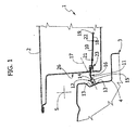
- FIG 1 shows a device for holding open a side door 2 of a vehicle 3 (partially illustrated).
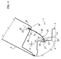
- the door 2 is hinged in a way not shown to a doorpost 4 of the vehicle 3 so as to rotate about an axis 5 that is substantially vertical between a closed position ( Figure 1 ) and a completely open position ( Figure 4 ).
- the device 1 is capable of holding the door 2 in two positions ( Figures 2 and 3 ), which are intermediate between the completely open and closed positions.
- the device 1 comprises an elongated element which, according to the invention, comprises a flexible cable 10 made up of strands (in particular steel strands) and has one end 11 fixed to the doorpost 4.
- the fixing is achieved by means of a terminal element 12, which comprises two perforated lugs 13 connected by means of screws (not shown) to a face 14 of the doorpost 4; and an intermediate tubular portion 15 secured to the end 11.
- the cable 10 is connected to the doorpost 4 without any hinge or joint, since the shape of the cable 10 automatically adapts itself, by elastic flexion, to the position of the door 2 about the axis 5, forming a loop 16.
- the axis 17 of the portion 15 is perpendicular to the face 14: the cable 10 assumes a substantially straight path along the axis 17 when the door is in a reference position which is intermediate between the completely open and closed positions.
- the loop 16 has a concavity which faces towards the passenger compartment when the door 2 is closed ( Figure 1 ) and faces outwards when the door 2 is completely open ( Figure 4 ). Thanks to its own elasticity, the cable 10 tends naturally to return to a straight configuration, and so exerts an elastic action to rotate the door 2 towards the said reference position. This elasticity could be used to facilitate the opening and/or closing of the door 2, arranging the above-mentioned reference position at an appropriate angle in relation to the closed position.
- this reference position corresponds to half of the total angle of rotation and coincides substantially with the intermediate open position shown in Figure 2 .
- the cable 10 has a free end 18, which is opposite the end 11 and bears a stop head 19, secured to the end 18 and defining the end of travel for the completely open position of the door 2.
- the cable 10 has a cylindrical section, which is constant except for two intermediate portions 21 and 22. Portions 21, 22 have respective protuberances of a substantially spherical shape, are spaced apart longitudinally along the cable 10 and are defined, in particular, by an additional amount of material.
- Portions 21, 22 co-operate with a retaining device 23 to hold the door 2 in the two intermediate open positions shown in Figures 2 and 3 .
- the device 23 comprises a connecting body 24, which is made of prestressed steel and comprises two perforated lugs 25 fixed by means of screws (not shown) to a face 26 of the door 2 oriented towards the face 14.
- the body 24 has an intermediate box-portion, which extends inside the door 2 along an axis 29 perpendicular to the face 26.
- the portion 28 comprises two walls 30, which are parallel and spaced apart and have respective pairs of slots 32 which make the walls 30 elastically yielding in a direction 33 perpendicular to the walls 30 and the axis 29.
- the walls 30 have respective plugs 35, which are connected to the walls 30 in fixed positions, for example by push- or bayonet-fitting.
- the plugs 35 have respective recesses, which are symmetrical to each other in relation to a supporting surface of the plugs 35 and define a passage 36 along the axis 29.
- This passage 36 is engaged in a sliding manner by the cable 10 and comprises a retaining seat 37 that is substantially complementary to the shape of the portions 21, 22.
- the plugs 35 are preferably made of an elastically yielding material and axially hold the cable 10 when the portions 21, 22 engage in the seat 37.
- the portions 21, 22 come out of the seat 37 when the door 2 is subjected to an opening or closing torque that exceeds a pre-set threshold.
- the plugs 35 and the walls 30 are designed so as to exert a retaining load along the axis 29 which corresponds to a pre-set closing torque threshold on the door 2 of approximately 40 Nm.
- the door 2 When the portion 21 engages in the seat 37, the door 2 is in the intermediate open position nearest the closed position ( Figure 2 ): the axes 17 and 29 substantially coincide, so the cable 10 behaves substantially like a rigid rod that slides axially in the seat 37.
- a closing torque on the door 2 in this position causes a compression along the axis 29 on the cable 10: the number and diameter of the strands and the diameter of the cable 10 are designed so that the cable 10 remains substantially rigid when a closing torque is applied so as to overcome the retaining force exerted by the device 23.
- the number and diameter of the strands, the diameter of the cable 10, the distance between the portion 22 and the end 11, and the retaining force exerted by the device 23 along the axis 29 are designed as explained, on the one hand, to limit the flexion and thus the curvature of the cable 10 when the door 2 is closed from a position close to this intermediate open position, so as to enable the portion 22 enter/leave the seat 37 when the above-mentioned pre-set threshold is exceeded; and on the other hand, to allow the cable 10 to flex sufficiently when the door 2 is opened completely, so as to avoid the use of a hinge or a joint at the element 12.
- a cable 10 can be chosen having a diameter of 6 millimetres, with seven strands and seven wires for each strand, and with protuberances of the portions 21, 22 having a diameter of approximately 9-10 millimetres.
- the distance between the end 11 and the portion 22 could be approximately 140 mm.
- the door 2 opens completely until the head 19 enters into the portion 28 and abuts axially against the plugs 35: the head 19 is shaped so that it cannot enter the passage 36, so as to define the opening limit of the door 2.
- a guide is provided to guide the end 18 on exiting the portion 28 inside the door 2 during the closing movement of the door 2: the characteristics and positioning of this guide are determined depending on the space available inside the door 2 (for example depending on whether any reinforcing ribs and/or runners for the windows of the door 2 are present).
- the protuberances of the portions 21, 22 and the plugs 35 do away with the presence of moving bodies, such as retaining rollers and pre-loaded springs, and reduce the production and assembly times and costs of the device 23.
- moving bodies such as retaining rollers and pre-loaded springs
- the holding of the door 2 in the intermediate opening positions could be achieved by using elements other than the plugs 35 shown by way of example and/or by using retaining seats of shapes other than the spherical seat 37.
- the stranded cable 10 could possibly have a covering; in this case the holding of the door 2 in the intermediate opening positions could be achieved by protuberances or recesses made directly in such covering.
- the end 11 could be fixed to the door 2 and the device 23 could be mounted on the doorpost 4 (in this case, however, draining any water that entered from the doorpost 4 through the device 23 could be somewhat complicated).
Landscapes
- Engineering & Computer Science (AREA)
- Mechanical Engineering (AREA)
- Hinge Accessories (AREA)
- Closing And Opening Devices For Wings, And Checks For Wings (AREA)
- Window Of Vehicle (AREA)
Description
- This invention relates to a device for holding open a side door of a vehicle.
- There are known solutions for holding open a door of a motor vehicle that comprise a rigid rod which is hinged at one end to the doorpost and has an intermediate section that slides between two rollers mounted on the door. The rollers are pushed by respective calibrated springs against opposite edges of the rod, one of which has one or more recesses. These recesses, when engaged by the corresponding roller, define the position of the door in respective intermediate opening positions.
- In order to move the door from these positions, an opening or closing torque must be exerted so as to overcome the pre-loading of the springs and thus disengage the roller from the recess.
- The document
DE 90 11 713 U discloses a hydraulic operated device to hold open a door of a vehicle comprising a rigid rod intermediate section that slides between two hydraulic operated retaining elements.DE9011713U also suggests to provide a pressure-rigid cable instead of the above mentioned rigid rod. - These known solutions are far from satisfactory since they require a relatively large number of components, particularly as regards the means of connection to the doorpost and to the door. Furthermore, the above-described known solutions are relatively cumbersome and expensive and impose undesired restrictions on the design of the door's other components (for example as regards the position and vertical sliding of the door's side window), due to the presence of the rollers, the rigid rod and the springs.
- The aim of this invention is to create a device to hold open a side door of a vehicle, which provides an easy and inexpensive solution to the above-mentioned problems. According to this invention, a device is provided to hold open a side door of a vehicle, as defined in
claim 1. - The invention shall now be described with reference to the accompanying drawings, which show a non-limiting embodiment thereof, in which:
-
Figure 1 is a schematic plan view of a preferred embodiment of the device for holding open a side door of a vehicle according to this invention, while said door is in a closed position; -
Figures 2 to 4 are similar toFigure 1 and show the door in two intermediate open positions and in one completely open position respectively; -
Figure 5 is a side view of a component of the device shown inFigures 1-4 ; -
Figure 6 is a section along Line VI-VI ofFigure 5 . - In
Figure 1, 1 shows a device for holding open aside door 2 of a vehicle 3 (partially illustrated). - The
door 2 is hinged in a way not shown to adoorpost 4 of thevehicle 3 so as to rotate about anaxis 5 that is substantially vertical between a closed position (Figure 1 ) and a completely open position (Figure 4 ). Thedevice 1 is capable of holding thedoor 2 in two positions (Figures 2 and3 ), which are intermediate between the completely open and closed positions. - With reference to
Figures 1 to 4 , thedevice 1 comprises an elongated element which, according to the invention, comprises aflexible cable 10 made up of strands (in particular steel strands) and has oneend 11 fixed to thedoorpost 4. The fixing is achieved by means of aterminal element 12, which comprises twoperforated lugs 13 connected by means of screws (not shown) to aface 14 of thedoorpost 4; and an intermediatetubular portion 15 secured to theend 11. In other words, thecable 10 is connected to thedoorpost 4 without any hinge or joint, since the shape of thecable 10 automatically adapts itself, by elastic flexion, to the position of thedoor 2 about theaxis 5, forming aloop 16. - The
axis 17 of theportion 15 is perpendicular to the face 14: thecable 10 assumes a substantially straight path along theaxis 17 when the door is in a reference position which is intermediate between the completely open and closed positions. Thus theloop 16 has a concavity which faces towards the passenger compartment when thedoor 2 is closed (Figure 1 ) and faces outwards when thedoor 2 is completely open (Figure 4 ). Thanks to its own elasticity, thecable 10 tends naturally to return to a straight configuration, and so exerts an elastic action to rotate thedoor 2 towards the said reference position. This elasticity could be used to facilitate the opening and/or closing of thedoor 2, arranging the above-mentioned reference position at an appropriate angle in relation to the closed position. - In particular, this reference position corresponds to half of the total angle of rotation and coincides substantially with the intermediate open position shown in
Figure 2 . - Also according to the accompanying Figures, the
cable 10 has afree end 18, which is opposite theend 11 and bears astop head 19, secured to theend 18 and defining the end of travel for the completely open position of thedoor 2. - The
cable 10 has a cylindrical section, which is constant except for twointermediate portions Portions cable 10 and are defined, in particular, by an additional amount of material. -
Portions retaining device 23 to hold thedoor 2 in the two intermediate open positions shown inFigures 2 and3 . Thedevice 23 comprises a connectingbody 24, which is made of prestressed steel and comprises twoperforated lugs 25 fixed by means of screws (not shown) to aface 26 of thedoor 2 oriented towards theface 14. Thebody 24 has an intermediate box-portion, which extends inside thedoor 2 along anaxis 29 perpendicular to theface 26. - With reference to
Figures 5 and6 , theportion 28 comprises twowalls 30, which are parallel and spaced apart and have respective pairs ofslots 32 which make thewalls 30 elastically yielding in adirection 33 perpendicular to thewalls 30 and theaxis 29. Inside theportion 28, thewalls 30 haverespective plugs 35, which are connected to thewalls 30 in fixed positions, for example by push- or bayonet-fitting. Theplugs 35 have respective recesses, which are symmetrical to each other in relation to a supporting surface of theplugs 35 and define apassage 36 along theaxis 29. Thispassage 36 is engaged in a sliding manner by thecable 10 and comprises a retainingseat 37 that is substantially complementary to the shape of theportions plugs 35 are preferably made of an elastically yielding material and axially hold thecable 10 when theportions seat 37. Theportions seat 37 when thedoor 2 is subjected to an opening or closing torque that exceeds a pre-set threshold. For example, theplugs 35 and thewalls 30 are designed so as to exert a retaining load along theaxis 29 which corresponds to a pre-set closing torque threshold on thedoor 2 of approximately 40 Nm. - When the
portion 21 engages in theseat 37, thedoor 2 is in the intermediate open position nearest the closed position (Figure 2 ): theaxes cable 10 behaves substantially like a rigid rod that slides axially in theseat 37. In fact, a closing torque on thedoor 2 in this position causes a compression along theaxis 29 on the cable 10: the number and diameter of the strands and the diameter of thecable 10 are designed so that thecable 10 remains substantially rigid when a closing torque is applied so as to overcome the retaining force exerted by thedevice 23. - When the
portion 22 engages in theseat 37, however, thedoor 2 is in the intermediate open position closest to the completely open position (Figure 3 ). Closing thedoor 2 causes a compression along theaxis 29 which tends further to flex thecable 10 and, therefore, to accentuate the concavity of theloop 16, as schematically illustrated by the dotted lines inFigure 3 (the same consideration also applies when closing from the completely open position in order to make theportion 22 engage in the seat 37). The number and diameter of the strands, the diameter of thecable 10, the distance between theportion 22 and theend 11, and the retaining force exerted by thedevice 23 along theaxis 29 are designed as explained, on the one hand, to limit the flexion and thus the curvature of thecable 10 when thedoor 2 is closed from a position close to this intermediate open position, so as to enable theportion 22 enter/leave theseat 37 when the above-mentioned pre-set threshold is exceeded; and on the other hand, to allow thecable 10 to flex sufficiently when thedoor 2 is opened completely, so as to avoid the use of a hinge or a joint at theelement 12. - By way of example, for a retaining force corresponding to a pre-set closing torque threshold of approximately 40 Nm, a
cable 10 can be chosen having a diameter of 6 millimetres, with seven strands and seven wires for each strand, and with protuberances of theportions end 11 and theportion 22 could be approximately 140 mm. - The
door 2 opens completely until thehead 19 enters into theportion 28 and abuts axially against the plugs 35: thehead 19 is shaped so that it cannot enter thepassage 36, so as to define the opening limit of thedoor 2. - According to a variation not shown, a guide is provided to guide the
end 18 on exiting theportion 28 inside thedoor 2 during the closing movement of the door 2: the characteristics and positioning of this guide are determined depending on the space available inside the door 2 (for example depending on whether any reinforcing ribs and/or runners for the windows of thedoor 2 are present). - From the above, it seems clear that the use of flexible stranded cables fixed to the
doorpost 4 enables the known solutions having rigid rods or levers to be simplified as it allows the hinges that connect these rods or levers to the doorpost to be eliminated. Furthermore, the strands that make up thewire 10 are flexible so theend 18 does not constitute a rigid restriction inside thedoor 2 when thedoor 2 is closed. In particular, it is possible to guide theend 18 so as to make it bend and slide into a position which does not interfere with the other internal components of thedoor 2. In other words, this solution gives greater freedom in the design of the internal components of thedoor 2. - Furthermore, the protuberances of the
portions plugs 35 do away with the presence of moving bodies, such as retaining rollers and pre-loaded springs, and reduce the production and assembly times and costs of thedevice 23. By reducing the number of components, the weight of thedevice 1 in comparison to known solutions can also be reduced and it is therefore easier to handle during fitting onto the vehicle. - It is also possible to eliminate the traditional and expensive seals that protect the
door 2 from dust and replace them with a suitable and simple sponge element positioned at the entrance ofportion 28 and passed through by thecable 10. - Lastly, from the above it is clear that the
device 1 described can be modified and varied without departing from the scope of protection of the invention, as defined in the attached claims. - In particular, the holding of the
door 2 in the intermediate opening positions could be achieved by using elements other than theplugs 35 shown by way of example and/or by using retaining seats of shapes other than thespherical seat 37. - The stranded
cable 10 could possibly have a covering; in this case the holding of thedoor 2 in the intermediate opening positions could be achieved by protuberances or recesses made directly in such covering. - Lastly, in a manner paralleling that described above, the
end 11 could be fixed to thedoor 2 and thedevice 23 could be mounted on the doorpost 4 (in this case, however, draining any water that entered from thedoorpost 4 through thedevice 23 could be somewhat complicated).
Claims (11)
- Device (1) to hold open a side door (2) of a vehicle (3), such device comprising:- an elongated element;- connection means (12) to connect one end (11) of said elongated element either to the door (2) or a doorpost (4) of said vehicle (3);- retaining means (23) that can be fixed to the other of either said door (2) or said doorpost (4), passed through by said elongated element, and co-operating with a contoured portion (21,22) of said elongated element in order to hold open said door (2) in a releasable manner in an intermediate open position;
said elongated element comprising a cable (10) extending through said retaining means (23);
wherein:- said cable (10) is a stranded flexible cable (10), and- said connection means are fixing means (12). - Device according to claim 1, characterised in that said contoured portion (21, 22) comprises a protuberance in a fixed relative position along said flexible stranded cable (10), and in that said retaining means (23) comprise a retaining seat (37) to house said protuberance in a releasable manner.
- Device according to claim 2, characterised in that it comprises two plugs (35) arranged opposite each other and having respective recesses, which define a passage (36) engaged in a sliding manner by said flexible stranded cable (10) and comprising said retaining seat (37).
- Device according to claim 3, characterised in that said plugs (35) are mounted on respective walls (30) made elastically yielding by means of respective openings (32).
- Device according to claim 3 or 4, characterised in that said plugs (35) are made of an elastically yielding material.
- Device according to any of claims 2 to 5, characterised in that said retaining seat (37) is a spherical seat.
- Device according to any of claims 2 to 6, characterised in that said flexible stranded cable (10) has two protuberances spaced apart to define respective intermediate open positions.
- Device according to any of the preceding claims, characterised in that it comprises a guide to guide a sliding free end (18) of said flexible stranded cable (10) on exiting said retaining means (23).
- Vehicle (3) comprising:- a doorpost (4);- a side door (2) hinged to said doorpost (4) to rotate about a substantially vertical axis (5) between a completely open position and a completely closed position;- a device (1) made according to any of the preceding claims.
- Vehicle according to claim 9, characterised in that said flexible stranded cable (10) assumes a straight path when said door (2) is in an intermediate position between said completely open and closed positions.
- Vehicle according to claim 10, characterised in that said flexible stranded cable (10) assumes a straight path when said door (2) is in a central position between said completely open and closed positions.
Applications Claiming Priority (1)
| Application Number | Priority Date | Filing Date | Title |
|---|---|---|---|
| ITTO20070244 ITTO20070244A1 (en) | 2007-04-05 | 2007-04-05 | DEVICE TO KEEP A SIDE DOOR OF A VEHICLE OPEN |
Publications (2)
| Publication Number | Publication Date |
|---|---|
| EP1978194A1 EP1978194A1 (en) | 2008-10-08 |
| EP1978194B1 true EP1978194B1 (en) | 2011-08-24 |
Family
ID=38291242
Family Applications (1)
| Application Number | Title | Priority Date | Filing Date |
|---|---|---|---|
| EP20080154118 Not-in-force EP1978194B1 (en) | 2007-04-05 | 2008-04-04 | Device for holding open a side door of a vehicle |
Country Status (3)
| Country | Link |
|---|---|
| EP (1) | EP1978194B1 (en) |
| ES (1) | ES2368871T3 (en) |
| IT (1) | ITTO20070244A1 (en) |
Family Cites Families (7)
| Publication number | Priority date | Publication date | Assignee | Title |
|---|---|---|---|---|
| US1483912A (en) * | 1924-02-19 | Jooorcheck | ||
| US1657528A (en) * | 1926-09-28 | 1928-01-31 | Concealed Door Check Company | Doorcheck strap |
| US3174787A (en) * | 1962-10-22 | 1965-03-23 | Irvin R Kolman | Adjustable tension straps |
| DE2456191A1 (en) * | 1974-11-28 | 1976-08-12 | Stanley Werke Gmbh | Opening limiter device for doors and windows - has captive blade spring with striker ends housed in door and frame sections behind guide slit plates |
| DE2655155A1 (en) * | 1976-12-06 | 1978-07-20 | Scharwaechter Gmbh Co Kg | Vehicle door retaining rod - has body formed with thickened section which slides between resiliently mounted plastics components acting as holding brake |
| DE9011713U1 (en) | 1990-08-11 | 1991-12-05 | Ed. Scharwächter GmbH & Co. KG, 5630 Remscheid | Power assisted car door lock |
| CA2501197A1 (en) * | 2005-03-18 | 2006-05-30 | Cristiaan Stefanus Lambertus Petrus Van Den Heuvel | Door retaining rod for a doorstop |
-
2007
- 2007-04-05 IT ITTO20070244 patent/ITTO20070244A1/en unknown
-
2008
- 2008-04-04 ES ES08154118T patent/ES2368871T3/en active Active
- 2008-04-04 EP EP20080154118 patent/EP1978194B1/en not_active Not-in-force
Also Published As
| Publication number | Publication date |
|---|---|
| ES2368871T3 (en) | 2011-11-23 |
| ITTO20070244A1 (en) | 2008-10-06 |
| EP1978194A1 (en) | 2008-10-08 |
Similar Documents
| Publication | Publication Date | Title |
|---|---|---|
| KR101457738B1 (en) | Electric power supply device for slide door | |
| CN102267359B (en) | Door edge protection device | |
| EP2210752A1 (en) | Device for opening and closing vehicle door | |
| KR101555173B1 (en) | Vehicle seat, in particular automobile seat | |
| CN101512091A (en) | Integrated hinge assembly with spring biased prop arm | |
| JP2003025850A (en) | Slide door feeding structure | |
| BRPI1102669A2 (en) | vehicle | |
| CA2639778A1 (en) | Open roof construction | |
| US20090079222A1 (en) | Cover means for a displaceably mounted vehicle window pane | |
| EP1331341B1 (en) | Tailgate stabilizer | |
| US20050044794A1 (en) | Guide assembly for sliding doors or pivotable sliding doors of vehicles and sliding door or pivotable sliding door | |
| DE102019134088B4 (en) | Hinge mechanism | |
| CN102079234B (en) | Sliding roof sunshade assembly | |
| US20060168892A1 (en) | Motor vehicle door | |
| GB2307290A (en) | Balancing strut | |
| CN107995897B (en) | Screening device for a motor vehicle window | |
| EP1978194A1 (en) | Device for holding open a side door of a vehicle | |
| CN109641510B (en) | Shading device for a glass pane of a motor vehicle | |
| JP2002309851A (en) | Drive unit for automotive sliding door | |
| CN115349209A (en) | Cable guide and motor vehicle | |
| EP2665613B1 (en) | Movement device for a motor vehicle interior trim part, and interior trim part | |
| DE102010032459A1 (en) | Flap arrangement for luggage compartment of e.g. motor car, has detent designed as retainer into which detent region is pivoted when reaching maximum open position of flap, where retainer retains detent region at three sides | |
| CN219953061U (en) | Window regulator | |
| EP2050617B1 (en) | Backrest of a vehicle seat | |
| KR101207763B1 (en) | Door closer |
Legal Events
| Date | Code | Title | Description |
|---|---|---|---|
| PUAI | Public reference made under article 153(3) epc to a published international application that has entered the european phase |
Free format text: ORIGINAL CODE: 0009012 |
|
| AK | Designated contracting states |
Kind code of ref document: A1 Designated state(s): AT BE BG CH CY CZ DE DK EE ES FI FR GB GR HR HU IE IS IT LI LT LU LV MC MT NL NO PL PT RO SE SI SK TR |
|
| AX | Request for extension of the european patent |
Extension state: AL BA MK RS |
|
| 17P | Request for examination filed |
Effective date: 20090407 |
|
| AKX | Designation fees paid |
Designated state(s): DE ES FR IT |
|
| 17Q | First examination report despatched |
Effective date: 20090622 |
|
| GRAP | Despatch of communication of intention to grant a patent |
Free format text: ORIGINAL CODE: EPIDOSNIGR1 |
|
| GRAC | Information related to communication of intention to grant a patent modified |
Free format text: ORIGINAL CODE: EPIDOSCIGR1 |
|
| GRAS | Grant fee paid |
Free format text: ORIGINAL CODE: EPIDOSNIGR3 |
|
| GRAA | (expected) grant |
Free format text: ORIGINAL CODE: 0009210 |
|
| AK | Designated contracting states |
Kind code of ref document: B1 Designated state(s): DE ES FR IT |
|
| REG | Reference to a national code |
Ref country code: DE Ref legal event code: R096 Ref document number: 602008009052 Country of ref document: DE Effective date: 20111020 |
|
| REG | Reference to a national code |
Ref country code: ES Ref legal event code: FG2A Ref document number: 2368871 Country of ref document: ES Kind code of ref document: T3 Effective date: 20111123 |
|
| PLBE | No opposition filed within time limit |
Free format text: ORIGINAL CODE: 0009261 |
|
| STAA | Information on the status of an ep patent application or granted ep patent |
Free format text: STATUS: NO OPPOSITION FILED WITHIN TIME LIMIT |
|
| 26N | No opposition filed |
Effective date: 20120525 |
|
| REG | Reference to a national code |
Ref country code: DE Ref legal event code: R097 Ref document number: 602008009052 Country of ref document: DE Effective date: 20120525 |
|
| REG | Reference to a national code |
Ref country code: FR Ref legal event code: ST Effective date: 20121228 |
|
| PG25 | Lapsed in a contracting state [announced via postgrant information from national office to epo] |
Ref country code: IT Free format text: LAPSE BECAUSE OF NON-PAYMENT OF DUE FEES Effective date: 20120404 Ref country code: FR Free format text: LAPSE BECAUSE OF NON-PAYMENT OF DUE FEES Effective date: 20120430 |
|
| REG | Reference to a national code |
Ref country code: DE Ref legal event code: R119 Ref document number: 602008009052 Country of ref document: DE Effective date: 20121101 |
|
| REG | Reference to a national code |
Ref country code: ES Ref legal event code: FD2A Effective date: 20130715 |
|
| PG25 | Lapsed in a contracting state [announced via postgrant information from national office to epo] |
Ref country code: ES Free format text: LAPSE BECAUSE OF NON-PAYMENT OF DUE FEES Effective date: 20120405 |
|
| PG25 | Lapsed in a contracting state [announced via postgrant information from national office to epo] |
Ref country code: DE Free format text: LAPSE BECAUSE OF FAILURE TO SUBMIT A TRANSLATION OF THE DESCRIPTION OR TO PAY THE FEE WITHIN THE PRESCRIBED TIME-LIMIT Effective date: 20121101 |