EP1977956A2 - Installation structure and method of vehicular suspension - Google Patents
Installation structure and method of vehicular suspension Download PDFInfo
- Publication number
- EP1977956A2 EP1977956A2 EP08004706A EP08004706A EP1977956A2 EP 1977956 A2 EP1977956 A2 EP 1977956A2 EP 08004706 A EP08004706 A EP 08004706A EP 08004706 A EP08004706 A EP 08004706A EP 1977956 A2 EP1977956 A2 EP 1977956A2
- Authority
- EP
- European Patent Office
- Prior art keywords
- suspension
- side members
- vehicle body
- breakable
- end portion
- Prior art date
- Legal status (The legal status is an assumption and is not a legal conclusion. Google has not performed a legal analysis and makes no representation as to the accuracy of the status listed.)
- Granted
Links
- 239000000725 suspension Substances 0.000 title claims abstract description 172
- 238000009434 installation Methods 0.000 title claims abstract description 34
- 238000000034 method Methods 0.000 title claims abstract description 6
- 230000000149 penetrating effect Effects 0.000 claims description 28
- 230000008878 coupling Effects 0.000 claims description 7
- 238000010168 coupling process Methods 0.000 claims description 7
- 238000005859 coupling reaction Methods 0.000 claims description 7
- 230000002787 reinforcement Effects 0.000 claims description 6
- 230000005540 biological transmission Effects 0.000 claims description 5
- 230000000694 effects Effects 0.000 description 2
- 238000003754 machining Methods 0.000 description 2
- 238000012986 modification Methods 0.000 description 2
- 230000004048 modification Effects 0.000 description 2
- 101150004367 Il4i1 gene Proteins 0.000 description 1
Images


Classifications
-
- B—PERFORMING OPERATIONS; TRANSPORTING
- B62—LAND VEHICLES FOR TRAVELLING OTHERWISE THAN ON RAILS
- B62D—MOTOR VEHICLES; TRAILERS
- B62D21/00—Understructures, i.e. chassis frame on which a vehicle body may be mounted
- B62D21/15—Understructures, i.e. chassis frame on which a vehicle body may be mounted having impact absorbing means, e.g. a frame designed to permanently or temporarily change shape or dimension upon impact with another body
- B62D21/152—Front or rear frames
- B62D21/155—Sub-frames or underguards
Definitions
- the present invention relates to installation structure and method of a vehicular suspension located at a forward portion of an automotive vehicle.
- a Japanese Patent Application Publication No. 2002-2528 published on January 9, 2002 exemplifies a previously proposed installation structure of a vehicular suspension located at a forward (or front) portion of an automotive vehicle.
- front side members are disposed at left and right side portions of a vehicle body along a vehicular forward-and-rearward (longitudinal) direction.
- a forward (front) end portion of each of the front side members is linked to a front bumper reinforcement.
- a rearward (rear) end portion of each of the front side members is bent toward a lower side of the vehicle body and is linked to left and right side sills.
- a suspension member is disposed on a lower side of the (left and right) front side members to be intersected to the left and right front side members, left and right forward end portions of the suspension member are linked to the respective front side members via suspension links, and a rearward end portion of the suspension member is linked to the respective front side members.
- An engine and a transmission both thereof constituting a drive unit, are disposed in an engine compartment enclosed with the left and right front side members, the front bumper reinforcement, and the suspension member and left and right front road wheels are connected to a drive shaft extended along a left-and-right (lateral or vehicular width) direction of the vehicle body.
- suspension links are tightened with bolts to the respective front side members and notches are provided on bolt penetrating holes at tightening portions of the respective suspension links.
- a (an excessively high) load is applied from the forward portion of the vehicle body, engine compartment forward-and-rearward portions of the respective front side members are buckled.
- the drive unit is moved (retracted) toward a rearward portion of the vehicle body and the drive shaft is interfered with the respective suspension links.
- the tightening of the suspension links to the front side members is released due to presence of the notches of the tightening (coupling) portions of the suspension links.
- an object of the present invention to provide installation structure and method of a vehicular suspension which have no deformation and rupture (or break) when the load input during the assembly operation of the suspension and during the actual running of the vehicle occurs and have suspension links, each suspension link having a breakable portion at which the break (or rupture) of the suspension links assuredly occurs without failure against the (excessively high) load input from the forward portion of the vehicle body.
- an installation structure of a vehicular suspension comprising: first and second side members, each of the first and second side members being disposed on a corresponding side portion of a vehicle body along a forward-and-rearward direction of the vehicle body; a drive unit mounted on a space between the first and second side members; a drive shaft extended from the drive unit in a width direction of the vehicle body and connected to drive wheels; a suspension member formed on the space between the first and second side members and disposed at a lower-and-rearward portion of the drive unit; and first and second suspension links, each of the first and second suspension links linking a corresponding one of the first and second side members with the suspension member and being provided with a breakable portion which breaks due to a load generated when the load applied to a forward end portion of at least one of the first and second side members causes the drive unit and the drive shaft to be moved toward a rearward direction of the vehicle body to bring the drive shaft in contact against a corresponding one of the first and second suspension
- an installation method of a vehicular suspension comprising: disposing each of first and second side members on a corresponding side portion of a vehicle body along a forward-and-rearward direction of the vehicle body; mounting a drive unit on a space between the first and second side members; extending a drive shaft from the drive unit in a width direction of the vehicle body and connecting the drive shaft to drive wheels; forming a suspension member on the space between the first and second side members and disposing the suspension member at a lower-and-rearward portion of the drive unit; and linking via each of first and second suspension links a corresponding one of the first and second side members with the suspension member and providing a breakable portion on a corresponding one of the first and second suspension links, the breakable portion breaking due to a load generated when the load applied to a forward end portion of at least one of the first and second side members causes the drive unit and the drive shaft to be moved toward a rearward direction of the vehicle body to bring the drive shaft in contact against a
- the suspension links are assuredly broken at the respective breakable portions without failure against the (excessively high) load input from the forward portion of the vehicle body so that a deformation (quantity) of the vehicle body due to a retraction of the drive unit toward the rearward portion of the vehicle body becomes small and the deformation and break (deformation and rupture) at the breakable portion due to the load input during the assembly operation of the suspension and during the actual running of the vehicle.
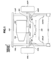
- Fig. 1 is a plan view of an installation structure of a vehicular suspension in a first preferred embodiment according to the present invention.
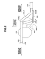
- Fig. 2 is a left side view of the installation structure of the vehicular suspension shown in Fig. 1 .
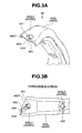
- Figs. 3A and 3B are explanatory views for explaining a breakable portion of a left suspension link shown in Figs. 1 and 2 .
- Fig. 4 is a graph representing a relationship between an installation angle ( ⁇ ) of each of the suspension links and a magnitude of a load input in the first embodiment of the installation structure of the vehicular suspension according to the present invention.
- Figs. 5A and 5B are analysis results of the load input applied to the suspension shown in Figs. 1 and 2 in cases where the breakable portions are provided on left and right suspension links in the case of the first embodiment shown in Figs. 1 and 2 or not provided on left and right suspension links.
- Figs. 6A and 6B are same plan views of the left suspension link in the case of a second preferred embodiment according to the present invention.
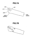
- Figs. 7A and 7B are same plan views of the left suspension link in the case of a third preferred embodiment according to the present invention.
- FIG. 1 shows a first embodiment of an installation structure of a vehicular suspension according to the present invention.
- each of left and right front side members 100L, 100R is disposed on a corresponding one of left and right side portions of a vehicle body along a forward-and-rearward (longitudinal) direction of the vehicle body and respective forward end portions of left and right front side members 100L, 100R are linked to a front bumper reinforcement 200.
- respective rearward end portions of left and right front side members 100L, 100R are bent toward a lower portion of the vehicle body so as to be linked to left and right side sills 500.
- a suspension member 300 is disposed on a lower portion of left and right front side members 100L, 100R so as to be intersected to left and right front side members 100L, 100R.
- Left and right forward end portions 300LF, 300RF of suspension member 300 are linked to left and right front side members 100L, 100R via left and right suspension links 400L, 400R, respectively.
- Rearward end portions 300LB, 300RB of suspension member 300 are linked to left and right front side members 100L, 100R, respectively. That is to say, suspension member 300 is formed on a space between left and right front side members 100L, 100R and is positioned on a lower-and-rearward position of a drive unit.
- An engine 600 and a transmission 700, both constituting the drive unit, are disposed in an engine compartment enclosed with left and right front side members 100L, 100R, front bumper reinforcement 200, and suspension member 300.
- Left and right front road wheels 900L, 900R which are drive wheels are mounted on (connected to) a drive shaft 800 extended in a leftward-and-rightward (a width) direction of the vehicle body.
- Figs. 3A and 3B show one of left and right suspension links 400L (400R).
- Each suspension link 400L (400R) as shown in Fig. 2 , has its upper end portion 400LU (400RU) tightened via a bolt penetrating hole 401 (refer to Figs.
- a bolt penetrating hole recess portion 403 continuous to bolt penetrating hole 401 is provided on a tip portion 400T of suspension link 400L (400R) at bolt penetrating hole 401 of upper end portion 400LU (400RU) of suspension link 400L (400R).
- an end recess portion 404 is provided on tip portion 400T of suspension link 400L (400R) near to bolt penetrating hole 401.
- These bolt penetrating hole 403 and end recess portion 404 are set to be aligned in a load input direction (in an arrow-marked direction as viewed from AF in Fig. 3B ) applied to suspension link 400L (400R) when the load is inputted from the forward portion of the vehicle body.
- these bolt penetrating hole recess portion 403, end recess portion 404, and a portion of suspension link 400L (400R) interposed between bolt penetrating hole recess portion 403 and end recess portion 404 constitute a breakable portion (also called, a rupturable portion) 410 which breaks (or ruptures) in a case where a (an excessively high) load input occurs.
- breakable portion 410 is positioned on upper end portion 400LU (400RU) of suspension link 400L (400R) and is provided on a tightening (coupling) portion between each of suspension links 400L (400R) and corresponding one of left and right front side members 100L (100R).
- a cross sectional area of breakable portion 410 in a direction at which the load input occurs (the arrow-marked direction of AF in Fig. 3B ) is set to be smaller than that of each of adjacent portions (in arrow-marked directions of AN1 and AN2 in Fig. 3B ) to breakable portion 410. It should be noted that the same structure of right suspension link 400R as left suspension link 400L can be taken.
- Each suspension link 400L, 400R is arranged to have a configuration in order for an elongate direction of each of left and right suspension links 400L, 400R to be intersected to a virtual line (a horizontal or lateral line denoted by a dot-and-dash line in Fig. 1 ) extended in parallel to drive shaft 800 toward a corresponding one of left and right suspension links 400L, 400R through a predetermined angle ( ⁇ ) (like an inverted Japanese character (katakana) of ) as viewed from a top portion of the vehicle body as shown in Fig. 1 .
- ⁇ like an inverted Japanese character (katakana) of
- Fig. 4 shows an analysis result of the relationship between predetermined angle ⁇ of each suspension link 400L, 400R with respect to the horizontal line of the vehicle body and the load input applied to breakable portion 410.
- a range of predetermined angle ⁇ which can break (or rupture) breakable portion 410 is from 22 degrees to 62 degrees when the (excessively high) load input equal to or higher than a predetermined load input F0 by which breakable portion 410 is positively broken (ruptured) is applied from the forward portion of the vehicle body to breakable portion 410.
- each suspension link 400L, 400R is installed in order for predetermined angle ⁇ to be set in this angular range. Consequently, the load input which can assuredly break breakable portion 410 of each of suspension links 400L, 400R can be applied to breakable portion 410.
- Left and right suspension links 400L, 400R are disposed in the way as described above and, in a case where the load input equal to or higher than the predetermined load input is applied from the forward portion of the vehicle body, the load applied to a linkage position between suspension link 400L (400R) and front side member 100L (100R) provides a tensile load since a contacting position between each of suspension links 400L, 400R and drive shaft 800 is positioned at a more rearward side than the linkage position described above so that breakable portion 410 can more assuredly break breakable portion 410.
- breakable portion 410 is placed above drive shaft 800 so that a moment applied to breakable portion 410 from a portion subjected to the load becomes large for breakable portion 410 to become easy to be broken (ruptured). Furthermore, breakable portion 410 is provided on a coupling (tightening) portion between suspension link 400L (400R) and front suspension member 100L (100R), viz., the (upper) end portion of suspension link 400L (400R). Therefore, a machining of breakable portion 410 becomes easy (breakable portion for the other (right) suspension link 400R is the same).
- Figs. 5A and 5B show analytical results of deformed states of front side member 100R and suspension member 300 when the load input described above is applied from the forward portion of the vehicle body in cases where breakable portion 410 is provided on suspension link 400R and no breakable portion is provided thereon.
- a retraction (retraction distance) of front side member 100R indicated 101 millimeters in a case where no breakable portion is provided on suspension link 400R and indicated 85 millimeters in a case where breakable portion 410 is provided on suspension link 400R. Consequently, a deformation (quantity) of front side member 100R was improved by 16 millimeters.
- breakable portion 410 has not taken a notch structure, deformation and rupture (break) of breakable portion 410 do not occur due to the load input during the assembly operation of the suspension and during the actual run of the vehicle.
- Figs. 6A and 6B show same plan views of one suspension link 400L (400R) in a second preferred embodiment of the installation structure of the suspension according to the present invention.
- Bolt penetrating hole recess portion 403 which is continued to bolt penetrating hole recess portion 401 is provided at tip portion 400T of suspension link 400L (400R) in bolt penetrating hole 401 of upper end portion 400LU of suspension link 400L. This bolt penetrating hole recess portion 403 is set to be aligned to the load input direction (arrow-marked direction of AF in Fig.
- breakable portion 411 which breaks (ruptures) in the case where the load input described above from the forward portion of the vehicle body occurs.
- This structure sets the cross sectional area in the load input direction (arrow-marked direction AF in Fig. 6B ) of breakable portion 411 to be smaller than adjacent portions (AN1 and AN2 directions in Fig. 6B ) of breakable portion 411.
- breakable portion 411 is set so that the same effects can be obtained as those described in the first embodiment.
- Figs. 7A and 7B show same plan views of same suspension link 400L (400R) in a third embodiment according to the present invention.
- the form of breakable portion 412 is different from breakable portion 410 described in the first embodiment and the other suspension elements in the third embodiment are the same as those described in the first embodiment. Hence, only the form of breakable portion 412 will herein be described.
- End recess portion 404 is provided on tip portion 400T of suspension link 400L (400R) near to bolt penetrating hole 401 of upper end portion 400LU (400RU) of suspension link 400L (400R).
- This end recess portion 404 is set to be aligned in the load input direction (arrow-marked AF direction in Fig. 7B ) applied to suspension link 400L (400R) in a case where the load input described above is applied from the forward portion of the vehicle body.
- This bolt penetrating hole 401 and the portion interposed between bolt penetrating hole 401 and end recess portion 404 constitute breakable portion 412 which breaks in a case where the load input described above occurs.
- This structure causes the cross sectional area of breakable portion 412 in the load input direction (arrow-marked AF direction in Fig. 7B ) to be set to be smaller than those of the adjacent portions (arrow-marked AN1 and AN2 portions in Fig. 7 ) to breakable portion 412. It should be noted that the same structure in the case of other (right) suspension link 400R can be taken in this embodiment. As described above, since breakable portion 412 is set, the same advantages as described in the first embodiment can be obtained.
- An installation structure of a vehicular suspension comprises first and second side members, each of the first and second side members being disposed on a corresponding side portion of a vehicle body along a forward-and-rearward direction of the vehicle body; a drive unit mounted on a space between the first and second side members; a drive shaft extended from the drive unit in a width direction of the vehicle body and connected to drive wheels; a suspension member formed on the space between the first and second side members and disposed at a lower-and-rearward portion of the drive unit; and first and second suspension links, each of the first and second suspension links linking a corresponding one of the first and second side members with the suspension member and being provided with a breakable portion which breaks due to a load generated when the load applied to a forward end portion of at least one of the first and second side members causes the drive unit and the drive shaft to be moved toward a rearward direction of the vehicle body to bring the drive shaft in contact against a corresponding one of the first and second suspension links.
- term of first corresponds to left and
- each suspension link with respect to the load input from the forward portion of the vehicle body is broken at the breakable portion thereof, together with the reduced deformation quantity of the vehicle body due to the retraction of the engine and the transmission, and deformation and rupture (break) of each suspension link due to the load input during the assembly operation thereof and during the actual traveling does not occur.
- the breakable portion is provided on the upper portion of each suspension link.
- the drive shaft is ordinarily placed at the lower portion of the vehicle and the breakable portion is placed at the upper portion of the drive shaft, the moment applied from the portion subjected to the load to the breakable portion becomes large so that the break (rupture) at each breakable portion can become easier to occur.
- a moment applied to each of breakable portions has a long moment arm and each suspension link is brought in contact with the drive shaft obliquely (as shown in Fig. 1 ) so that the break of breakable portion can more easily occur.
- the breakable portion is provided on the coupling portion of each suspension link between the suspension link and the side member. Since the breakable portion is provided on the coupling portion, the machining of the breakable portion becomes easy.
- each suspension link is arranged to have a configuration in order for an elongate direction of each suspension link to be intersected to the lateral line (the horizontal line) extended in parallel to drive shaft 800 toward the corresponding one of the suspension links through a predetermined angle ( ⁇ ) as viewed from a top portion of the vehicle body as shown in Fig1 .
- ⁇ predetermined angle
- An installation structure of a vehicular suspension comprises: first and second side members, each of the first and second side members being disposed on a corresponding side portion of a vehicle body along a forward-and-rearward direction of the vehicle body; a drive unit mounted on a space between the first and second side members; a drive shaft extended from the drive unit in a width direction of the vehicle body and connected to drive wheels; a suspension member formed on the space between the first and second side members and disposed at a lower-and-rearward portion of the drive unit; and first and second suspension links, each of the first and second suspension links linking a corresponding one of the first and second side members with the suspension member and being provided with a breakable portion which breaks due to a load generated when the load equal to or higher than predetermined load input (F0) is applied to a forward end portion of at least one (or both) of the first and second side members.
- F0 predetermined load input
- each breakable portion 410, 411, 412 is merely exemplified and the forms, magnitudes, positions, and number of bolt penetrating hole recess portion 403 and end recess portion 404 can arbitrarily be set.
- the forms of bolt penetrating hole 401 and tip portion 400T may be set for the cross sectional area of the breakable portion in the load input direction to be small as compared with those of the adjacent portions surrounding thereof.
Landscapes
- Engineering & Computer Science (AREA)
- Chemical & Material Sciences (AREA)
- Combustion & Propulsion (AREA)
- Transportation (AREA)
- Mechanical Engineering (AREA)
- Body Structure For Vehicles (AREA)
- Vehicle Body Suspensions (AREA)
Abstract
Description
- The present invention relates to installation structure and method of a vehicular suspension located at a forward portion of an automotive vehicle.
- A Japanese Patent Application Publication No.
2002-2528 published on January 9, 2002 - However, since the notches are provided on the tightening (coupling) portions of the respective suspension links in the previously proposed installation structure of the vehicular suspension located at the forward portion of the vehicle body disclosed in the above-described Japanese Patent Application Publication, there is a possibility of occurrence of deformation and rupture (or called, break) in the respective suspension links due to the load input during an assembly operation of the suspension and during an actual running of the vehicle.
- It is, hence, an object of the present invention to provide installation structure and method of a vehicular suspension which have no deformation and rupture (or break) when the load input during the assembly operation of the suspension and during the actual running of the vehicle occurs and have suspension links, each suspension link having a breakable portion at which the break (or rupture) of the suspension links assuredly occurs without failure against the (excessively high) load input from the forward portion of the vehicle body.
- According to one aspect of the present invention, there is provided an installation structure of a vehicular suspension, comprising: first and second side members, each of the first and second side members being disposed on a corresponding side portion of a vehicle body along a forward-and-rearward direction of the vehicle body; a drive unit mounted on a space between the first and second side members; a drive shaft extended from the drive unit in a width direction of the vehicle body and connected to drive wheels; a suspension member formed on the space between the first and second side members and disposed at a lower-and-rearward portion of the drive unit; and first and second suspension links, each of the first and second suspension links linking a corresponding one of the first and second side members with the suspension member and being provided with a breakable portion which breaks due to a load generated when the load applied to a forward end portion of at least one of the first and second side members causes the drive unit and the drive shaft to be moved toward a rearward direction of the vehicle body to bring the drive shaft in contact against a corresponding one of the first and second suspension links.
- According to another aspect of the present invention, there is provided an installation method of a vehicular suspension, comprising: disposing each of first and second side members on a corresponding side portion of a vehicle body along a forward-and-rearward direction of the vehicle body; mounting a drive unit on a space between the first and second side members; extending a drive shaft from the drive unit in a width direction of the vehicle body and connecting the drive shaft to drive wheels; forming a suspension member on the space between the first and second side members and disposing the suspension member at a lower-and-rearward portion of the drive unit; and linking via each of first and second suspension links a corresponding one of the first and second side members with the suspension member and providing a breakable portion on a corresponding one of the first and second suspension links, the breakable portion breaking due to a load generated when the load applied to a forward end portion of at least one of the first and second side members causes the drive unit and the drive shaft to be moved toward a rearward direction of the vehicle body to bring the drive shaft in contact against a corresponding one of the first and second suspension links.
- In the present invention, since the suspension links are assuredly broken at the respective breakable portions without failure against the (excessively high) load input from the forward portion of the vehicle body so that a deformation (quantity) of the vehicle body due to a retraction of the drive unit toward the rearward portion of the vehicle body becomes small and the deformation and break (deformation and rupture) at the breakable portion due to the load input during the assembly operation of the suspension and during the actual running of the vehicle. The other objects and features of this invention will become understood from the following description with reference to the accompanying drawings.
-
Fig. 1 is a plan view of an installation structure of a vehicular suspension in a first preferred embodiment according to the present invention. -
Fig. 2 is a left side view of the installation structure of the vehicular suspension shown inFig. 1 . -
Figs. 3A and 3B are explanatory views for explaining a breakable portion of a left suspension link shown inFigs. 1 and2 . -
Fig. 4 is a graph representing a relationship between an installation angle (θ) of each of the suspension links and a magnitude of a load input in the first embodiment of the installation structure of the vehicular suspension according to the present invention. -
Figs. 5A and 5B are analysis results of the load input applied to the suspension shown inFigs. 1 and2 in cases where the breakable portions are provided on left and right suspension links in the case of the first embodiment shown inFigs. 1 and2 or not provided on left and right suspension links. -
Figs. 6A and 6B are same plan views of the left suspension link in the case of a second preferred embodiment according to the present invention. -
Figs. 7A and 7B are same plan views of the left suspension link in the case of a third preferred embodiment according to the present invention. - Reference will hereinafter be made to the drawings in order to facilitate a better understanding of the present invention.
-
Fig. 1 shows a first embodiment of an installation structure of a vehicular suspension according to the present invention. InFig. 1 , each of left and rightfront side members front side members front bumper reinforcement 200.
On the other hand, respective rearward end portions of left and rightfront side members right side sills 500. Asuspension member 300 is disposed on a lower portion of left and rightfront side members front side members suspension member 300 are linked to left and rightfront side members right suspension links suspension member 300 are linked to left and rightfront side members suspension member 300 is formed on a space between left and rightfront side members - An
engine 600 and atransmission 700, both constituting the drive unit, are disposed in an engine compartment enclosed with left and rightfront side members front bumper reinforcement 200, andsuspension member 300. Left and rightfront road wheels drive shaft 800 extended in a leftward-and-rightward (a width) direction of the vehicle body.Figs. 3A and 3B show one of left andright suspension links 400L (400R). Each suspension link 400L (400R), as shown inFig. 2 , has its upper end portion 400LU (400RU) tightened via a bolt penetrating hole 401 (refer toFigs. 3A and 3B ) onto a lower portion of each offront side members 100L (100R) with a bolt (not shown) and has its lower end portion 400LD (400RD) tightened via another bolt penetrating hole 402 (refer toFig. 3B ) onto an upper portion of forward end portion 300LF (300RF) ofsuspension member 300 with a bolt (not shown). A bolt penetrating hole recessportion 403 continuous to bolt penetratinghole 401 is provided on atip portion 400T ofsuspension link 400L (400R) atbolt penetrating hole 401 of upper end portion 400LU (400RU) ofsuspension link 400L (400R). In addition, anend recess portion 404 is provided ontip portion 400T ofsuspension link 400L (400R) near tobolt penetrating hole 401. Thesebolt penetrating hole 403 andend recess portion 404 are set to be aligned in a load input direction (in an arrow-marked direction as viewed from AF inFig. 3B ) applied tosuspension link 400L (400R) when the load is inputted from the forward portion of the vehicle body. - In this embodiment, these bolt penetrating hole recess
portion 403,end recess portion 404, and a portion ofsuspension link 400L (400R) interposed between bolt penetrating hole recessportion 403 andend recess portion 404 constitute a breakable portion (also called, a rupturable portion) 410 which breaks (or ruptures) in a case where a (an excessively high) load input occurs. As described above with reference toFigs. 3A and 3B ,breakable portion 410 is positioned on upper end portion 400LU (400RU) ofsuspension link 400L (400R) and is provided on a tightening (coupling) portion between each ofsuspension links 400L (400R) and corresponding one of left and rightfront side members 100L (100R). According to the structure described above, a cross sectional area ofbreakable portion 410 in a direction at which the load input occurs (the arrow-marked direction of AF inFig. 3B ) is set to be smaller than that of each of adjacent portions (in arrow-marked directions of AN1 and AN2 inFig. 3B ) tobreakable portion 410. It should be noted that the same structure ofright suspension link 400R asleft suspension link 400L can be taken. - Each
suspension link right suspension links Fig. 1 ) extended in parallel to driveshaft 800 toward a corresponding one of left andright suspension links ) as viewed from a top portion of the vehicle body as shown in
Fig. 1 . -
Fig. 4 shows an analysis result of the relationship between predetermined angle θ of eachsuspension link breakable portion 410. As appreciated fromFig. 4 , a range of predetermined angle θ which can break (or rupture)breakable portion 410 is from 22 degrees to 62 degrees when the (excessively high) load input equal to or higher than a predetermined load input F0 by whichbreakable portion 410 is positively broken (ruptured) is applied from the forward portion of the vehicle body tobreakable portion 410. Hence, eachsuspension link breakable portion 410 of each of suspension links 400L, 400R can be applied tobreakable portion 410. - Left and right suspension links 400L, 400R are disposed in the way as described above and, in a case where the load input equal to or higher than the predetermined load input is applied from the forward portion of the vehicle body, the load applied to a linkage position between
suspension link 400L (400R) andfront side member 100L (100R) provides a tensile load since a contacting position between each of suspension links 400L, 400R and driveshaft 800 is positioned at a more rearward side than the linkage position described above so thatbreakable portion 410 can more assuredly breakbreakable portion 410. - In addition, since
breakable portion 410 is placed abovedrive shaft 800 so that a moment applied tobreakable portion 410 from a portion subjected to the load becomes large forbreakable portion 410 to become easy to be broken (ruptured). Furthermore,breakable portion 410 is provided on a coupling (tightening) portion betweensuspension link 400L (400R) andfront suspension member 100L (100R), viz., the (upper) end portion ofsuspension link 400L (400R). Therefore, a machining ofbreakable portion 410 becomes easy (breakable portion for the other (right)suspension link 400R is the same). -
Figs. 5A and 5B show analytical results of deformed states offront side member 100R andsuspension member 300 when the load input described above is applied from the forward portion of the vehicle body in cases wherebreakable portion 410 is provided onsuspension link 400R and no breakable portion is provided thereon. As shown inFigs. 5A and 5B , when the same load input is applied from the forward portion of the vehicle body, a retraction (retraction distance) offront side member 100R indicated 101 millimeters in a case where no breakable portion is provided onsuspension link 400R and indicated 85 millimeters in a case wherebreakable portion 410 is provided onsuspension link 400R. Consequently, a deformation (quantity) offront side member 100R was improved by 16 millimeters. On the other hand, sincebreakable portion 410 has not taken a notch structure, deformation and rupture (break) ofbreakable portion 410 do not occur due to the load input during the assembly operation of the suspension and during the actual run of the vehicle. -
Figs. 6A and 6B show same plan views of onesuspension link 400L (400R) in a second preferred embodiment of the installation structure of the suspension according to the present invention. - In this embodiment, since only a form of
breakable portion 411 is different frombreakable portion 410 of the first embodiment, the structures of the other elements of the vehicular suspension are the same as those described in the first embodiment, the detailed description thereof will herein be omitted and only the form ofbreakable portion 411 will be described below. Bolt penetratinghole recess portion 403 which is continued to bolt penetratinghole recess portion 401 is provided attip portion 400T ofsuspension link 400L (400R) inbolt penetrating hole 401 of upper end portion 400LU ofsuspension link 400L. This bolt penetratinghole recess portion 403 is set to be aligned to the load input direction (arrow-marked direction of AF inFig. 6B ) when the load input is applied from the forward portion of the vehicle body. A portion oftip portion 400T ofsuspension link 400L (400R) interposed between bolt penetratinghole recess portion 403 andtip portion 400T ofsuspension link 400L constitutesbreakable portion 411 which breaks (ruptures) in the case where the load input described above from the forward portion of the vehicle body occurs. This structure sets the cross sectional area in the load input direction (arrow-marked direction AF inFig. 6B ) ofbreakable portion 411 to be smaller than adjacent portions (AN1 and AN2 directions inFig. 6B ) ofbreakable portion 411. it should be noted that the same structure of other (right)suspension link 400R can be taken. As described hereinabove,breakable portion 411 is set so that the same effects can be obtained as those described in the first embodiment. -
Figs. 7A and 7B show same plan views ofsame suspension link 400L (400R) in a third embodiment according to the present invention. In this embodiment, only the form ofbreakable portion 412 is different frombreakable portion 410 described in the first embodiment and the other suspension elements in the third embodiment are the same as those described in the first embodiment. Hence, only the form ofbreakable portion 412 will herein be described. -
End recess portion 404 is provided ontip portion 400T ofsuspension link 400L (400R) near to bolt penetratinghole 401 of upper end portion 400LU (400RU) ofsuspension link 400L (400R). Thisend recess portion 404 is set to be aligned in the load input direction (arrow-marked AF direction inFig. 7B ) applied to suspension link 400L (400R) in a case where the load input described above is applied from the forward portion of the vehicle body. Thisbolt penetrating hole 401 and the portion interposed betweenbolt penetrating hole 401 andend recess portion 404 constitutebreakable portion 412 which breaks in a case where the load input described above occurs. This structure causes the cross sectional area ofbreakable portion 412 in the load input direction (arrow-marked AF direction inFig. 7B ) to be set to be smaller than those of the adjacent portions (arrow-marked AN1 and AN2 portions inFig. 7 ) tobreakable portion 412. It should be noted that the same structure in the case of other (right)suspension link 400R can be taken in this embodiment. As described above, sincebreakable portion 412 is set, the same advantages as described in the first embodiment can be obtained. - According to the installation structure of the suspension in each of the first, second, and third embodiments according to the present invention, the following action and advantages (effects) can be obtained.
- An installation structure of a vehicular suspension comprises first and second side members, each of the first and second side members being disposed on a corresponding side portion of a vehicle body along a forward-and-rearward direction of the vehicle body; a drive unit mounted on a space between the first and second side members; a drive shaft extended from the drive unit in a width direction of the vehicle body and connected to drive wheels; a suspension member formed on the space between the first and second side members and disposed at a lower-and-rearward portion of the drive unit; and first and second suspension links, each of the first and second suspension links linking a corresponding one of the first and second side members with the suspension member and being provided with a breakable portion which breaks due to a load generated when the load applied to a forward end portion of at least one of the first and second side members causes the drive unit and the drive shaft to be moved toward a rearward direction of the vehicle body to bring the drive shaft in contact against a corresponding one of the first and second suspension links. It should be noted that term of first corresponds to left and term of second corresponds to right.
- According to the installation structure of the suspension described above, it can be assured that each suspension link with respect to the load input from the forward portion of the vehicle body is broken at the breakable portion thereof, together with the reduced deformation quantity of the vehicle body due to the retraction of the engine and the transmission, and deformation and rupture (break) of each suspension link due to the load input during the assembly operation thereof and during the actual traveling does not occur.
- In addition, since the installation structure of the suspension in each of the first, second, and third embodiments according to the present invention, the breakable portion is provided on the upper portion of each suspension link. According to the installation structure described above, since the drive shaft is ordinarily placed at the lower portion of the vehicle and the breakable portion is placed at the upper portion of the drive shaft, the moment applied from the portion subjected to the load to the breakable portion becomes large so that the break (rupture) at each breakable portion can become easier to occur. A moment applied to each of breakable portions has a long moment arm and each suspension link is brought in contact with the drive shaft obliquely (as shown in
Fig. 1 ) so that the break of breakable portion can more easily occur. - In addition, according to the installation structure of the suspension in each of the embodiments, the breakable portion is provided on the coupling portion of each suspension link between the suspension link and the side member. Since the breakable portion is provided on the coupling portion, the machining of the breakable portion becomes easy.
- In the installation structure of the suspension according to the present invention, each suspension link is arranged to have a configuration in order for an elongate direction of each suspension link to be intersected to the lateral line (the horizontal line) extended in parallel to drive
shaft 800 toward the corresponding one of the suspension links through a predetermined angle (θ) as viewed from a top portion of the vehicle body as shown inFig1 . According to the installation structure of the suspension described above, since the contact position of each suspension link with the drive shaft is placed at more rearward portion than the linkage position between each suspension link and the corresponding one of the left and right front side members, the load applied to the linkage position provides the tensile load so that the break (rupture) at the breakable portion can more be assured. An installation structure of a vehicular suspension comprises: first and second side members, each of the first and second side members being disposed on a corresponding side portion of a vehicle body along a forward-and-rearward direction of the vehicle body; a drive unit mounted on a space between the first and second side members; a drive shaft extended from the drive unit in a width direction of the vehicle body and connected to drive wheels; a suspension member formed on the space between the first and second side members and disposed at a lower-and-rearward portion of the drive unit; and first and second suspension links, each of the first and second suspension links linking a corresponding one of the first and second side members with the suspension member and being provided with a breakable portion which breaks due to a load generated when the load equal to or higher than predetermined load input (F0) is applied to a forward end portion of at least one (or both) of the first and second side members. - It should be noted that the above-described embodiment are described in order to facilitate a better understanding of the present invention and do not limit the scope of the present invention. Hence, each essential element disclosed in the above-described embodiments includes all design modifications and equivalents belonging to the scope of the present invention. For example, the form of each
breakable portion hole recess portion 403 andend recess portion 404 can arbitrarily be set. In addition, since the cross sectional area ofbreakable portion bolt penetrating hole 401 andtip portion 400T may be set for the cross sectional area of the breakable portion in the load input direction to be small as compared with those of the adjacent portions surrounding thereof. - This application is based on prior Japanese Patent Applications No.
2007-097229 2007-324186 2007-097229 2007-324186
Claims (10)
- An installation structure of a vehicular suspension, comprising:first and second side members (100L, 100R), each of the first and second side members being disposed on a corresponding side portion of a vehicle body along a forward-and-rearward direction of the vehicle body;a drive unit (600,700) mounted on a space between the first and second side members;a drive shaft (800) extended from the drive unit in a width direction of the vehicle body and connected to drive wheels;a suspension member (300) formed on the space between the first and second side members and disposed at a lower-and-rearward portion of the drive unit; andfirst and second suspension links (400L, 400R), each of the first and second suspension links linking a corresponding one of the first and second side members with the suspension member and being provided with a breakable portion (410, 411, 412) which breaks due to a load generated when the load applied to a forward end portion of at least one of the first and second side members causes the drive unit and the drive shaft to be moved toward a rearward direction of the vehicle body to bring the drive shaft in contact against a corresponding one of the first and second suspension links.
- The installation structure of the vehicular suspension as claimed in claim 1, wherein the breakable portion is provided on an upper portion of each of the first and second suspension links.
- The installation structure of the vehicular suspension as claimed in either claim 1 or 2, wherein the breakable portion is provided on a coupling portion between each of the first and second suspension links and the corresponding one of the first and second side members.
- The installation structure of the vehicular suspension as claimed in any one of the preceding claims 1 through 3, wherein each of the first and second suspension links is arranged to have a configuration in order for an elongate direction of each of the first and second suspension links to be intersected to a horizontal line extended in parallel to the drive shaft toward the corresponding one of the first and second suspension links through a predetermined angle (θ) as viewed from a top portion of the vehicle body.
- The installation structure of the vehicular suspension as claimed in claim 4, wherein the predetermined angle is set to fall in an angular range from 22 degrees to 62 degrees.
- The installation structure of the vehicular suspension as claimed in any one of the preceding claims 1 through 5, wherein the drive unit comprises an engine (600) and a transmission (700), the vehicular suspension further comprises a front bumper reinforcement (200) extended from each forward end portion of the first and second side members in the width direction of the vehicle body, the drive wheels are left and right front road wheels, and the first and second side members are left and right front side members, the engine and the transmission being disposed within an engine compartment enclosed with the front bumper reinforcement, the left and right front side members, and the suspension member.
- The installation structure of the vehicular suspension as claimed in any one of the preceding claims 1 through 6, wherein the breakable portion is constituted by a penetrating hole recess portion (403) of each of the first and second suspension links continuous to a bolt penetrating hole (401) provided on an upper end portion (400LU, 400RU) of each of the first and second suspension links through which the upper end portion thereof is tightened to a lower portion of each of the left and right front side members; an end recess portion (404) provided on a tip portion (400T) of the upper end portion of each of the first and second suspension links; and a portion of the upper end portion of each of the first and second suspension links interposed between the penetrating hole recess portion and the end recess portion, a cross sectional area of the breakable portion in a direction of the load applied from the forward end portion of at least one of the left and right front side members being set to be smaller than that of each of adjacent portions to the breakable portion.
- The installation structure of the vehicular suspension as claimed in any one of the preceding claims 1 through 6, wherein the breakable portion is constituted by a penetrating hole recess portion (403) of each of the first and second suspension links continuous to a bolt penetrating hole (401) provided on an upper end portion (400LU, 400RU) of each of the first and second suspension links through which the upper end portion thereof is tightened to a lower portion of each of the front left and right side members; a tip portion (400T) of the upper end portion of each of the first and second suspension links; and a portion of the upper end portion of each of the first and second suspension links interposed between the penetrating hole recess portion and the tip portion, a cross sectional area of the breakable portion in a direction of the load applied from the forward end portion of at least one of the left and right front side members being set to be smaller than that of each of adjacent portions to the breakable portion.
- The installation structure of the vehicular suspension as claimed in any one of the preceding claims 1 through 6, wherein the breakable portion is constituted by a bolt penetrating hole (401) provided on an upper end portion (400LU, 400RU) of each of the first and second suspension links through which the upper end portion thereof is tightened to a lower portion of each of the front left and right side members; an end recess portion (404)provided on a tip portion (400T) of the upper end portion of each of the first and second suspension links; and a portion of the upper end portion of each of the first and second suspension links interposed between the bolt penetrating hole and the end recess portion, a cross sectional area of the breakable portion in a direction of the load applied from the forward end portion of at least one of the first and second left and right front side members being set to be smaller than that of each of adjacent portions to the breakable portion.
- An installation method of a vehicular suspension, comprising:disposing each of first and second side members(100L, 100R) on a corresponding side portion of a vehicle body along a forward-and-rearward direction of the vehicle body;mounting a drive unit (600,700) on a space between the first and second side members;extending a drive shaft (800) from the drive unit in a width direction of the vehicle body and connecting the drive shaft to drive wheels;forming a suspension member (300) on the space between the first and second side members and disposing the suspension member at a lower-and-rearward portion of the drive unit; andlinking via each of first and second suspension links(400L, 400R) a corresponding one of the first and second side members with the suspension member and providing a breakable portion (410, 411, 412) on a corresponding one of the first and second suspension links, the breakable portion breaking due to a load generated when the load applied to a forward end portion of at least one of the first and second side members causes the drive unit and the drive shaft to be moved toward a rearward direction of the vehicle body to bring the drive shaft in contact against a corresponding one of the first and second suspension links.
Applications Claiming Priority (2)
| Application Number | Priority Date | Filing Date | Title |
|---|---|---|---|
| JP2007097229 | 2007-04-03 | ||
| JP2007324186A JP4956794B2 (en) | 2007-04-03 | 2007-12-17 | Suspension mounting structure |
Publications (3)
| Publication Number | Publication Date |
|---|---|
| EP1977956A2 true EP1977956A2 (en) | 2008-10-08 |
| EP1977956A3 EP1977956A3 (en) | 2011-08-24 |
| EP1977956B1 EP1977956B1 (en) | 2012-08-29 |
Family
ID=39495101
Family Applications (1)
| Application Number | Title | Priority Date | Filing Date |
|---|---|---|---|
| EP08004706A Ceased EP1977956B1 (en) | 2007-04-03 | 2008-03-13 | Installation structure and method of vehicular suspension |
Country Status (2)
| Country | Link |
|---|---|
| US (1) | US7562886B2 (en) |
| EP (1) | EP1977956B1 (en) |
Cited By (1)
| Publication number | Priority date | Publication date | Assignee | Title |
|---|---|---|---|---|
| CN106347465A (en) * | 2016-10-12 | 2017-01-25 | 山东国金汽车工程技术有限公司 | Mounting plate structure of aluminum alloy front suspension |
Families Citing this family (9)
| Publication number | Priority date | Publication date | Assignee | Title |
|---|---|---|---|---|
| US7886861B2 (en) * | 2007-09-06 | 2011-02-15 | Mitsubishi Jidosha Kogyo Kabushiki Kaisha | Electric vehicle |
| US8550543B2 (en) * | 2009-10-26 | 2013-10-08 | Toyota Jidosha Kabushiki Kaisha | Vehicle body structure |
| DE102010020497B4 (en) * | 2010-05-14 | 2020-08-06 | Audi Ag | Sheet metal component with a mounting bracket for an attachment |
| JP5664637B2 (en) * | 2012-12-07 | 2015-02-04 | トヨタ自動車株式会社 | Body front structure |
| SE540047C2 (en) * | 2015-03-17 | 2018-03-06 | Ningbo Geely Automobile Res & Development Co Ltd | An arrangement for attaching a control arm in a vehicle, and another method for directing a vehicle front wheel outside of a p assenger cell during an offset collision |
| US9616931B2 (en) * | 2015-09-16 | 2017-04-11 | GM Global Technology Operations LLC | Releasable cradle to body joint |
| US9676418B1 (en) * | 2016-01-15 | 2017-06-13 | Fca Us Llc | Vehicle crossmember assembly with pedestal detachment |
| US10703413B2 (en) * | 2016-08-31 | 2020-07-07 | Ford Global Technologies, Llc | Rear drive unit detachment system and method |
| CN110654462B (en) * | 2019-09-04 | 2021-10-15 | 东风柳州汽车有限公司 | Front auxiliary frame and vehicle body connecting device |
Citations (1)
| Publication number | Priority date | Publication date | Assignee | Title |
|---|---|---|---|---|
| JP2002002525A (en) | 2000-06-15 | 2002-01-09 | Yanmar Diesel Engine Co Ltd | Steering device for traveling vehicles |
Family Cites Families (15)
| Publication number | Priority date | Publication date | Assignee | Title |
|---|---|---|---|---|
| DE3912501A1 (en) * | 1989-04-17 | 1990-10-18 | Daimler Benz Ag | ARRANGEMENT OF A REAR AXLE ON THE BOTTOM OF THE BODY OF A PERSONAL VEHICLE |
| JP3381444B2 (en) * | 1995-03-03 | 2003-02-24 | 日産自動車株式会社 | Strength member structure of vehicle body |
| JP3351233B2 (en) * | 1995-12-27 | 2002-11-25 | トヨタ自動車株式会社 | Powertrain support device |
| GB2329877A (en) * | 1997-10-01 | 1999-04-07 | Rover Group | Vehicle subframe attached to a structure by non-frangible and frangible mountings |
| JP3803720B2 (en) * | 2000-06-15 | 2006-08-02 | 三菱自動車工業株式会社 | Body structure |
| JP3806286B2 (en) | 2000-06-15 | 2006-08-09 | 三菱自動車工業株式会社 | Body structure |
| JP3578087B2 (en) * | 2001-01-19 | 2004-10-20 | 日産自動車株式会社 | Automotive power unit layout |
| JP4788045B2 (en) * | 2001-02-19 | 2011-10-05 | マツダ株式会社 | Front body structure of automobile |
| JP3575439B2 (en) * | 2001-06-04 | 2004-10-13 | 日産自動車株式会社 | Automotive power unit layout |
| JP2003002247A (en) * | 2001-06-26 | 2003-01-08 | Nissan Motor Co Ltd | Body front structure |
| JP4023208B2 (en) * | 2002-05-10 | 2007-12-19 | 日産自動車株式会社 | Powertrain support device |
| JP3842204B2 (en) * | 2002-11-11 | 2006-11-08 | 本田技研工業株式会社 | Front body structure |
| US7232002B2 (en) * | 2003-07-18 | 2007-06-19 | University Of Washington | Apparatus for controlling rigidity of vehicle body |
| US7360621B2 (en) * | 2004-03-15 | 2008-04-22 | Mazda Motor Corporation | Suspension cross member of automotive vehicle |
| JP4276185B2 (en) * | 2005-01-26 | 2009-06-10 | 本田技研工業株式会社 | Body front structure |
-
2008
- 2008-03-13 EP EP08004706A patent/EP1977956B1/en not_active Ceased
- 2008-03-31 US US12/078,435 patent/US7562886B2/en not_active Expired - Fee Related
Patent Citations (1)
| Publication number | Priority date | Publication date | Assignee | Title |
|---|---|---|---|---|
| JP2002002525A (en) | 2000-06-15 | 2002-01-09 | Yanmar Diesel Engine Co Ltd | Steering device for traveling vehicles |
Cited By (1)
| Publication number | Priority date | Publication date | Assignee | Title |
|---|---|---|---|---|
| CN106347465A (en) * | 2016-10-12 | 2017-01-25 | 山东国金汽车工程技术有限公司 | Mounting plate structure of aluminum alloy front suspension |
Also Published As
| Publication number | Publication date |
|---|---|
| EP1977956A3 (en) | 2011-08-24 |
| US7562886B2 (en) | 2009-07-21 |
| US20080246242A1 (en) | 2008-10-09 |
| EP1977956B1 (en) | 2012-08-29 |
Similar Documents
| Publication | Publication Date | Title |
|---|---|---|
| EP1977956B1 (en) | Installation structure and method of vehicular suspension | |
| CN104284829B (en) | The frame structure of moped of automobile | |
| JP4897541B2 (en) | Shock absorbing steering device | |
| US9211915B2 (en) | Vehicle front structure | |
| US20140361560A1 (en) | Vehicle body front structure | |
| US9527464B2 (en) | Bumpers including a reinforcement bracket and vehicles incorporating the same | |
| EP1373025B2 (en) | Arrangement for underrun protection in vehicles | |
| US11970211B2 (en) | Deformation device for a motor vehicle, and motor vehicle comprising a deformation device | |
| CN107010121A (en) | Vehicle body front structure | |
| JP4956794B2 (en) | Suspension mounting structure | |
| CN109941071B (en) | Doors and vehicles with the same | |
| DE102013016766B4 (en) | Method for controlling improved deformation behavior in a motor vehicle front end and device | |
| US12151534B2 (en) | Link for a wheel suspension of a motor vehicle and wheel suspension for a wheel of a front axle of a motor vehicle | |
| JP2008120256A (en) | Shock absorption structure for vehicles | |
| US20170106823A1 (en) | Bumper device and motor vehicle | |
| JP7852612B2 (en) | Vehicle front structure | |
| CN116867702B (en) | Steering | |
| US11390327B2 (en) | Subframe brace apparatus and related assemblies for use with vehicles | |
| EP4714792A1 (en) | Bracket for connecting a cabin assembly to a chassis assembly of a heavy-duty vehicle and heavy-duty vehicle with such bracket | |
| CN119527424A (en) | Vehicle front subframe | |
| JP7567968B1 (en) | Automotive subframe structure | |
| WO2026028236A1 (en) | Automotive front body structure | |
| DE102005016456A1 (en) | Motor vehicle, has lower bumper stiffener with cooler- thrust block, where block is positioned in stiffener such that block is arrived into crash situation in unit for cooler to shift cooler to rear | |
| KR101063196B1 (en) | Vehicle body front structure | |
| JP2024053943A (en) | Vehicle bumper device |
Legal Events
| Date | Code | Title | Description |
|---|---|---|---|
| PUAI | Public reference made under article 153(3) epc to a published international application that has entered the european phase |
Free format text: ORIGINAL CODE: 0009012 |
|
| 17P | Request for examination filed |
Effective date: 20080313 |
|
| AK | Designated contracting states |
Kind code of ref document: A2 Designated state(s): AT BE BG CH CY CZ DE DK EE ES FI FR GB GR HR HU IE IS IT LI LT LU LV MC MT NL NO PL PT RO SE SI SK TR |
|
| AX | Request for extension of the european patent |
Extension state: AL BA MK RS |
|
| PUAL | Search report despatched |
Free format text: ORIGINAL CODE: 0009013 |
|
| AK | Designated contracting states |
Kind code of ref document: A3 Designated state(s): AT BE BG CH CY CZ DE DK EE ES FI FR GB GR HR HU IE IS IT LI LT LU LV MC MT NL NO PL PT RO SE SI SK TR |
|
| AX | Request for extension of the european patent |
Extension state: AL BA MK RS |
|
| RIC1 | Information provided on ipc code assigned before grant |
Ipc: B62D 21/15 20060101AFI20110720BHEP |
|
| GRAP | Despatch of communication of intention to grant a patent |
Free format text: ORIGINAL CODE: EPIDOSNIGR1 |
|
| AKX | Designation fees paid |
Designated state(s): DE FR GB |
|
| GRAS | Grant fee paid |
Free format text: ORIGINAL CODE: EPIDOSNIGR3 |
|
| GRAA | (expected) grant |
Free format text: ORIGINAL CODE: 0009210 |
|
| AK | Designated contracting states |
Kind code of ref document: B1 Designated state(s): DE FR GB |
|
| REG | Reference to a national code |
Ref country code: GB Ref legal event code: FG4D |
|
| REG | Reference to a national code |
Ref country code: DE Ref legal event code: R096 Ref document number: 602008018311 Country of ref document: DE Effective date: 20121025 |
|
| PLBE | No opposition filed within time limit |
Free format text: ORIGINAL CODE: 0009261 |
|
| STAA | Information on the status of an ep patent application or granted ep patent |
Free format text: STATUS: NO OPPOSITION FILED WITHIN TIME LIMIT |
|
| 26N | No opposition filed |
Effective date: 20130530 |
|
| REG | Reference to a national code |
Ref country code: DE Ref legal event code: R097 Ref document number: 602008018311 Country of ref document: DE Effective date: 20130530 |
|
| REG | Reference to a national code |
Ref country code: FR Ref legal event code: PLFP Year of fee payment: 9 |
|
| REG | Reference to a national code |
Ref country code: FR Ref legal event code: PLFP Year of fee payment: 10 |
|
| REG | Reference to a national code |
Ref country code: FR Ref legal event code: PLFP Year of fee payment: 11 |
|
| PGFP | Annual fee paid to national office [announced via postgrant information from national office to epo] |
Ref country code: DE Payment date: 20190226 Year of fee payment: 12 Ref country code: GB Payment date: 20190313 Year of fee payment: 12 |
|
| PGFP | Annual fee paid to national office [announced via postgrant information from national office to epo] |
Ref country code: FR Payment date: 20190213 Year of fee payment: 12 |
|
| REG | Reference to a national code |
Ref country code: DE Ref legal event code: R119 Ref document number: 602008018311 Country of ref document: DE |
|
| PG25 | Lapsed in a contracting state [announced via postgrant information from national office to epo] |
Ref country code: FR Free format text: LAPSE BECAUSE OF NON-PAYMENT OF DUE FEES Effective date: 20200331 Ref country code: DE Free format text: LAPSE BECAUSE OF NON-PAYMENT OF DUE FEES Effective date: 20201001 |
|
| GBPC | Gb: european patent ceased through non-payment of renewal fee |
Effective date: 20200313 |
|
| PG25 | Lapsed in a contracting state [announced via postgrant information from national office to epo] |
Ref country code: GB Free format text: LAPSE BECAUSE OF NON-PAYMENT OF DUE FEES Effective date: 20200313 |