EP1977916A1 - Suspension device and method for supporting wheels - Google Patents
Suspension device and method for supporting wheels Download PDFInfo
- Publication number
- EP1977916A1 EP1977916A1 EP08153984A EP08153984A EP1977916A1 EP 1977916 A1 EP1977916 A1 EP 1977916A1 EP 08153984 A EP08153984 A EP 08153984A EP 08153984 A EP08153984 A EP 08153984A EP 1977916 A1 EP1977916 A1 EP 1977916A1
- Authority
- EP
- European Patent Office
- Prior art keywords
- link
- vehicle
- linking
- rigidity
- elastic
- Prior art date
- Legal status (The legal status is an assumption and is not a legal conclusion. Google has not performed a legal analysis and makes no representation as to the accuracy of the status listed.)
- Granted
Links
- 239000000725 suspension Substances 0.000 title claims abstract description 63
- 238000000034 method Methods 0.000 title claims description 9
- 239000007788 liquid Substances 0.000 claims description 33
- 238000006073 displacement reaction Methods 0.000 claims description 32
- 239000012530 fluid Substances 0.000 claims description 31
- 238000013016 damping Methods 0.000 claims description 25
- 230000003068 static effect Effects 0.000 claims description 11
- 238000006243 chemical reaction Methods 0.000 claims description 6
- 230000000737 periodic effect Effects 0.000 claims description 6
- 239000011553 magnetic fluid Substances 0.000 description 7
- 230000035939 shock Effects 0.000 description 6
- 230000008859 change Effects 0.000 description 5
- 230000001788 irregular Effects 0.000 description 4
- 230000004044 response Effects 0.000 description 4
- 230000000694 effects Effects 0.000 description 3
- 239000000463 material Substances 0.000 description 3
- 230000001133 acceleration Effects 0.000 description 2
- 230000006870 function Effects 0.000 description 2
- 238000012986 modification Methods 0.000 description 2
- 230000004048 modification Effects 0.000 description 2
- 238000010008 shearing Methods 0.000 description 2
- OKTJSMMVPCPJKN-UHFFFAOYSA-N Carbon Chemical compound [C] OKTJSMMVPCPJKN-UHFFFAOYSA-N 0.000 description 1
- 230000005540 biological transmission Effects 0.000 description 1
- 229910052799 carbon Inorganic materials 0.000 description 1
- 230000001419 dependent effect Effects 0.000 description 1
- 238000001514 detection method Methods 0.000 description 1
- 238000005516 engineering process Methods 0.000 description 1
- 230000005284 excitation Effects 0.000 description 1
- 239000010445 mica Substances 0.000 description 1
- 229910052618 mica group Inorganic materials 0.000 description 1
- 230000001902 propagating effect Effects 0.000 description 1
Images


Classifications
-
- B—PERFORMING OPERATIONS; TRANSPORTING
- B60—VEHICLES IN GENERAL
- B60G—VEHICLE SUSPENSION ARRANGEMENTS
- B60G7/00—Pivoted suspension arms; Accessories thereof
- B60G7/008—Attaching arms to unsprung part of vehicle
-
- B—PERFORMING OPERATIONS; TRANSPORTING
- B60—VEHICLES IN GENERAL
- B60G—VEHICLE SUSPENSION ARRANGEMENTS
- B60G3/00—Resilient suspensions for a single wheel
- B60G3/18—Resilient suspensions for a single wheel with two or more pivoted arms, e.g. parallelogram
- B60G3/20—Resilient suspensions for a single wheel with two or more pivoted arms, e.g. parallelogram all arms being rigid
-
- B—PERFORMING OPERATIONS; TRANSPORTING
- B60—VEHICLES IN GENERAL
- B60G—VEHICLE SUSPENSION ARRANGEMENTS
- B60G7/00—Pivoted suspension arms; Accessories thereof
- B60G7/04—Buffer means for limiting movement of arms
-
- B—PERFORMING OPERATIONS; TRANSPORTING
- B60—VEHICLES IN GENERAL
- B60G—VEHICLE SUSPENSION ARRANGEMENTS
- B60G2200/00—Indexing codes relating to suspension types
- B60G2200/10—Independent suspensions
- B60G2200/18—Multilink suspensions, e.g. elastokinematic arrangements
-
- B—PERFORMING OPERATIONS; TRANSPORTING
- B60—VEHICLES IN GENERAL
- B60G—VEHICLE SUSPENSION ARRANGEMENTS
- B60G2200/00—Indexing codes relating to suspension types
- B60G2200/40—Indexing codes relating to the wheels in the suspensions
- B60G2200/462—Toe-in/out
- B60G2200/4622—Alignment adjustment
-
- B—PERFORMING OPERATIONS; TRANSPORTING
- B60—VEHICLES IN GENERAL
- B60G—VEHICLE SUSPENSION ARRANGEMENTS
- B60G2204/00—Indexing codes related to suspensions per se or to auxiliary parts
- B60G2204/10—Mounting of suspension elements
- B60G2204/14—Mounting of suspension arms
-
- B—PERFORMING OPERATIONS; TRANSPORTING
- B60—VEHICLES IN GENERAL
- B60G—VEHICLE SUSPENSION ARRANGEMENTS
- B60G2204/00—Indexing codes related to suspensions per se or to auxiliary parts
- B60G2204/40—Auxiliary suspension parts; Adjustment of suspensions
- B60G2204/41—Elastic mounts, e.g. bushings
- B60G2204/4104—Bushings having modified rigidity in particular directions
-
- B—PERFORMING OPERATIONS; TRANSPORTING
- B60—VEHICLES IN GENERAL
- B60G—VEHICLE SUSPENSION ARRANGEMENTS
- B60G2206/00—Indexing codes related to the manufacturing of suspensions: constructional features, the materials used, procedures or tools
- B60G2206/01—Constructional features of suspension elements, e.g. arms, dampers, springs
- B60G2206/10—Constructional features of arms
- B60G2206/121—Constructional features of arms the arm having an H or X-shape
-
- B—PERFORMING OPERATIONS; TRANSPORTING
- B60—VEHICLES IN GENERAL
- B60G—VEHICLE SUSPENSION ARRANGEMENTS
- B60G2206/00—Indexing codes related to the manufacturing of suspensions: constructional features, the materials used, procedures or tools
- B60G2206/01—Constructional features of suspension elements, e.g. arms, dampers, springs
- B60G2206/10—Constructional features of arms
- B60G2206/15—Constructional features of arms the arm being resilient
-
- B—PERFORMING OPERATIONS; TRANSPORTING
- B60—VEHICLES IN GENERAL
- B60G—VEHICLE SUSPENSION ARRANGEMENTS
- B60G2600/00—Indexing codes relating to particular elements, systems or processes used on suspension systems or suspension control systems
- B60G2600/44—Vibration noise suppression
-
- B—PERFORMING OPERATIONS; TRANSPORTING
- B60—VEHICLES IN GENERAL
- B60G—VEHICLE SUSPENSION ARRANGEMENTS
- B60G2800/00—Indexing codes relating to the type of movement or to the condition of the vehicle and to the end result to be achieved by the control action
- B60G2800/16—Running
- B60G2800/162—Reducing road induced vibrations
Definitions
- the present invention relates to a suspension device and method for supporting wheels used on a vehicle. Aspects of the invention relate to an apparatus, to a device, to a method and to a vehicle.
- a related suspension device for rear wheels is discussed in, for example, Japanese Unexamined Patent Application Publication No. 62-234705 .
- This device comprises a pair of rigid arms and a linking member.
- the pair of rigid arms links a vehicle-body side member and a lower area of a wheel supporting member, and the rigid arms are disposed apart from each other in a vehicle forward-backward direction.
- the linking member is provided between the pair of rigid arms and is rigidly linked to the pair of rigid arms.
- the wheel supporting member and the vehicle-body side member are linked to the ends of the rigid arms by elastic bushes so as to be swingable, thereby allowing a vertical stroke.
- a frequency of an exciting force caused by, for example, an uneven road surface or a wheel imbalance can be transmitted to a suspension device.
- the suspension device in turn, can transmit the exciting force to a vehicle body, causing the vehicle body to vibrate.
- a suspension device comprising a wheel supporting member configured to rotatably supporting a wheel, two links respectively linking the wheel supporting member and a vehicle-body side member to each other and disposed substantially in parallel in a vehicle width direction, at least one projecting portion extending from at least one of the two links towards the other link and an elastic linking portion linking the projecting portion of one of the links to at least one of the other link and the projecting portion of the other link, the elastic linking portion configured to increase its rigidity with an increasing frequency of a vibration input over a target frequency band.
- the target frequency band includes a frequency band at which road noise is generated.
- the target frequency band includes a suspension forward-backward resonance frequency.
- the elastic linking portion is a fluid inclusion bush comprising a first liquid chamber, a second liquid chamber and a communicating passage, the first liquid chamber and the second liquid chamber being filled with fluid and the communicating passage connecting the first liquid chamber and the second liquid chamber to each other.
- the target frequency band may includes a resonance frequency of a fluid vibrating system comprising the first liquid chamber, the second liquid cham ber and the communicating passage.
- the fluid inclusion bush is configured to generate the resonance frequency when the fluid inclusion bush flexes in at least one of a vehicle vertical direction and a vehicle width direction.
- the elastic linking portion includes a plurality of elastic linking portions having different resonance frequencies.
- the device may comprise link elastic members associated with each of the two links and engaged at respective linking portions where the two links are linked with the wheel supporting member and with the vehicle-body side member.
- a rigidity of the link elastic members is greater than the rigidity of the elastic linking portion.
- the two links include a first link and a second link
- the suspension device further comprising a first set of link elastic members at respective linking portions where the first link is linked with the wheel supporting member and with the vehicle-body side member and a second set of link elastic members at respective linking portions where the second link is linked with the wheel supporting member and with the vehicle-body side member.
- link elastic members and the elastic linking portion satisfy the following formula:
- the elastic linking portion includes a plurality of elastic linking portions having different resonance frequencies.
- the plurality of elastic linking portions includes a plurality of fluid inclusion bushes, each of the plurality of fluid inclusion bushes comprising a first liquid chamber, a second liquid chamber and a communicating passage, the first liquid chamber and the second liquid chamber being filled with fluid and the communicating passage connecting the first liquid chamber and the second liquid chamber to each other; and wherein the target frequency band includes a resonance frequency of a fluid vibrating system comprising the first liquid chamber, the second liquid cham ber and the communicating passage.
- the two links include a first link and a second link
- the suspension device further comprising a first set of link elastic members at respective linking portions where the first link is linked with the wheel supporting member and with the vehicle-body side member and a second set of link elastic members at respective linking portions where the second link is linked with the wheel supporting member and with the vehicle-body side member.
- a rigidity of each link of the first set of link elastic members and the second set of link elastic members is greater than a rigidity of each of the plurality of elastic linking portions.
- each link of the first set of link elastic members and the second set of link elastic members and each of the plurality of elastic linking portions satisfy the following formula:
- a suspension device for a wheel supporting member configured to rotatably support a wheel on a vehicle
- the device comprising first linking means for linking the wheel supporting member and a vehicle-body side member, second linking means for linking the wheel supporting member and the vehicle-body side member, the second linking means disposed behind the first linking means in a vehicle forward-backward direction, relative displacement increasing means for increasing a relative displacement between the first linking means and the second linking means, reaction force generating means for generating a damping force in accordance with the relative displacement and reaction force adjusting means for increasing the damping force as a frequency of a periodic displacement included in the relative displacement increases.
- a method of suspending a wheel rotatably supported by a wheel supporting member comprising displacing two links relative to each other in accordance with a displacement of the wheel supporting member in a vehicle forward-backward direction, the two links linking the wheel supporting member and a vehicle-body side member to each other and disposed substantially in parallel in the vehicle width direction, generating a damping force in accordance with relative displacement and increasing the damping force as a frequency of a periodic displacement included in the relative displacement increases.
- a wheel supporting member is configured to rotatably support a wheel, two links respectively link the wheel supporting member and a vehicle-body side member to each other and are disposed substantially in parallel in a vehicle width direction and at least one projecting portion extends from at least one of the two links towards the other link.
- an elastic linking portion links the projecting portion of one of the links to the other link and/or the projecting portion of the other link and is configured to increase its rigidity with an increasing frequency of a vibration input over a target frequency band.
- the device comprises first linking means for linking the wheel supporting member and a vehicle-body side member and second linking means for linking the wheel supporting member and the vehicle-body side member.
- the second linking means is disposed behind the first linking means in a vehicle forward-backward direction.
- the device according to this exam pie also includes relative displacement increasing means for increasing a relative displacem ent between the first linking means and the second linking means, reaction force generating means for generating a damping force in accordance with the relative displacement and reaction force adjusting means for increasing the damping force as a frequency of a periodic displacement included in the relative displacement increases.
- One example of a method of suspending a wheel rotatably supported by a wheel supporting member taught herein comprises displacing two links relative to each other in accordance with a displacement of the wheel supporting member in a vehicle forward-backward direction, the two links linking the wheel supporting member and a vehicle-body side member to each other and disposed substantially in parallel in the vehicle width direction, generating a damping force in accordance with relative displacement and increasing the damping force as a frequency of a periodic displacement included in the relative displacement increases.
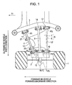
- FIG. 1 is a top view of a suspension device for rear wheels according to a first embodiment.
- FIG. 2 is a schematic view illustrating a disposition of links as seen from the front side of a vehicle.
- the suspension device comprises two lower links 4 and 5 and an upper link 8.
- the lower links 4 and 5 link a lower area of an axle 2, which rotatably supports a wheel 1, and a suspension member 3, which is a vehicle-body side member.
- the upper link 8 links an upper area of the axle 2 and the suspension member 3.
- the two lower links 4 and 5 are mounted to the axle 2 by one elastic bush 9 and one elastic bush 10, respectively, so that the lower links 4 and 5 are swingable vertically relative to the axle 2.
- the two lower links 4 and 5 are linked to the suspension member 3 through one elastic bush 11 and one elastic bush 12, respectively, so that the lower links 4 and 5 are swingable vertically relative to the suspension member 3.
- the upper link 8 is mounted to the axle 2 by one elastic bush 13 so as to be swingable vertically relative to the axle 2, and is linked to the suspension member 3 by one elastic bush 14 so as to be swingable vertically relative to the suspension member 3.
- the two lower links 4 and 5 are disposed substantially in parallel in a vehicle width direction.
- the lower link 4 at the front side in the vehicle forward-backward direction will be called the “front lower link 4”
- the lower link 5 at the rear side in the vehicle forward-backward direction will be called the "rear lower link 5.”
- the elastic bushes 9 to 14 comprise elastic members, formed of rubber, inserted between outer cylinders and respective inner cylinders, and disposed in a nested state.
- the outer cylinder sides are secured to ends of the links 4, 5 and 8, and the inner cylinder sides are mounted to the suspension member 3 or the axle 2 through bolts.
- the front lower link 4 is a rod member extending linearly along a link axial line L1, and the elastic bushes 9 and 11 are provided at mounting portions at the respective ends of the front lower link 4.
- the rear lower link 5 comprises a link body 6 and a projecting portion 7.
- the link body 6 extends along a link axial line L2.
- the projecting portion 7 is integrated with the link body 6 and projects towards the front in the vehicle forward-backward direction, from the link body 6 towards the front lower link 4.
- the projecting portion 7 is a plate member that has a substantially trapezoidal shape in top view.
- the projecting portion 7 need not be a plate member. It may have any structure as long as it projects from the link body 6 towards the front lower link 4.
- An end of the projecting portion 7 is linked to the front lower link 4 through two elastic bushes 20 and 21 and disposed in an offset manner in a vehicle width direction.
- the elastic bushes 20 and 21 are, in top view, disposed with the bush axes being oriented in substantially in the vehicle forward-backward direction (that is, in a direction perpendicular to the link axial line L1).
- the outer cylinders of the bushes 20 and 21 are secured to the front lower link 4, and the inner cylinders of the bushes 20 and 21 are secured to the projecting portion 7 through mounting bolts.
- the front lower link 4 and the rear lower link 5 are, by the elastic bushes 20 and 21 (which are linking portions), linked to each other so as to be swingable three-dimensionally.
- the swinging amounts thereof are restricted to certain amounts due to, for example, the span between the outer and inner cylinders and the rigidity of the elastic members.
- the lower links 4 and 5 are disposed so that the span in the vehicle forward-backward direction between mounting points of the respective lower links 4 and 5 to the axle 2 (hereunder simply referred to as "wheel-side mounting points P2 and P4", respectively) is less than the span in the vehicle forward-backward direction between mounting points of the respective lower links 4 and 5 to the suspension member 3 (hereunder simply referred to as "vehicle-body side mounting points P1 and P3", respectively).
- an intersection P5 of the axial line L1 (connecting the wheel-side mounting point P2 and the vehicle-body side mounting point P1 of the lower link 4) and the axial line L2 (connecting the wheel-side mounting point P4 and the vehicle-body side mounting point P3 of the lower link 5) is further outward than the axle 2 in the vehicle width direction, that is, further outward than the wheel-side mounting points P2 and P4 of the respective lower links 4 and 5 in the vehicle width direction.
- an offset amount of the wheel-side mounting point P2 towards the back in the vehicle forward-backward direction with respect to the vehicle-body side mounting point P1 in the front lower link 4 is larger than an offset amount (substantially zero in FIG. 1 ) of the wheel-side mounting point P4 towards the back in the vehicle forward-backward direction with respect to the vehicle-body side mounting point P3 in the rear lower link 5.
- the tilting of the link axial line L1 of the front lower link 4 towards the back in the vehicle forward-backward direction is larger than the tilting of the link axial line L2 of the rear lower link 5 towards the back in the vehicle forward-backward direction. Due to such a disposition, in top view, the shape defined by connecting four points, that is, the wheel-side mounting points P2 and P4 and the vehicle-body side mounting points P1 and P3 of the respective lower links 4 and 5, is substantially trapezoidal.
- the intersection P5 of the link axial lines L1 and L2 of the respective lower links 4 and 5 is, in top view, disposed behind a center of the wheel 1 (wheel center W/C) in the vehicle front-backward direction.
- the elastic bushes 20 and 21 which constitute the linking portions that swingably link the front lower link 4 and the projecting portion 7 to each other, are called “connect bushes 20 and 21.”
- At least one of the connect bushes 20 and 21 is a fluid-inclusion bush such as that shown in FIGS. 3A and 3B . That is, the bush is formed by interposing an elastic member 21c and two liquid chambers 21d and 21e between an outer cylinder 21a and an inner cylinder 21b, filling the liquid chambers 21d and 21e with a liquid or a fluid (such as a magnetic fluid), and forming an orifice 21f connecting the two liquid chambers 21d and 21e and extending in a circumferential direction.
- the axes of the connect bushes 20 and 21 are set perpendicularly to the link axial line L1 of the front lower link 4, that is, in substantially the vehicle forward-backward direction as mentioned above.
- the wheel-side connect bush 20 be the fluid inclusion bush. This is because an amount of swinging displacement of the wheel-side connect bush 20 is large.
- a resonance peak of the liquid of in the fluid inclusion bush is set at a forward-backward resonance frequency of the suspension and in the vicinity thereof. Accordingly, the fluid inclusion bush becomes an elastic bush having high damping characteristics at the forward-backward resonance frequency of the suspension and in the vicinity thereof.
- the liquid resonance occurs due to a resonance phenomenon when the fluid reciprocates in the orifice 21f.
- the forward-backward resonance frequency of the suspension is determined by, for example, members of the suspension and a layout thereof, it can be previously determined.
- an unbalanced exciting force resulting from a tire or a wheel 1 imbalance is transmitted to the suspension through the axle 2.
- the frequency of this unbalanced exciting force matches the forward-backward resonance frequency of the suspension. This causes the vibration of the suspension to be large, and the vibration is transmitted to a vehicle body through the suspension members, causing the vehicle body to vibrate.
- the suspension vibrates, but the two lower links 4 and 5 vibrate separately so that the connect bushes 20 and 21 linking the two lower links 4 and 5 absorb the vibration of the suspension as a result of repeatedly being deformed from swinging vertically and horizontally (horizontally here means in the vehicle width direction, which is substantially in the direction of the link axial line L1 of the front lower link 4).
- This causes the vibration of the suspension to be reduced.
- the vibration of the suspension is absorbed due to resonance occurring when the fluid in the fluid inclusion bush(s) reciprocates in the orifice 21 f, thereby generating a high damping force.
- the vibration of the suspension is effectively restricted, so that the vibration of the vehicle body that is traveling is restricted.
- FIG. 4 A vibration model according to the embodiment is illustrated in FIG. 4 .
- the results confirmed by the inventor et al. are shown in FIG. 5 .
- Fig. 5 it is understood that by setting a fluid resonance peak at the forward-backward resonance frequency of the suspension or in the vicinity thereof, a vibration level is restricted from reaching the level illustrated by the broken line to the level illustrated by the solid line when the frequency of the unbalanced exciting force matches the forward-backward resonance frequency of the suspension.
- the fluid inclusion bush can be such that fluid resonance occurs at a resonance frequency in a particular narrow range. Therefore, it is possible to reliably set a high damping characteristic with the forward-backward resonance frequency of the suspension and the frequencies in the vicinity thereof being resonance point targets.
- a fluid resistance due to the orifice 21f extending in the circumferential direction can be primarily provided when the bushes 20, 21 flex vertically and in the vehicle width direction. That is, when at least one of the connect bushes 20, 21 generates a damping force as a result of the fluid in the connect bush 20, 21 resonating effectively, it is possible to effectively restrict the vibration of the suspension as mentioned above.
- Linking the two lower links 4 and 5 to each other makes it possible for an input to the wheel 1 in the vehicle forward-backward direction to be received by the two lower links 4 and 5. Therefore, it is not necessary to provide a different link for receiving the input in the vehicle forward-backward direction.
- the two lower links 4 and 5 are linked to each other, but can only swing within a predetermined range because the connect bushes 20 and 21 prevent swinging beyond the predetermined swinging range in at least the vehicle width direction with respect to the input to the wheels 1 in the vehicle forward-backward direction.
- the elastic members of the connect bushes 20 and 21 (linking portions) flex with respect to the input to the wheel 1 in the forward-backward direction (forward-backward input to the wheel center W/C) due to an irregular road surface so that, as shown in FIG. 6 , the inner cylinders of the connect bushes 20 and 21 are swung and displaced in the vehicle width direction while being swung slightly in the vehicle forward-backward direction relative to the outer cylinders of the connect bushes 20 and 21.
- connect bushes 20 and 21 flex with respect to the forward-backward direction input to absorb the input, thereby resulting in damping due to the characteristics of the rubber making up the connect bushes 20 and 21. Therefore, vibration with respect to the input in the forward-backward direction subsides properly.
- the connect bushes 20 and 21 swing vertically and horizontally (horizontally meaning in the vehicle width direction, which is substantially the direction of the link axial line L1 of the front lower link 4) to absorb the vibration.
- the vibration with respect to the input to the wheel 1 in the forward-backward direction (forward-backward input to the wheel center W/C) at a low frequency subsides properly, so that shock when traveling over a protrusion is reduced as mentioned above.
- the rigidity in the forward-backward direction is determined by the rigidity of the connect bushes 20 and 21 so that the degree of design freedom can be increased.
- the rigidity with respect to the input in the forward-backward direction can be set low as a result of the connect bushes 20 and 21 flexing with respect to the forward-backward direction input to the wheels 1. Therefore, even if the two lower links 4 and 5 are linked to each other and are made to receive the forward-backward direction input to the wheel 1 for reducing shock resulting from an irregular road surface, the rigidity of the mounting bushes 9 to 12 (defining the wheel-side mounting points P2 and P4 of the respective two lower links 4 and 5 and the vehicle-body side mounting points P1 and P3 of the respective two lower links 4 and 5) need not be set low. Therefore, the rigidity of the mounting bushes 9 to 12 of the lower links 4 and 5 can be set high.
- the intersection P5 of the link axial lines L1 and L2 of the respective two lower links 4 and 5 is positioned behind the center of the wheel 1 (wheel center W/C) in the vehicle forward-backward direction so that the rotational center of the axle 2 is positioned behind the wheel center W/C. Therefore, with respect to an input in a tire horizontal direction when the vehicle is turning, a torque that causes the turning outer wheel 1 to be oriented in a toe-in direction acts, so that the stability during the turning of the vehicle is increased.
- the wheel-side mounting points P2 and P4 of the respective two lower links 4 and 5 are both swung and displaced by substantially the same amount towards the back in the vehicle forward-backward direction.
- the difference between the displacements of the wheel-side mounting points P2 and P4 of the respective two lower links 4 and 5 in the horizontal direction of the vehicle causes a change in toe to a toe-in direction, so that stability is increased during the braking.
- the link axial line L2 of the rear lower link 5 is set substantially in the vehicle width direction.
- the link axial line L1 of the front lower link 4 is tilted towards the back in the vehicle forward-backward direction so that its wheel-side is set towards the back in the vehicle forward-backward direction.
- the wheel-side mounting points P2 and P4 of the respective two lower links 4 and 5 are swung and displaced by substantially the same amount towards the back in the vehicle forward-backward direction.
- the wheel-side mounting point P2 of the front lower link 4 is pulled further towards the vehicle than the wheel-side mounting point P4 of the rear lower link 5, so that the wheels 1 change to the toe-in direction.
- a liquid inclusion bush is used for at least one of the connect bushes 20 and 21 in the embodiment to obtain a bush that exhibits the highest damping characteristic at the forward-backward resonance frequency of the suspension
- the invention is not limited thereto. Similar effects can be obtained by using a rubber material that can exhibit the highest damping characteristic at at least the forward-backward resonance frequency of the suspension and the vicinity thereof. When there are two or more high-damping frequency peaks due to the characteristics of, for example, the rubber material, one of them is set so as to become the forward-backward resonance frequency of the suspension.
- the fluid resonance peaks of the two connect bushes 20, 21 are set at the same suspension forward-backward resonance frequency and vicinity thereof, the invention is not limited thereto. Namely, the fluid resonance peaks of the respective bushes may be different frequencies.
- the fluid resonance resulting from vertical flexing of one of the connect bushes 20 or 21 may be set at the suspension forward-backward resonance frequency and at the vicinity thereof so that damping characteristics such as those shown in FIG. 7 are provided.
- the fluid resonance peak resulting from flexing of the other connect bush 20 or 21 in the vehicle forward-backward direction is set at a peak value of vibration propagating due to a forward-backward twisting mode of a tire and at the vicinity thereof.
- a vibration model such as that shown in FIG. 8 is provided. Therefore, as shown in FIG. 9 , it is possible to reduce vibration caused by resonance of the suspension resulting from a forward-backward twisting mode of a tire, in addition to reducing vibration caused by resonance of the suspension resulting from an unbalanced exciting force of, for example, a tire.
- the upper link 8 as shown comprises one rod link, it may comprise two or more rod links, or may be one link having a different form, such as an A arm.
- both of the lower links 4 and 5 may be linked to each other at a link axial line L2 side of the rear lower link 5 through the connect bushes 20 and 21.
- the lower link 4 includes a link body 4a and a projecting portion 4b.
- the link body 4a extends along the link axial line L1.
- the projecting portion 4b is integrated with the link body 4a and projects towards the rear in the vehicle forward-backward direction, from the link body 4a towards the rear lower link 5.
- the rear lower link is a rod member extending linearly along the link axial line L2.
- connect bushes 20 and 21 linking the two lower links 4 and 5 need not be disposed on either of the link axial lines L1 and L2 of the respective lower links 4 and 5.
- they may be disposed at intermediate positions between the two lower links 4 and 5.
- the two connect bushes 20, 21 can be disposed in an offset manner in the vehicle width direction.
- the bush 20 or 21 can have a large size in order to have a very high rigidity at frequencies in the road noise region.
- the number of connect bushes 20, 21 linking the two lower links 4 and 5 to each other is not limited to two, so that three or more bushes may be used, or one large bush can be used as described above.
- the link axial line L2 of the rear lower link 5 is disposed in the vehicle width direction, and the link axial line L1 of the front lower link 4 is tilted towards the back in the vehicle forward-backward direction to set the intersection P5 of the link axial lines L1 and L2 of the respective two lower links 4 and 5 further outward than the axle 2 in the vehicle width direction.
- the invention is not limited thereto.
- the intersection P5 of the link axial lines L1 and L2 of the respective two lower links 4 and 5 is still further outward than the axle 2 in the vehicle width direction.
- the axes of the connect bushes 20 and 21 are disposed so as to be oriented substantially in the vehicle forward-backward direction (that is, in a direction perpendicular to the link axial lines L1 and L2), the invention is not limited by this feature.
- the axes of the connect bushes 20 and 21 may be disposed, for example, in the vehicle width direction or along the link axial lines L1 and L2.
- the span in the vehicle forward-backward direction between the mounting points P1 and P3 may be equal to the span between the mounting points P2 and P4, that is, the two lower links 4 and 5 may be set parallel to each other.
- a second embodiment according to the invention differs from the first in that in this second embodiment, elastic bushes satisfying the following Formula (1) are used, where As is the static rigidity for at least one of the connect bushes 20 and 21, Ad is the dynamic rigidity for at least one of the connect bushes 20 and 21 at a high-frequency region at which road noise is generated, Bs is the static rigidity of the mounting bushes 9 to 12, and Bd is the dynamic rigidity of the mounting bushes 9 to 12 at the high-frequency region at which road noise is generated.
- Bs is the static rigidity of the mounting bushes 9 to 12
- Bd is the dynamic rigidity of the mounting bushes 9 to 12 at the high-frequency region at which road noise is generated.
- the bush rigidity characteristics are as shown in FIG. 10 .
- an elastic member having the following characteristics is used as at least one of the connect bushes 20 and 21.
- the rigidity of the connect bush 20, 21 is low with respect to an input at a low-frequency region in the range less than or equal to 25 Hz and for static rigidity, and the rigidity increases as the input frequency is increased. That is, the rigidity is soft with respect to the input at the low-frequency region and is hard with respect to an input at the high-frequency region as illustrated by characteristic B1 in FIG. 10 .
- the mounting bushes 9 to 12 use elastic bushes having the following characteristics. Namely, their rigidity is high with respect to an input at the low-frequency region (hereunder may also be referred to as "ride quality region") in the range less than or equal to 25 Hz and for static rigidity. The rigidity does not increase very much even if the input frequency is increased, so that the gradient thereof is lower than that of the rigidity of the connect bush. This is illustrated by characteristic B2 in FIG. 10 .
- an elastic m ember in which, for example, carbon or mica is mixed in general rubber may be used for the connect bush 20, 21.
- the same material is used for the elastic members of the mounting bushes 9 to 12.
- Road noise is noise that is generated by tires and a road surface when a vehicle is traveling. For example, when a tire vibrates minutely due to an uneven road surface, the vibration is transmitted to the vehicle body through the suspension, as a result of which this vibration becomes noise.
- the lower limit of a frequency band of the high-frequency region is in the range of from 50 to 80 Hz, and the upper limit thereof is in the range of from 400 to 800 Hz.
- a peak frequency band of the road noise is in the range of from 125 to 200 Hz.
- the mounting bushes 9 to 12 are hard (that is, have high rigidity), and the connect bushes 20 and 21 are soft (that is, have low rigidity).
- the rigidity difference between the bushes 20, 21 and 9 to 12 is set large. It is desirable that, in the road noise region (high-frequency region), the rigidity of the connect bushes 20 and 21 be higher.
- the axle 2 constitutes a wheel-side supporting member
- the suspension member 3 constitutes a vehicle-body side member.
- Linking the two lower links 4 and 5 to each other makes it possible for an input to the wheel 1 in the vehicle forward-backward direction to be received by the two lower links 4 and 5. Therefore, it is not necessary to provide a different link for receiving the input in the vehicle forward-backward direction.
- the two lower links 4 and 5 are linked to each other, but can only swing within a predetermined swinging range because the connect bushes 20 and 21 prevent swinging beyond the predetermined swinging range in at least the vehicle width direction with respect to an input to the wheels 1 in the vehicle forward-backward direction.
- the elastic members of the connect bushes 20 and 21 (linking portions) flex with respect to the input to the wheel 1 in the forward-backward direction (forward-backward input to the wheel center W/C) due to an irregular road surface so that, as shown in FIG. 6 , the inner cylinders in the connect bushes 20 and 21 are swung and displaced in the vehicle width direction while being swung slightly in the vehicle forward-backward direction relative to the outer cylinders.
- connect bushes 20 and 21 flex with respect to the forward-backward direction input to absorb the input, thereby resulting in damping due to the characteristics of the rubber making up the connect bushes 20 and 21. Therefore, vibration with respect to the input in the forward-backward direction subsides properly.
- the connect bushes 20 and 21 By setting the rigidity of the connect bushes 20 and 21 low with respect to a low-frequency-region input, such as that when a vehicle travels over a protrusion, the connect bushes 20 and 21 swing vertically and horizontally (horizontal meaning in the vehicle width direction, which is substantially the direction of the link axial line L1 of the front lower link 4), to absorb the vibration.
- the vibration with respect to the input to the wheel 1 in the forward-backward direction forward-backward input to the wheel center at a low frequency
- subsides properly so that shock when traveling over a protrusion is reduced as mentioned above.
- the wheel-side connect bush 20 primarily swings vertically in response to twisting forces
- the connect bushes 20 and 21 primarily swing horizontally in response to shearing forces. This causes the vibration to be absorbed. Therefore, if Formula (1) is satisfied for at least the vertical rigidity and the horizontal rigidity (rigidity substantially in the vehicle width direction, i.e., the rigidity substantially in the direction of the link axial line L1 of the front lower link 4), several advantages can be provided.
- the rigidity with respect to the input in the forward-backward direction can be set low as a result of the connect bushes 20 and 21 flexing with respect to the forward-backward direction input to the wheel 1. Therefore, even though the two lower links 4 and 5 are linked to each other and are made to receive the forward-backward direction input to the wheel 1 to reduce shock resulting from an irregular road surface, the rigidity of the mounting bushes 9 to 12 (defining the wheel-side mounting points P2 and P4 and the vehicle-body side mounting points P1 and P3) need not be set low. In addition, the rigidity of the mounting bushes 9 to 12 of the lower links 4 and 5 is set high, so that the horizontal rigidity (that is, rigidity in the vehicle width direction) of the axle 2 can be made high.
- the forward-backward rigidity of the suspension depends upon the rigidity of the connect bushes 20 and 21.
- the rigidity of the connect bushes 20 and 21 is high. Therefore, by restricting independent swinging between the two lower links 5 when the input frequency is high, that is, by restricting a mode in which the lower links 4 and 5 move separately and roughly, the transmission force of the road noise is reduced, thereby restricting the road noise.
- the intersection P5 of the link axial lines L1 and L2 of the respective two lower links 4 and 5 is positioned behind the center of the wheel 1 (wheel center W/C) in the vehicle forward-backward direction, so that the rotational center of the axle 2 is positioned behind the wheel center W/C. Therefore, with respect to an input in a tire horizontal direction (i.e., the vehicle width direction) when the vehicle is turning, a torque that causes the turning outer wheel 1 to be oriented in a toe-in direction acts so that the stability during the turning of the vehicle is increased.
- the wheel-side mounting points P2 and P4 of the respective two lower links 4 and 5 are both swung and displaced by substantially the same amount towards the back in the vehicle forward-backward direction.
- the difference between the displacements of the wheel-side mounting points P2 and P4 of the respective two lower links 4 and 5 in the horizontal direction (i.e., the vehicle width direction) of the vehicle causes a change in toe to a toe-in direction, so that stability is increased during the braking.
- the link axial line L2 at the rear lower link 5 is set substantially in the vehicle width direction.
- the link axial line L1 at the front lower link 4 is tilted towards the back in the vehicle forward-backward direction so that its wheel-side is set towards the back in the vehicle forward-backward direction.
- the wheel-side mounting points P2 and P4 of the respective two lower links 4 and 5 are swung and displaced by substantially the same amount towards the back in the vehicle forward-backward direction.
- the wheel-side mounting point P2 of the front lower link 4 is pulled further towards the vehicle than the wheel-side mounting point P4 of the rear lower link 5, so that the wheels 1 change to the toe-in direction.
- the upper link 8 comprises one rod link in the described embodiment, the upper link 8 may comprise two or more rod links, or may be one having a different form, such as an A arm.
- both of the lower links 4 and 5 may be linked to each other at a link axial-line L2 side of the rear lower link 5 through the connect bushes 20 and 21.
- connect bushes 20 and 21 linking the two lower links 4 and 5 need not be disposed on either of the link axial lines L1 and L2 of the respective lower links 4 and 5.
- they may be disposed at intermediate positions between the two lower links 4 and 5.
- the two connect bushes 20, 21 are disposed in an offset manner in the vehicle width direction.
- the bush desirably has a large size in order to have a very high rigidity in the road noise region.
- the number of connect bushes 20, 21 linking the two lower links 4 and 5 to each other is not limited to two, so that three or more bushes may be used, or one large bush can be used as described above.
- the link axial line L2 of the rear lower link 5 is disposed in the vehicle width direction and the link axial line L1 of the front lower link 4 is tilted towards the back in the vehicle forward-backward direction to set the intersection P5 of the link axial lines L1 and L2 of the respective two lower links 4 and 5 further outward than the axle 2 in the vehicle width direction
- the invention is not limited thereto.
- the intersection P5 of the link axial lines L1 and L2 of the respective two lower links 4 and 5 is still outward of the axle 2 in the vehicle width direction.
- the axes of the connect bushes 20 and 21 are disposed so as to be oriented substantially in the vehicle forward-backward direction (that is, in a direction perpendicular to the link axial lines L1, L2) in this embodiment.
- the axes of the connect bushes 20 and 21 may be disposed, for example, in the vehicle width direction or along the link axial lines L1 and L2.
- the span in the vehicle forward-backward direction between the mounting points P1 and P3 may be equal to the span between the mounting points P2 and P4, that is, the two lower links 4 and 5 may be set parallel to each other.
- the basic structure of the third embodiment is similar to that of the second embodiment. Parts, etc., similar to those of the above-described embodiments are given the same reference numerals, and are not described in detail.
- the distinctive feature of the third embodiment is the structure of connect bushes 20 and 21.
- the connect bushes 20 and 21 are fluid-inclusion bushes, which are filled with magnetic fluid and are similar in structure to those shown in FIGS. 3A and 3B .
- Each of these bushes is formed by interposing an elastic member 21 c and two liquid chambers 21d and 21e between an outer cylinder 21a and an inner cylinder 21b, by filling the liquid chambers 21d and 21e with the magnetic fluid, and by forming an orifice 21f extending in a circumferential direction. This makes it possible to change the bush rigidity, particularly in a bush axial direction, by changing the viscosity (resistance) of the magnetic fluid.
- a magnetic-force generating member (not shown) is set near the connect bushes 20 and 21.
- the magnetic force generated by the magnetic-force generating member is received by the magnetic fluid, the viscosity of the magnetic fluid is changed, thereby changing the resistance of the fluid passing through the orifice.
- a device that detects a vibration frequency that is generated at the suspension comprises, for example, an acceleration sensor or a velocity sensor mounted to the lower links 4 and 5 and the axle 2, or a gap sensor (relative displacement meter) mounted near the connect bushes 20 and 21.
- FIG. 12 shows an example in which a sensor 30, such as that mentioned above, is provided at the axle 2. The sensor 30 outputs a detection signal to a controller 31.
- the controller 31 can be implemented by, for example, a microcomputer including a random access memory (RAM), a read-only memory (ROM) and a central processing unit (CPU) in addition to various input and output connections.
- RAM random access memory
- ROM read-only memory
- CPU central processing unit
- the control functions described herein are performed by execution by the CPU of one or more software programs stored in ROM.
- some or all of the functions can be implemented by hardware components or a combination of hardware and software.
- the signal from the sensor 30 is input to the controller 31. Based on the signal, which communicates, for example, relative displacement information, acceleration information, and/or vibration velocity information, vibration frequency that is generated at the lower links 4 and 5 is calculated. If a determination is made that the frequency is greater than or equal to a predetermined frequency, such as a frequency of 40 Hz (which is slightly less than the high-frequency band of the road noise area), the magnetic force of the magnetic-force generating member (not shown) is changed to increase the viscosity of the magnetic fluid. This sets the rigidity of the connect bushes 20 and 21 to be high.
- a predetermined frequency such as a frequency of 40 Hz (which is slightly less than the high-frequency band of the road noise area)
- the rigidity of the connect bushes 20 and 21 is dynamically switched as shown in FIG. 13 due to the vibration frequency generated at the suspension or a wheel.
Landscapes
- Engineering & Computer Science (AREA)
- Mechanical Engineering (AREA)
- Vehicle Body Suspensions (AREA)
Abstract
Description
- The present invention relates to a suspension device and method for supporting wheels used on a vehicle. Aspects of the invention relate to an apparatus, to a device, to a method and to a vehicle.
- A related suspension device for rear wheels is discussed in, for example, Japanese Unexamined Patent Application Publication No.
62-234705 - The wheel supporting member and the vehicle-body side member are linked to the ends of the rigid arms by elastic bushes so as to be swingable, thereby allowing a vertical stroke.
- When a vehicle travels, a frequency of an exciting force caused by, for example, an uneven road surface or a wheel imbalance can be transmitted to a suspension device. The suspension device, in turn, can transmit the exciting force to a vehicle body, causing the vehicle body to vibrate.
- It is an aim of the invention to address this issue and to improve upon known technology. Embodiments of the invention may reduce vibration of the vehicle body. Other aims and advantages of the invention will become apparent from the following description, claims and drawings.
- Aspects of the invention therefore provide an apparatus, a method and a vehicle as claimed in the appended claims.
- According to another aspect of the invention for which protection is sought there is provided a suspension device comprising a wheel supporting member configured to rotatably supporting a wheel, two links respectively linking the wheel supporting member and a vehicle-body side member to each other and disposed substantially in parallel in a vehicle width direction, at least one projecting portion extending from at least one of the two links towards the other link and an elastic linking portion linking the projecting portion of one of the links to at least one of the other link and the projecting portion of the other link, the elastic linking portion configured to increase its rigidity with an increasing frequency of a vibration input over a target frequency band.
- In an embodiment, the target frequency band includes a frequency band at which road noise is generated.
- In an embodiment, the target frequency band includes a suspension forward-backward resonance frequency.
- In an embodiment, the elastic linking portion is a fluid inclusion bush comprising a first liquid chamber, a second liquid chamber and a communicating passage, the first liquid chamber and the second liquid chamber being filled with fluid and the communicating passage connecting the first liquid chamber and the second liquid chamber to each other. The target frequency band may includes a resonance frequency of a fluid vibrating system comprising the first liquid chamber, the second liquid cham ber and the communicating passage.
- In an embodiment, the fluid inclusion bush is configured to generate the resonance frequency when the fluid inclusion bush flexes in at least one of a vehicle vertical direction and a vehicle width direction.
- In an embodiment, the elastic linking portion includes a plurality of elastic linking portions having different resonance frequencies.
- The device may comprise link elastic members associated with each of the two links and engaged at respective linking portions where the two links are linked with the wheel supporting member and with the vehicle-body side member. In an embodiment, a rigidity of the link elastic members is greater than the rigidity of the elastic linking portion.
- In an embodiment, the two links include a first link and a second link, the suspension device further comprising a first set of link elastic members at respective linking portions where the first link is linked with the wheel supporting member and with the vehicle-body side member and a second set of link elastic members at respective linking portions where the second link is linked with the wheel supporting member and with the vehicle-body side member.
- In an embodiment, the link elastic members and the elastic linking portion satisfy the following formula:
- (As/Bs) < (Ad/Bd); where Bs is a static rigidity of the link elastic members, Bd is a dynamic rigidity of the link elastic members at a frequency band at which road noise is generated, As is a static rigidity of the elastic linking portion and Ad is a dynamic rigidity of the elastic linking portion at the frequency band at which the road noise is generated.
- In an embodiment, the elastic linking portion includes a plurality of elastic linking portions having different resonance frequencies.
- In an embodiment, the plurality of elastic linking portions includes a plurality of fluid inclusion bushes, each of the plurality of fluid inclusion bushes comprising a first liquid chamber, a second liquid chamber and a communicating passage, the first liquid chamber and the second liquid chamber being filled with fluid and the communicating passage connecting the first liquid chamber and the second liquid chamber to each other; and wherein the target frequency band includes a resonance frequency of a fluid vibrating system comprising the first liquid chamber, the second liquid cham ber and the communicating passage.
- In an embodiment, the two links include a first link and a second link, the suspension device further comprising a first set of link elastic members at respective linking portions where the first link is linked with the wheel supporting member and with the vehicle-body side member and a second set of link elastic members at respective linking portions where the second link is linked with the wheel supporting member and with the vehicle-body side member.
- In an embodiment, a rigidity of each link of the first set of link elastic members and the second set of link elastic members is greater than a rigidity of each of the plurality of elastic linking portions.
- In an embodiment, each link of the first set of link elastic members and the second set of link elastic members and each of the plurality of elastic linking portions satisfy the following formula:
- (As/Bs) < (Ad/Bd); where Bs is a static rigidity of each link elastic member, Bd is a dynamic rigidity of each link elastic member at a frequency band at which road noise is generated, As is a static rigidity of each elastic linking portion and Ad is a dynamic rigidity of each elastic linking portion at the frequency band at which the road noise is generated.
- According to a further aspect of the invention for which protection is sought there is provided a suspension device for a wheel supporting member configured to rotatably support a wheel on a vehicle, the device comprising first linking means for linking the wheel supporting member and a vehicle-body side member, second linking means for linking the wheel supporting member and the vehicle-body side member, the second linking means disposed behind the first linking means in a vehicle forward-backward direction, relative displacement increasing means for increasing a relative displacement between the first linking means and the second linking means, reaction force generating means for generating a damping force in accordance with the relative displacement and
reaction force adjusting means for increasing the damping force as a frequency of a periodic displacement included in the relative displacement increases. - According to a still further aspect of the invention for which protection is sought there is provided a method of suspending a wheel rotatably supported by a wheel supporting member, the method comprising displacing two links relative to each other in accordance with a displacement of the wheel supporting member in a vehicle forward-backward direction, the two links linking the wheel supporting member and a vehicle-body side member to each other and disposed substantially in parallel in the vehicle width direction, generating a damping force in accordance with relative displacement and increasing the damping force as a frequency of a periodic displacement included in the relative displacement increases.
- According to one example of a suspension device taught herein, a wheel supporting member is configured to rotatably support a wheel, two links respectively link the wheel supporting member and a vehicle-body side member to each other and are disposed substantially in parallel in a vehicle width direction and at least one projecting portion extends from at least one of the two links towards the other link. In this example, an elastic linking portion links the projecting portion of one of the links to the other link and/or the projecting portion of the other link and is configured to increase its rigidity with an increasing frequency of a vibration input over a target frequency band.
- According to another example of a suspension device for a wheel supporting member configured to rotatably support a wheel on a vehicle, the device comprises first linking means for linking the wheel supporting member and a vehicle-body side member and second linking means for linking the wheel supporting member and the vehicle-body side member. The second linking means is disposed behind the first linking means in a vehicle forward-backward direction. The device according to this exam pie also includes relative displacement increasing means for increasing a relative displacem ent between the first linking means and the second linking means, reaction force generating means for generating a damping force in accordance with the relative displacement and reaction force adjusting means for increasing the damping force as a frequency of a periodic displacement included in the relative displacement increases.
- One example of a method of suspending a wheel rotatably supported by a wheel supporting member taught herein comprises displacing two links relative to each other in accordance with a displacement of the wheel supporting member in a vehicle forward-backward direction, the two links linking the wheel supporting member and a vehicle-body side member to each other and disposed substantially in parallel in the vehicle width direction, generating a damping force in accordance with relative displacement and increasing the damping force as a frequency of a periodic displacement included in the relative displacement increases.
- Within the scope of this application it is envisaged that the various aspects, embodiments, examples, features and alternatives set out in the preceding paragraphs, in the claims and/or in the following description and drawings may be taken individually or in any combination thereof.
- The present invention will now be described, by way of example only, with reference to the accompanying drawings in which:
-
FIG. 1 is a top view of a suspension device for rear wheels according to an embodiment; -
FIG. 2 is a schematic view, as seen from the front of a vehicle, of a disposition and structure of links in the suspension device for rear wheels according to the embodiment ofFIG. 1 ; -
FIGS. 3A and 3B illustrate an example structure of connect bushes; -
FIG. 4 shows a vibration model according to the embodiment ofFIG. 1 ; -
FIG. 5 is a graph showing a damping effect; -
FIG. 6 is a top view of a behavior with respect to an input in a vehicle forward-backward direction; -
FIG. 7 is a graph of example damping characteristics of the connect bushes; -
FIG. 8 shows another vibration model; -
FIG. 9 is a graph showing a damping effect; -
FIG. 10 is a graph showing example rigidity characteristics of elastic bushes; -
FIG. 11 is a top view of a suspension device for vehicle wheels according to a variation in embodiments of the invention; -
FIG. 12 is a top view of a suspension device for rear wheels according to a third embodiment of the invention; and -
FIG. 13 is a graph showing an example rigidity characteristic of an elastic bush. -
FIG. 1 is a top view of a suspension device for rear wheels according to a first embodiment.FIG. 2 is a schematic view illustrating a disposition of links as seen from the front side of a vehicle. - The suspension device comprises two
lower links upper link 8. Thelower links axle 2, which rotatably supports awheel 1, and a suspension member 3, which is a vehicle-body side member. Theupper link 8 links an upper area of theaxle 2 and the suspension member 3. - The two
lower links axle 2 by oneelastic bush 9 and oneelastic bush 10, respectively, so that thelower links axle 2. The twolower links elastic bush 11 and oneelastic bush 12, respectively, so that thelower links upper link 8 is mounted to theaxle 2 by oneelastic bush 13 so as to be swingable vertically relative to theaxle 2, and is linked to the suspension member 3 by oneelastic bush 14 so as to be swingable vertically relative to the suspension member 3. - The two
lower links lower links lower link 4 at the front side in the vehicle forward-backward direction will be called the "frontlower link 4," and thelower link 5 at the rear side in the vehicle forward-backward direction will be called the "rearlower link 5." - The
elastic bushes 9 to 14 comprise elastic members, formed of rubber, inserted between outer cylinders and respective inner cylinders, and disposed in a nested state. In the embodiment, the outer cylinder sides are secured to ends of thelinks axle 2 through bolts. - The front
lower link 4 is a rod member extending linearly along a link axial line L1, and theelastic bushes lower link 4. - The rear
lower link 5 comprises alink body 6 and a projectingportion 7. Thelink body 6 extends along a link axial line L2. The projectingportion 7 is integrated with thelink body 6 and projects towards the front in the vehicle forward-backward direction, from thelink body 6 towards the frontlower link 4. In this embodiment, the projectingportion 7 is a plate member that has a substantially trapezoidal shape in top view. The projectingportion 7 need not be a plate member. It may have any structure as long as it projects from thelink body 6 towards the frontlower link 4. - An end of the projecting
portion 7 is linked to the frontlower link 4 through twoelastic bushes elastic bushes bushes lower link 4, and the inner cylinders of thebushes portion 7 through mounting bolts. Accordingly, the frontlower link 4 and the rearlower link 5 are, by theelastic bushes 20 and 21 (which are linking portions), linked to each other so as to be swingable three-dimensionally. In addition, the swinging amounts thereof are restricted to certain amounts due to, for example, the span between the outer and inner cylinders and the rigidity of the elastic members. - In addition, in top view, the
lower links lower links lower links axle 2 in the vehicle width direction, that is, further outward than the wheel-side mounting points P2 and P4 of the respectivelower links FIG. 1 , in top view, an offset amount of the wheel-side mounting point P2 towards the back in the vehicle forward-backward direction with respect to the vehicle-body side mounting point P1 in the frontlower link 4 is larger than an offset amount (substantially zero inFIG. 1 ) of the wheel-side mounting point P4 towards the back in the vehicle forward-backward direction with respect to the vehicle-body side mounting point P3 in the rearlower link 5. In addition, in the embodiment shown inFIG. 1 , in top view, the tilting of the link axial line L1 of the frontlower link 4 towards the back in the vehicle forward-backward direction is larger than the tilting of the link axial line L2 of the rearlower link 5 towards the back in the vehicle forward-backward direction. Due to such a disposition, in top view, the shape defined by connecting four points, that is, the wheel-side mounting points P2 and P4 and the vehicle-body side mounting points P1 and P3 of the respectivelower links - Accordingly, as a result of setting the offset amount of the wheel-side mounting point P2 of the front
lower link 4 with respect to the vehicle-body side mounting point P1 of the frontlower link 4 towards the back in the vehicle forward-backward direction greater than the offset amount of the wheel-side mounting point P4 of the rearlower link 5 with respect to the vehicle-body side mounting point P3 of the rearlower link 5 towards the back in the vehicle forward-backward direction, the intersection P5 of the link axial lines L1 and L2 of the respectivelower links - The
elastic bushes lower link 4 and the projectingportion 7 to each other, are called "connectbushes elastic bushes 9 to 12, which link thelower links axle 2 and the suspension member 3, are called "mountingbushes 9 to 12." - At least one of the
connect bushes FIGS. 3A and 3B . That is, the bush is formed by interposing anelastic member 21c and twoliquid chambers outer cylinder 21a and aninner cylinder 21b, filling theliquid chambers orifice 21f connecting the twoliquid chambers connect bushes lower link 4, that is, in substantially the vehicle forward-backward direction as mentioned above. - Here, when only one of the
connect bushes side connect bush 20 be the fluid inclusion bush. This is because an amount of swinging displacement of the wheel-side connect bush 20 is large. - In addition, a resonance peak of the liquid of in the fluid inclusion bush is set at a forward-backward resonance frequency of the suspension and in the vicinity thereof. Accordingly, the fluid inclusion bush becomes an elastic bush having high damping characteristics at the forward-backward resonance frequency of the suspension and in the vicinity thereof.
- Here, the liquid resonance occurs due to a resonance phenomenon when the fluid reciprocates in the
orifice 21f. - Since the forward-backward resonance frequency of the suspension is determined by, for example, members of the suspension and a layout thereof, it can be previously determined.
- With a conventional suspension, an unbalanced exciting force resulting from a tire or a
wheel 1 imbalance is transmitted to the suspension through theaxle 2. In addition, at a predetermined vehicle speed, the frequency of this unbalanced exciting force matches the forward-backward resonance frequency of the suspension. This causes the vibration of the suspension to be large, and the vibration is transmitted to a vehicle body through the suspension members, causing the vehicle body to vibrate. - In contrast, in the embodiment, the suspension vibrates, but the two
lower links connect bushes lower links orifice 21 f, thereby generating a high damping force. As a result, the vibration of the suspension is effectively restricted, so that the vibration of the vehicle body that is traveling is restricted. - A vibration model according to the embodiment is illustrated in
FIG. 4 . The results confirmed by the inventor et al. are shown inFIG. 5 . As shown inFig. 5 , it is understood that by setting a fluid resonance peak at the forward-backward resonance frequency of the suspension or in the vicinity thereof, a vibration level is restricted from reaching the level illustrated by the broken line to the level illustrated by the solid line when the frequency of the unbalanced exciting force matches the forward-backward resonance frequency of the suspension. - In addition, the fluid inclusion bush can be such that fluid resonance occurs at a resonance frequency in a particular narrow range. Therefore, it is possible to reliably set a high damping characteristic with the forward-backward resonance frequency of the suspension and the frequencies in the vicinity thereof being resonance point targets.
- Since the axes of the
connect bushes lower link 4, that is, the axes of theconnect bushes orifice 21f extending in the circumferential direction can be primarily provided when thebushes connect bushes connect bush - When the two
lower links wheel 1, a swinging behavior of theconnect bushes side connect bush 20 swings primarily vertically in response to twisting and primarily horizontally in response to shearing forces, thereby absorbing the vibration. - Linking the two
lower links wheel 1 in the vehicle forward-backward direction to be received by the twolower links - The two
lower links connect bushes wheels 1 in the vehicle forward-backward direction. - The elastic members of the
connect bushes 20 and 21 (linking portions) flex with respect to the input to thewheel 1 in the forward-backward direction (forward-backward input to the wheel center W/C) due to an irregular road surface so that, as shown inFIG. 6 , the inner cylinders of theconnect bushes connect bushes lower links lower links 4 and 5) are connected to be changed as seen in the top view so that the rigidity in the vehicle forward-backward direction of theaxle 2 supported at the two linkedlower links - In addition, the
connect bushes connect bushes - If the rigidity of the
connect bushes connect bushes wheel 1 in the forward-backward direction (forward-backward input to the wheel center W/C) at a low frequency subsides properly, so that shock when traveling over a protrusion is reduced as mentioned above. - Accordingly, even if the
lower links connect bushes - The rigidity with respect to the input in the forward-backward direction can be set low as a result of the
connect bushes wheels 1. Therefore, even if the twolower links wheel 1 for reducing shock resulting from an irregular road surface, the rigidity of the mountingbushes 9 to 12 (defining the wheel-side mounting points P2 and P4 of the respective twolower links lower links 4 and 5) need not be set low. Therefore, the rigidity of the mountingbushes 9 to 12 of thelower links bushes 9 to 12 set high, horizontal rigidity (that is, rigidity in the vehicle width direction) of theaxle 2 can be made high. In addition, this results in increasing the rigidity of a camber, so that steering stability can be increased. Since the horizontal input to thewheel 1 is applied to the twolower links connect bushes axle 2 is not set low. As a result, the rigidity in the forward-backward direction can be set low and the horizontal rigidity can be set high, so that the ride quality can be improved and the steering stability can be increased. - In top view, the intersection P5 of the link axial lines L1 and L2 of the respective two
lower links axle 2 is positioned behind the wheel center W/C. Therefore, with respect to an input in a tire horizontal direction when the vehicle is turning, a torque that causes the turningouter wheel 1 to be oriented in a toe-in direction acts, so that the stability during the turning of the vehicle is increased. - In top view, since the intersection P5 of the link axial lines L1 and L2 of the respective two linked
lower links axle 2 in the vehicle width direction, that is, since the span between the wheel-side mounting points P2 and P4 is set narrower than the span between the vehicle-body side mounting points P1 and P3 in the vehicle forward-backward direction, several advantages are provided. - First, when an input in the backward direction in the vehicle forward-backward direction is made to the ground-contact face of the
wheel 1 due to, for example, braking, the wheel-side mounting points P2 and P4 of the respective twolower links lower links - Further, in the embodiment shown in
FIG. 1 , the link axial line L2 of the rearlower link 5 is set substantially in the vehicle width direction. The link axial line L1 of the frontlower link 4 is tilted towards the back in the vehicle forward-backward direction so that its wheel-side is set towards the back in the vehicle forward-backward direction. As a result, the wheel-side mounting points P2 and P4 of the respective twolower links lower link 4 is pulled further towards the vehicle than the wheel-side mounting point P4 of the rearlower link 5, so that thewheels 1 change to the toe-in direction. - Although a liquid inclusion bush is used for at least one of the
connect bushes - Although the fluid resonance peaks of the two connect
bushes connect bushes FIG. 7 are provided. In addition, the fluid resonance peak resulting from flexing of theother connect bush - In this case, a vibration model such as that shown in
FIG. 8 is provided. Therefore, as shown inFIG. 9 , it is possible to reduce vibration caused by resonance of the suspension resulting from a forward-backward twisting mode of a tire, in addition to reducing vibration caused by resonance of the suspension resulting from an unbalanced exciting force of, for example, a tire. - Although the
upper link 8 as shown comprises one rod link, it may comprise two or more rod links, or may be one link having a different form, such as an A arm. - In addition, as shown in
FIG. 11 , both of thelower links lower link 5 through theconnect bushes lower link 4 includes alink body 4a and a projectingportion 4b. Thelink body 4a extends along the link axial line L1. The projectingportion 4b is integrated with thelink body 4a and projects towards the rear in the vehicle forward-backward direction, from thelink body 4a towards the rearlower link 5. The rear lower link is a rod member extending linearly along the link axial line L2. - Further, the
connect bushes lower links lower links lower links - In addition, it is possible to project projecting
portions 7 separately from thelower link 4 to thelower link 5 and from thelower link 5 to thelower link 4, set one linking portion each on the axial lines of thelower links connect bushes - Even in this case, as viewed from the front of a vehicle, the two connect
bushes connect bush bush - The number of
connect bushes lower links - In the above-described embodiment, the link axial line L2 of the rear
lower link 5 is disposed in the vehicle width direction, and the link axial line L1 of the frontlower link 4 is tilted towards the back in the vehicle forward-backward direction to set the intersection P5 of the link axial lines L1 and L2 of the respective twolower links axle 2 in the vehicle width direction. However, the invention is not limited thereto. For example, it is possible to dispose the link axial line L1 of the frontlower link 4 in substantially the vehicle width direction and to tilt the link axial line L2 of the rearlower link 5 in the forward direction so that the wheel-side mounting point P4 is disposed more towards the front in the vehicle forward-backward direction than the vehicle-body side mounting point P3. With this arrangement, the intersection P5 of the link axial lines L1 and L2 of the respective twolower links axle 2 in the vehicle width direction. - Although the axes of the
connect bushes connect bushes bushes bushes - Further, the span in the vehicle forward-backward direction between the mounting points P1 and P3 may be equal to the span between the mounting points P2 and P4, that is, the two
lower links - A second embodiment according to the invention differs from the first in that in this second embodiment, elastic bushes satisfying the following Formula (1) are used, where As is the static rigidity for at least one of the
connect bushes connect bushes bushes 9 to 12, and Bd is the dynamic rigidity of the mountingbushes 9 to 12 at the high-frequency region at which road noise is generated. When only one of theconnect bushes 
- The bush rigidity characteristics are as shown in
FIG. 10 . For example, an elastic member having the following characteristics is used as at least one of theconnect bushes connect bush FIG. 10 . - The mounting
bushes 9 to 12 use elastic bushes having the following characteristics. Namely, their rigidity is high with respect to an input at the low-frequency region (hereunder may also be referred to as "ride quality region") in the range less than or equal to 25 Hz and for static rigidity. The rigidity does not increase very much even if the input frequency is increased, so that the gradient thereof is lower than that of the rigidity of the connect bush. This is illustrated by characteristic B2 inFIG. 10 . - If the rigidities are set in this way, Formula (1) is satisfied.
- More specifically, to satisfy the condition of Formula (1), an elastic m ember in which, for example, carbon or mica is mixed in general rubber may be used for the
connect bush bushes 9 to 12. - Here, in the high-frequency region (road noise region) where road noise is generated, even if the dynamic rigidity of the mounting
bushes 9 to 12 is lower than the dynamic rigidity of theconnect bushes - Road noise is noise that is generated by tires and a road surface when a vehicle is traveling. For example, when a tire vibrates minutely due to an uneven road surface, the vibration is transmitted to the vehicle body through the suspension, as a result of which this vibration becomes noise.
- Though dependent upon the vehicle, in general, the lower limit of a frequency band of the high-frequency region (road noise region) is in the range of from 50 to 80 Hz, and the upper limit thereof is in the range of from 400 to 800 Hz. In general, a peak frequency band of the road noise is in the range of from 125 to 200 Hz.
- With respect to an input at the ride quality region (low-frequency region) and for static rigidity, the mounting
bushes 9 to 12 are hard (that is, have high rigidity), and theconnect bushes bushes connect bushes - Here, the
axle 2 constitutes a wheel-side supporting member, and the suspension member 3 constitutes a vehicle-body side member. - Linking the two
lower links wheel 1 in the vehicle forward-backward direction to be received by the twolower links - The two
lower links connect bushes wheels 1 in the vehicle forward-backward direction. - The elastic members of the
connect bushes 20 and 21 (linking portions) flex with respect to the input to thewheel 1 in the forward-backward direction (forward-backward input to the wheel center W/C) due to an irregular road surface so that, as shown inFIG. 6 , the inner cylinders in theconnect bushes axle 2 supported at the two linkedlower links - In addition, the
connect bushes connect bushes - By setting the rigidity of the
connect bushes connect bushes wheel 1 in the forward-backward direction (forward-backward input to the wheel center at a low frequency) subsides properly, so that shock when traveling over a protrusion is reduced as mentioned above. - Regarding the swinging of the
connect bushes side connect bush 20 primarily swings vertically in response to twisting forces, and theconnect bushes - First, even if the
lower links connect bushes - Next, the rigidity with respect to the input in the forward-backward direction can be set low as a result of the
connect bushes wheel 1. Therefore, even though the twolower links wheel 1 to reduce shock resulting from an irregular road surface, the rigidity of the mountingbushes 9 to 12 (defining the wheel-side mounting points P2 and P4 and the vehicle-body side mounting points P1 and P3) need not be set low. In addition, the rigidity of the mountingbushes 9 to 12 of thelower links axle 2 can be made high. This results in increasing the rigidity of a camber, so that steering stability can be increased. Since the horizontal input to thewheel 1 is applied to the twolower links connect bushes axle 2 is not set low. As a result, the rigidity in the forward-backward direction can be set low and the horizontal rigidity can be set high, so that the ride quality can be improved and the steering stability can be increased. - As mentioned above, the forward-backward rigidity of the suspension depends upon the rigidity of the
connect bushes connect bushes lower links 5 when the input frequency is high, that is, by restricting a mode in which thelower links - In top view, the intersection P5 of the link axial lines L1 and L2 of the respective two
lower links axle 2 is positioned behind the wheel center W/C. Therefore, with respect to an input in a tire horizontal direction (i.e., the vehicle width direction) when the vehicle is turning, a torque that causes the turningouter wheel 1 to be oriented in a toe-in direction acts so that the stability during the turning of the vehicle is increased. - Since the intersection P5 of the link axial lines L1 and L2 of the respective two linked
lower links axle 2 in the vehicle width direction, that is, since in the vehicle forward-backward direction, the span between the wheel-side mounting points P2 and P4 is set narrower than the span between the vehicle-body side mounting points P1 and P3, several advantages are provided. - First, when an input in the backward direction in the vehicle forward-backward direction is made to the ground-contact face of the
wheel 1 due to, for example, braking, the wheel-side mounting points P2 and P4 of the respective twolower links lower links - Further, in the embodiment shown in
FIG. 1 , the link axial line L2 at the rearlower link 5 is set substantially in the vehicle width direction. The link axial line L1 at the frontlower link 4 is tilted towards the back in the vehicle forward-backward direction so that its wheel-side is set towards the back in the vehicle forward-backward direction. As a result, the wheel-side mounting points P2 and P4 of the respective twolower links lower link 4 is pulled further towards the vehicle than the wheel-side mounting point P4 of the rearlower link 5, so that thewheels 1 change to the toe-in direction. - Accordingly, it is possible to at least improve ride quality and increase steering stability, and to reduce vibration.
- Although the
upper link 8 comprises one rod link in the described embodiment, theupper link 8 may comprise two or more rod links, or may be one having a different form, such as an A arm. - In addition, as shown in
FIG. 11 and as described above with respect to the first embodiment, both of thelower links lower link 5 through theconnect bushes - Further, the
connect bushes lower links lower links lower links - It is also possible to project projecting
portions 7 separately from thelower link 4 to thelower link 5 and from thelower link 5 to thelower link 4, set one linking portion each on the axial lines of thelower links connect bushes - As previously described, as viewed from the front of a vehicle, the two connect
bushes - The number of
connect bushes lower links - Although the link axial line L2 of the rear
lower link 5 is disposed in the vehicle width direction and the link axial line L1 of the frontlower link 4 is tilted towards the back in the vehicle forward-backward direction to set the intersection P5 of the link axial lines L1 and L2 of the respective twolower links axle 2 in the vehicle width direction, the invention is not limited thereto. For example, it is possible to dispose the link axial line L1 of the frontlower link 4 in substantially the vehicle width direction and to tilt the link axial line L2 of the rearlower link 5 in the forward direction so that the wheel-side mounting point 4 is disposed more towards the front in the vehicle forward-backward direction than the vehicle-body side mounting point P3. The intersection P5 of the link axial lines L1 and L2 of the respective twolower links axle 2 in the vehicle width direction. - The axes of the
connect bushes connect bushes bushes bushes - Further, the span in the vehicle forward-backward direction between the mounting points P1 and P3 may be equal to the span between the mounting points P2 and P4, that is, the two
lower links - The basic structure of the third embodiment is similar to that of the second embodiment. Parts, etc., similar to those of the above-described embodiments are given the same reference numerals, and are not described in detail. The distinctive feature of the third embodiment is the structure of
connect bushes - In the embodiment, the
connect bushes FIGS. 3A and 3B . Each of these bushes is formed by interposing anelastic member 21 c and twoliquid chambers outer cylinder 21a and aninner cylinder 21b, by filling theliquid chambers orifice 21f extending in a circumferential direction. This makes it possible to change the bush rigidity, particularly in a bush axial direction, by changing the viscosity (resistance) of the magnetic fluid. - Further, a magnetic-force generating member (not shown) is set near the
connect bushes - A device that detects a vibration frequency that is generated at the suspension is provided. This device comprises, for example, an acceleration sensor or a velocity sensor mounted to the
lower links axle 2, or a gap sensor (relative displacement meter) mounted near theconnect bushes FIG. 12 shows an example in which asensor 30, such as that mentioned above, is provided at theaxle 2. Thesensor 30 outputs a detection signal to acontroller 31. - The
controller 31 can be implemented by, for example, a microcomputer including a random access memory (RAM), a read-only memory (ROM) and a central processing unit (CPU) in addition to various input and output connections. Generally, the control functions described herein are performed by execution by the CPU of one or more software programs stored in ROM. Of course, some or all of the functions can be implemented by hardware components or a combination of hardware and software. - The signal from the
sensor 30 is input to thecontroller 31. Based on the signal, which communicates, for example, relative displacement information, acceleration information, and/or vibration velocity information, vibration frequency that is generated at thelower links connect bushes - Thus, the rigidity of the
connect bushes FIG. 13 due to the vibration frequency generated at the suspension or a wheel. - The other structural features and the operational advantages of the third embodiment are similar to those of the second embodiment.
- The above-described embodiments have been described in order to allow easy understanding of the invention and do not limit the invention. On the contrary, the invention is intended to cover various modifications and equivalent arrangements included within the scope of the appended claims, which scope is to be accorded the broadest interpretation so as to encompass all such modifications and equivalent structure as is permitted under the law.
- This application claims priority from Japanese Patent Application Nos.
2007-098528, filed 4th April 2007 2007-208897, filed 10th August 2007
Claims (12)
- A suspension apparatus for a wheel supporting member configured to rotatably support a wheel on a vehicle, the apparatus comprising:first and second links for linking the wheel supporting member and a vehicle-body side member to each other, the first and second links being disposed substantially in parallel in a vehicle width direction;at least one projecting portion extending from one of the two links towards the other link; andan elastic linking portion linking the projecting portion of one of the links to at least one of the other link and a projecting portion of the other link, the elastic linking portion being arranged to increase its rigidity with an increasing frequency of a vibration input over a target frequency band.
- An apparatus as claimed in claim 1 wherein the target frequency band comprises:a frequency band at which road noise is generated; and/ora suspension forward-backward resonance frequency.
- An apparatus as claimed in claim 1 or claim 2 wherein the elastic linking portion comprises a plurality of elastic linking portions having different resonance frequencies.
- An apparatus as claimed in claim 1 or claim 2:wherein the or each elastic linking portion comprises a fluid inclusion bush comprising a first liquid chamber, a second liquid chamber and a communicating passage, the first liquid chamber and the second liquid chamber being filled with fluid and the communicating passage connecting the first liquid chamber and the second liquid chamber to each other; andwherein the target frequency band includes a resonance frequency of a fluid vibrating system comprising the first liquid chamber, the second liquid cham ber and the communicating passage.
- An apparatus as claimed in claim 4, wherein the or each fluid inclusion bush is arranged to generate the resonance frequency when it flexes in at least one of a vehicle vertical direction and a vehicle width direction.
- An apparatus as claimed in any preceding claim, comprising link elastic members associated with each of the two links and engaged at respective linking portions where the two links are linked with the wheel supporting member and with the vehicle-body side member, wherein a rigidity of the link elastic members is greater than the rigidity of the elastic linking portion.
- An apparatus as claimed in any preceding claim, comprising:a first set of link elastic members at respective linking portions where the first link is linked with the wheel supporting member and with the vehicle-body side member; anda second set of link elastic members at respective linking portions where the second link is linked with the wheel supporting member and with the vehicle-body side member.
- An apparatus as claimed in claim 7, wherein a rigidity of each link of the first set of link elastic members and the second set of link elastic members is greater than a rigidity of each of the plurality of elastic linking portions.
- An apparatus as claimed in claim 7 or claim 8, wherein each link of the first set of link elastic members and the second set of link elastic members and each of the plurality of elastic linking portions satisfy the formula (As/Bs) < (Ad/Bd); wherein
Bs is a static rigidity of each link elastic member;
Bd is a dynamic rigidity of each link elastic member at a frequency band at which road noise is generated;
As is a static rigidity of each elastic linking portion; and
Ad is a dynamic rigidity of each elastic linking portion at the frequency band at which the road noise is generated. - A suspension apparatus for a wheel supporting member configured to rotatably support a wheel on a vehicle, the apparatus comprising:first link means for linking the wheel supporting member and a vehicle-body side member;second link means for linking the wheel supporting member and the vehicle-body side member, the second link means being disposed behind the first linking means in a vehicle longitudinal direction;displacement means for increasing a relative displacement between the first link means and the second link means;reaction force generation means for generating a damping force in accordance with the relative displacement; andreaction force adjustment means for increasing the damping force as a frequency of a periodic displacement o the relative displacement increases.
- A method of suspending a wheel rotatably supported by a wheel supporting member, the method comprising:displacing two links relative to each other in accordance with a displacement of the wheel supporting member in a vehicle longitudinal direction, the two links linking the wheel supporting member and a vehicle-body side member to each other and disposed substantially in parallel in the vehicle width direction;generating a damping force in accordance with relative displacement; andincreasing the damping force as a frequency of a periodic displacement included in the relative displacement increases.
- A vehicle having an apparatus as claimed in any of claims 1 to 10.
Applications Claiming Priority (2)
| Application Number | Priority Date | Filing Date | Title |
|---|---|---|---|
| JP2007098528A JP4893430B2 (en) | 2007-04-04 | 2007-04-04 | Rear wheel suspension system |
| JP2007208897A JP4998136B2 (en) | 2007-08-10 | 2007-08-10 | Rear wheel suspension system |
Publications (2)
| Publication Number | Publication Date |
|---|---|
| EP1977916A1 true EP1977916A1 (en) | 2008-10-08 |
| EP1977916B1 EP1977916B1 (en) | 2011-06-22 |
Family
ID=39564761
Family Applications (1)
| Application Number | Title | Priority Date | Filing Date |
|---|---|---|---|
| EP08153984A Ceased EP1977916B1 (en) | 2007-04-04 | 2008-04-02 | Suspension device and method for supporting wheels |
Country Status (2)
| Country | Link |
|---|---|
| US (1) | US7789406B2 (en) |
| EP (1) | EP1977916B1 (en) |
Families Citing this family (8)
| Publication number | Priority date | Publication date | Assignee | Title |
|---|---|---|---|---|
| US8690177B2 (en) * | 2012-08-16 | 2014-04-08 | Ford Global Technologies, Llc | Front wheel suspension for a motor vehicle |
| KR20120013459A (en) * | 2007-03-29 | 2012-02-14 | 닛산 지도우샤 가부시키가이샤 | Vehicle suspension system |
| EP2129536B1 (en) * | 2007-04-04 | 2016-06-15 | Nissan Motor Co., Ltd. | Vehicle suspension device |
| JP5293770B2 (en) | 2011-05-16 | 2013-09-18 | 日産自動車株式会社 | Suspension structure, suspension link arrangement method |
| US8628101B2 (en) * | 2011-05-16 | 2014-01-14 | Nissan Motor Co., Ltd. | Suspension structure, bush structure and suspension characteristic adjusting method |
| DE102012200001A1 (en) * | 2012-01-02 | 2013-07-04 | Ford Global Technologies, Llc | Rubber-metal bearing for trapezoidal-link in wheel suspension, has rubber elastic body fastened and arranged between outer bush and inner bush, where outer bush has front end surface at which leading elastic damping element is mounted |
| US9127743B2 (en) | 2013-04-05 | 2015-09-08 | Zhongli North America, Inc. | Chassis bushing with integrated travel limiter |
| WO2015138571A1 (en) | 2014-03-11 | 2015-09-17 | Rush University Medical Center | Metal-ion electrochemical biosensor and use thereof |
Citations (5)
| Publication number | Priority date | Publication date | Assignee | Title |
|---|---|---|---|---|
| US4681342A (en) * | 1985-04-24 | 1987-07-21 | Dr. Ing. H.C.F. Porsche Aktiengesellschaft | Wheel suspension |
| JPS62234705A (en) | 1986-04-03 | 1987-10-15 | Toyota Motor Corp | Suspension device of automobile |
| US4822010A (en) * | 1987-09-30 | 1989-04-18 | Lord Corporation | Fluid filled resilient bushing |
| JP2007098528A (en) | 2005-10-06 | 2007-04-19 | Murata Mach Ltd | Spindle pickup lathe |
| JP2007208897A (en) | 2006-02-06 | 2007-08-16 | Sony Corp | Information processing apparatus, information recording medium manufacturing apparatus, information recording medium and method, and computer program |
Family Cites Families (3)
| Publication number | Priority date | Publication date | Assignee | Title |
|---|---|---|---|---|
| DE2256358A1 (en) * | 1972-11-17 | 1974-05-30 | Porsche Ag | WHEEL SUSPENSION FOR VEHICLES WITH ELASTIC TOE-IN |
| JP2924306B2 (en) * | 1991-06-03 | 1999-07-26 | 日産自動車株式会社 | Wheel independent suspension |
| KR20120013459A (en) * | 2007-03-29 | 2012-02-14 | 닛산 지도우샤 가부시키가이샤 | Vehicle suspension system |
-
2008
- 2008-03-31 US US12/058,959 patent/US7789406B2/en not_active Expired - Fee Related
- 2008-04-02 EP EP08153984A patent/EP1977916B1/en not_active Ceased
Patent Citations (6)
| Publication number | Priority date | Publication date | Assignee | Title |
|---|---|---|---|---|
| US4681342A (en) * | 1985-04-24 | 1987-07-21 | Dr. Ing. H.C.F. Porsche Aktiengesellschaft | Wheel suspension |
| JPS62234705A (en) | 1986-04-03 | 1987-10-15 | Toyota Motor Corp | Suspension device of automobile |
| US4772043A (en) * | 1986-04-03 | 1988-09-20 | Toyota Jidosha Kabushiki Kaisha | Suspension for automobile |
| US4822010A (en) * | 1987-09-30 | 1989-04-18 | Lord Corporation | Fluid filled resilient bushing |
| JP2007098528A (en) | 2005-10-06 | 2007-04-19 | Murata Mach Ltd | Spindle pickup lathe |
| JP2007208897A (en) | 2006-02-06 | 2007-08-16 | Sony Corp | Information processing apparatus, information recording medium manufacturing apparatus, information recording medium and method, and computer program |
Also Published As
| Publication number | Publication date |
|---|---|
| EP1977916B1 (en) | 2011-06-22 |
| US7789406B2 (en) | 2010-09-07 |
| US20080246243A1 (en) | 2008-10-09 |
Similar Documents
| Publication | Publication Date | Title |
|---|---|---|
| EP1977916B1 (en) | Suspension device and method for supporting wheels | |
| EP2129537B1 (en) | Suspension device for a wheel and method for supporting a wheel | |
| US8342542B2 (en) | Suspension device and method for supporting a wheel | |
| US8056912B2 (en) | Multi-link suspension device and method for suspending wheels | |
| JP6539334B2 (en) | Suspension device | |
| CN101652256B (en) | Suspension device and method for supporting a wheel | |
| US10427487B2 (en) | Suspension device for vehicle | |
| JP4893430B2 (en) | Rear wheel suspension system | |
| JP4998136B2 (en) | Rear wheel suspension system | |
| JP4830963B2 (en) | Rear wheel suspension system | |
| JP4893428B2 (en) | Rear wheel suspension system | |
| JP5423826B2 (en) | Rear wheel suspension system | |
| JP2009006929A (en) | Suspension device | |
| JPH0788129B2 (en) | Suspension device | |
| KR20110061715A (en) | Air Damping Bush | |
| CN104245370A (en) | Asymmetrical axle installation | |
| JP2001219722A (en) | Rear suspension | |
| JP5163800B2 (en) | Suspension device |
Legal Events
| Date | Code | Title | Description |
|---|---|---|---|
| PUAI | Public reference made under article 153(3) epc to a published international application that has entered the european phase |
Free format text: ORIGINAL CODE: 0009012 |
|
| AK | Designated contracting states |
Kind code of ref document: A1 Designated state(s): AT BE BG CH CY CZ DE DK EE ES FI FR GB GR HR HU IE IS IT LI LT LU LV MC MT NL NO PL PT RO SE SI SK TR |
|
| AX | Request for extension of the european patent |
Extension state: AL BA MK RS |
|
| 17P | Request for examination filed |
Effective date: 20090408 |
|
| AKX | Designation fees paid |
Designated state(s): DE FR GB |
|
| 17Q | First examination report despatched |
Effective date: 20090616 |
|
| GRAP | Despatch of communication of intention to grant a patent |
Free format text: ORIGINAL CODE: EPIDOSNIGR1 |
|
| GRAS | Grant fee paid |
Free format text: ORIGINAL CODE: EPIDOSNIGR3 |
|
| GRAA | (expected) grant |
Free format text: ORIGINAL CODE: 0009210 |
|
| AK | Designated contracting states |
Kind code of ref document: B1 Designated state(s): DE FR GB |
|
| REG | Reference to a national code |
Ref country code: GB Ref legal event code: FG4D |
|
| REG | Reference to a national code |
Ref country code: DE Ref legal event code: R096 Ref document number: 602008007745 Country of ref document: DE Effective date: 20110804 |
|
| PLBE | No opposition filed within time limit |
Free format text: ORIGINAL CODE: 0009261 |
|
| STAA | Information on the status of an ep patent application or granted ep patent |
Free format text: STATUS: NO OPPOSITION FILED WITHIN TIME LIMIT |
|
| 26N | No opposition filed |
Effective date: 20120323 |
|
| REG | Reference to a national code |
Ref country code: DE Ref legal event code: R097 Ref document number: 602008007745 Country of ref document: DE Effective date: 20120323 |
|
| REG | Reference to a national code |
Ref country code: FR Ref legal event code: PLFP Year of fee payment: 9 |
|
| REG | Reference to a national code |
Ref country code: FR Ref legal event code: PLFP Year of fee payment: 10 |
|
| REG | Reference to a national code |
Ref country code: FR Ref legal event code: PLFP Year of fee payment: 11 |
|
| PGFP | Annual fee paid to national office [announced via postgrant information from national office to epo] |
Ref country code: GB Payment date: 20200325 Year of fee payment: 13 |
|
| PGFP | Annual fee paid to national office [announced via postgrant information from national office to epo] |
Ref country code: FR Payment date: 20200214 Year of fee payment: 13 |
|
| PGFP | Annual fee paid to national office [announced via postgrant information from national office to epo] |
Ref country code: DE Payment date: 20200317 Year of fee payment: 13 |
|
| REG | Reference to a national code |
Ref country code: DE Ref legal event code: R119 Ref document number: 602008007745 Country of ref document: DE |
|
| GBPC | Gb: european patent ceased through non-payment of renewal fee |
Effective date: 20210402 |
|
| PG25 | Lapsed in a contracting state [announced via postgrant information from national office to epo] |
Ref country code: DE Free format text: LAPSE BECAUSE OF NON-PAYMENT OF DUE FEES Effective date: 20211103 Ref country code: FR Free format text: LAPSE BECAUSE OF NON-PAYMENT OF DUE FEES Effective date: 20210430 Ref country code: GB Free format text: LAPSE BECAUSE OF NON-PAYMENT OF DUE FEES Effective date: 20210402 |