EP1976244B1 - Système et procédé pour fournir une interface utilisateur pour gérer les appels reçus sur un dispositif mobile - Google Patents
Système et procédé pour fournir une interface utilisateur pour gérer les appels reçus sur un dispositif mobile Download PDFInfo
- Publication number
- EP1976244B1 EP1976244B1 EP07104940.7A EP07104940A EP1976244B1 EP 1976244 B1 EP1976244 B1 EP 1976244B1 EP 07104940 A EP07104940 A EP 07104940A EP 1976244 B1 EP1976244 B1 EP 1976244B1
- Authority
- EP
- European Patent Office
- Prior art keywords
- mobile device
- incoming call
- key
- displayed
- display
- Prior art date
- Legal status (The legal status is an assumption and is not a legal conclusion. Google has not performed a legal analysis and makes no representation as to the accuracy of the status listed.)
- Active
Links
- 238000000034 method Methods 0.000 title claims description 46
- 238000004891 communication Methods 0.000 claims description 87
- 238000012545 processing Methods 0.000 claims description 9
- 230000006870 function Effects 0.000 description 19
- 230000004044 response Effects 0.000 description 9
- 238000010586 diagram Methods 0.000 description 8
- 230000009471 action Effects 0.000 description 6
- 230000001413 cellular effect Effects 0.000 description 6
- 238000006243 chemical reaction Methods 0.000 description 5
- 238000003825 pressing Methods 0.000 description 5
- 230000005540 biological transmission Effects 0.000 description 4
- 230000000881 depressing effect Effects 0.000 description 3
- 238000005516 engineering process Methods 0.000 description 3
- 230000005236 sound signal Effects 0.000 description 3
- 230000003321 amplification Effects 0.000 description 2
- 230000000994 depressogenic effect Effects 0.000 description 2
- 238000013461 design Methods 0.000 description 2
- 230000000694 effects Effects 0.000 description 2
- 238000001914 filtration Methods 0.000 description 2
- 238000004519 manufacturing process Methods 0.000 description 2
- 230000007246 mechanism Effects 0.000 description 2
- 238000010295 mobile communication Methods 0.000 description 2
- 238000003199 nucleic acid amplification method Methods 0.000 description 2
- 230000002085 persistent effect Effects 0.000 description 2
- 230000008569 process Effects 0.000 description 2
- 230000004913 activation Effects 0.000 description 1
- 230000006399 behavior Effects 0.000 description 1
- 230000008901 benefit Effects 0.000 description 1
- 230000010267 cellular communication Effects 0.000 description 1
- 230000008859 change Effects 0.000 description 1
- 230000001419 dependent effect Effects 0.000 description 1
- VJYFKVYYMZPMAB-UHFFFAOYSA-N ethoprophos Chemical compound CCCSP(=O)(OCC)SCCC VJYFKVYYMZPMAB-UHFFFAOYSA-N 0.000 description 1
- 239000000446 fuel Substances 0.000 description 1
- 238000009434 installation Methods 0.000 description 1
- 238000012986 modification Methods 0.000 description 1
- 230000004048 modification Effects 0.000 description 1
- 230000011218 segmentation Effects 0.000 description 1
- 238000003860 storage Methods 0.000 description 1
- 230000001360 synchronised effect Effects 0.000 description 1
- 230000005641 tunneling Effects 0.000 description 1
- 230000000007 visual effect Effects 0.000 description 1
Images


Classifications
-
- H—ELECTRICITY
- H04—ELECTRIC COMMUNICATION TECHNIQUE
- H04M—TELEPHONIC COMMUNICATION
- H04M1/00—Substation equipment, e.g. for use by subscribers
- H04M1/57—Arrangements for indicating or recording the number of the calling subscriber at the called subscriber's set
- H04M1/575—Means for retrieving and displaying personal data about calling party
-
- H—ELECTRICITY
- H04—ELECTRIC COMMUNICATION TECHNIQUE
- H04M—TELEPHONIC COMMUNICATION
- H04M1/00—Substation equipment, e.g. for use by subscribers
- H04M1/60—Substation equipment, e.g. for use by subscribers including speech amplifiers
- H04M1/6033—Substation equipment, e.g. for use by subscribers including speech amplifiers for providing handsfree use or a loudspeaker mode in telephone sets
- H04M1/6041—Portable telephones adapted for handsfree use
- H04M1/6058—Portable telephones adapted for handsfree use involving the use of a headset accessory device connected to the portable telephone
- H04M1/6066—Portable telephones adapted for handsfree use involving the use of a headset accessory device connected to the portable telephone including a wireless connection
-
- H—ELECTRICITY
- H04—ELECTRIC COMMUNICATION TECHNIQUE
- H04M—TELEPHONIC COMMUNICATION
- H04M1/00—Substation equipment, e.g. for use by subscribers
- H04M1/60—Substation equipment, e.g. for use by subscribers including speech amplifiers
- H04M1/6033—Substation equipment, e.g. for use by subscribers including speech amplifiers for providing handsfree use or a loudspeaker mode in telephone sets
- H04M1/6041—Portable telephones adapted for handsfree use
- H04M1/6075—Portable telephones adapted for handsfree use adapted for handsfree use in a vehicle
- H04M1/6083—Portable telephones adapted for handsfree use adapted for handsfree use in a vehicle by interfacing with the vehicle audio system
- H04M1/6091—Portable telephones adapted for handsfree use adapted for handsfree use in a vehicle by interfacing with the vehicle audio system including a wireless interface
-
- H—ELECTRICITY
- H04—ELECTRIC COMMUNICATION TECHNIQUE
- H04M—TELEPHONIC COMMUNICATION
- H04M1/00—Substation equipment, e.g. for use by subscribers
- H04M1/72—Mobile telephones; Cordless telephones, i.e. devices for establishing wireless links to base stations without route selection
- H04M1/724—User interfaces specially adapted for cordless or mobile telephones
- H04M1/72466—User interfaces specially adapted for cordless or mobile telephones with selection means, e.g. keys, having functions defined by the mode or the status of the device
-
- H—ELECTRICITY
- H04—ELECTRIC COMMUNICATION TECHNIQUE
- H04M—TELEPHONIC COMMUNICATION
- H04M1/00—Substation equipment, e.g. for use by subscribers
- H04M1/72—Mobile telephones; Cordless telephones, i.e. devices for establishing wireless links to base stations without route selection
- H04M1/724—User interfaces specially adapted for cordless or mobile telephones
- H04M1/72469—User interfaces specially adapted for cordless or mobile telephones for operating the device by selecting functions from two or more displayed items, e.g. menus or icons
Definitions
- Embodiments described herein relate generally to user interfaces provided by mobile device applications, and more specifically to phone-equipped mobile devices that allow calls to be received by users.
- ⁇ mobile devices are multi-functional. They may be configured to allow users to engage in both electronic mail (“e-mail”) communications and telephone communications, for example. Additionally, it is common for a user to utilize the mobile device for different purposes. For example, a user may operate a single mobile device to engage in communications relating to both business and personal uses. Some phone-equipped mobile devices may be adapted to accommodate an Alternate Line Service (ALS) or similar service. With respect to these mobile devices, two (or more) phone numbers may be associated with a mobile device, with each phone number being associated with a different communication line.
- ALS Alternate Line Service
- mobile devices are configured to notify users of an incoming call by displaying an incoming call screen in which details of the call and a set of options for response are provided. For example, text data comprising a name and telephone number may be displayed in an upper half of the incoming call screen, while a list of virtual buttons representing user-selectable options (e.g. "Answer Call", "Ignore Call”) may be displayed in a lower half of the incoming call screen.
- US-A-2006/205432 discloses a mobile communication device which is operable such that caller ID is displayed in response to incoming calls and "soft" keys are presented to the user giving the user options to answer or ignore the call. When the call is answered an options menu is displayed.
- US-A-2002/183091 discloses a call service method including the steps of determining if the electronic phone book database is being used upon occurrence of a call event, searching the electronic phone book database for individual information using a phone number associated with the call event if the electronic phone book database is not being used, displaying a searched individual information and the number associated with the call event and proceeding to the call, displaying the phone number associated with the call event if the electronic phone book database is being used, and proceeding to the call.
- US-B-7046994 discloses a computer-implemented system and method for associating a contact with a telephone number.
- the method includes determining a set of candidate contacts from within a contact information database related to the telephone number, searching the set of candidate contacts for a matching contact and displaying a rich display of contact-related information obtained from the matching contact.
- the method may include linking to the contact-related information. Identifying the set of candidate contacts includes performing a Boyer Moore fast approximation.
- a tail end match may be performed to determine whether one of the candidate contacts matches the call ID.
- WO 94/17639 discloses a wireline interface permitting a cellular telephone transceiver to originate and receive calls using both cellular and wireline services. This permits a subscriber unit to operate as a standard cellular telephone when it is disconnected from a land-based telephone line, and as both a full-featured telephone and a full-featured cellular telephone when it is connected to a wireline.
- a duplexed audio switch permits the audio signals provided to and from a cellular-type handset to be connected either to the cellular transceiver or to the wireline interface adapter, under control of the user.
- EP 1289234 discloses a communication terminal apparatus such as a portable telephone apparatus has a main body, a selection operation unit, an operation inputting unit, a display unit, and a controller.
- the main body has a speaker and a microphone.
- the selection operation unit is provided on the main body and selects one mode from a plurality of modes of the communication terminal apparatus.
- the control inputting unit is provided on the main body and changes functions based on the mode selected by the selection operation means.
- the display unit is provided on the main body and displays information required for selection operation or inputting operation by the selection operation unit and/or the operation inputting unit.;
- the controller sets mode selected based on the input from the selection operation unit, and switches function of the operation input unit based on the input from the selection operation unit.
- the controller controls display operation of the display unit based on the input form the selection operation unit and/or the operation inputting unit.
- WO 2006067541 discloses a remote control and a terminal device for the use with hands-free units in vehicles. Additionally a method for operating said terminal device is disclosed.
- the terminal device comprises a menu for accessing applications on said terminal device.
- the remote control comprises a housing, an interface to a hands-free unit, said interface being connected to said housing, and a user-input interface located on said housing and being provided with an input device for browsing and accessing applications of said menu of said terminal device.
- the mobile terminal device comprises a housing, a central processing unit located in said housing, an interface to a cellular communication network, connected to said central processing unit, and a user-input interface, connected to said central processing unit, and a display connected to said central processing unit for displaying operational information, wherein said central processing unit is configured to change the form of representation of display upon reception of a user-input received via said user-input interface
- WO9735413 discloses a method for forming a character string, an electronic communication device and a charging unit for charging the electronic communication device.
- the communication device does not comprise at all number/letter keys used for the selection of a phone number.
- the numbers or letters are selected from a display by means of selecting keys. This can be exploited, for example, in portable mobile phones.
- XP002479719 ( P900 User Guide, SONY ERICSSON MOBILE COMMUNICATIONS AB, 2003 ) is a user a guide for a mobile device.
- This guide provides instructions for handling two or more calls. The guide provides that during a call a user can make a second call, or answer an incoming call. The ongoing call is put on hold and the new call becomes active. The held call is shown with a grey background. If someone calls when a call is on hold the user will be asked to retrieve the held call. If the user does not respond within a few seconds the held call will be finished.
- Embodiments described herein are generally directed to a system and method for providing an improved user interface for receiving calls on phone-equipped mobile devices.
- a method of providing a user interface for managing calls received at a mobile device the mobile device providing access to at least a first communication line configured to receive the calls, the mobile device providing send and end keys, the method comprising the steps of: identifying a phone number associated with an incoming call being received at the mobile device; and displaying an incoming call screen on a display of the mobile device, the incoming call screen comprising (i) a caller identification data field for displaying data associated with incoming calls and (ii) at least one key label field in which first and second labels for the send key and end key respectively are displayed adjacent to the send key and end key respectively, the send key being selectable to answer the incoming call and the end key being selectable to ignore the incoming call; wherein the area of the caller identification data field is substantially greater than the area of the at least one key label field; and wherein an options menu is displayed on the incoming call screen only if a direction to display the options menu is received from the user after the incoming call is first received at
- a computer-readable medium comprising instructions executable on a processor of a mobile device for implementing the method steps of the method described above.
- a system for providing a user interface for managing calls received at a mobile device the mobile device providing access to at least a first communication line configured to receive the calls, the mobile device providing send and end keys, the mobile device comprising a processor, a display, and at least one input device, wherein the system is configured to execute an application programmed to perform the steps of the method described above.
- a mobile device on which a user interface for managing calls received at the mobile device is provided, the mobile device providing access to at least a first communication line configured to receive the calls, the mobile device providing send and end keys, the mobile device comprising a processor, a display, and at least one input device, wherein the mobile device is configured to perform the steps of the above method.
- a mobile station is a two-way communication device with advanced data communication capabilities having the capability to communicate with other computer systems, and is also referred to herein generally as a mobile device.
- a mobile device may also include the capability for voice communications.
- it may be referred to as a data messaging device, a two-way pager, a cellular telephone with data messaging capabilities, a wireless Internet appliance, or a data communication device (with or without telephony capabilities).
- a mobile device communicates with other devices through a network of transceiver stations.
- FIGS. 1 through 3 To aid the reader in understanding the structure of a mobile device and how it communicates with other devices, reference is made to FIGS. 1 through 3 .
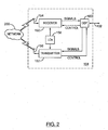
- Mobile device 100 comprises a number of components, the controlling component being microprocessor 102.
- Microprocessor 102 controls the overall operation of mobile device 100.
- Communication functions, including data and voice communications, are performed through communication subsystem 104.
- Communication subsystem 104 receives messages from and sends messages to a wireless network 200.
- communication subsystem 104 is configured in accordance with the Global System for Mobile Communication (GSM) and General Packet Radio Services (GPRS) standards.
- GSM Global System for Mobile Communication
- GPRS General Packet Radio Services
- the GSM/GPRS wireless network is used worldwide and it is expected that these standards will be superseded eventually by Enhanced Data GSM Environment (EDGE) and Universal Mobile Telecommunications Service (UMTS).
- EDGE Enhanced Data GSM Environment
- UMTS Universal Mobile Telecommunications Service
- the wireless link connecting communication subsystem 104 with network 200 represents one or more different Radio Frequency (RF) channels, operating according to defined protocols specified for GSM/GPRS communications. With newer network protocols, these channels are capable of supporting both circuit switched voice communications and packet switched data communications.
- RF Radio Frequency
- wireless network associated with mobile device 100 is a GSM/GPRS wireless network in one example implementation of mobile device 100
- other wireless networks may also be associated with mobile device 100 in variant implementations.
- Different types of wireless networks that may be employed include, for example, data-centric wireless networks, voice-centric wireless networks, and dual-mode networks that can support both voice and data communications over the same physical base stations.
- Combined dual-mode networks include, but are not limited to, Code Division Multiple Access (CDMA) or CDMA2000 networks, GSM/GPRS networks (as mentioned above), and future third-generation (3G) networks like EDGE and UMTS.
- CDMA Code Division Multiple Access
- GSM/GPRS networks as mentioned above
- 3G third-generation
- Some older examples of data-centric networks include the Mobitex TM Radio Network and the DataTAC TM Radio Network.
- Examples of older voice-centric data networks include Personal Communication Systems (PCS) networks like GSM and Time Division Multiple Access (TDMA) systems.
- PCS Personal Communication Systems
- TDMA Time Division Multiple
- Microprocessor 102 also interacts with additional subsystems such as a Random Access Memory (RAM) 106, flash memory 108, display 110, auxiliary input/output (I/O) subsystem 112, serial port 114, keyboard 116, speaker 118, microphone 120, short-range communications 122 and other devices 124.
- RAM Random Access Memory
- I/O auxiliary input/output subsystem 112
- serial port 114 serial port 114
- keyboard 116 keyboard 116
- speaker 118 microphone 120
- short-range communications 122 short-range communications 122 and other devices 124.
- Some of the subsystems of mobile device 100 perform communication-related functions, whereas other subsystems may provide "resident" or on-device functions.
- display 110 and keyboard 116 may be used for both communication-related functions, such as entering a text message for transmission over network 200, and device-resident functions such as a calculator or task list.
- Operating system software used by microprocessor 102 is typically stored in a persistent store such as flash memory 108, which may alternatively be a read-only memory (ROM) or similar storage element (not shown).
- ROM read-only memory
- RAM 106 volatile store
- Mobile device 100 may send and receive communication signals over network 200 after required network registration or activation procedures have been completed.
- Network access is associated with a subscriber or user of a mobile device 100.
- SIM Subscriber Identity Module
- SIM 126 is one type of a conventional "smart card” used to identify a subscriber of mobile device 100 and to personalize the mobile device 100, among other things. Without SIM 126, mobile device 100 is not fully operational for communication with network 200. By inserting SIM 126 into SIM interface 128, a subscriber can access all subscribed services.
- SIM 126 includes a processor and memory for storing information. Once SIM 126 is inserted in SIM interface 128, it is coupled to microprocessor 102. In order to identify the subscriber, SIM 126 contains some user parameters such as an International Mobile Subscriber Identity (IMSI).
- IMSI International Mobile Subscriber Identity
- An advantage of using SIM 126 is that a subscriber is not necessarily bound by any single physical mobile device. SIM 126 may store additional subscriber information for a mobile device as well, including datebook (or calendar) information and recent call information.
- Mobile device 100 is a battery-powered device and includes a battery interface 132 for receiving one or more rechargeable batteries 130.
- Battery interface 132 is coupled to a regulator (not shown), which assists battery 130 in providing power V+ to mobile device 100.
- a regulator not shown
- future technologies such as micro fuel cells may provide the power to mobile device 100.
- Microprocessor 102 in addition to its operating system functions, enables execution of software applications on mobile device 100.
- a set of applications that control basic device operations, including data and voice communication applications, will normally be installed on mobile device 100 during its manufacture.
- Another application that may be loaded onto mobile device 100 would be a personal information manager (PIM).
- PIM has functionality to organize and manage data items of interest to a subscriber, such as, but not limited to, e-mail, calendar events, voice mails, appointments, and task items.
- a PIM application has the ability to send and receive data items via wireless network 200.
- PIM data items may be seamlessly integrated, synchronized, and updated via wireless network 200 with the mobile device subscriber's corresponding data items stored and/or associated with a host computer system. This functionality creates a mirrored host computer on mobile device 100 with respect to such items. This can be particularly advantageous where the host computer system is the mobile device subscriber's office computer system.
- Additional applications may also be loaded onto mobile device 100 through network 200, auxiliary I/O subsystem 112, serial port 114, short-range communications subsystem 122, or any other suitable subsystem 124.
- This flexibility in application installation increases the functionality of mobile device 100 and may provide enhanced on-device functions, communication-related functions, or both.
- secure communication applications may enable electronic commerce functions and other such financial transactions to be performed using mobile device 100.
- Serial port 114 enables a subscriber to set preferences through an external device or software application and extends the capabilities of mobile device 100 by providing for information or software downloads to mobile device 100 other than through a wireless communication network.
- the alternate download path may, for example, be used to load an encryption key onto mobile device 100 through a direct and thus reliable and trusted connection to provide secure device communication.
- Short-range communications subsystem 122 provides for communication between mobile device 100 and different systems or devices, without the use of network 200.
- subsystem 122 may include an infrared device and associated circuits and components for short-range communication. Examples of short range communication would include standards developed by the Infrared Data Association (IrDA), Bluetooth, and the 802.11 family of standards developed by IEEE.
- IrDA Infrared Data Association
- Bluetooth Bluetooth
- 802.11 family of standards developed by IEEE IEEE
- a received signal such as a text message, an e-mail message, or web page download will be processed by communication subsystem 104 and input to microprocessor 102.
- Microprocessor 102 will then process the received signal for output to display 110 or alternatively to auxiliary I/O subsystem 112.
- a subscriber may also compose data items, such as e-mail messages, for example, using keyboard 116 in conjunction with display 110 and possibly auxiliary I/O subsystem 112.
- Auxiliary subsystem 112 may include devices such as: a touch screen, mouse, track ball, infrared fingerprint detector, or a roller wheel with dynamic button pressing capability.
- Keyboard 116 is an alphanumeric keyboard and/or telephone-type keypad.
- a composed item may be transmitted over network 200 through communication subsystem 104.
- mobile device 100 For voice communications, the overall operation of mobile device 100 is substantially similar, except that the received signals would be output to speaker 118, and signals for transmission would be generated by microphone 120.
- Alternative voice or audio I/O subsystems such as a voice message recording subsystem, may also be implemented on mobile device 100.
- voice or audio signal output is accomplished primarily through speaker 118, display 110 may also be used to provide additional information such as the identity of a calling party, duration of a voice call, or other voice call related information.
- Communication subsystem 104 comprises a receiver 150, a transmitter 152, one or more embedded or internal antenna elements 154, 156, Local Oscillators (LOs) 158, and a processing module such as a Digital Signal Processor (DSP) 160.
- DSP Digital Signal Processor
- communication subsystem 104 The particular design of communication subsystem 104 is dependent upon the network 200 in which mobile device 100 is intended to operate, thus it should be understood that the design illustrated in FIG. 2 serves only as one example.
- Signals received by antenna 154 through network 200 are input to receiver 150, which may perform such common receiver functions as signal amplification, frequency down conversion, filtering, channel selection, and analog-to-digital (A/D) conversion.
- A/D conversion of a received signal allows more complex communication functions such as demodulation and decoding to be performed in DSP 160.
- signals to be transmitted are processed, including modulation and encoding, by DSP 160.
- DSP-processed signals are input to transmitter 152 for digital-to-analog (D/A) conversion, frequency up conversion, filtering, amplification and transmission over network 200 via antenna 156.
- DSP 160 not only processes communication signals, but also provides for receiver and transmitter control. For example, the gains applied to communication signals in receiver 150 and transmitter 152 may be adaptively controlled through automatic gain control algorithms implemented in DSP 160.
- the wireless link between mobile device 100 and a network 200 may contain one or more different channels, typically different RF channels, and associated protocols used between mobile device 100 and network 200.
- a RF channel is a limited resource that must be conserved, typically due to limits in overall bandwidth and limited battery power of mobile device 100.
- transmitter 152 When mobile device 100 is fully operational, transmitter 152 is typically keyed or turned on only when it is sending to network 200 and is otherwise turned off to conserve resources. Similarly, receiver 150 is periodically turned off to conserve power until it is needed to receive signals or information (if at all) during designated time periods.
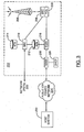
- network 200 comprises one or more nodes 202.
- Mobile device 100 communicates with a node 202 within wireless network 200.
- node 202 is configured in accordance with General Packet Radio Service (GPRS) and Global Systems for Mobile (GSM) technologies.
- GPRS General Packet Radio Service
- GSM Global Systems for Mobile
- Node 202 includes a base station controller (BSC) 204 with an associated tower station 206, a Packet Control Unit (PCU) 208 added for GPRS support in GSM, a Mobile Switching Center (MSC) 210, a Home Location Register (HLR) 212, a Visitor Location Registry (VLR) 214, a Serving GPRS Support Node (SGSN) 216, a Gateway GPRS Support Node (GGSN) 218, and a Dynamic Host Configuration Protocol (DHCP) 220.
- BSC base station controller
- PCU Packet Control Unit
- MSC Mobile Switching Center
- HLR Home Location Register
- VLR Visitor Location Registry
- SGSN Serving GPRS Support Node
- GGSN Gateway GPRS Support Node
- DHCP Dynamic Host Configuration Protocol
- MSC 210 is coupled to BSC 204 and to a landline network, such as a Public Switched Telephone Network (PSTN) 222 to satisfy circuit switched requirements.
- PSTN Public Switched Telephone Network
- the connection through PCU 208, SGSN 216 and GGSN 218 to the public or private network (Internet) 224 (also referred to herein generally as a shared network infrastructure) represents the data path for GPRS capable mobile devices.
- BSC 204 also contains a Packet Control Unit (PCU) 208 that connects to SGSN 216 to control segmentation, radio channel allocation and to satisfy packet switched requirements.
- PCU Packet Control Unit
- HLR 212 is shared between MSC 210 and SGSN 216. Access to VLR 214 is controlled by MSC 210.
- Station 206 is a fixed transceiver station. Station 206 and BSC 204 together form the fixed transceiver equipment.
- the fixed transceiver equipment provides wireless network coverage for a particular coverage area commonly referred to as a "cell".
- the fixed transceiver equipment transmits communication signals to and receives communication signals from mobile devices within its cell via station 206.
- the fixed transceiver equipment normally performs such functions as modulation and possibly encoding and/or encryption of signals to be transmitted to the mobile device in accordance with particular, usually predetermined, communication protocols and parameters, under control of its controller.
- the fixed transceiver equipment similarly demodulates and possibly decodes and decrypts, if necessary, any communication signals received from mobile device 100 within its cell. Communication protocols and parameters may vary between different nodes. For example, one node may employ a different modulation scheme and operate at different frequencies than other nodes.
- HLR 212 For all mobile devices 100 registered with a specific network, permanent configuration data such as a user profile is stored in HLR 212.
- HLR 212 also contains location information for each registered mobile device and can be queried to determine the current location of a mobile device.
- MSC 210 is responsible for a group of location areas and stores the data of the mobile devices currently in its area of responsibility in VLR 214.
- VLR 214 also contains information on mobile devices that are visiting other networks. The information in VLR 214 includes part of the permanent mobile device data transmitted from HLR 212 to VLR 214 for faster access. By moving additional information from a remote HLR 212 node to VLR 214, the amount of traffic between these nodes can be reduced so that voice and data services can be provided with faster response times and at the same time requiring less use of computing resources.
- SGSN 216 and GGSN 218 are elements added for GPRS support; namely packet switched data support, within GSM.
- SGSN 216 and MSC 210 have similar responsibilities within wireless network 200 by keeping track of the location of each mobile device 100.
- SGSN 216 also performs security functions and access control for data traffic on network 200.
- GGSN 218 provides internetworking connections with external packet switched networks and connects to one or more SGSNs 216 via an Internet Protocol (IP) backbone network operated within the network 200.
- IP Internet Protocol
- a given mobile device 100 must perform a "GPRS Attach" to acquire an IP address and to access data services. This requirement is not present in circuit switched voice channels as Integrated Services Digital Network (ISDN) addresses are used for routing incoming and outgoing calls.
- ISDN Integrated Services Digital Network
- GPRS capable networks use private, dynamically assigned IP addresses, thus requiring a DHCP server 220 connected to the GGSN 218.
- DHCP server 220 connected to the GGSN 218.
- RADIUS Remote Authentication Dial-In User Service
- a logical connection is established from a mobile device 100, through PCU 208, and SGSN 216 to an Access Point Node (APN) within GGSN 218.
- APN represents a logical end of an IP tunnel that can either access direct Internet compatible services or private network connections.
- the APN also represents a security mechanism for network 200, insofar as each mobile device 100 must be assigned to one or more APNs and mobile devices 100 cannot exchange data without first performing a GPRS Attach to an APN that it has been authorized to use.
- the APN may be considered to be similar to an Internet domain name such as "myconnection.wireless.com".
- IPsec IP Security
- VPN Virtual Private Networks
- PDP Packet Data Protocol
- network 200 will run an idle timer for each PDP Context to determine if there is a lack of activity.
- the PDP Context can be de-allocated and the IP address returned to the IP address pool managed by DHCP server 220.
- microprocessor 102 in addition to its operating system functions, enables execution of software applications on mobile device 100.
- a set of applications that control basic device operations, including data and voice communication applications, will normally be installed on mobile device 100 during its manufacture.
- Operating system software and other software applications are typically stored in a persistent store (e.g. flash memory 106) or other store, on mobile device 100 or on a device coupled thereto. It will be understood that the operating system, software applications or parts thereof, may be temporarily loaded in a volatile store such as RAM 106. Other instructions and/or data received by the mobile device 100 and subject to processing may also be temporarily stored in RAM 106.
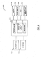
- Modules 310 interact with various components of mobile device 100. For instance, as shown by way of example in FIG. 4 , modules 310 may interact with communication subsystem 104, RAM 106, flash memory 108, display 110, auxiliary I/O device(s) 112, and keyboard 116. Modules 310 may comprise, for example, an address book module 312, a messaging module 314 (e.g. for e-mail and/or SMS or MMS messaging), and a phone application module 316.
- an address book module 312 e.g. for e-mail and/or SMS or MMS messaging
- Address book (also referred to as "contact book”) module 312 is generally configured to allow contact information (e.g. contact entries comprising individual contact and company names, telephone numbers, messaging addresses, pictures and other information) to be stored and managed.
- contact information e.g. contact entries comprising individual contact and company names, telephone numbers, messaging addresses, pictures and other information
- Messaging module 314 facilitates the sending and receiving of electronic messages over a wireless network 200 and/or other network.
- Phone application module 316 is generally configured to facilitate voice communication between the user and other parties, including the placement of outgoing calls by the user and the reception of incoming calls on the mobile device 100.
- Calls may be placed and received on a communication line specifically configured for voice communications.
- calls may alternatively or additionally be placed and received on other types of communication lines, including a communication line generally configured for data communications, or a communication line configured for both voice and data communications, for example.
- mobile device 100 may be configured to provide Voice over IP (VoIP) and/or video phone functionality.
- VoIP Voice over IP
- Some mobile devices are configured to provide access to multiple (i.e. two or more) communication lines on which incoming calls may be received. Typically, these mobile devices will also be configured to allow outgoing calls to be initiated by the user over the same communication lines. Each of the multiple communication lines may have a different telephone number associated therewith. For example, a user may have a business phone number and a different personal phone number.
- a line selection module e.g. alternate line service (ALS) module
- the line selection module 318 is configured to select a communication line to be used by phone application module 316, based upon line selection data stored on mobile device 100 (e.g. configuration settings that define a default communication line), and/or based upon input received by the user. It will be understood that the functionality of line selection module 318 may be provided or otherwise integrated with phone application module 316 or with a different module on mobile device 100.
- an incoming call screen is typically displayed, in which details of the call and a set of options for response are provided.
- details of the incoming call As users will likely want to consider details of the incoming call first in order to determine the user's course of action (e.g. whether to answer the call or not), it may be desirable to provide more detailed information on the incoming call to a user at the time the call is first received.
- the amount of such caller identification information that may be provided to users is often restricted in known user interfaces, as a substantial portion of the incoming call screen is typically also used to provide details on all the available options for response at the time the call is first received, and the amount of screen area provided by a mobile device is generally limited.
- Embodiments described herein are generally directed to a system and method for providing an improved user interface for receiving calls on phone-equipped mobile devices.
- embodiments described herein relate generally to a user interface that provides an incoming call screen to the user, where the incoming call screen comprises a caller identification data field for displaying data associated with incoming calls and at least one key label field in which labels for mobile device keys (e.g. send and end keys) are displayed.
- the incoming call screen comprises a caller identification data field for displaying data associated with incoming calls and at least one key label field in which labels for mobile device keys (e.g. send and end keys) are displayed.
- the combined areas of the caller identification data field and the at least one key label field substantially occupies the entire visible area of the display of the mobile device.
- the area of the caller identification data field is substantially greater than the area of the at least one key label field, enabling more information pertaining to incoming calls to be displayed to the user when a call is first received at the mobile device.
- this is facilitated by providing user-selectable options for responding to incoming calls in an options menu, which can be accessed by a user but is not initially displayed to the user when an incoming call is first received.
- the options menu is displayed on the incoming call screen only if a direction to display the options menu is received from the user after the incoming call is first received at the mobile device.
- the options menu is accessible when the user depresses a menu key or other pre-programmed key on the mobile device after the incoming call is first received at the mobile device.
- An options menu identifier e.g. "More”
- labels e.g. phone icons, text identifiers
- hints to indicate the function of these keys.
- Each of these labels is displayed in a key label field on the display (e.g. near the respective key, or with an additional identifier that otherwise indicates the respective key). Accordingly, virtual buttons to identify the same actions associated with these keys need not be displayed in the caller identification data field when a call is first received at the mobile device.
- a wireless audio device icon is displayed with the label for the send key to indicate that audio signals for the call will be transmitted to an auxiliary audio device rather than to an integrated speaker on the mobile device.
- the auxiliary audio device may be, for example, a wireless audio device (e.g. a Bluetooth TM headset or earpiece, a remote speaker).
- At least some caller identification data is displayed in an area of the caller identification data field that is substantially centered along at least one axis of the display.
- certain caller identification data e.g. name of caller, phone number, picture, and/or company name
- caller identification data displayed in the caller identification data field comprises data (e.g. company name, picture) from a contact entry associated with an incoming call on the mobile device.
- caller identification data displayed in the caller identification data field comprises data identifying the communication line on which a call is received at the mobile device.
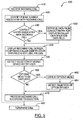
- FIG. 5 a flowchart illustrating steps of a method of providing a user interface for managing calls received at a mobile device in accordance with at least one embodiment is shown generally as 400. Additional details of some of the features described below in respect of the steps of method 400 may be described earlier in the present specification.
- the steps of method 400 are performed at the mobile device by an application (e.g. phone application module 316 of FIG. 4 ) that executes and resides on the mobile device (e.g. mobile device 100 of FIG. 1 ).
- the application need not be a stand-alone application, and the functionality described herein may be implemented in one or more applications executing and residing on the mobile device.
- a call for a user of the mobile device (“incoming call") is received on a communication line accessible at the mobile device.
- the call may be received over a communication line specifically configured for voice communications, for data communications, or for both, depending on the implementation.
- the phone number associated with the incoming call is identified.
- the phone number may subsequently be displayed to the user (e.g. at step 440). It may also be used, for example, to determine the identity of the caller and to associate the incoming call with a contact entry in the user's address book (e.g. at steps 430 and 432).
- further data items from the associated contact entry e.g. individual name, company name, picture
- an incoming call screen is displayed to the user on a display (e.g. display 110 of FIG. 1 ) of the mobile device.
- the incoming call screen informs the user that a call is being received at the mobile device, and presents the user with options for response.
- the incoming call screen is divided into a caller identification data field for displaying data associated with the incoming call, and at least one key label field in which labels can be displayed to inform the user of at least some actions that may be taken by the user by depressing certain keys provided on the mobile device. Further user interface features in respect of the incoming call screen that may be implemented in various embodiments are illustrated with reference to the example screenshots of FIGS. 6 through 8 .
- the user when a call is first received at the mobile device, the user will typically look at the displayed incoming call screen to see who is calling. Accordingly, it may be preferable to have a substantial portion of the incoming call screen dedicated to providing the information that identifies the caller when the call is first received. The user will then need to decide what action should be taken with respect to the incoming call. It is expected that the user will often decide to simply answer or ignore the call by depressing the send or the end key without the need to consider alternative response options.
- a comprehensive list of available options is not provided on the incoming call screen when a call is first received.
- the area of the at least one key label field can be kept relatively small (e.g. occupying about 10% of the display). This may allow, for example, a greater number of caller identification data items to be displayed, and/or greater flexibility in laying out caller identification data items within the caller identification data field so that they might be more easily read by the user.
- a selection of a mobile device key made by the user is detected.
- the selected key may be a send key (e.g. an "Answer” key), an end key (e.g. an "Ignore” key), a menu key, or some other pre-programmed key.
- step 460 it is determined whether the selection made at step 450 is to result in the display of an options menu. For example, if a menu key is pressed, an options menu will be displayed to the user.
- the user directs that an option menu be displayed when the user wishes to consider additional options for responding to the incoming call (e.g. "advanced options") other than the basic answer and ignore functions available by pressing the send or end keys.
- additional options e.g. "advanced options”
- the information identifying the caller as displayed in the caller identification data field need not be obscured unless the user specifically wishes to consider the additional options.
- the menu key may or may not be identified by an options menu identifier displayed in association with that menu key. Where the menu key is to be identified by an options menu identifier, the options menu identifier is displayed in a key label field in this embodiment.
- An options menu provides the user with options for responding to the call currently being received at the mobile device. For example, where the user is already engaged in a different call when the incoming call is received, the user may be provided with the following options: answer the incoming call and hold the other call, answer the incoming call and drop the other call, or ignore the incoming call and continue with the other call.
- an option may be provided to place the incoming call on hold, until the user makes a further selection to answer or drop the call.
- an option may be provided to forward the incoming call to another telephone number (e.g. a landline telephone).
- an option may be provided to redirect audio output to a specified device (e.g. a wireless headset, a remote speaker).
- step 460 If it is determined at step 460 that the selection requires an option menu to be displayed, the option menu is displayed at step 462, and a selection of an option by the user is detected at step 464. Otherwise, the flow of method steps proceeds directly to step 470.
- the incoming call is processed according to the selection of the mobile device key by the user as detected at step 450, or the selection of an option from the options menu by the user as detected at step 464, depending on the determination made at step 460.
- the incoming call may be answered or ignored at this step, in known manner. If the incoming call has been received while the user is engaged in a different call, the different call may be put on hold or dropped at this step for example, in known manner.
- the call will continue until it is terminated (e.g. by the user or by the caller) at step 480.
- a further call may be received at the mobile device while the user is already engaged in a call if, for example, the mobile device is configured to provide "call waiting" functionality.
- a further iteration of method 400 may be performed before the previous iteration has terminated. In that case, the steps of a new instance of method 400 may be concurrently performed as shown by the dotted arrow in FIG. 5 .
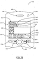
- FIG. 6 a screenshot of a user interface provided to a user in accordance with an example implementation of one embodiment is shown generally as 500.
- screenshot 500 illustrates a user interface displayed in a display 110 of a mobile device 100, namely for an incoming call screen 510 used to inform the user of calls being received at mobile device 100.
- Mobile device 100 provides an integrated speaker 118, a visual alert indicator 512, a send key 514, an end key 516 (end key 516 is also used as a power-on key in this example implementation), a track ball 518, a menu key 520, and an escape key 522.
- send key 514, end key 516, menu key 520 and escape key 522 are shown as physical keys provided on the mobile device in this example, it will be understood by persons skilled in the art that some mobile devices may provide one or more of these keys as virtual keys on a touch-sensitive screen.
- Incoming call screen 510 is divided into a caller identification data field 530 and a key label field 532.
- the combined areas of caller identification data field 530 and key label field 532 occupy the entire area of display 110.
- the area of caller identification data field 530 is much greater than the area of key label field 532, allowing for greater flexibility in the layout of caller identification data and potentially making displayed caller identification data easier to read.
- key label field 532 is illustrated as one contiguous field, although more than one separate key label field may be displayed on incoming call screen 510 in variant embodiments.
- caller identification data field 530 the following items are displayed in caller identification data field 530:
- key label field 532 is confined to a narrow section of display 110, at an end of display 110 nearest the send key 514 and end key 516 provided by mobile device 100.
- a first label is displayed in an area on display 110 within key label field 532 close to and above send key 514.
- the first label comprises a text identifier "Answer” 550 and an answer icon 552.
- a Bluetooth TM headset has been activated for use, and accordingly, a wireless audio device icon (e.g. a Bluetooth TM symbol) 554 is also shown with the first label.
- a second label is displayed in an area on display 110 within key label field 532 close to and above end key 516.
- the second label comprises a text identifier "Ignore" 556 and an ignore icon 558.
- An options menu identifier 560 is also displayed within key label field 532.
- options menu identifier 560 is displayed in an area close to and above track ball 518, and includes a white circle to suggest that the track ball 518 can be depressed to direct that an options menu be displayed.
- a direction to display to the options menu may be provided by depressing a different key (e.g. menu key 520) depending on the implementation.
- the options menu may also be displayed after a user depresses a key such as the menu key 520 even if an options menu identifier 560 has not been displayed within key label field 532.
- FIG. 7A a screenshot of a user interface provided to a user in accordance with an example implementation of another embodiment is shown generally as 600.
- Screenshot 600 illustrates a number of similar elements as shown in FIG. 6 . Similar reference numerals are used to refer to similar elements, and reference may be made to the description in respect of screenshot 500 of FIG. 6 for further details on those elements that also appear in screenshot 600.
- an "incoming call" indicator 602 is displayed, shown centrally justified (horizontally) near the top of display 110 in this example, indicating that a call is being received at mobile device 100.
- options menu identifier 560 FIG. 6
- an option menu may still be accessible (e.g. by pressing menu key 520) even if options menu identifier 560 is not shown. It will also be understood that an options menu identifier may be shown even if the user is not currently engaged in a different call.
- a company name 604, along with name of the caller 544, phone number 546, and picture 548 is displayed in caller identification data field 530.
- a contact entry associated with the incoming call is determined by matching phone number 546 to a corresponding data item in a contact entry stored on the mobile device.
- data items in the contact entry such as name of the caller 544, picture 548, and/or company name 604 can be retrieved for display on the caller identification data field 530 of incoming call screen 510.
- FIG. 7B showing a screenshot 610 in display 110, where the user has directed the associated contact entry 612 to be displayed.
- FIG. 7B is an example of a screenshot of a user interface that displays contact entry data used to populate the user interface of FIG. 7A .
- Contact entry 612 comprises a contact name 544, a company name 604, and a title 614 within a primary contact details field 616. Contact entry 612 further comprises one or more pictures 548 associated with the contact. Contact entry 612 further comprises an e-mail address 618, and a second "Work" phone number 620 in addition to "Home" phone number 546, within one or more contact details fields 622. Although not shown in FIG. 7A , an identification of the caller's line (e.g. "Work", "Home”) can also be determined for display in caller identification data field 530.
- contact details field 622 Further phone numbers or other contact details may be provided within contact details field 622. The existence of additional contact details is indicated in this example by icon 624.
- a phone number for an incoming call when a phone number for an incoming call is identified, it can be matched to a phone number in the contact details field 622 of contact entries stored on mobile device 100 to determine the associated contact entry (if one exists). Data from the associated contact entry can then be retrieved for display.
- FIG. 8 a screenshot of a user interface provided to a user in accordance with an example implementation of another embodiment is shown generally as 700.
- Screenshot 700 illustrates a number of similar elements as shown in FIGS. 6 , 7A and 7B . Similar reference numerals are used to refer to similar elements, and reference may be made to the description in respect of the corresponding screenshots of FIGS. 6 , 7A and 7B for further details on those elements that also appear in screenshot 700.
- mobile device 100 provides access to multiple communication lines.
- Communication line identifier 702 is displayed to indicate that the incoming call is being received on the user's "Business" line.
- the "waiting call” indicator 542 also indicates that a call is being received while the user is already engaged in a different call.
- an options menu 704 is displayed. Options menu 704 may be displayed in response to the user pressing menu key 520 or track ball 518 for example, prompting the user for further direction on how to handle the incoming call and the other call that the user is engaged in.
- options menu 704 the user is provided with a first option 706 to answer the incoming call and hold the other call, a second option 708 to answer the incoming call and drop the other call, and a third option 710 to ignore the incoming call and continue with the other call.
- An answer icon 552 and ignore icon 558 can also be displayed in association with the options provided in options menu 704 to suggest that the user can also select the corresponding option 706 or 710 by pressing send key 514 or end key 516 respectively. Other options not shown in this example may be provided in options menu 704.
- the steps of a method of providing a user interface for managing calls received at a mobile device in accordance with any of the embodiments described herein may be provided as executable software instructions stored on computer-readable media, which may include transmission-type media.
Claims (17)
- Procédé de fourniture d'une interface utilisateur pour gérer des appels reçus au niveau d'un dispositif mobile (100), le dispositif mobile (100) fournissant l'accès à au moins une première ligne de communication configurée pour recevoir les appels, le dispositif mobile (100) fournissant des touches d'envoi et de fin (514, 516), le procédé comprenant les étapes consistant à :identifier (420) un numéro de téléphone associé à un appel entrant qui est reçu au niveau du dispositif mobile (100) ; etafficher (440) un écran d'appel entrant (510) sur un afficheur (110) du dispositif mobile (100), l'écran d'appel entrant (510) comprenant un champ de données d'identification d'appelant (530) pour afficher des données associées à des appels entrants, et au moins un champ d'étiquette de touche (532) dans lequel des première et deuxième étiquettes pour la touche d'envoi (514) et la touche de fin (516) respectivement sont affichées adjacentes à la touche d'envoi (514) et la touche de fin (516) respectivement, la touche d'envoi (514) étant sélectionnable pour répondre à l'appel entrant et la touche de fin (516) étant sélectionnable pour ignorer l'appel entrant ;dans lequel la surface du champ de données d'identification d'appelant (530) est plus grande que la surface de l'au moins un champ d'étiquette de touche (532) ; etdans lequel un menu d'options (704) est affiché sur l'écran d'appel entrant (510) comprenant des options sélectionnables par l'utilisateur pour répondre à l'appel entrant si une instruction pour afficher le menu d'options (704) est reçue après que l'appel entrant est d'abord reçu au niveau du dispositif mobile (100) ; etdans lequel une troisième étiquette est affichée dans l'au moins un champ d'étiquette de touche (532) à l'affichage (440) si l'appel entrant est reçu au niveau du dispositif mobile alors que le dispositif mobile (100) est engagé dans un appel différent mais la troisième étiquette n'est pas affichée à l'affichage (440) si l'appel entrant est reçu au niveau du dispositif mobile (100) alors que le dispositif mobile n'est pas engagé dans un appel différent, la troisième étiquette comprenant un identificateur de menu d'options (560) associé au menu d'options (704).
- Procédé selon la revendication 1, dans lequel la surface du champ de données d'identification d'appelant (530) et la surface de l'au moins un champ d'étiquette de touche (532), en combinaison, occupent la surface visible entière sur l'afficheur (110) du dispositif mobile (100).
- Procédé selon la revendication 1 ou la revendication 2, dans lequel l'au moins un champ d'étiquette de touche (532) occupe environ 10% de la surface de l'afficheur (110).
- Procédé selon l'une quelconque des revendications précédentes, dans lequel à l'étape d'affichage (440), l'au moins un champ d'étiquette de touche (532) est affiché à proximité des touches d'envoi et de fin (514, 516), de sorte que la première étiquette soit affichée dans une zone de l'afficheur (110) adjacente à la touche d'envoi (514), et que la deuxième étiquette soit affichée dans une zone de l'afficheur (110) adjacente à la touche de fin (516).
- Procédé selon l'une quelconque des revendications précédentes, dans lequel la première étiquette comprend une icône répondre (552) et un identificateur de texte correspondant (550), et dans lequel la deuxième étiquette comprend une icône ignorer (558) et un identificateur de texte correspondant (556).
- Procédé selon l'une quelconque des revendications précédentes, dans lequel la première étiquette comprend une icône de dispositif audio sans fil (554).
- Procédé selon l'une quelconque des revendications précédentes, comprenant en outre les étapes consistant à :détecter (450) quand l'une des touches d'envoi et de fin (514, 516) est sélectionnée, et traiter (470) l'appel entrant conformément à la touche sélectionnée (514, 516).
- Procédé selon l'une quelconque des revendications précédentes, dans lequel la troisième étiquette est affichée dans l'au moins un champ d'étiquette de touche (532) près et au-dessus d'une boule de commande (518).
- Procédé selon l'une quelconque des revendications précédentes, comprenant en outre les étapes consistant à :détecter (460) quand l'instruction pour afficher le menu d'options (704) est fournie, afficher (462) le menu d'options (704), détecter (464) quand une option (706, 708, 710) est sélectionnée à partir du menu d'options (704), et traiter l'appel entrant conformément à l'option sélectionnée (706, 708, 710).
- Procédé selon l'une quelconque des revendications précédentes, dans lequel au moins un élément de données associé à l'appel entrant est affiché dans une zone du champ de données d'identification d'appelant (530) qui est centrée verticalement et/ou horizontalement dans l'afficheur (110) .
- Procédé selon l'une quelconque des revendications précédentes, comprenant en outre les étapes consistant à :déterminer (430) une entrée de contact (612) associée à l'appel entrant sur le dispositif mobile (100) en mettant en correspondance le numéro de téléphone associé à l'appel entrant avec un élément de données dans l'entrée de contact (612), et afficher (440) au moins un élément de l'entrée de contact dans le champ de données d'identification d'appelant.
- Procédé selon la revendication 11, dans lequel l'au moins un élément de l'entrée de contact (612) affiché dans le champ de données d'identification d'appelant (530) comprend un nom d'entreprise (604).
- Procédé selon la revendication 11, dans lequel l'entrée de contact (612) associée à l'appel entrant est stockée dans un carnet d'adresses sur le dispositif mobile (100).
- Procédé selon l'une quelconque des revendications précédentes, dans lequel le dispositif mobile (100) fournit l'accès à une pluralité de lignes de communication configurées pour recevoir des appels, et dans lequel des données identifiant la ligne de communication sur laquelle l'appel entrant est reçu (702) sont affichées dans le champ de données d'identification d'appelant à l'étape d'affichage (440).
- Support lisible par ordinateur comprenant des instructions exécutables sur un processeur (102) d'un dispositif mobile (100) pour mettre en oeuvre les étapes du procédé selon l'une quelconque des revendications précédentes.
- Système destiné à fournir une interface utilisateur pour gérer des appels reçus au niveau d'un dispositif mobile (100), le dispositif mobile (100) fournissant l'accès à au moins une première ligne de communication configurée pour recevoir des appels, le dispositif mobile (100) fournissant des touches d'envoi et de fin (514, 516), le dispositif mobile (100) comprenant un processeur (102), un afficheur (110) et au moins un dispositif d'entrée (112, 116, 518), le système étant configuré pour exécuter une application programmée pour effectuer les étapes du procédé tel que revendiqué dans l'une quelconque des revendications 1 à 14.
- Dispositif mobile (100) sur lequel une interface utilisateur pour gérer des appels reçus au niveau du dispositif mobile (100) est fournie, le dispositif mobile (100) fournissant l'accès à au moins une première ligne de communication configurée pour recevoir les appels, le dispositif mobile (100) fournissant des touches d'envoi et de fin (514, 516), le dispositif mobile (100) comprenant un processeur (102), un afficheur (110) et au moins un dispositif d'entrée (112, 116, 518), le dispositif mobile (100) étant configuré pour effectuer les étapes du procédé tel que revendiqué dans l'une quelconque des revendications 1 à 14.
Priority Applications (3)
| Application Number | Priority Date | Filing Date | Title |
|---|---|---|---|
| EP07104940.7A EP1976244B1 (fr) | 2007-03-26 | 2007-03-26 | Système et procédé pour fournir une interface utilisateur pour gérer les appels reçus sur un dispositif mobile |
| EP12175547.4A EP2512109B1 (fr) | 2007-03-26 | 2007-03-26 | Procédé et dispositif mobile pour fournir une interface utilisateur pour gérer les appels reçus. |
| CA2625550A CA2625550C (fr) | 2007-03-26 | 2008-03-14 | Systeme et methode permettant d'obtenir une interface-utilisateur de gestion des appels recus a un dispositif mobile |
Applications Claiming Priority (1)
| Application Number | Priority Date | Filing Date | Title |
|---|---|---|---|
| EP07104940.7A EP1976244B1 (fr) | 2007-03-26 | 2007-03-26 | Système et procédé pour fournir une interface utilisateur pour gérer les appels reçus sur un dispositif mobile |
Related Child Applications (2)
| Application Number | Title | Priority Date | Filing Date |
|---|---|---|---|
| EP12175547.4A Division-Into EP2512109B1 (fr) | 2007-03-26 | 2007-03-26 | Procédé et dispositif mobile pour fournir une interface utilisateur pour gérer les appels reçus. |
| EP12175547.4A Division EP2512109B1 (fr) | 2007-03-26 | 2007-03-26 | Procédé et dispositif mobile pour fournir une interface utilisateur pour gérer les appels reçus. |
Publications (2)
| Publication Number | Publication Date |
|---|---|
| EP1976244A1 EP1976244A1 (fr) | 2008-10-01 |
| EP1976244B1 true EP1976244B1 (fr) | 2014-04-23 |
Family
ID=38510322
Family Applications (2)
| Application Number | Title | Priority Date | Filing Date |
|---|---|---|---|
| EP07104940.7A Active EP1976244B1 (fr) | 2007-03-26 | 2007-03-26 | Système et procédé pour fournir une interface utilisateur pour gérer les appels reçus sur un dispositif mobile |
| EP12175547.4A Active EP2512109B1 (fr) | 2007-03-26 | 2007-03-26 | Procédé et dispositif mobile pour fournir une interface utilisateur pour gérer les appels reçus. |
Family Applications After (1)
| Application Number | Title | Priority Date | Filing Date |
|---|---|---|---|
| EP12175547.4A Active EP2512109B1 (fr) | 2007-03-26 | 2007-03-26 | Procédé et dispositif mobile pour fournir une interface utilisateur pour gérer les appels reçus. |
Country Status (2)
| Country | Link |
|---|---|
| EP (2) | EP1976244B1 (fr) |
| CA (1) | CA2625550C (fr) |
Families Citing this family (10)
| Publication number | Priority date | Publication date | Assignee | Title |
|---|---|---|---|---|
| US8463325B2 (en) | 2007-03-26 | 2013-06-11 | Research In Motion Limited | System and method for providing calling feature icons in a user interface that facilitates user selection of a communication line for an outgoing call on a mobile device |
| US8478345B2 (en) | 2007-03-26 | 2013-07-02 | Research In Motion Limited | System and method for providing a user interface that facilitates user selection of a communication line for an outgoing call on a mobile device |
| US9270800B2 (en) | 2008-03-04 | 2016-02-23 | Blackberry Limited | Systems and methods for providing alternate line selection information on a mobile device |
| US20090279679A1 (en) * | 2008-05-12 | 2009-11-12 | Research In Motion Limited | Line indication |
| DE102008029847A1 (de) * | 2008-06-25 | 2009-12-31 | Deutsche Telekom Ag | Mobiltelefon |
| US9841293B2 (en) | 2010-01-26 | 2017-12-12 | Calrion Co., Ltd. | In-vehicle display system for navigation and additional functions |
| EP2747392B1 (fr) * | 2012-12-18 | 2017-08-23 | Acer Incorporated | Appareil électronique portable et son procédé de traitement d'appels entrants |
| TWI566568B (zh) * | 2012-12-18 | 2017-01-11 | 宏碁股份有限公司 | 手持式電子裝置及其來電通話處理方法 |
| US9225850B2 (en) | 2012-12-18 | 2015-12-29 | Acer Incorporated | Handheld electronic apparatus and incoming call processing method thereof |
| JP6364035B2 (ja) * | 2016-01-29 | 2018-07-25 | 京セラ株式会社 | 携帯電話、表示制御方法、およびプログラム |
Family Cites Families (10)
| Publication number | Priority date | Publication date | Assignee | Title |
|---|---|---|---|---|
| TW226510B (en) | 1993-01-19 | 1994-07-11 | Novatel Comm Ltd | Wireline interface for cellular telephone |
| MY118477A (en) | 1994-04-20 | 2004-11-30 | Sony Corp | Communication terminal apparatus and control method thereof |
| FI961277A (fi) | 1996-03-20 | 1997-09-21 | Nokia Mobile Phones Ltd | Menetelmä merkkijonon muodostamiseksi, elektroninen viestinlaite sekä latausyksikkö elektronisen viestinlaitteen lataamiseksi |
| US8064886B2 (en) | 1999-08-12 | 2011-11-22 | Hewlett-Packard Development Company, L.P. | Control mechanisms for mobile devices |
| KR100383610B1 (ko) | 2001-06-04 | 2003-05-14 | 삼성전자주식회사 | 셀룰러 전화기의 호 서비스 방법 |
| US7046994B1 (en) | 2002-02-01 | 2006-05-16 | Microsoft Corporation | System and method for associating a contact with a call ID |
| EP1434411A1 (fr) * | 2002-12-23 | 2004-06-30 | Sony Ericsson Mobile Communications AB | Appareil portable fournissant des informations détaillées sur les icones d'état |
| CN1765065B (zh) * | 2003-04-17 | 2010-12-01 | 富士通株式会社 | 具有天线切换功能的信息处理装置 |
| US20050020316A1 (en) * | 2003-07-25 | 2005-01-27 | Hassan Mahini | Event list menu for accessing menu items in a hierarchical menu |
| WO2006067541A1 (fr) | 2004-12-22 | 2006-06-29 | Nokia Corporation | Interface de telephone mobile s'utilisant dans un vehicule |
-
2007
- 2007-03-26 EP EP07104940.7A patent/EP1976244B1/fr active Active
- 2007-03-26 EP EP12175547.4A patent/EP2512109B1/fr active Active
-
2008
- 2008-03-14 CA CA2625550A patent/CA2625550C/fr active Active
Also Published As
| Publication number | Publication date |
|---|---|
| EP2512109B1 (fr) | 2015-11-18 |
| CA2625550C (fr) | 2013-06-25 |
| EP1976244A1 (fr) | 2008-10-01 |
| CA2625550A1 (fr) | 2008-09-26 |
| EP2512109A1 (fr) | 2012-10-17 |
Similar Documents
| Publication | Publication Date | Title |
|---|---|---|
| US7860489B2 (en) | System and method for providing a user interface for managing calls received at a mobile device | |
| EP1976244B1 (fr) | Système et procédé pour fournir une interface utilisateur pour gérer les appels reçus sur un dispositif mobile | |
| US8081992B2 (en) | System and method for displaying the geographic location associated with a phone call received on a phone-equipped mobile device | |
| US8744531B2 (en) | System and method for providing calling feature icons in a user interface that facilitates user selection of a communication line for an outgoing call on a mobile device | |
| US9876898B2 (en) | Systems and methods for providing alternate line selection information on a mobile device | |
| US8478345B2 (en) | System and method for providing a user interface that facilitates user selection of a communication line for an outgoing call on a mobile device | |
| CA2624043C (fr) | Systeme et methode permettant d'obtenir des icones de fonction d'appel dans une interface-utilisateur, ce qui facilite la selection de l'utilisateur d'une ligne de communication pour un appel sortant de dispositif mobile | |
| CA2624042C (fr) | Systeme et methode permettant d'obtenir une interface-utilisateur, ce qui facilite la selection de l'utilisateur d'une ligne de communication pour un appel sortant de dispositif mobile | |
| CA2657496C (fr) | Systemes et methodes permettant d'obtenir des informations substitutives portant sur la selection possible sur un appareil de communication mobile | |
| US8260293B2 (en) | Devices and methods for placing a call on a selected communication line | |
| US8126508B2 (en) | Systems and methods for selecting a calling card to be used in placing an outgoing call | |
| EP2317738B1 (fr) | Dispositifs et procédés pour effectuer un appel sur une ligne de communication choisie | |
| EP2216967B1 (fr) | Systèmes et procédés pour sélectionner une carte d'appel à utiliser lors d'un appel sortant |
Legal Events
| Date | Code | Title | Description |
|---|---|---|---|
| PUAI | Public reference made under article 153(3) epc to a published international application that has entered the european phase |
Free format text: ORIGINAL CODE: 0009012 |
|
| 17P | Request for examination filed |
Effective date: 20070326 |
|
| AK | Designated contracting states |
Kind code of ref document: A1 Designated state(s): AT BE BG CH CY CZ DE DK EE ES FI FR GB GR HU IE IS IT LI LT LU LV MC MT NL PL PT RO SE SI SK TR |
|
| AX | Request for extension of the european patent |
Extension state: AL BA HR MK RS |
|
| AKX | Designation fees paid |
Designated state(s): AT BE BG CH CY CZ DE DK EE ES FI FR GB GR HU IE IS IT LI LT LU LV MC MT NL PL PT RO SE SI SK TR |
|
| AXX | Extension fees paid |
Extension state: RS Payment date: 20070326 Extension state: HR Payment date: 20070326 Extension state: MK Payment date: 20070326 Extension state: BA Payment date: 20070326 Extension state: AL Payment date: 20070326 |
|
| 17Q | First examination report despatched |
Effective date: 20100709 |
|
| RAP1 | Party data changed (applicant data changed or rights of an application transferred) |
Owner name: BLACKBERRY LIMITED |
|
| GRAP | Despatch of communication of intention to grant a patent |
Free format text: ORIGINAL CODE: EPIDOSNIGR1 |
|
| INTG | Intention to grant announced |
Effective date: 20131025 |
|
| RAP1 | Party data changed (applicant data changed or rights of an application transferred) |
Owner name: BLACKBERRY LIMITED |
|
| GRAS | Grant fee paid |
Free format text: ORIGINAL CODE: EPIDOSNIGR3 |
|
| GRAA | (expected) grant |
Free format text: ORIGINAL CODE: 0009210 |
|
| AK | Designated contracting states |
Kind code of ref document: B1 Designated state(s): AT BE BG CH CY CZ DE DK EE ES FI FR GB GR HU IE IS IT LI LT LU LV MC MT NL PL PT RO SE SI SK TR |
|
| AX | Request for extension of the european patent |
Extension state: AL BA HR MK RS |
|
| REG | Reference to a national code |
Ref country code: GB Ref legal event code: FG4D |
|
| REG | Reference to a national code |
Ref country code: CH Ref legal event code: EP |
|
| REG | Reference to a national code |
Ref country code: AT Ref legal event code: REF Ref document number: 664398 Country of ref document: AT Kind code of ref document: T Effective date: 20140515 |
|
| REG | Reference to a national code |
Ref country code: IE Ref legal event code: FG4D |
|
| REG | Reference to a national code |
Ref country code: DE Ref legal event code: R096 Ref document number: 602007036206 Country of ref document: DE Effective date: 20140605 |
|
| REG | Reference to a national code |
Ref country code: NL Ref legal event code: T3 |
|
| REG | Reference to a national code |
Ref country code: AT Ref legal event code: MK05 Ref document number: 664398 Country of ref document: AT Kind code of ref document: T Effective date: 20140423 |
|
| REG | Reference to a national code |
Ref country code: LT Ref legal event code: MG4D |
|
| PG25 | Lapsed in a contracting state [announced via postgrant information from national office to epo] |
Ref country code: FI Free format text: LAPSE BECAUSE OF FAILURE TO SUBMIT A TRANSLATION OF THE DESCRIPTION OR TO PAY THE FEE WITHIN THE PRESCRIBED TIME-LIMIT Effective date: 20140423 Ref country code: IS Free format text: LAPSE BECAUSE OF FAILURE TO SUBMIT A TRANSLATION OF THE DESCRIPTION OR TO PAY THE FEE WITHIN THE PRESCRIBED TIME-LIMIT Effective date: 20140823 Ref country code: BG Free format text: LAPSE BECAUSE OF FAILURE TO SUBMIT A TRANSLATION OF THE DESCRIPTION OR TO PAY THE FEE WITHIN THE PRESCRIBED TIME-LIMIT Effective date: 20140723 Ref country code: GR Free format text: LAPSE BECAUSE OF FAILURE TO SUBMIT A TRANSLATION OF THE DESCRIPTION OR TO PAY THE FEE WITHIN THE PRESCRIBED TIME-LIMIT Effective date: 20140724 Ref country code: LT Free format text: LAPSE BECAUSE OF FAILURE TO SUBMIT A TRANSLATION OF THE DESCRIPTION OR TO PAY THE FEE WITHIN THE PRESCRIBED TIME-LIMIT Effective date: 20140423 Ref country code: CY Free format text: LAPSE BECAUSE OF FAILURE TO SUBMIT A TRANSLATION OF THE DESCRIPTION OR TO PAY THE FEE WITHIN THE PRESCRIBED TIME-LIMIT Effective date: 20140423 |
|
| PG25 | Lapsed in a contracting state [announced via postgrant information from national office to epo] |
Ref country code: PL Free format text: LAPSE BECAUSE OF FAILURE TO SUBMIT A TRANSLATION OF THE DESCRIPTION OR TO PAY THE FEE WITHIN THE PRESCRIBED TIME-LIMIT Effective date: 20140423 Ref country code: LV Free format text: LAPSE BECAUSE OF FAILURE TO SUBMIT A TRANSLATION OF THE DESCRIPTION OR TO PAY THE FEE WITHIN THE PRESCRIBED TIME-LIMIT Effective date: 20140423 Ref country code: SE Free format text: LAPSE BECAUSE OF FAILURE TO SUBMIT A TRANSLATION OF THE DESCRIPTION OR TO PAY THE FEE WITHIN THE PRESCRIBED TIME-LIMIT Effective date: 20140423 Ref country code: AT Free format text: LAPSE BECAUSE OF FAILURE TO SUBMIT A TRANSLATION OF THE DESCRIPTION OR TO PAY THE FEE WITHIN THE PRESCRIBED TIME-LIMIT Effective date: 20140423 Ref country code: ES Free format text: LAPSE BECAUSE OF FAILURE TO SUBMIT A TRANSLATION OF THE DESCRIPTION OR TO PAY THE FEE WITHIN THE PRESCRIBED TIME-LIMIT Effective date: 20140423 |
|
| PG25 | Lapsed in a contracting state [announced via postgrant information from national office to epo] |
Ref country code: PT Free format text: LAPSE BECAUSE OF FAILURE TO SUBMIT A TRANSLATION OF THE DESCRIPTION OR TO PAY THE FEE WITHIN THE PRESCRIBED TIME-LIMIT Effective date: 20140825 |
|
| REG | Reference to a national code |
Ref country code: DE Ref legal event code: R097 Ref document number: 602007036206 Country of ref document: DE |
|
| PG25 | Lapsed in a contracting state [announced via postgrant information from national office to epo] |
Ref country code: RO Free format text: LAPSE BECAUSE OF FAILURE TO SUBMIT A TRANSLATION OF THE DESCRIPTION OR TO PAY THE FEE WITHIN THE PRESCRIBED TIME-LIMIT Effective date: 20140423 Ref country code: BE Free format text: LAPSE BECAUSE OF FAILURE TO SUBMIT A TRANSLATION OF THE DESCRIPTION OR TO PAY THE FEE WITHIN THE PRESCRIBED TIME-LIMIT Effective date: 20140423 Ref country code: CZ Free format text: LAPSE BECAUSE OF FAILURE TO SUBMIT A TRANSLATION OF THE DESCRIPTION OR TO PAY THE FEE WITHIN THE PRESCRIBED TIME-LIMIT Effective date: 20140423 Ref country code: EE Free format text: LAPSE BECAUSE OF FAILURE TO SUBMIT A TRANSLATION OF THE DESCRIPTION OR TO PAY THE FEE WITHIN THE PRESCRIBED TIME-LIMIT Effective date: 20140423 Ref country code: DK Free format text: LAPSE BECAUSE OF FAILURE TO SUBMIT A TRANSLATION OF THE DESCRIPTION OR TO PAY THE FEE WITHIN THE PRESCRIBED TIME-LIMIT Effective date: 20140423 Ref country code: SK Free format text: LAPSE BECAUSE OF FAILURE TO SUBMIT A TRANSLATION OF THE DESCRIPTION OR TO PAY THE FEE WITHIN THE PRESCRIBED TIME-LIMIT Effective date: 20140423 |
|
| PLBE | No opposition filed within time limit |
Free format text: ORIGINAL CODE: 0009261 |
|
| STAA | Information on the status of an ep patent application or granted ep patent |
Free format text: STATUS: NO OPPOSITION FILED WITHIN TIME LIMIT |
|
| PG25 | Lapsed in a contracting state [announced via postgrant information from national office to epo] |
Ref country code: IT Free format text: LAPSE BECAUSE OF FAILURE TO SUBMIT A TRANSLATION OF THE DESCRIPTION OR TO PAY THE FEE WITHIN THE PRESCRIBED TIME-LIMIT Effective date: 20140423 |
|
| 26N | No opposition filed |
Effective date: 20150126 |
|
| REG | Reference to a national code |
Ref country code: DE Ref legal event code: R097 Ref document number: 602007036206 Country of ref document: DE Effective date: 20150126 |
|
| PG25 | Lapsed in a contracting state [announced via postgrant information from national office to epo] |
Ref country code: SI Free format text: LAPSE BECAUSE OF FAILURE TO SUBMIT A TRANSLATION OF THE DESCRIPTION OR TO PAY THE FEE WITHIN THE PRESCRIBED TIME-LIMIT Effective date: 20140423 |
|
| PG25 | Lapsed in a contracting state [announced via postgrant information from national office to epo] |
Ref country code: MC Free format text: LAPSE BECAUSE OF FAILURE TO SUBMIT A TRANSLATION OF THE DESCRIPTION OR TO PAY THE FEE WITHIN THE PRESCRIBED TIME-LIMIT Effective date: 20140423 Ref country code: LU Free format text: LAPSE BECAUSE OF FAILURE TO SUBMIT A TRANSLATION OF THE DESCRIPTION OR TO PAY THE FEE WITHIN THE PRESCRIBED TIME-LIMIT Effective date: 20150326 |
|
| REG | Reference to a national code |
Ref country code: CH Ref legal event code: PL |
|
| REG | Reference to a national code |
Ref country code: IE Ref legal event code: MM4A |
|
| PG25 | Lapsed in a contracting state [announced via postgrant information from national office to epo] |
Ref country code: LI Free format text: LAPSE BECAUSE OF NON-PAYMENT OF DUE FEES Effective date: 20150331 Ref country code: IE Free format text: LAPSE BECAUSE OF NON-PAYMENT OF DUE FEES Effective date: 20150326 Ref country code: CH Free format text: LAPSE BECAUSE OF NON-PAYMENT OF DUE FEES Effective date: 20150331 |
|
| REG | Reference to a national code |
Ref country code: FR Ref legal event code: PLFP Year of fee payment: 10 |
|
| PG25 | Lapsed in a contracting state [announced via postgrant information from national office to epo] |
Ref country code: MT Free format text: LAPSE BECAUSE OF FAILURE TO SUBMIT A TRANSLATION OF THE DESCRIPTION OR TO PAY THE FEE WITHIN THE PRESCRIBED TIME-LIMIT Effective date: 20140423 |
|
| REG | Reference to a national code |
Ref country code: FR Ref legal event code: PLFP Year of fee payment: 11 |
|
| PG25 | Lapsed in a contracting state [announced via postgrant information from national office to epo] |
Ref country code: HU Free format text: LAPSE BECAUSE OF FAILURE TO SUBMIT A TRANSLATION OF THE DESCRIPTION OR TO PAY THE FEE WITHIN THE PRESCRIBED TIME-LIMIT; INVALID AB INITIO Effective date: 20070326 |
|
| PG25 | Lapsed in a contracting state [announced via postgrant information from national office to epo] |
Ref country code: TR Free format text: LAPSE BECAUSE OF FAILURE TO SUBMIT A TRANSLATION OF THE DESCRIPTION OR TO PAY THE FEE WITHIN THE PRESCRIBED TIME-LIMIT Effective date: 20140423 |
|
| REG | Reference to a national code |
Ref country code: FR Ref legal event code: PLFP Year of fee payment: 12 |
|
| PGFP | Annual fee paid to national office [announced via postgrant information from national office to epo] |
Ref country code: FR Payment date: 20230327 Year of fee payment: 17 |
|
| PGFP | Annual fee paid to national office [announced via postgrant information from national office to epo] |
Ref country code: NL Payment date: 20240326 Year of fee payment: 18 |
|
| PGFP | Annual fee paid to national office [announced via postgrant information from national office to epo] |
Ref country code: DE Payment date: 20240328 Year of fee payment: 18 Ref country code: GB Payment date: 20240319 Year of fee payment: 18 |