EP1976122A1 - Adaptive filter device - Google Patents
Adaptive filter device Download PDFInfo
- Publication number
- EP1976122A1 EP1976122A1 EP07006802A EP07006802A EP1976122A1 EP 1976122 A1 EP1976122 A1 EP 1976122A1 EP 07006802 A EP07006802 A EP 07006802A EP 07006802 A EP07006802 A EP 07006802A EP 1976122 A1 EP1976122 A1 EP 1976122A1
- Authority
- EP
- European Patent Office
- Prior art keywords
- filter
- filter coefficients
- sum value
- adaptive
- coefficients
- Prior art date
- Legal status (The legal status is an assumption and is not a legal conclusion. Google has not performed a legal analysis and makes no representation as to the accuracy of the status listed.)
- Withdrawn
Links
Images

Classifications
-
- H—ELECTRICITY
- H03—ELECTRONIC CIRCUITRY
- H03H—IMPEDANCE NETWORKS, e.g. RESONANT CIRCUITS; RESONATORS
- H03H21/00—Adaptive networks
- H03H21/0012—Digital adaptive filters
-
- H—ELECTRICITY
- H03—ELECTRONIC CIRCUITRY
- H03H—IMPEDANCE NETWORKS, e.g. RESONANT CIRCUITS; RESONATORS
- H03H21/00—Adaptive networks
- H03H21/0012—Digital adaptive filters
- H03H21/0043—Adaptive algorithms
- H03H2021/0045—Equation error
Definitions
- An embodiment of the invention relates to an adaptive filter device.
- a further embodiment of the invention relates to a method for determining filter coefficients of an adaptive filter.
- Adaptive filters are often used in practical implementations due to their excellent performance, especially in an environment of unknown statistics or in inherently non-stationary environment.
- the underlying algorithms may either be based on an equation-error (EE) formulation or an output error (OE) formulation. Since the equation-error formulation is a convex problem with one global minimum and due to its straight forward design it is often used in practical implementations.
- EE equation-error
- OE output error
- the main disadvantage of the EE formulation is the fact that a general stability of the filter is only guaranteed in case of special filter constraints, which often results in a conflict with practical implementations.
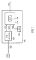
- Fig. 1 shows an adaptive filter device 100 having as input an input signal 102, e.g. an analogue television signal and as output an output signal y(n).
- Input signal 102 may also be an orthogonal frequency division multiplex (OFDM) signal.
- OFDM orthogonal frequency division multiplex
- Adaptive filter device 100 comprises a preprocessor 104, an adaptive filter 106 and a signal storage 107 that stores a predetermined reference signal d(n).
- Preprocessor 104 generates from said television signal 102 a first input signal x(n) and a second input signal d x (n) for said adaptive filter 106.
- the second input signal d x (n) is a received reference signal, e.g. a non-visible signal, that is transmitted together with analogue television signal 102.
- the purpose of the received reference signal may e.g. be to remove multi-path echoes from a received analogue television signal.
- a further input to said adaptive filter 106 is the predetermined reference signal d(n).
- the predetermined reference signal d(n) may e.g. correspond to a difference signal of two predetermined ghost cancelling reference signals GCR_A and GCR_B transmitted in different lines of the television signal x(n).
- the filter characteristic of adaptive filter 106 depends on filter coefficients of an FIR filter 108 located in said adaptive filter 108.
- the filter coefficients of finite impulse response filter (FIR) 108 are determined based on a predetermined iterative adaptation algorithm for determining filter coefficients of an adaptive filter, wherein, in at least one iteration step of said predetermined iterative adaptation algorithm a sum value is determined, wherein each summand of said sum value depends on one of said filter coefficients, and, if said sum value is above a predetermined threshold, the filter coefficients are modified.
- the filter coefficients are determined based on the received reference signal d x (n) and predetermined reference signal d(n), e.g. during receiving said received reference signal d x (n). The determined filter coefficients are then used to filter signal x(n).
- the algorithm described in " Adaptive IIR Filtering" by John J. Shynk, published in IEEE ASSP Magazine, April 1989 may be used.
- the predetermined iterative adaptation algorithm may be applied in accordance with an equation error formulation of the adaptive filter device as shown in Fig. 3 of the cited reference " Adaptive IIR filtering" by John J. Shynk and corresponding description thereof.
- the filter coefficients may be modified such that after modification the sum value is below or equal to the predetermined threshold.
- the sum value may e.g. be descriptive of an energy of the filter or to a sum of squares of absolute values of the filter coefficients, and the predetermined threshold may correspond to a threshold limiting the energy of the FIR filter.
- the sum value may also correspond to the root of a sum of absolute values to the x-th power as defined below in Eq. (1).
- the filter coefficients may be modified by multiplying the filter coefficients with a constant value.
- the constant value may be chosen to be smaller or equal to one. If the constant value is chosen equal to zero, the sum value may be equal to the predetermined threshold.
- the filter coefficients may also be modified by dividing the filter coefficients by the sum value.
- modified filter coefficients may be used for a next iteration step of the predetermined iterative adaptation algorithm.
- the adaptive filter device may also comprise an infinite impulse response (IIR) filter in cascade with the finite impulse response filter (see also Fig. 2 ).
- IIR infinite impulse response
- the adaptive filter device may be based on equation error formulation as described in the aforementioned reference "Adaptive IIR filtering" by John J. Shynk .
- the filter coefficients may also be determined in order to equalize notches, e.g. present in an analogue television signal.
- the FIR filter has a tap size M and the IIR filter has a tap size N, wherein M and N are positive integer values and may be set independently from each other.
- the sum value may be calculated according to the following formula: ⁇ m - 0 M - 1 b m x x , wherein b m denotes a respective filter coefficient and x is a real value greater zero (x>0).
- ⁇ 0 may be set to equal to 3.0. With such setting good results may be obtained.
- ⁇ 0 may be set depending on the application and be determined heuristically.
- the adaptive filter device may be an equalizer for removing at least one multi-path echo of a received analog television signal.
- a receiver for receiving an analogue television signal may comprise an adaptive filter device as defined above.
- filter coefficients may be determined based on first filter coefficients that depend on a sum value, wherein each summand of said sum value depends on one of said filter coefficients, and, wherein, if the sum value is below a predefined threshold, the filter coefficients are to be chosen to be equal to the first filter coefficients, and, if the sum value is equal to or above the predetermined threshold, then the filter coefficients are determined such that the sum value becomes smaller than or equal to the predefined threshold.
- a further embodiment of the invention concerns a method for determining filter coefficients e.g. of a finite impulse response (FIR) filter of an adaptive filter device, comprising determining the filter coefficients based on a predetermine iterative adaptation algorithm for determining filter coefficients of an adaptive filter, determining, in at least one iteration step of the predetermined iterative adaptation algorithm, a sum value, wherein each summand of the sum value depends on one of the filter coefficients, and modifying, if the sum value is above a predetermined threshold, the filter coefficients.
- FIR finite impulse response
- a further embodiment of the invention concerns a computer program product, e.g. a computer readable storage medium or downloadable executable or preinstalled program on a computer, including computer program instructions that cause a computer to execute a method as defined above.
- a computer program product e.g. a computer readable storage medium or downloadable executable or preinstalled program on a computer, including computer program instructions that cause a computer to execute a method as defined above.
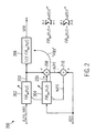
- Fig. 2 corresponds to a further embodiment of the invention and shows an equation error adaptive IIR filter 200 comprising a first finite impulse response (FIR) filter 202, a second FIR filter 204, and an all-pole filter 206 (IIR filter).
- FIR finite impulse response
- IIR filter all-pole filter
- An input to the first FIR filter 202 is a television signal x(n) or, if a reference signal is received, the received reference signal d x (n).
- An input to the second FIR filter 204 is the predetermined reference signal d(n).
- a first output signal 203 is used as input for the all-pole filter 206. All-pole filter 206 has as output a filtered television signal y(n). Filtered television signal y(n) may e.g. comprise less disturbances than television signal x(n) resulting from e.g. multi-path echoes.
- the first output signal 203 is used together with a second output signal 205 of said second FIR filter 204 in order to generate a first error signal y e (n), if the received reference signal d x (n) is received.
- First error signal y e (n) is determined by adding said first and second output signals 203, 205.
- an equation error signal e e (n) is determined by subtracting the first error signal y e (n) from reference signal d(n).
- the filter coefficients of first FIR filter 202 and all-pole filter 206 are used to filter input signal x(n) in order to obtain filtered television signal y(n).
- a sum value of the filter coefficients of the first FIR filter 202 may be limited.
- the sum value may describe or be correlated with the energy of FIR filter 202.
- first FIR filter 202 If the sum value of first FIR filter 202 is limited, the adaptation filter may be kept stable whereas a large sum value could lead to instable IIR filter coefficients, i.e. to an instable behavior of all-pole filter 206.
- first FIR filter 202 the maximum sum value (maximum FIR filter energy) of first FIR filter 202 is limited if the sum value exceeds a certain threshold ⁇ 0 during the adaptation process. Therefore, the FIR filter coefficients of first FIR filter 202 may be multiplied with an additional normalization factor K 0 slightly smaller than or equal to 1.0 to allow for an ongoing adaptation process of the FIR filter. K 0 may also be larger than 1.
- f(b m ) corresponds to a suitable function for keeping the filter stable e.g. by limiting the absolute values of the filter coefficients or an energy measure.
- x may e.g. be chosen to be equal to 2.
- the adaptive filter may be adapted to equalize notches. Even in such difficult situations where frequently instabilities are caused, by limiting the sum value as described above, the filter can be kept stable.
- the filter tap size of the first FIR filter 202 is denoted by M
- the filter tap size of the second FIR filter 204 is denoted by N. Because the coefficients of second FIR filter 204 are copied to all-pole filter 206 as described above, the tap size of all-pole filter 206 is also equal to N.
- Fig. 2 may be realized in software or hardware likewise.
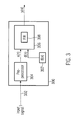
- Fig. 3 shows an adaptive filter device 300 according to a further embodiment of the invention having as input an input signal 302, e.g. an analogue television signal and as output an output signal y(n).
- Input signal 302 may also be an orthogonal frequency division multiplex (OFDM) signal.
- OFDM orthogonal frequency division multiplex
- Adaptive filter device 300 comprises a preprocessor 304, an adaptive filter 306 and a signal storage 307 that stores a predetermined reference signal d(n).
- Preprocessor 304 generates from said television signal 302 a first input signal x(n) for said adaptive filter 306.
- a further input to said adaptive filter 306 is the predetermined reference signal d(n).
- the predetermined reference signal d(n) may e.g. correspond to a difference signal of two predetermined ghost cancelling reference signals GCR_A and GCR_B transmitted in different lines of the television signal x(n).
- the filter characteristic of adaptive filter 306 depends on filter coefficients of an FIR filter 308 located in said adaptive filter 308.
- the filter coefficients of finite impulse response filter (FIR) 308 are determined based on a predetermined iterative adaptation algorithm for determining filter coefficients of an adaptive filter, wherein, in at least one iteration step of said predetermined iterative adaptation algorithm a sum value is determined, wherein each summand of said sum value depends on one of said filter coefficients, and, if said sum value is above a predetermined threshold, the filter coefficients are modified.
- the filter coefficients are determined based on the received reference signal d x (n) and predetermined reference signal d(n), e.g. during receiving said received reference signal d x (n). The determined filter coefficients are then used to filter signal x(n).
- the algorithm described in " Adaptive IIR Filtering" by John J. Shynk, published in IEEE ASSP Magazine, April 1989 may be used.
- the predetermined iterative adaptation algorithm may be applied in accordance with an equation error formulation of the adaptive filter device as shown in Fig. 3 of the cited reference " Adaptive IIR filtering" by John J. Shynk and corresponding description thereof.
- the filter coefficients may be modified such that after modification the sum value is below or equal to the predetermined threshold.
- the sum value may e.g. be descriptive of an energy of the filter or to a sum of squares of absolute values of the filter coefficients, and the predetermined threshold may correspond to a threshold limiting the energy of the FIR filter.
- the sum value may also correspond to the root of a sum of absolute values to the x-th as defined below in Eq. (1).
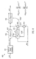
- Fig. 4 corresponds to a further embodiment of the invention and shows an equation error adaptive IIR filter 400 comprising a first finite impulse response (FIR) filter 402, a second FIR filter 404, and an all-pole filter 406 (IIR filter).
- FIR finite impulse response
- IIR filter all-pole filter 406
- An input to the first FIR filter 402 is a television signal x(n) or, if a reference signal is received, the received reference signal d x (n).
- Received reference signal d x (n) may be extracted from television signal x(n) by a reference signal extractor 401.
- Received reference signal d x (n) is used to determine, e.g. update or modify, the filter coefficients of first and second FIR filters 402, 405, and television signal x(n) is used in order to determine y(n) corresponding to x(n) filtered by filters 402 and 406. Also, when the filter coefficients are calculated, e.g. if a reference signal d x (n) is received, filter 406 will filter the received reference signal d x (n) in order to guarantee a continuous output signal y(n).
- An input to the second FIR filter 404 is the predetermined reference signal d(n).
- a first output signal 403 is used as input for the all-pole filter 406.
- All-pole filter 406 has as output a filtered television signal y(n).
- Filtered television signal y(n) may e.g. comprise less disturbances than television signal x(n) resulting from e.g. multi-path echoes.
- the first output signal 403 is used together with a second output signal 405 of said second FIR filter 404 in order to generate a first error signal y e (n), if the received reference signal d x (n) is received.
- First error signal y e (n) is determined by adding said first and second output signals 403, 405.
- an equation error signal ee(n) is determined by subtracting the first error signal y e (n) from reference signal d(n).
- the inverse of 1-FIR bw (n,z) is copied to the all-pole filter 406 which is in cascade with the first FIR filter 402.
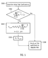
- Fig. 5 shows a flowchart according to which the filter coefficients of e.g. first FIR filter 202 or 402 may be determined.
- initial filter coefficients b K are determined according to a predetermined iterative adaptation algorithm which may be chosen depending on the application scenario.
- step S308 the filter coefficients b k are used as filter coefficients for the first FIR filter 202.
- step S302 If, in step S302, the sum is not smaller than ⁇ 0 , then, in step S304 new filter coefficients are computed according to equation (2) given above.
- step 5306 the filter coefficients b k are replaced by the new filter coefficients b k_new .
- Fig. 6 shows the FIR filter energy of the first FIR filter 202 in case of two different multi-path conditions.
- the first channel ch1 leads to stable filter coefficients (see reference sign 600 in Fig. 6 ).
- the sum value also referred to as FIR filter energy, never exceeds the threshold ⁇ 0 .
- the threshold ⁇ 0 is set to 3.0. Therefore, a limitation of the FIR filter energy may not be necessary.
- the second channel ch2 leads to a very high FIR filter energy due to a notch in the considered frequency band. Without any counter measure this channel ch2 causes an instable equalization filter.
- a long term stable equalization filter may be obtained (see reference sign 602 in Fig. 6 ).
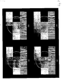
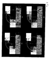
- picture (a) corresponds to the original television signal.
- Picture (b) corresponds to the received television signal after multi-path propagation.
- Picture (c) corresponds to a picture with equalized television signal with FIR filter energy limitation as explained above.
- Picture (d) corresponds to a picture obtained by equalizing a television signal without FIR filter energy limitation immediately before the filter gets instable.
- picture (d) corresponds more or less to a picture according to prior art. It should be noted that the situation according to the prior art is in reality much worse than shown in picture (d) because after the filter gets instable, the picture is much worse and may not even be visible at all.
- Fig. 8 corresponds to Fig. 7 in color.
Abstract
Adaptive filter device, comprising a finite impulse response (FIR) filter which is based on filter coefficients, which are determined based on a predetermined iterative adaptation algorithm for determining filter coefficients of an adaptive filter, wherein, in at least one iteration step of said predetermined iterative adaptation algorithm a sum value is determined, wherein each summand of said sum value depends on one of said filter coefficients, and, if said sum value is above a predetermined threshold, the filter coefficients are modified.
Description
- An embodiment of the invention relates to an adaptive filter device. A further embodiment of the invention relates to a method for determining filter coefficients of an adaptive filter.
- Adaptive filters are often used in practical implementations due to their excellent performance, especially in an environment of unknown statistics or in inherently non-stationary environment. The underlying algorithms may either be based on an equation-error (EE) formulation or an output error (OE) formulation. Since the equation-error formulation is a convex problem with one global minimum and due to its straight forward design it is often used in practical implementations. The main disadvantage of the EE formulation is the fact that a general stability of the filter is only guaranteed in case of special filter constraints, which often results in a conflict with practical implementations.
- It is an object of the invention to provide an adaptive filter with high stability.
- This object is solved in accordance with
claims 1, 12 and 21, respectively. - Further details of the invention will become apparent from a consideration of the drawings and ensuing description.
-
-
Fig. 1 shows an adaptive filter device according to an embodiment of the invention; -
Fig. 2 shows an adaptive filter according to a further embodiment of the invention; -
Fig. 3 shows an adaptive filter device according to a further embodiment of the invention; -
Fig. 4 shows an adaptive filter according to a further embodiment of the invention; -
Fig. 5 shows a flowchart illustrating how filter coefficients may be modified during one iteration step; -
Fig. 6 shows a diagram where the energy of two filters is depicted during the iterative process to determine respective filter coefficients; -
Fig. 7 shows a comparison of a television picture that has been filtered with different filter coefficients; -
Fig. 8 corresponds toFig. 7 in color. - In the following, embodiments of the invention are described. It is important to note, that all described embodiments in the following may be combined in any way, i.e. there is no limitation that certain described embodiments may not be combined with others.
-
Fig. 1 shows anadaptive filter device 100 having as input aninput signal 102, e.g. an analogue television signal and as output an output signal y(n).Input signal 102 may also be an orthogonal frequency division multiplex (OFDM) signal. -
Adaptive filter device 100 comprises apreprocessor 104, anadaptive filter 106 and asignal storage 107 that stores a predetermined reference signal d(n).Preprocessor 104 generates from said television signal 102 a first input signal x(n) and a second input signal dx(n) for saidadaptive filter 106. The second input signal dx(n) is a received reference signal, e.g. a non-visible signal, that is transmitted together withanalogue television signal 102. The purpose of the received reference signal may e.g. be to remove multi-path echoes from a received analogue television signal. A further input to saidadaptive filter 106 is the predetermined reference signal d(n). The predetermined reference signal d(n) may e.g. correspond to a difference signal of two predetermined ghost cancelling reference signals GCR_A and GCR_B transmitted in different lines of the television signal x(n). - The filter characteristic of
adaptive filter 106 depends on filter coefficients of anFIR filter 108 located in saidadaptive filter 108. - In order to obtain a stable behaviour of
adaptive filter device 100, the filter coefficients of finite impulse response filter (FIR) 108 are determined based on a predetermined iterative adaptation algorithm for determining filter coefficients of an adaptive filter, wherein, in at least one iteration step of said predetermined iterative adaptation algorithm a sum value is determined, wherein each summand of said sum value depends on one of said filter coefficients, and, if said sum value is above a predetermined threshold, the filter coefficients are modified. The filter coefficients are determined based on the received reference signal dx(n) and predetermined reference signal d(n), e.g. during receiving said received reference signal dx(n). The determined filter coefficients are then used to filter signal x(n). - As predetermined iterative adaptation algorithm, the algorithm described in "Adaptive IIR Filtering" by John J. Shynk, published in IEEE ASSP Magazine, April 1989 may be used. In particular, the predetermined iterative adaptation algorithm may be applied in accordance with an equation error formulation of the adaptive filter device as shown in
Fig. 3 of the cited reference "Adaptive IIR filtering" by John J. Shynk and corresponding description thereof. - In a further embodiment, the filter coefficients may be modified such that after modification the sum value is below or equal to the predetermined threshold. The sum value may e.g. be descriptive of an energy of the filter or to a sum of squares of absolute values of the filter coefficients, and the predetermined threshold may correspond to a threshold limiting the energy of the FIR filter. The sum value may also correspond to the root of a sum of absolute values to the x-th power as defined below in Eq. (1).
- Further, the filter coefficients may be modified by multiplying the filter coefficients with a constant value. The constant value may be chosen to be smaller or equal to one. If the constant value is chosen equal to zero, the sum value may be equal to the predetermined threshold.
- The filter coefficients may also be modified by dividing the filter coefficients by the sum value.
- Further, the modified filter coefficients may be used for a next iteration step of the predetermined iterative adaptation algorithm.
- The adaptive filter device may also comprise an infinite impulse response (IIR) filter in cascade with the finite impulse response filter (see also
Fig. 2 ). - In a further embodiment, the adaptive filter device may be based on equation error formulation as described in the aforementioned reference "Adaptive IIR filtering" by John J. Shynk.
- The filter coefficients may also be determined in order to equalize notches, e.g. present in an analogue television signal.
- In a further embodiment, it may also be possible that the FIR filter has a tap size M and the IIR filter has a tap size N, wherein M and N are positive integer values and may be set independently from each other.
- The sum value may be calculated according to the following formula:

- In a further embodiment, the filter coefficients bK may be modified based on the following formula:

wherein - bk_new:
- new filter coefficients of adaptive filter for next iteration step;
- bk:
- filter coefficients determined according to predetermined iterative adaptation algorithm;
- Ko:
- normalization factor;
- Γ0:
- said predetermined threshold,
- M:
- tap size of FIR filter,
- x:
- real value greater zero.
- In an embodiment, Γ0 may be set to equal to 3.0. With such setting good results may be obtained. Of course, in general Γ0 may be set depending on the application and be determined heuristically.
- In a further embodiment, the adaptive filter device may be an equalizer for removing at least one multi-path echo of a received analog television signal.
- In a further embodiment, a receiver for receiving an analogue television signal may comprise an adaptive filter device as defined above.
- In other words, according to an embodiment of the invention, filter coefficients may be determined based on first filter coefficients that depend on a sum value, wherein each summand of said sum value depends on one of said filter coefficients, and, wherein, if the sum value is below a predefined threshold, the filter coefficients are to be chosen to be equal to the first filter coefficients, and, if the sum value is equal to or above the predetermined threshold, then the filter coefficients are determined such that the sum value becomes smaller than or equal to the predefined threshold.
- A further embodiment of the invention concerns a method for determining filter coefficients e.g. of a finite impulse response (FIR) filter of an adaptive filter device, comprising determining the filter coefficients based on a predetermine iterative adaptation algorithm for determining filter coefficients of an adaptive filter, determining, in at least one iteration step of the predetermined iterative adaptation algorithm, a sum value, wherein each summand of the sum value depends on one of the filter coefficients, and modifying, if the sum value is above a predetermined threshold, the filter coefficients.
- The modification with the method may be done as explained above.
- A further embodiment of the invention concerns a computer program product, e.g. a computer readable storage medium or downloadable executable or preinstalled program on a computer, including computer program instructions that cause a computer to execute a method as defined above.
-
Fig. 2 corresponds to a further embodiment of the invention and shows an equation erroradaptive IIR filter 200 comprising a first finite impulse response (FIR)filter 202, asecond FIR filter 204, and an all-pole filter 206 (IIR filter). - An input to the
first FIR filter 202 is a television signal x(n) or, if a reference signal is received, the received reference signal dx(n). An input to thesecond FIR filter 204 is the predetermined reference signal d(n). Afirst output signal 203 is used as input for the all-pole filter 206. All-pole filter 206 has as output a filtered television signal y(n). Filtered television signal y(n) may e.g. comprise less disturbances than television signal x(n) resulting from e.g. multi-path echoes. - The
first output signal 203 is used together with asecond output signal 205 of saidsecond FIR filter 204 in order to generate a first error signal ye(n), if the received reference signal dx(n) is received. First error signal ye(n) is determined by adding said first and second output signals 203, 205. In order to determine the filter coefficients of the first and second FIR filters 202, 204, an equation error signal ee(n) is determined by subtracting the first error signal ye(n) from reference signal d(n). - The
first FIR filter 202 is given by the following formula:
- The
second FIR filter 204 is given by the following formula:
- After each update of the weights, the inverse of 1-FIRbw(n,z) is copied to the all-
pole filter 206 which is in cascade with thefirst FIR filter 202. - The copying operation is denoted by an arrow in
Fig. 2 marked with "copy". - If the input signal corresponds to x(n), e.g. before or after receiving a received reference signal dx(n), the filter coefficients of
first FIR filter 202 and all-pole filter 206 are used to filter input signal x(n) in order to obtain filtered television signal y(n). - In order to provide a stable filter, according to an embodiment of the invention, a sum value of the filter coefficients of the
first FIR filter 202 may be limited. The sum value may describe or be correlated with the energy ofFIR filter 202. - If the sum value of
first FIR filter 202 is limited, the adaptation filter may be kept stable whereas a large sum value could lead to instable IIR filter coefficients, i.e. to an instable behavior of all-pole filter 206. - Therefore, the maximum sum value (maximum FIR filter energy) of
first FIR filter 202 is limited if the sum value exceeds a certain threshold Γ0 during the adaptation process. Therefore, the FIR filter coefficients offirst FIR filter 202 may be multiplied with an additional normalization factor K0 slightly smaller than or equal to 1.0 to allow for an ongoing adaptation process of the FIR filter. K0 may also be larger than 1. - Thus, during the adaptation process of the
first FIR filter 202, it is checked if the threshold is exceeded according to the following formula:
wherein f(bm) corresponds to a suitable function for keeping the filter stable e.g. by limiting the absolute values of the filter coefficients or an energy measure. f(bm) may e.g. be chosen to be:
wherein bm denotes a respective filter coefficient and x is a real value greater than zero (x>0). x may e.g. be chosen to be equal to 2. - If the threshold Γ0 is not exceeded, the FIR filter coefficients are not modified. However, if the threshold Γ0 is exceeded, the FIR filter coefficients are recomputed to

wherein - bk_new:
- new filter coefficients of adaptive filter for next iteration step;
- bk:
- filter coefficients determined according to predetermined iterative adaptation algorithm;
- K0:
- normalization factor;
- Γ0:
- said predetermined threshold;
- M:
- tap size of FIR filter; and
- x:
- real value greater than zero.
- According to a further embodiment of the invention, the adaptive filter may be adapted to equalize notches. Even in such difficult situations where frequently instabilities are caused, by limiting the sum value as described above, the filter can be kept stable.
- As is apparent from the above formulas defining
first FIR filter 202 andsecond FIR filter 204, respectively, the filter tap size of thefirst FIR filter 202 is denoted by M, whereas the filter tap size of thesecond FIR filter 204 is denoted by N. Because the coefficients ofsecond FIR filter 204 are copied to all-pole filter 206 as described above, the tap size of all-pole filter 206 is also equal to N. - It is possible to choose M and N as different values. Even in this case filter stability may still be high due to the above explained limitation of the sum value.
- It should be noted that the filter shown in
Fig. 2 may be realized in software or hardware likewise. -
Fig. 3 shows anadaptive filter device 300 according to a further embodiment of the invention having as input aninput signal 302, e.g. an analogue television signal and as output an output signal y(n).Input signal 302 may also be an orthogonal frequency division multiplex (OFDM) signal. -
Adaptive filter device 300 comprises apreprocessor 304, anadaptive filter 306 and asignal storage 307 that stores a predetermined reference signal d(n).Preprocessor 304 generates from said television signal 302 a first input signal x(n) for saidadaptive filter 306. A further input to saidadaptive filter 306 is the predetermined reference signal d(n). The predetermined reference signal d(n) may e.g. correspond to a difference signal of two predetermined ghost cancelling reference signals GCR_A and GCR_B transmitted in different lines of the television signal x(n). - The filter characteristic of
adaptive filter 306 depends on filter coefficients of anFIR filter 308 located in saidadaptive filter 308. - In order to obtain a stable behaviour of
adaptive filter device 300, the filter coefficients of finite impulse response filter (FIR) 308 are determined based on a predetermined iterative adaptation algorithm for determining filter coefficients of an adaptive filter, wherein, in at least one iteration step of said predetermined iterative adaptation algorithm a sum value is determined, wherein each summand of said sum value depends on one of said filter coefficients, and, if said sum value is above a predetermined threshold, the filter coefficients are modified. The filter coefficients are determined based on the received reference signal dx(n) and predetermined reference signal d(n), e.g. during receiving said received reference signal dx(n). The determined filter coefficients are then used to filter signal x(n). - As predetermined iterative adaptation algorithm, the algorithm described in "Adaptive IIR Filtering" by John J. Shynk, published in IEEE ASSP Magazine, April 1989 may be used. In particular, the predetermined iterative adaptation algorithm may be applied in accordance with an equation error formulation of the adaptive filter device as shown in
Fig. 3 of the cited reference "Adaptive IIR filtering" by John J. Shynk and corresponding description thereof. - In a further embodiment, the filter coefficients may be modified such that after modification the sum value is below or equal to the predetermined threshold. The sum value may e.g. be descriptive of an energy of the filter or to a sum of squares of absolute values of the filter coefficients, and the predetermined threshold may correspond to a threshold limiting the energy of the FIR filter. The sum value may also correspond to the root of a sum of absolute values to the x-th as defined below in Eq. (1).
-
Fig. 4 corresponds to a further embodiment of the invention and shows an equation erroradaptive IIR filter 400 comprising a first finite impulse response (FIR)filter 402, asecond FIR filter 404, and an all-pole filter 406 (IIR filter). - An input to the
first FIR filter 402 is a television signal x(n) or, if a reference signal is received, the received reference signal dx(n). Received reference signal dx(n) may be extracted from television signal x(n) by areference signal extractor 401. Received reference signal dx(n) is used to determine, e.g. update or modify, the filter coefficients of first and second FIR filters 402, 405, and television signal x(n) is used in order to determine y(n) corresponding to x(n) filtered byfilters filter 406 will filter the received reference signal dx(n) in order to guarantee a continuous output signal y(n). - An input to the
second FIR filter 404 is the predetermined reference signal d(n). Afirst output signal 403 is used as input for the all-pole filter 406. All-pole filter 406 has as output a filtered television signal y(n). Filtered television signal y(n) may e.g. comprise less disturbances than television signal x(n) resulting from e.g. multi-path echoes. - The
first output signal 403 is used together with asecond output signal 405 of saidsecond FIR filter 404 in order to generate a first error signal ye(n), if the received reference signal dx(n) is received. First error signal ye(n) is determined by adding said first and second output signals 403, 405. In order to determine the filter coefficients of the first and second FIR filters 402, 404, an equation error signal ee(n) is determined by subtracting the first error signal ye(n) from reference signal d(n). - The
first FIR filter 402 is given by the following formula:
- The
second FIR filter 404 is given by the following formula:
- After at least one update of the weights, e.g. after several updates, the inverse of 1-FIRbw(n,z) is copied to the all-
pole filter 406 which is in cascade with thefirst FIR filter 402. - The copying operation is denoted by an arrow in
Fig. 4 marked with "copy". -
Fig. 5 shows a flowchart according to which the filter coefficients of e.g.first FIR filter - In step S302, it is checked if the sum value

- If the sum value is smaller then, in step S308, the filter coefficients bk are used as filter coefficients for the
first FIR filter 202. - If, in step S302, the sum is not smaller than Γ0, then, in step S304 new filter coefficients are computed according to equation (2) given above.
- Then, in step 5306 the filter coefficients bk are replaced by the new filter coefficients bk_new.
-
Fig. 6 shows the FIR filter energy of thefirst FIR filter 202 in case of two different multi-path conditions. The first channel ch1 leads to stable filter coefficients (seereference sign 600 inFig. 6 ). The sum value, also referred to as FIR filter energy, never exceeds the threshold Γ0. As seen, inFig. 6 , the threshold Γ0 is set to 3.0. Therefore, a limitation of the FIR filter energy may not be necessary. In contrast, the second channel ch2 leads to a very high FIR filter energy due to a notch in the considered frequency band. Without any counter measure this channel ch2 causes an instable equalization filter. However, if the maximum FIR filter energy is limited as explained above, a long term stable equalization filter may be obtained (seereference sign 602 inFig. 6 ). - The result is shown in
Figs. 7 and8 . - In
Fig. 7 , picture (a) corresponds to the original television signal. Picture (b) corresponds to the received television signal after multi-path propagation. Picture (c) corresponds to a picture with equalized television signal with FIR filter energy limitation as explained above. - Picture (d) corresponds to a picture obtained by equalizing a television signal without FIR filter energy limitation immediately before the filter gets instable. In other words, picture (d) corresponds more or less to a picture according to prior art. It should be noted that the situation according to the prior art is in reality much worse than shown in picture (d) because after the filter gets instable, the picture is much worse and may not even be visible at all.
-
Fig. 8 corresponds toFig. 7 in color.
Claims (28)
- Adaptive filter device,
comprising a finite impulse response (FIR) filter which is based on filter coefficients, which are determined based on a predetermined iterative adaptation algorithm for determining filter coefficients of an adaptive filter, wherein, in at least one iteration step of said predetermined iterative adaptation algorithm a sum value is determined, wherein at least one summand of said sum value depends on at least one of said filter coefficients, and, if said sum value is above a predetermined threshold, the filter coefficients are modified. - Adaptive filter device according to claim 1, wherein said filter coefficients are modified such that after modification said sum value is below said predetermined threshold.
- Adaptive filter device according to any of the preceding claims, wherein said filter coefficients are modified by multiplying the filter coefficients with a constant value (Ko).
- Adaptive filter device according to claim 3, wherein said constant value is smaller than or equal to 1.
- Adaptive filter device according to any of the preceding claims, wherein said filter coefficients are modified by dividing the filter coefficients by said sum value.
- Adaptive filter device according to any of the preceding claims, wherein the modified filter coefficients are used for a next iteration step of said predetermined iterative adaptation algorithm.
- Adaptive filter device according to any of the preceding claims, further comprising an infinite impulse response (IIR) filter in cascade with said finite impulse response (FIR) filter.
- Adaptive filter device according to any of the preceding claims, wherein said adaptive filter device is based on an equation error formulation.
- Adaptive filter device according to any of the preceding claims, wherein said filter coefficients are determined in order to equalize notches.
- Adaptive filter device according to any of claims 7 to 9, wherein said FIR filter has a tap size M and said IIR filter has a tap size N, wherein M and N are positive integer values set independently from each other.
- Adaptive filter device according to any of the preceding claims, wherein said sum value is calculated by the following formula:

wherein bm denotes a respective filter coefficient and x is a real value greater zero. - Adaptive filter device according to any of the preceding claims, wherein the filter coefficients bk are modified based on the following formula:

whereinbk_new: new filter coefficients of adaptive filter for next iteration step;bk: filter coefficients determined according to predetermined iterative adaptation algorithm;K0: normalization factor;Γ0: said predetermined threshold,M: tap size of FIR filter,x: real value greater than zero. - Adaptive filter device according to any of the preceding claims, wherein said adaptive filter device is an equalizer for removing at least one multi-path echo of a received analogue television signal.
- Receiver for receiving an analog television signal, comprising an adaptive filter device according to any of claims 1 to 13.
- Method for determining filter coefficients of a finite impulse response (FIR) filter of an adaptive filter device, comprising
determining said filter coefficients based on a predetermined iterative adaptation algorithm for determining filter coefficients of an adaptive filter,
determining, in at least one iteration step of said predetermined iterative adaptation algorithm, a sum value, wherein each summand of said sum value depends on one of said filter coefficients,
modifying, if said sum value is above a predetermined threshold, the filter coefficients. - Method according to claim 15, wherein said filter coefficients are modified such that after modification said sum value is below said predetermined threshold.
- Method according to any of claims 15 to 16, wherein said filter coefficients are modified by multiplying the filter coefficients with a constant value (K0).
- Method according to claim 17, wherein said constant value is smaller than or equal to 1.
- Method according to any of claims 15 to 18, wherein said filter coefficients are modified by dividing the filter coefficients by said sum value.
- Method according to any of claims 15 to 19, wherein the modified filter coefficients are used for a next iteration step of said predetermined iterative adaptation algorithm.
- Method according to any of claims 15 to 20, wherein said adaptive filter device further comprises an infinite impulse response (IIR) filter in cascade with said finite impulse response (FIR) filter.
- Method according to any of claims 15 to 21, wherein said filter coefficients are determined based on an equation-error formulation.
- Method according to any of claims 15 to 22, wherein said filter coefficients are determined in order to equalize notches.
- Method according to any of claims 15 to 23, wherein said sum value is calculated by the following formula:

wherein bm denotes a respective filter coefficient and x is a real value greater zero. - Method according to any of claims 15 to 24, wherein the filter coefficients bk are modified based on the following formula:

whereinbk_new: new filter coefficients of adaptive filter for next iteration step;bk: filter coefficients determined according to predetermined iterative adaptation algorithm;K0: normalization factor;Γ0: said predetermined threshold,M: tap size of FIR filter,x: real value greater than zero. - A computer program product including computer program instructions that cause a computer to execute a method according to any of claims 15 to 25.
- Adaptive filter device comprising a finite impulse response (FIR) filter which is based on filter coefficients,
wherein said filter coefficients are determined based on first filter coefficients and depending on a sum value, wherein each summand of said sum value depends on one of said filter coefficients, and
wherein, if said sum value is below a predefined threshold, said filter coefficients are equal to said first filter coefficients, and, if said sum value is equal to or above said predefined threshold, said filter coefficients are determined such that said sum value becomes smaller than said predefined threshold. - Adaptive filter device which is based on filter coefficients,
wherein said filter coefficients are determined based on first filter coefficients and depending on a sum value, wherein each summand of said sum value depends on one of said filter coefficients, and
wherein, if said sum value is below a predefined threshold, said filter coefficients are equal to said first filter coefficients, and, if said sum value is equal to or above said predefined threshold, said filter coefficients are determined such that said sum value becomes smaller than said predefined threshold.
Priority Applications (3)
| Application Number | Priority Date | Filing Date | Title |
|---|---|---|---|
| EP07006802A EP1976122A1 (en) | 2007-03-31 | 2007-03-31 | Adaptive filter device |
| US12/078,386 US8402074B2 (en) | 2007-03-31 | 2008-03-31 | Adaptive filter device and method for determining filter coefficients |
| CNA2008100884721A CN101277103A (en) | 2007-03-31 | 2008-03-31 | Adaptive filter device and method for determining filter coefficients |
Applications Claiming Priority (1)
| Application Number | Priority Date | Filing Date | Title |
|---|---|---|---|
| EP07006802A EP1976122A1 (en) | 2007-03-31 | 2007-03-31 | Adaptive filter device |
Publications (1)
| Publication Number | Publication Date |
|---|---|
| EP1976122A1 true EP1976122A1 (en) | 2008-10-01 |
Family
ID=39016250
Family Applications (1)
| Application Number | Title | Priority Date | Filing Date |
|---|---|---|---|
| EP07006802A Withdrawn EP1976122A1 (en) | 2007-03-31 | 2007-03-31 | Adaptive filter device |
Country Status (3)
| Country | Link |
|---|---|
| US (1) | US8402074B2 (en) |
| EP (1) | EP1976122A1 (en) |
| CN (1) | CN101277103A (en) |
Families Citing this family (15)
| Publication number | Priority date | Publication date | Assignee | Title |
|---|---|---|---|---|
| US7676360B2 (en) * | 2005-12-01 | 2010-03-09 | Sasken Communication Technologies Ltd. | Method for scale-factor estimation in an audio encoder |
| EP1976122A1 (en) * | 2007-03-31 | 2008-10-01 | Sony Deutschland Gmbh | Adaptive filter device |
| JP5746193B2 (en) | 2009-10-15 | 2015-07-08 | トムソン ライセンシングThomson Licensing | Efficient adaptive filtering method and apparatus for video encoding and decoding |
| US20120136658A1 (en) * | 2010-11-30 | 2012-05-31 | Cox Communications, Inc. | Systems and methods for customizing broadband content based upon passive presence detection of users |
| US9343076B2 (en) | 2011-02-16 | 2016-05-17 | Dolby Laboratories Licensing Corporation | Methods and systems for generating filter coefficients and configuring filters |
| CN102170520B (en) * | 2011-04-29 | 2013-12-25 | 杭州海康威视数字技术股份有限公司 | Cascade filter and dynamic setting method for calibrated denoising intensity thereof |
| US8638166B2 (en) * | 2012-06-13 | 2014-01-28 | Analog Devices, Inc. | Apparatus and methods for notch filtering |
| CN105322967B (en) * | 2014-07-17 | 2018-09-28 | 山东共达电声股份有限公司 | A kind of implementation method of filter and a kind of digital analog converter |
| CN106788336B (en) * | 2016-11-24 | 2020-02-28 | 北京航天自动控制研究所 | Linear system filtering estimation method based on output-feedback correction |
| US10014026B1 (en) * | 2017-06-20 | 2018-07-03 | Seagate Technology Llc | Head delay calibration and tracking in MSMR systems |
| CN108390663B (en) * | 2018-03-09 | 2021-07-02 | 电信科学技术研究院有限公司 | Method and device for updating coefficient vector of finite impulse response filter |
| CN109921763B (en) * | 2019-02-26 | 2021-10-22 | 华南理工大学 | FIR filter for reducing multipliers and output calculation method thereof |
| US11293812B2 (en) * | 2019-07-23 | 2022-04-05 | Schneider Electric USA, Inc. | Adaptive filter bank for modeling a thermal system |
| JP2022025908A (en) * | 2020-07-30 | 2022-02-10 | ヤマハ株式会社 | Filter processing method, filter processing device, and filter processing program |
| CN113507279A (en) * | 2021-06-11 | 2021-10-15 | 西安空间无线电技术研究所 | Speed reduction filtering method for high-precision inter-satellite distance observation data |
Citations (4)
| Publication number | Priority date | Publication date | Assignee | Title |
|---|---|---|---|---|
| EP0400850A2 (en) * | 1989-05-30 | 1990-12-05 | Advanced Micro Devices, Inc. | Generating coefficients for digital filters |
| EP0700156A2 (en) * | 1994-09-01 | 1996-03-06 | Nec Corporation | Beamformer using coefficient restrained adaptive filters for detecting interference signals |
| EP0955727A2 (en) * | 1998-05-07 | 1999-11-10 | Ford Motor Company | Adaptive noise reduction filter with low modulation disabling |
| US6219427B1 (en) * | 1997-11-18 | 2001-04-17 | Gn Resound As | Feedback cancellation improvements |
Family Cites Families (4)
| Publication number | Priority date | Publication date | Assignee | Title |
|---|---|---|---|---|
| US6957240B2 (en) * | 2001-08-08 | 2005-10-18 | Octasic Inc. | Method and apparatus for providing an error characterization estimate of an impulse response derived using least squares |
| US6970896B2 (en) * | 2001-08-08 | 2005-11-29 | Octasic Inc. | Method and apparatus for generating a set of filter coefficients |
| US8041757B2 (en) * | 2006-09-29 | 2011-10-18 | Netlogic Microsystems, Inc. | Low power and low complexity adaptive self-linearization |
| EP1976122A1 (en) * | 2007-03-31 | 2008-10-01 | Sony Deutschland Gmbh | Adaptive filter device |
-
2007
- 2007-03-31 EP EP07006802A patent/EP1976122A1/en not_active Withdrawn
-
2008
- 2008-03-31 CN CNA2008100884721A patent/CN101277103A/en active Pending
- 2008-03-31 US US12/078,386 patent/US8402074B2/en not_active Expired - Fee Related
Patent Citations (4)
| Publication number | Priority date | Publication date | Assignee | Title |
|---|---|---|---|---|
| EP0400850A2 (en) * | 1989-05-30 | 1990-12-05 | Advanced Micro Devices, Inc. | Generating coefficients for digital filters |
| EP0700156A2 (en) * | 1994-09-01 | 1996-03-06 | Nec Corporation | Beamformer using coefficient restrained adaptive filters for detecting interference signals |
| US6219427B1 (en) * | 1997-11-18 | 2001-04-17 | Gn Resound As | Feedback cancellation improvements |
| EP0955727A2 (en) * | 1998-05-07 | 1999-11-10 | Ford Motor Company | Adaptive noise reduction filter with low modulation disabling |
Non-Patent Citations (2)
| Title |
|---|
| HO K C ET AL: "BIAS REMOVAL IN EQUATION-ERROR ADAPTIVE IIR FILTERS", IEEE TRANSACTIONS ON SIGNAL PROCESSING, IEEE SERVICE CENTER, NEW YORK, NY, US, vol. 43, no. 1, January 1995 (1995-01-01), pages 51 - 62, XP000505176, ISSN: 1053-587X * |
| JOHN J. SHYNK: "Adaptive IIR Filtering", IEEE ASSP MAGAZINE, vol. 6, no. 2, April 1989 (1989-04-01), USA, pages 4 - 21, XP002468819 * |
Also Published As
| Publication number | Publication date |
|---|---|
| CN101277103A (en) | 2008-10-01 |
| US8402074B2 (en) | 2013-03-19 |
| US20080250090A1 (en) | 2008-10-09 |
Similar Documents
| Publication | Publication Date | Title |
|---|---|---|
| EP1976122A1 (en) | Adaptive filter device | |
| US5638439A (en) | Adaptive filter and echo canceller | |
| US20050232347A1 (en) | Apparatus and method for noise enhancement reduction in an adaptive equalizer | |
| EP1314246A1 (en) | Partioned block frequency domain adaptive filter | |
| JP2947093B2 (en) | Method and apparatus for system identification with adaptive filters | |
| JPH08125593A (en) | Estimating device for filter factor | |
| US6957240B2 (en) | Method and apparatus for providing an error characterization estimate of an impulse response derived using least squares | |
| EP1314247B1 (en) | Partitioned block frequency domain adaptive filter | |
| JPWO2008041612A1 (en) | Waveform equalizer | |
| JP4901416B2 (en) | Digital filter device | |
| JP3707443B2 (en) | Adaptive forgetting factor control adaptive filter and forgetting factor adaptive control method | |
| JP3292165B2 (en) | Line equalizer and its equalization method | |
| JPH08317254A (en) | Ghost elimination device | |
| JP2010041450A (en) | Adaptive equalizer, adaptive equalization method, and adaptive equalization program | |
| JP4324676B2 (en) | Adaptive filter | |
| US20050135469A1 (en) | Method and system for adaptive prefiltering of a signal for transmission | |
| JP3147864B2 (en) | Adaptive step size control adaptive filter and adaptive step size control method | |
| JP2002076999A (en) | Method and device for identifying system | |
| KR0176146B1 (en) | Decision feedback equalization method | |
| KR100245997B1 (en) | Method and device for updating tap coefficient in channel equalizer | |
| KR100667301B1 (en) | Adaptive filter for adjusting and using generated filtering coefficients and filtering method thereof | |
| JP2979712B2 (en) | Filter device | |
| US20120020494A1 (en) | Signal-component extraction apparatus and signal-component extraction method | |
| JPH0584708B2 (en) | ||
| JP2004357053A (en) | Echo canceler device and echo canceler method |
Legal Events
| Date | Code | Title | Description |
|---|---|---|---|
| PUAI | Public reference made under article 153(3) epc to a published international application that has entered the european phase |
Free format text: ORIGINAL CODE: 0009012 |
|
| AK | Designated contracting states |
Kind code of ref document: A1 Designated state(s): AT BE BG CH CY CZ DE DK EE ES FI FR GB GR HU IE IS IT LI LT LU LV MC MT NL PL PT RO SE SI SK TR |
|
| AX | Request for extension of the european patent |
Extension state: AL BA HR MK RS |
|
| AKX | Designation fees paid | ||
| STAA | Information on the status of an ep patent application or granted ep patent |
Free format text: STATUS: THE APPLICATION IS DEEMED TO BE WITHDRAWN |
|
| 18D | Application deemed to be withdrawn |
Effective date: 20090402 |
|
| REG | Reference to a national code |
Ref country code: DE Ref legal event code: 8566 |