EP1975960A1 - A bistable magnetic actuator for circuit breakers with electronic drive circuit and method for operating said actuator - Google Patents
A bistable magnetic actuator for circuit breakers with electronic drive circuit and method for operating said actuator Download PDFInfo
- Publication number
- EP1975960A1 EP1975960A1 EP07445013A EP07445013A EP1975960A1 EP 1975960 A1 EP1975960 A1 EP 1975960A1 EP 07445013 A EP07445013 A EP 07445013A EP 07445013 A EP07445013 A EP 07445013A EP 1975960 A1 EP1975960 A1 EP 1975960A1
- Authority
- EP
- European Patent Office
- Prior art keywords
- coil
- drive system
- armature
- coils
- actuator
- Prior art date
- Legal status (The legal status is an assumption and is not a legal conclusion. Google has not performed a legal analysis and makes no representation as to the accuracy of the status listed.)
- Withdrawn
Links
Images



Classifications
-
- H—ELECTRICITY
- H01—ELECTRIC ELEMENTS
- H01H—ELECTRIC SWITCHES; RELAYS; SELECTORS; EMERGENCY PROTECTIVE DEVICES
- H01H33/00—High-tension or heavy-current switches with arc-extinguishing or arc-preventing means
- H01H33/60—Switches wherein the means for extinguishing or preventing the arc do not include separate means for obtaining or increasing flow of arc-extinguishing fluid
- H01H33/66—Vacuum switches
- H01H33/666—Operating arrangements
- H01H33/6662—Operating arrangements using bistable electromagnetic actuators, e.g. linear polarised electromagnetic actuators
-
- H—ELECTRICITY
- H01—ELECTRIC ELEMENTS
- H01F—MAGNETS; INDUCTANCES; TRANSFORMERS; SELECTION OF MATERIALS FOR THEIR MAGNETIC PROPERTIES
- H01F7/00—Magnets
- H01F7/06—Electromagnets; Actuators including electromagnets
- H01F7/08—Electromagnets; Actuators including electromagnets with armatures
- H01F7/16—Rectilinearly-movable armatures
- H01F7/1607—Armatures entering the winding
- H01F7/1615—Armatures or stationary parts of magnetic circuit having permanent magnet
-
- H—ELECTRICITY
- H01—ELECTRIC ELEMENTS
- H01F—MAGNETS; INDUCTANCES; TRANSFORMERS; SELECTION OF MATERIALS FOR THEIR MAGNETIC PROPERTIES
- H01F7/00—Magnets
- H01F7/06—Electromagnets; Actuators including electromagnets
- H01F7/08—Electromagnets; Actuators including electromagnets with armatures
- H01F7/18—Circuit arrangements for obtaining desired operating characteristics, e.g. for slow operation, for sequential energisation of windings, for high-speed energisation of windings
- H01F7/1872—Bistable or bidirectional current devices
-
- H—ELECTRICITY
- H01—ELECTRIC ELEMENTS
- H01H—ELECTRIC SWITCHES; RELAYS; SELECTORS; EMERGENCY PROTECTIVE DEVICES
- H01H47/00—Circuit arrangements not adapted to a particular application of the relay and designed to obtain desired operating characteristics or to provide energising current
- H01H47/22—Circuit arrangements not adapted to a particular application of the relay and designed to obtain desired operating characteristics or to provide energising current for supplying energising current for relay coil
- H01H47/226—Circuit arrangements not adapted to a particular application of the relay and designed to obtain desired operating characteristics or to provide energising current for supplying energising current for relay coil for bistable relays
-
- H—ELECTRICITY
- H01—ELECTRIC ELEMENTS
- H01H—ELECTRIC SWITCHES; RELAYS; SELECTORS; EMERGENCY PROTECTIVE DEVICES
- H01H51/00—Electromagnetic relays
- H01H51/22—Polarised relays
- H01H51/2209—Polarised relays with rectilinearly movable armature
Definitions
- the invention is related to the field of drive systems for operating circuit breakers.
- the invention is related to magnetic actuators used in actuation mechanisms of the circuit breakers.
- Protective relays are used throughout the electrical power distribution system for providing protection and control.
- the protective relays detect and isolate faults on transmission and distribution lines by opening and closing circuit breakers. Circuit breakers are thus an important part of power distribution systems and protect the electrical systems from damage caused by overload or short circuit.
- the circuit breaker is operated by a suitable drive system, which performs the opening and closing of the circuit breaker, and may, for example, be implemented by a magnetic actuator.
- Figure 1 illustrates a state of the art linear magnetic actuator, suitable for operating a circuit breaker.
- the actuator 1 comprises a central cylindrical moving armature 2, permanent magnets 3, a closing coil 4, an opening coil 5 and a stator 6.
- the actuator 1 also comprises a shaft 7 extending outside the stator 6 to drive a mechanism for opening and closing circuit breaker contacts.
- the armature 2 is held at the two ends of its stroke by a magnetic flux produced by the permanent magnets 3; the permanent magnets 3 thus provide a magnetic lock for keeping the armature 2 at one of the end positions.
- the electromagnetic actuator 1 is held in an open position and an air gap 8 is present below the armature 2 adjacent to the closing coil 4.
- the associated circuit breaker contacts (not illustrated) are thereby held in an open position (tripped).
- the closing coil 4 has to be energized.
- the magnetic flux produced by the current flowing through the coil windings of the closing coil 4 is concentrated across the air gap 8 and thereby overcomes the force holding the armature 2 in open position. This causes the armature 2 to be driven over to the closed position.
- the opening operation is performed in a similar way by energizing the opening coil 5.
- Figures 2A, 2B and 2C illustrate the magnetic fields corresponding to the different positions.
- figure 2A illustrates the magnetic fields when the magnetic actuator 1 is in the open position and the closing coil 4 has just been energized
- figure 2B illustrates the magnetic field when the magnetic flux produced by the current flowing through the coil windings of the closing coil 4 increases while the force holding the armature 2 in open position is decreased
- figure 2C illustrates the magnetic fields when the armature 2 of the magnetic actuator 1 is driven to the closed position.
- the actuator is thus pulled off of the permanent magnet lock.
- the flux generated by the opening coil 5 must be made to exceed the permanent magnet flux.
- substantial amounts of energy is required, which adds to the operation costs. Further, high peak currents may occur and this also adds to the costs, since rather expensive high rated components are required.
- a drive system for a circuit breaker comprises an electromagnetic actuator having a first coil, a second coil, and an armature arranged to be movable between a first and a second end position by means of the coils.
- both coils are energized simultaneously for effectuating the movement of the armature between the two end positions.
- the coils are energized one at a time; one coil for moving the armature to one of the end positions and the other coil for moving the armature to the opposite end position.
- the drive system further comprises permanent magnets for keeping the armature locked at the end positions.
- the drive system in accordance with the invention releases the actuator locker provided by the permanent magnets instead of pulling the actuator off of the locker as in the prior art. That is, the permanent magnet locker is neutralized to release the armature of the actuator.
- huge energy savings can be made, approximately up to 60% energy reduction. Up to 80% lower peak currents are obtained, and the rated current for the power switches can be reduced. This in turn provides a less expensive manufacturing, since lower rated components can be used. Lower peak current also entails lower magnetic flux, which in turn enables a reduction of the physical size of the actuator. This also entails a cost saving of up to 50%.
- the inventive drive system can be utilized in connection with different kinds of actuators. In particular, the inventive drive system enables the use of one common power electronic platform for both the conventional double coil actuator and the new developed single coil actuator.
- the first and second coils are arranged in an anti-series connection. They may thus simultaneously be fed a negative and a positive current, respectively. This is a convenient and easily implemented way of accomplishing the simultaneous feeding thereby enabling the desired energy savings.
- the coils are arranged so that the magnetic field of one of the coils counteract the magnetic field of the permanent magnets while the magnetic field of the other coil attract the armature, thereby moving the armature to the opposite end position.
- a method for powering a drive system for a circuit breaker is provided, whereby advantages similar to the above are achieved.
- a faster response of the moving armature of the drive system is provided as well as reduced energy consumption of the closing and opening operations of the circuit breakers.
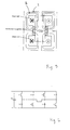
- the drive system 20 for a circuit breaker in accordance with the invention comprises an electromagnetic actuator 10, like the prior art actuator described with reference to figure 1 .
- the electromagnetic actuator 10 comprises a central cylindrical moving armature, in the following denoted plunger 12, permanent magnets 13, a closing coil 14, an opening coil 15 and a magnetic yoke 16, preferably made of iron.
- the electromagnetic actuator 10 is housed within a supporting structure 19.
- the electromagnetic actuator 10 also comprises a shaft 17 extending outside the supporting structure 19 to drive a mechanism (exemplary mechanism partly shown at reference numeral 18) for opening and closing the circuit breaker contacts (not shown).
- the circuit breaker may be any suitable one, for example a medium voltage vacuum circuit breaker.
- the magnetic fields of the coils 14, 15 when energized and the magnetic field of the permanent magnets 13 are indicated throughout the figures in a conventional manner.
- the drive system 20 further comprises an electronic drive circuit device, in the following denoted powering device 21 and illustrated schematically in figure 3 by a rectangle in dashed lines.
- the powering device 21 of the drive system 20 is, inter alia, used for switching the drive system 20 between its opening and closing positions. That is, for instance when a fault is detected and there is a need to trip the circuit breaker, the powering device 21 causes the drive system 20 to switch the circuit breaker to its open position.
- the circuit breaker may also be reset to assume its normal operation by switching the drive system 20 to its closing position, whereby the circuit breaker is switched to its closed position (i.e. reclosed after having been tripped).
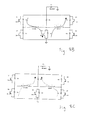
- FIG 4 A first embodiment of the powering device 21 suitable for use in the drive system 20 is illustrated in figure 4 .
- the opening coil 15 and the closing coil 14 are connected in anti-series.
- the schematic shown in figure 4 is a standard H-bridge driving the opening coil 15 and the closing coil 14 in anti series.
- the opening coil 15 is excited with a negative current.
- the magnetic flux from the permanent magnets 13 is thereby counter-balanced, or stated differently: the permanent magnets 13 are neutralized.
- the plunger 12 is thereby released from the magnetic locker that the permanent magnets 13 provide, before start of movement of the plunger 12.
- the movement of the plunger is then attracted by the other coil, in this case the closing coil 14.
- the closing coil 14 is excited with a negative current.
- the working coil is either the opening coil 15 or the closing coil 14 depending on the desired operation, i.e. the coil that attracts the plunger 12.
- Figure 5 illustrates the magnetic fields during the initialization of the closing operation.
- the magnetic flux induced by the opening coil 15 is illustrated by the outer field line (arrow I).
- the magnetic flux from the permanent magnets 13 is illustrated by the inner field line (arrow II), as well as the horizontal field lines. From the figure it is thus clear how the magnetic flux induced by the opening coil 15 counter-balances the magnetic flux from the permanent magnets 13.
- the invention has been described and illustrated in connection with a double-coil electromagnetic actuator 10. It is to be noted that the above-described powering device used for powering the actuator 10 may be used for powering a single-coil actuator as well. A circuit diagram illustrating this is shown in figure 6 . In a single coil actuator, the current is alternated in order to force the plunger 12 in different directions.
- separate circuits could be used for controlling the respective coils.
- a standard H-bridge could be used for controlling the opening coil 15 and another standard H-bridge could be used for controlling the closing coil 14. It is realized that twice the number of components would be required and thus twice the cost. However, in certain applications this solution could be advantageous, and in view of the lower energy consumption provided by the anti-series connected coils, separate circuits could still be economically justifiable.
- FIG. 7 Another embodiment of the powering device 21 suitable for use in the drive system 20 is illustrated in figure 7 .
- an additional power switch is added, as well as two free wheeling diodes.
- the added power switch allows overdriving the closing coil 14/opening coil 15 during closing operation/opening operation.
- Figures 8A-8C illustrate different phases for the closing operation.
- Figure 8A illustrates the start of the closing operation, the two coils 14, 15 being connected in anti-series.
- the power switches Z1 and Z4 are switched ON and the unbroken line indicate the current paths.
- the duration of this phase can be about 20 ms or until the current reaches about 30 A.
- the plunger 12 starts to move (downwards in figure 3 ).
- the induced voltage in the opening coil 15 is at its maximum.
- Figure 8B illustrates the second phase, when the closing coil is overdriving.
- the plunger 12 is released and has started moving.
- the whole dc-link voltage is applied across the working coil (i.e. the closing coil 14).
- the current will increase with significantly higher di/dt, which in turn results in a higher plunger speed, compared with the previous embodiment.
- the power switches Z1 and Z5 are switched ON and the unbroken line indicate the current paths. Again, in the figure, the dotted line indicates currents when the power switches are off.
- Figure 8C illustrates the final discharging of the closing coil 14. All the power switches are turned off and the dotted lines indicate the currents. The duration of this phase may be approximately 5 to 10 ms.
- the second embodiment of the powering device 21 is primarily suitable for a double-coil electromagnetic actuator.
- the second embodiment of the powering device 21 may speed up the plunger movement further and the rated currents for the power switches may possibly be reduced.
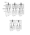
- FIGs 9A-9E illustrate the magnetic fields for different steps of the method in accordance with the invention.
- the interaction between the magnetic fluxes is illustrated for the first described embodiment of the powering device 21 (the "anti-series connection").
- the electromagnetic actuator 10 is in its open position and the permanent magnets 13 keep the plunger 12 (armature) at this first end position by the permanent magnetic flux.
- Figure 9B illustrates the case when a negative current energizes the opening coil 15 and a positive current energizes the closing coil 14. The opening coil 15 thereby provides a magnetic field counteracting the magnetic field provided by the permanent magnets 13.
- Figure 9C illustrates how the closing coil 14 starts to attract the plunger 12.
- Figure 9D illustrates the plunger 12 when it has reached about half way towards the closing position, wherein the closing position is the second end position of the plunger 12.
- Figure 9E finally, illustrates the plunger being in the second end position, i.e. the closing position. As shown, the permanent magnets 13 now hold the plunger 12 locked in the closed position.
- the opening coil 15 and the closing coil 14 are energized substantially simultaneously in order to move the plunger 12.
- the closing coil 14 or the opening coil 15 is fed with a negative current, whereby the permanent magnets 13 are neutralized by the coil being excited with the negative current.
- the other coil is fed with a current so as to move the plunger 12 towards one of its end positions.
- the permanent magnets 13 again hold it locked at the end position.
- the step of neutralizing the permanent magnets 13 may be initiated before the other coil, i.e. the working coil, is energized in order to attract the plunger.
- the working coil may be energized after a little while. They are however working in parallel for effectuating the movement of the plunger.
- the present invention provides an inventive arrangement and way of operating an electromagnetic actuator.
- only one of the coils of the actuator is used at a time; the closing coil is energized when a closing operation is to be performed and the opening coil is energized when the opening operation is to be performed.
- both coils are utilized in the opening operation as well as in the closing operation.
- a substantial energy saving is thereby accomplished, along with improved peak currents and faster response times of the moving armature of the actuator.
- the inventive drive system also enables significant cost saving for the actuator since the amount of iron can be reduced with up to 50%.
Landscapes
- Physics & Mathematics (AREA)
- Electromagnetism (AREA)
- Driving Mechanisms And Operating Circuits Of Arc-Extinguishing High-Tension Switches (AREA)
Abstract
The invention relates to a drive system 20 for a circuit breaker. The drive system comprises an electromagnetic actuator 10 having a first coil 14, a second coil 15, and an armature 12 arranged to be movable between a first and a second end position by means of the coils 14, 15. In accordance with the invention both coils 14, 15 are energized simultaneously for effectuating the movement of the armature 12 between the two end positions. This is in contrast to the prior art, wherein the coils are energized one at a time; one coil for moving the armature to one of the end positions and the other coil for moving the armature to the opposite end position.
Description
- The invention is related to the field of drive systems for operating circuit breakers. In particular, the invention is related to magnetic actuators used in actuation mechanisms of the circuit breakers.
- Protective relays are used throughout the electrical power distribution system for providing protection and control. The protective relays detect and isolate faults on transmission and distribution lines by opening and closing circuit breakers. Circuit breakers are thus an important part of power distribution systems and protect the electrical systems from damage caused by overload or short circuit. The circuit breaker is operated by a suitable drive system, which performs the opening and closing of the circuit breaker, and may, for example, be implemented by a magnetic actuator.
-
Figure 1 illustrates a state of the art linear magnetic actuator, suitable for operating a circuit breaker. Theactuator 1 comprises a central cylindrical movingarmature 2,permanent magnets 3, aclosing coil 4, anopening coil 5 and astator 6. Theactuator 1 also comprises ashaft 7 extending outside thestator 6 to drive a mechanism for opening and closing circuit breaker contacts. - In operation, the
armature 2 is held at the two ends of its stroke by a magnetic flux produced by thepermanent magnets 3; thepermanent magnets 3 thus provide a magnetic lock for keeping thearmature 2 at one of the end positions. In the figure, theelectromagnetic actuator 1 is held in an open position and an air gap 8 is present below thearmature 2 adjacent to theclosing coil 4. The associated circuit breaker contacts (not illustrated) are thereby held in an open position (tripped). In order to close the circuit breaker, theclosing coil 4 has to be energized. The magnetic flux produced by the current flowing through the coil windings of theclosing coil 4 is concentrated across the air gap 8 and thereby overcomes the force holding thearmature 2 in open position. This causes thearmature 2 to be driven over to the closed position. The opening operation is performed in a similar way by energizing theopening coil 5. -
Figures 2A, 2B and 2C illustrate the magnetic fields corresponding to the different positions. In particular,figure 2A illustrates the magnetic fields when themagnetic actuator 1 is in the open position and theclosing coil 4 has just been energized;figure 2B illustrates the magnetic field when the magnetic flux produced by the current flowing through the coil windings of theclosing coil 4 increases while the force holding thearmature 2 in open position is decreased; andfigure 2C illustrates the magnetic fields when thearmature 2 of themagnetic actuator 1 is driven to the closed position. - In the prior art solution, the actuator is thus pulled off of the permanent magnet lock. To be able to release the
armature 2 from the magnetic lock, the flux generated by theopening coil 5 must be made to exceed the permanent magnet flux. To overcome the permanent magnet flux substantial amounts of energy is required, which adds to the operation costs. Further, high peak currents may occur and this also adds to the costs, since rather expensive high rated components are required. - In view of the above, it would be desirable to provide an improved means for operating circuit breakers. In particular, the energy storage of the prior art drive systems represents approximately 20 % of their total cost and it would therefore be desirable to provide a more cost-efficient solution.
- It is an object of the invention to provide a drive system for circuit breakers providing less energy-consuming circuit breakers and a more energy-efficient operation of them.
- It is another object of the invention to provide a drive system for circuit breakers enabling faster response times of a moving armature of the drive system.
- It is yet another object of the invention to provide a drive system for circuit breakers enabling the use of lower rated components, to thereby lower the cost and size requirements.
- It is still another object of the invention to provide a drive system for circuit breakers having a lower overall size.
- It is yet another object of the invention to provide an improved method for operating circuit breakers, enabling energy savings and faster closing and opening operations of the circuit breakers.
- These objects, among others, are achieved by a drive system, by an electronic drive circuit, and by a method as claimed in the independent claims.
- In accordance with the invention a drive system for a circuit breaker is provided. The drive system comprises an electromagnetic actuator having a first coil, a second coil, and an armature arranged to be movable between a first and a second end position by means of the coils. In accordance with the invention both coils are energized simultaneously for effectuating the movement of the armature between the two end positions. This is in contrast to the prior art, wherein the coils are energized one at a time; one coil for moving the armature to one of the end positions and the other coil for moving the armature to the opposite end position. By means of the inventive drive system considerable energy savings can be obtained, providing cost savings and environmental advantages.
- In a preferred embodiment of the invention, the drive system further comprises permanent magnets for keeping the armature locked at the end positions. The drive system in accordance with the invention releases the actuator locker provided by the permanent magnets instead of pulling the actuator off of the locker as in the prior art. That is, the permanent magnet locker is neutralized to release the armature of the actuator. By means of this, huge energy savings can be made, approximately up to 60% energy reduction. Up to 80% lower peak currents are obtained, and the rated current for the power switches can be reduced. This in turn provides a less expensive manufacturing, since lower rated components can be used. Lower peak current also entails lower magnetic flux, which in turn enables a reduction of the physical size of the actuator. This also entails a cost saving of up to 50%. Further, the inventive drive system can be utilized in connection with different kinds of actuators. In particular, the inventive drive system enables the use of one common power electronic platform for both the conventional double coil actuator and the new developed single coil actuator.
- In accordance with another embodiment of the invention, the first and second coils are arranged in an anti-series connection. They may thus simultaneously be fed a negative and a positive current, respectively. This is a convenient and easily implemented way of accomplishing the simultaneous feeding thereby enabling the desired energy savings.
- In accordance with still another embodiment of the invention, the coils are arranged so that the magnetic field of one of the coils counteract the magnetic field of the permanent magnets while the magnetic field of the other coil attract the armature, thereby moving the armature to the opposite end position.
- Further embodiments of the invention are defined in the dependent claims.
- In accordance with a further aspect of the invention a method for powering a drive system for a circuit breaker is provided, whereby advantages similar to the above are achieved. In particular, by means of the method, a faster response of the moving armature of the drive system is provided as well as reduced energy consumption of the closing and opening operations of the circuit breakers.
- Further characteristics of the invention and advantages thereof will be evident from the detailed description of embodiments of the present invention given hereinafter and the accompanying figures, which are only given by way of illustration.
-
-
Figure 1 illustrates a state of the art magnetic actuator suitable for a medium voltage circuit breaker. -
Figures 2A, 2B and 2C illustrate the magnetic fields corresponding to the different positions of the magnetic actuator offigure 1 . -
Figure 3 illustrates a drive system in accordance with the invention, suitable for a circuit breaker. -
Figure 4 illustrates an exemplary powering device for use in the drive system in accordance with the invention. -
Figure 5 illustrates the magnetic fields during the initialization of the closing operation. -
Figure 6 illustrates the powering device offigure 4 connected to a single coil actuator. -
Figure 7 illustrates another exemplary powering device for use in the drive system in accordance with the invention. -
Figures 8A-8C illustrate different phases for the closing operation. -
Figures 9A-9E illustrate the magnetic fields for different steps of the method in accordance with the invention. - The present invention will now be described with reference first to
figure 3 . Only parts needed for the understanding of the present invention will be described, but it realized that other conventionally used parts, such as position sensors, energy storages, vacuum breakers etc., may be included. - The
drive system 20 for a circuit breaker in accordance with the invention comprises anelectromagnetic actuator 10, like the prior art actuator described with reference tofigure 1 . Theelectromagnetic actuator 10 comprises a central cylindrical moving armature, in the following denotedplunger 12,permanent magnets 13, a closing coil 14, an opening coil 15 and amagnetic yoke 16, preferably made of iron. Theelectromagnetic actuator 10 is housed within a supportingstructure 19. Theelectromagnetic actuator 10 also comprises ashaft 17 extending outside the supportingstructure 19 to drive a mechanism (exemplary mechanism partly shown at reference numeral 18) for opening and closing the circuit breaker contacts (not shown). The circuit breaker may be any suitable one, for example a medium voltage vacuum circuit breaker. - The magnetic fields of the coils 14, 15 when energized and the magnetic field of the
permanent magnets 13 are indicated throughout the figures in a conventional manner. - In accordance with the invention, the
drive system 20 further comprises an electronic drive circuit device, in the following denoted poweringdevice 21 and illustrated schematically infigure 3 by a rectangle in dashed lines. The poweringdevice 21 of thedrive system 20 is, inter alia, used for switching thedrive system 20 between its opening and closing positions. That is, for instance when a fault is detected and there is a need to trip the circuit breaker, the poweringdevice 21 causes thedrive system 20 to switch the circuit breaker to its open position. The circuit breaker may also be reset to assume its normal operation by switching thedrive system 20 to its closing position, whereby the circuit breaker is switched to its closed position (i.e. reclosed after having been tripped). - A first embodiment of the powering
device 21 suitable for use in thedrive system 20 is illustrated infigure 4 . In accordance with the invention, the opening coil 15 and the closing coil 14 are connected in anti-series. The schematic shown infigure 4 is a standard H-bridge driving the opening coil 15 and the closing coil 14 in anti series. For example, during a closing operation, i.e. when theplunger 12 should be moved downwards infigure 3 , the opening coil 15 is excited with a negative current. The magnetic flux from thepermanent magnets 13 is thereby counter-balanced, or stated differently: thepermanent magnets 13 are neutralized. Theplunger 12 is thereby released from the magnetic locker that thepermanent magnets 13 provide, before start of movement of theplunger 12. The movement of the plunger is then attracted by the other coil, in this case the closing coil 14. In a similar manner, during an opening operation the closing coil 14 is excited with a negative current. - By counter balancing (neutralizing) the
permanent magnet 13 flux, theplunger 12 is released and the required flux generated by the working coil is reduced. The working coil is either the opening coil 15 or the closing coil 14 depending on the desired operation, i.e. the coil that attracts theplunger 12. -
Figure 5 illustrates the magnetic fields during the initialization of the closing operation. The magnetic flux induced by the opening coil 15 is illustrated by the outer field line (arrow I). The magnetic flux from thepermanent magnets 13 is illustrated by the inner field line (arrow II), as well as the horizontal field lines. From the figure it is thus clear how the magnetic flux induced by the opening coil 15 counter-balances the magnetic flux from thepermanent magnets 13. - In the above embodiment, the invention has been described and illustrated in connection with a double-coil
electromagnetic actuator 10. It is to be noted that the above-described powering device used for powering theactuator 10 may be used for powering a single-coil actuator as well. A circuit diagram illustrating this is shown infigure 6 . In a single coil actuator, the current is alternated in order to force theplunger 12 in different directions. - Further, it is to be noted that separate circuits could be used for controlling the respective coils. For example, a standard H-bridge could be used for controlling the opening coil 15 and another standard H-bridge could be used for controlling the closing coil 14. It is realized that twice the number of components would be required and thus twice the cost. However, in certain applications this solution could be advantageous, and in view of the lower energy consumption provided by the anti-series connected coils, separate circuits could still be economically justifiable.
- Another embodiment of the powering
device 21 suitable for use in thedrive system 20 is illustrated infigure 7 . Compared to the above-described embodiment, an additional power switch is added, as well as two free wheeling diodes. The added power switch allows overdriving the closing coil 14/opening coil 15 during closing operation/opening operation. -
Figures 8A-8C illustrate different phases for the closing operation.Figure 8A illustrates the start of the closing operation, the two coils 14, 15 being connected in anti-series. The power switches Z1 and Z4 are switched ON and the unbroken line indicate the current paths. As an example, the duration of this phase can be about 20 ms or until the current reaches about 30 A. After this time, theplunger 12 starts to move (downwards infigure 3 ). The induced voltage in the opening coil 15 is at its maximum. -
Figure 8B illustrates the second phase, when the closing coil is overdriving. At this time, theplunger 12 is released and has started moving. By firing Z5 the whole dc-link voltage is applied across the working coil (i.e. the closing coil 14). The current will increase with significantly higher di/dt, which in turn results in a higher plunger speed, compared with the previous embodiment. The power switches Z1 and Z5 are switched ON and the unbroken line indicate the current paths. Again, in the figure, the dotted line indicates currents when the power switches are off. -
Figure 8C illustrates the final discharging of the closing coil 14. All the power switches are turned off and the dotted lines indicate the currents. The duration of this phase may be approximately 5 to 10 ms. - The second embodiment of the powering
device 21 is primarily suitable for a double-coil electromagnetic actuator. The second embodiment of the poweringdevice 21 may speed up the plunger movement further and the rated currents for the power switches may possibly be reduced. - The invention is also related to a method for operating an electromagnetic actuator, as described above, in turn suitable for operating a circuit breaker.
Figures 9A-9E illustrate the magnetic fields for different steps of the method in accordance with the invention. In particular, the interaction between the magnetic fluxes is illustrated for the first described embodiment of the powering device 21 (the "anti-series connection"). Infigure 9A , theelectromagnetic actuator 10 is in its open position and thepermanent magnets 13 keep the plunger 12 (armature) at this first end position by the permanent magnetic flux.Figure 9B illustrates the case when a negative current energizes the opening coil 15 and a positive current energizes the closing coil 14. The opening coil 15 thereby provides a magnetic field counteracting the magnetic field provided by thepermanent magnets 13. The locker provided by thepermanent magnets 13 is thereby neutralized.Figure 9C illustrates how the closing coil 14 starts to attract theplunger 12.Figure 9D illustrates theplunger 12 when it has reached about half way towards the closing position, wherein the closing position is the second end position of theplunger 12.
Figure 9E finally, illustrates the plunger being in the second end position, i.e. the closing position. As shown, thepermanent magnets 13 now hold theplunger 12 locked in the closed position. - In accordance with the method, the opening coil 15 and the closing coil 14 are energized substantially simultaneously in order to move the
plunger 12. In particular, the closing coil 14 or the opening coil 15 is fed with a negative current, whereby thepermanent magnets 13 are neutralized by the coil being excited with the negative current. At the same time, the other coil is fed with a current so as to move theplunger 12 towards one of its end positions. When theplunger 12 has stopped moving, thepermanent magnets 13 again hold it locked at the end position. - It is to be noted that if a solution comprising separate powering devices for controlling the respective coils is used, then the step of neutralizing the
permanent magnets 13 may be initiated before the other coil, i.e. the working coil, is energized in order to attract the plunger. The working coil may be energized after a little while. They are however working in parallel for effectuating the movement of the plunger. - In summary, the present invention provides an inventive arrangement and way of operating an electromagnetic actuator. In the prior art, only one of the coils of the actuator is used at a time; the closing coil is energized when a closing operation is to be performed and the opening coil is energized when the opening operation is to be performed. In accordance with the invention, both coils are utilized in the opening operation as well as in the closing operation. A substantial energy saving is thereby accomplished, along with improved peak currents and faster response times of the moving armature of the actuator. Further still, the inventive drive system also enables significant cost saving for the actuator since the amount of iron can be reduced with up to 50%.
Claims (16)
- A drive system (20) for a circuit breaker, the drive system (20) comprising an electromagnetic actuator (10) having a first coil (14), a second coil (15), and an armature (12) arranged to be movable between a first and a second end position by means of said first and second coils (14, 15), characterised in that said, first and second coils (14, 15) are arranged so as to be energized substantially simultaneously for accomplishing movements of said armature (12) between said first and second end positions.
- The drive system (20) as claimed in claim 1, wherein said electromagnetic actuator (10) further comprises permanent magnets (13) arranged to keep said armature (12) locked at said first and second end positions.
- The drive system (20) as claimed in claim 1 or 2, wherein said first and second coils (14, 15) are arranged in an anti-series connection.
- The drive system (20) as claimed in any of claims 1-3, wherein said first and second coils (14, 15) are fed a negative and a positive current, respectively.
- The drive system (20) as claimed in any of claims 2-4, wherein said coils (14, 15) are arranged so that the magnetic field of one of said first and second coils (14, 15) counteract the magnetic field of said permanent magnets (13) while the magnetic field of the other one of said first and second coils (14, 15) attract said armature (12).
- The drive system (20) as claimed in any of claims 1-5, wherein said second coil (15) is an opening coil arranged to move said armature (12) to an open position, said open position being said first end positions.
- The drive system (20) as claimed in any of claims 1-6, wherein said first coil (14) is a closing coil arranged to move said armature (12) to a close position, said close position being said second positions.
- The drive system (20) as claimed in any of claims 1-7, wherein said first and second coil (14, 15) are arranged at a respective end position of said armature (12).
- The drive system (20) as claimed in any of claims 1-8, further comprising an electronic drive circuit (21).
- The drive system (20) as claimed in claim 9, wherein said electronic drive circuit (21) is arranged to switch the drive system (20) between its first and second end positions.
- The drive system (20) as claimed in claim 9 or 10, wherein said electronic drive circuit (21) comprises an H-bridge.
- The drive system (20) as claimed in any of claims 1-8, further comprising two drive circuits, one circuit for controlling said first coil (14) and one circuit for controlling said second coil (15).
- An electronic drive circuit (21) for use in a drive system (20) as claimed in any of claims 1-11, characterized by means for connecting said first and second coils (14, 15) in an anti-series connection.
- A method for operating an electromagnetic actuator (10) for a circuit breaker, the electromagnetic actuator (10) comprising a first coil (14), a second coil (15), an armature (12) movable between a first and a second end positions by means of said first and second coils (14, 15), and permanent magnets (13) keeping said armature (12) locked at said first and second end positions, characterized by the step of:- energizing said first and second coils (14, 15) substantially simultaneously for moving said armature (12).
- The method as claimed in claim 14, said step of energizing comprising:- exciting said first coil (14) or said second coil (15) with a negative current, whereby said permanent magnets (13) are neutralized by the coil being excited with the negative current, and- exciting the other coil of said first and second coils (14, 15) with a current so as to move said armature (12) towards one of said end positions.
- The method as claimed in claim 15, wherein said steps of exciting said first and second coils (14, 15) are performed essentially simultaneously.
Priority Applications (3)
| Application Number | Priority Date | Filing Date | Title |
|---|---|---|---|
| EP07445013A EP1975960A1 (en) | 2007-03-30 | 2007-03-30 | A bistable magnetic actuator for circuit breakers with electronic drive circuit and method for operating said actuator |
| PCT/EP2008/053820 WO2008119786A1 (en) | 2007-03-30 | 2008-03-31 | A bistable magnetic actuator for circuit breakers with electronic drive circuit and method for operating said actuator |
| PCT/EP2008/053814 WO2008119785A1 (en) | 2007-03-30 | 2008-03-31 | A bistable magnetic actuator for circuit breakers with electronic drive circuit and method for operating said actuator |
Applications Claiming Priority (1)
| Application Number | Priority Date | Filing Date | Title |
|---|---|---|---|
| EP07445013A EP1975960A1 (en) | 2007-03-30 | 2007-03-30 | A bistable magnetic actuator for circuit breakers with electronic drive circuit and method for operating said actuator |
Publications (1)
| Publication Number | Publication Date |
|---|---|
| EP1975960A1 true EP1975960A1 (en) | 2008-10-01 |
Family
ID=38349605
Family Applications (1)
| Application Number | Title | Priority Date | Filing Date |
|---|---|---|---|
| EP07445013A Withdrawn EP1975960A1 (en) | 2007-03-30 | 2007-03-30 | A bistable magnetic actuator for circuit breakers with electronic drive circuit and method for operating said actuator |
Country Status (2)
| Country | Link |
|---|---|
| EP (1) | EP1975960A1 (en) |
| WO (2) | WO2008119786A1 (en) |
Cited By (7)
| Publication number | Priority date | Publication date | Assignee | Title |
|---|---|---|---|---|
| WO2010049234A1 (en) * | 2008-10-29 | 2010-05-06 | Zf Friedrichshafen Ag | Electromagnet |
| CN101867238A (en) * | 2010-06-28 | 2010-10-20 | 吉林省埃尔顿电气有限公司 | Integrated permanent magnet ring embedded self-positioning permanent magnet structure |
| EP2325858A1 (en) * | 2009-11-20 | 2011-05-25 | ABB Technology AG | Medium Voltage circuit breaker arrangement |
| US20150015347A1 (en) * | 2013-07-09 | 2015-01-15 | Schneider Electric Industries Sas | Device for detecting resetting of a circuit breaker, actuator of a separating mechanism of the circuit breaker contacts, electric circuit breaker and use of an induced current to generate a resetting indication signal |
| EP3032560B1 (en) | 2012-05-07 | 2017-04-05 | S & C Electric Co. | Bistable actuator device |
| WO2020093132A1 (en) * | 2018-11-05 | 2020-05-14 | HYDRO-QUéBEC | Bi-stable electromagnetic actuator |
| US11495380B2 (en) | 2017-02-01 | 2022-11-08 | Rhefor Gbr | Bistable hoisting solenoid |
Families Citing this family (6)
| Publication number | Priority date | Publication date | Assignee | Title |
|---|---|---|---|---|
| EP2330609B1 (en) * | 2009-12-04 | 2012-07-25 | ABB Technology AG | Magnetic actuator unit for a circuit-braker arrangement |
| DE102010041086A1 (en) | 2010-09-21 | 2012-03-22 | Zf Friedrichshafen Ag | Actuator device and method for driving |
| JP6422457B2 (en) * | 2016-03-04 | 2018-11-14 | 三菱電機株式会社 | Electromagnetic actuator and electromagnetic relay using the same |
| CN106531489B (en) * | 2016-11-25 | 2018-08-10 | 贵州泰永长征技术股份有限公司 | Dual-power transfer switch permanent magnetic drive structure is pressed in one kind |
| DE102017000907A1 (en) | 2017-02-01 | 2018-08-02 | Rhefor Gbr (Vertretungsberechtigter Gesellschafter: Arno Mecklenburg, 10999 Berlin) | Electromagnetic stopper for a general cargo conveyor |
| US11912253B2 (en) | 2020-03-10 | 2024-02-27 | Deere & Company | Symmetrically redundant solenoid valve for brake actuator and system thereof |
Citations (3)
| Publication number | Priority date | Publication date | Assignee | Title |
|---|---|---|---|---|
| EP0871192A2 (en) * | 1996-11-11 | 1998-10-14 | ABB Research Ltd. | Magnetic actuator |
| DE19929572A1 (en) * | 1999-06-22 | 2001-01-04 | Siemens Ag | Magnetic linear drive |
| US20040093718A1 (en) * | 2002-11-15 | 2004-05-20 | Mitsubishi Denki Kabushiki Kaisha | Actuator, method of manufacturing the actuator and circuit breaker provided with the actuator |
Family Cites Families (9)
| Publication number | Priority date | Publication date | Assignee | Title |
|---|---|---|---|---|
| CH426414A (en) * | 1965-08-27 | 1966-12-15 | Lucifer Sa | Electro-valve |
| US3814376A (en) * | 1972-08-09 | 1974-06-04 | Parker Hannifin Corp | Solenoid operated valve with magnetic latch |
| CN1003822B (en) * | 1984-10-09 | 1989-04-05 | 三菱矿业水泥株式会社 | Electromagnetic actuator |
| US4533890A (en) * | 1984-12-24 | 1985-08-06 | General Motors Corporation | Permanent magnet bistable solenoid actuator |
| US4690371A (en) * | 1985-10-22 | 1987-09-01 | Innovus | Electromagnetic valve with permanent magnet armature |
| DE59309583D1 (en) * | 1992-03-31 | 1999-06-24 | Ellenberger & Poensgen | Remote controllable circuit breaker |
| GB2299896B (en) * | 1995-04-11 | 2000-03-08 | Mckean Brian Ass Ltd | Improvements in and relating to permanent magnet bistable actuators |
| US20020153982A1 (en) * | 2001-04-19 | 2002-10-24 | R. Audemars Sa | Electromagnetic actuator |
| JP4192645B2 (en) * | 2003-03-24 | 2008-12-10 | 三菱電機株式会社 | Operation circuit and power switchgear using the same |
-
2007
- 2007-03-30 EP EP07445013A patent/EP1975960A1/en not_active Withdrawn
-
2008
- 2008-03-31 WO PCT/EP2008/053820 patent/WO2008119786A1/en not_active Ceased
- 2008-03-31 WO PCT/EP2008/053814 patent/WO2008119785A1/en not_active Ceased
Patent Citations (3)
| Publication number | Priority date | Publication date | Assignee | Title |
|---|---|---|---|---|
| EP0871192A2 (en) * | 1996-11-11 | 1998-10-14 | ABB Research Ltd. | Magnetic actuator |
| DE19929572A1 (en) * | 1999-06-22 | 2001-01-04 | Siemens Ag | Magnetic linear drive |
| US20040093718A1 (en) * | 2002-11-15 | 2004-05-20 | Mitsubishi Denki Kabushiki Kaisha | Actuator, method of manufacturing the actuator and circuit breaker provided with the actuator |
Cited By (15)
| Publication number | Priority date | Publication date | Assignee | Title |
|---|---|---|---|---|
| WO2010049234A1 (en) * | 2008-10-29 | 2010-05-06 | Zf Friedrichshafen Ag | Electromagnet |
| US8629366B2 (en) | 2009-11-20 | 2014-01-14 | Abb Technology Ag | Medium voltage circuit breaker arrangement |
| WO2011060921A1 (en) * | 2009-11-20 | 2011-05-26 | Abb Technology Ag | Medium voltage circuit breaker arrangement |
| CN102687228A (en) * | 2009-11-20 | 2012-09-19 | Abb技术股份公司 | Medium voltage circuit breaker arrangement |
| EP2325858A1 (en) * | 2009-11-20 | 2011-05-25 | ABB Technology AG | Medium Voltage circuit breaker arrangement |
| CN101867238B (en) * | 2010-06-28 | 2012-04-18 | 吉林省埃尔顿电气有限公司 | Self-positioning permanent magnet structure embedded with integrated permanent magnet ring |
| CN101867238A (en) * | 2010-06-28 | 2010-10-20 | 吉林省埃尔顿电气有限公司 | Integrated permanent magnet ring embedded self-positioning permanent magnet structure |
| EP3032560B1 (en) | 2012-05-07 | 2017-04-05 | S & C Electric Co. | Bistable actuator device |
| EP3032560B2 (en) † | 2012-05-07 | 2023-03-01 | S & C Electric Co. | Bistable actuator device |
| US9245697B2 (en) * | 2013-07-09 | 2016-01-26 | Schneider Electric Industries Sas | Device for detecting resetting of a circuit breaker, actuator of a separating mechanism of the circuit breaker contacts, electric circuit breaker and use of an induced current to generate a resetting indication signal |
| US20150015347A1 (en) * | 2013-07-09 | 2015-01-15 | Schneider Electric Industries Sas | Device for detecting resetting of a circuit breaker, actuator of a separating mechanism of the circuit breaker contacts, electric circuit breaker and use of an induced current to generate a resetting indication signal |
| US11495380B2 (en) | 2017-02-01 | 2022-11-08 | Rhefor Gbr | Bistable hoisting solenoid |
| EP3566240B1 (en) * | 2017-02-01 | 2024-08-07 | Rhefor GbR | Bistable hoisting solenoid |
| WO2020093132A1 (en) * | 2018-11-05 | 2020-05-14 | HYDRO-QUéBEC | Bi-stable electromagnetic actuator |
| US12094674B2 (en) | 2018-11-05 | 2024-09-17 | HYDRO-QUéBEC | Bi-stable electromagnetic actuator |
Also Published As
| Publication number | Publication date |
|---|---|
| WO2008119786A1 (en) | 2008-10-09 |
| WO2008119785A1 (en) | 2008-10-09 |
Similar Documents
| Publication | Publication Date | Title |
|---|---|---|
| EP1975960A1 (en) | A bistable magnetic actuator for circuit breakers with electronic drive circuit and method for operating said actuator | |
| US6611413B2 (en) | Switching apparatus | |
| KR101044423B1 (en) | Circuit breaker and its opening and closing method | |
| US6674349B1 (en) | Opening and/or closing control device, in particular for a switchgear apparatus such as a circuit breaker, and circuit breaker equipped with such a device | |
| US20100165535A1 (en) | Method and Device for Operating a Switching Device | |
| US20090244801A1 (en) | Operative control circuit of multiple electromagnetic actuating devices in series and parallel connection | |
| EP2551881B1 (en) | Actuator for a circuit breaker | |
| JP5295858B2 (en) | Electromagnetic actuator, electromagnetically operated switchgear using the same, and control method thereof | |
| KR101449736B1 (en) | Bypass apparatus for converter | |
| EA026040B1 (en) | Method and apparatus for controlling circuit breaker operation | |
| EP3549149B1 (en) | Contactor with coil polarity reversing control circuit | |
| EP2197011A1 (en) | Drive system for operating an electric device | |
| JP5606304B2 (en) | Electromagnetic operation device and drive circuit for switchgear | |
| KR101599234B1 (en) | Modular multilevel converter bypass switching device and method | |
| SE518322C2 (en) | Electric switch, as well as plant, use and procedure where such is utilized | |
| JP2006236773A (en) | Circuit breaker | |
| JP2004152628A (en) | Electromagnet control device | |
| US7663457B2 (en) | Magnetic latch for a voice coil actuator | |
| US11621134B1 (en) | High speed solenoid driver circuit | |
| JP2016103331A (en) | Switch and power conversion device | |
| US7352265B2 (en) | Manual trip control method and arrangement for multiple circuit interrupters | |
| WO2025119930A1 (en) | Bistable electromagnetic switching device | |
| JP4592365B2 (en) | Vacuum shut-off device control circuit | |
| EP1821400A1 (en) | A system for providing three-phase current to an electric motor | |
| WO2008150287A1 (en) | Magnetic latch for a voice coil actuator |
Legal Events
| Date | Code | Title | Description |
|---|---|---|---|
| PUAI | Public reference made under article 153(3) epc to a published international application that has entered the european phase |
Free format text: ORIGINAL CODE: 0009012 |
|
| AK | Designated contracting states |
Kind code of ref document: A1 Designated state(s): AT BE BG CH CY CZ DE DK EE ES FI FR GB GR HU IE IS IT LI LT LU LV MC MT NL PL PT RO SE SI SK TR |
|
| AX | Request for extension of the european patent |
Extension state: AL BA HR MK RS |
|
| AKX | Designation fees paid | ||
| REG | Reference to a national code |
Ref country code: DE Ref legal event code: 8566 |
|
| STAA | Information on the status of an ep patent application or granted ep patent |
Free format text: STATUS: THE APPLICATION HAS BEEN WITHDRAWN |
|
| 18W | Application withdrawn |
Effective date: 20090817 |