EP1975754A1 - A computer implemented method to display technical data for monitoring an industrial installation - Google Patents
A computer implemented method to display technical data for monitoring an industrial installation Download PDFInfo
- Publication number
- EP1975754A1 EP1975754A1 EP07105413A EP07105413A EP1975754A1 EP 1975754 A1 EP1975754 A1 EP 1975754A1 EP 07105413 A EP07105413 A EP 07105413A EP 07105413 A EP07105413 A EP 07105413A EP 1975754 A1 EP1975754 A1 EP 1975754A1
- Authority
- EP
- European Patent Office
- Prior art keywords
- points
- holographic image
- industrial installation
- industrial
- display
- Prior art date
- Legal status (The legal status is an assumption and is not a legal conclusion. Google has not performed a legal analysis and makes no representation as to the accuracy of the status listed.)
- Granted
Links
Images


Classifications
-
- G—PHYSICS
- G05—CONTROLLING; REGULATING
- G05B—CONTROL OR REGULATING SYSTEMS IN GENERAL; FUNCTIONAL ELEMENTS OF SUCH SYSTEMS; MONITORING OR TESTING ARRANGEMENTS FOR SUCH SYSTEMS OR ELEMENTS
- G05B23/00—Testing or monitoring of control systems or parts thereof
- G05B23/02—Electric testing or monitoring
- G05B23/0205—Electric testing or monitoring by means of a monitoring system capable of detecting and responding to faults
- G05B23/0259—Electric testing or monitoring by means of a monitoring system capable of detecting and responding to faults characterized by the response to fault detection
- G05B23/0267—Fault communication, e.g. human machine interface [HMI]
Definitions
- the invention concerns methods and systems for remote monitoring of process equipment and process objects in an industrial control system.
- the invention relates to monitoring of processes in oil and gas installations, production platforms and processing facilities.
- IT In the field of process control in industrial plants IT is used as a strategic tool to make work tasks and decision processes more efficient. For example in the extended oil and gas sector, an extensive reallocation of work tasks between sea and land and between operators and suppliers is underway. The result includes new work processes where personnel, often in different locations, interact using IT and live data integrated in the work processes.
- Use of IT creates opportunities in control, monitoring and maintenance in the form of new advanced functions.
- a greater degree of automation of functions currently handled manually, i.e. data collation, report generation, planning, initiation, notification and coordination of tasks is developing.
- desktop computer screens which limit the user to interact with the system in 2D, using keyboard, mouse or similar to browse through a series of process pictures and related data.
- desktop screens also limits the numbers of users and therefore hinders collaboration possibilities between local and/or remote users.
- an improvement is provided in the form of an improved method to generate a display of an industrial installation or part thereof including dynamic information about an event or an alarm, location of personnel, an/or position of a process equipment which method comprises displaying a holographic image comprising a view of said industrial installation, which said view comprises one or more points in three dimensional space and which point or points are each mapped to a corresponding point or position in said industrial installation.
- an improvement is provided in the form of an improved method to generate a display of an oil and gas production platform or part thereof including dynamic information about an event or an alarm, location of personnel, an/or position of a process equipment, which method comprises displaying a holographic image comprising a view of said oil and gas production platform installation, which said view comprises one or more points in three dimensional space and which point or points are each mapped to a corresponding point or position in said oil and gas production platform.
- an improvement is provided in the form of an improved method to generate a holographic image of an industrial installation or part thereof including information about an event or an alarm, comprising the step of placing a pointer object near to one of the one or more points in the holographic image and identifying the one of the one or more points which has been selected.
- an improvement is provided in the form of an improved method to generate a holographic image of an industrial installation or part thereof including information about an event or an alarm, comprising the step of mapping the one of the one or more points which has been identified to an equipment, process section or part thereof in said industrial installation.
- an improvement is provided in the form of an improved method to generate a holographic image of an industrial installation or part thereof including information about an event or an alarm comprising the step of mapping the one of the one or more points which has been identified to one or more personnel located at an equipment, process section or part thereof in said industrial installation.
- This embodiment has the advantage of quickly and efficiently showing whereabouts on an oil platform or in another industrial installation an operator or engineer is located, which facilitates locating and/or treating or evacuating an operator in a problem situation.
- the focus of this invention is to present large amounts of process information using holographic images which provide the users with a 3D view of the site.
- 3D visualization the users get an improved view of the situation and current state of the site.
- the users can quickly locate all reported events occurring to their respective positions in the platform or installation and access the system to retrieve further information, using a dedicated input device.
- the users may also select information regarding other objects of interest, such as position and identity of personnel and similar to retrieve more detailed information.
- the holographic system is used for monitoring and surveillance, and is not directed towards direct control of the site.
- a typical use is in an onshore operations or support or control room which houses internal experts (e.g. process planners, process engineers, management etc.) and third-party experts.
- the invention presents information about an installation comprising many complex processes in a clear and intuitive way, and methods providing access to or interaction with this information.
- the invention describes:
- An advantage is the generation of an improved overview of a current state of a given site and a 3-D interface through which to quickly retrieve more detailed information on selected events or objects.
- the invention allows an unlimited number of viewers to collaborate around the same hologram. This creates a working environment in which all users have the same hologram no matter location, and with different expertise.
- Another advantage is the provision of position information for optimising or increasing production, by improved access to monitoring information and for real-time interaction between involved activities and disciplines, e.g. by users monitoring compressors or wells from land, and by contact with users or experts in the field if matters requiring action are discovered.
- the use of the invention is advantageous for eg interaction rooms used to support work processes between land and sea and between operator and supplier. This is in part because the invention provides an interface that promotes improved user perception of the site, the layout of relevant equipment or sections and the current state. It also supports efficient collaboration, both local and remote.
- the operations for which the invention may be applied may also comprise so includes drilling, operations and maintenance or upgrades.
- the invention is adapted for use eg for continuous monitoring and/or support from onshore specialists, both own and suppliers' on a 24-hour basis.
- the monitoring may also be applied to planning of scheduled operations and s well as planning or guidance for unplanned or critical situations.
- a remote expert can see from the holographic image which operator is located closest to a relevant equipment, and guide the operator by eg phone or SMS or computer link to carry out an observation or carrying out a procedure to change a set-point or the like.
- a further advantage is reduced operating and maintenance costs at the industrial installation which may be located, as in the case of an oil platform, such that it is time consuming, difficult or dangerous to access, by, with the aid of an embodiment of the invention enabling:
- an improvement is provided in the form of an improved system for monitoring an industrial installation arranged with computer program means to generate a display of said industrial installation or part thereof including information about an event or an alarm, and a computer, further comprising means for generating a display of a holographic image comprising a view of said industrial installation which said view comprises one or more points in three dimensional space and which point or points are each mapped to a corresponding point or position in said industrial installation.
- an improvement is provided in the form of an improved system for monitoring for an industrial installation comprising means for generating a display of a holographic image comprising a view of said industrial installation further comprising means for determining that a pointer object has been placed near to the one of the one or more points in the holographic image and means for identifying the one of the one or more points which as been selected.
- an improvement is provided in the form of an improved system for monitoring for an oil and gas production platform, the system comprising means for generating a display of a holographic image comprising a view of said oil platform further comprising optical registration means for determining that a pointer object has been placed near to the one of the one or more points in the holographic image and means for identifying the one of the one or more points which as been selected.
- an improvement is provided in the form of an improved system for monitoring for an industrial installation comprising means for generating a display of a holographic image comprising a view of said industrial installation comprising computer program means for mapping the one of the one or more points which has been identified to a process section or part thereof in said industrial installation.
- one or more methods may be carried out by a computing device comprising one or more microprocessor units or computers.
- the control unit(s) comprises memory means for storing one or more computer programs for carrying out the improved methods.
- Preferably such computer program contains instructions for the processor to perform the method as mentioned above and described in more detail below.
- Figure 1 shows an exemplary example of an embodiment of the invention.
- the figure shows a holographic system 3 for producing holographic images, and a holographic display 1 of an oil production platform.
- a pointer device 2 is shown positioned for interaction with the holographic image 1.
- the pointer 2 is shown here connected by a wire or wirelessly to a computer 8 which is also connected to the holographic system 3.
- a separate display, an external graphic screen 11 is schematically positioned adjacent the holographic image 1.
- the system for carrying out the method comprises then a holographic apparatus 3 which generates an holographic image 1, and the device may also comprise light refraction detectors (not shown) or other means which may register where on the holographic image 1 the user "touches", and an input device 2 with which the user may interact with the holographic image and preferably a data server which constantly feeds the holographic apparatus with updated process information.
- An oil production platform or another industrial installation is arranged with an industrial control system.
- the control system may provide information about a problem of some sort with a given control valve.
- the problem with the control valve is indicated, eg with the color red marking the position of the control valve in the 3-D image of the holographic image 1.
- the holographic image displays the relative location of the control valve with the red mark or a flashing red point of light. Clicking on the valve with the input/pointing device results in the control system displaying further information about the control valve and/or event. Further information may, for example, be displayed on an external display such as display 11 of Fig 1 .
- the user is provided with more information about the relative plant location of the problem valve with immediate access to event information and/or object information accessed from or generated by the control system.
- the local or remote user receives then an improved delivery of information on which to base further actions.
- Health and security of personnel on an oil platform or in other potentially dangerous industrial installations is a very important issue.
- OHSE Occupational health and Safety
- the hologram will show the location of the injured person and by selecting the object in the hologram, the user will get access to important medical information, such as name, age, gender, blood type, allergies, etc supplied to the display or external display 11 from the control system of the installation.
- the output from such examples can be displayed as an overlaying hologram or on an external screen 11.
- the external screen may be part of the hologram apparatus or a separate device.
- the holographic apparatus comprises a light beam generator (typically a laser) which renders the holographic images.
- the apparatus is also arranged with a light beam detector which detects light beams refracted, reflected or scattered by the tip of the input device 2, which may be an active tip.
- the detector may for example register the intensity, and thus the length, of the refracted beam. It also registers the x,y-position of the same light beam.
- a computing device then calculates the spatial position of the "touched" point based on length of the refracted light beam (z-position) and the refracted light beam's x,y-position.
- the pointer device may include a haptic actuator which gives the user haptic feedback when the user "touches" specific targets, events, objects or similar in the holographic image.
- the haptic actuator is triggered by input from the light beam detector which continuously registers the "touched” points.
- This screen may be part of the holographic image or a separate device.
- a computer system which is connected to the holographic system, including the hologram apparatus, and which continuously feeds the holographic system with status information on the site (plant, oil platform or similar).
- the computer system comprises the following;
- one or more remote experts can see from the holographic image which operator is located closest to a relevant equipment.
- the expert or experts may then discuss an event or alarm, and may guide the operator by eg phone or SMS or computer link in carrying out an observation or carrying out a procedure to change check a setting, check or adjust a set-point or the like.
- the system can be configured in different ways.
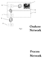
- Figure 2 shows an architecture comprising an embodiment of the invention.
- the figure shows a holographic image 1 of an oil production platform, connected to an onshore network 15.
- the onshore network is connected via secure data communication arrangements to a process network 7.
- the process network is further connected to one or more computers 8 and a control network 9, or process control network, which controls the oil platform or other industrial installation.
- the onshore network 16 comprising the holographic image may be established within a relatively low security arrangement. This is in comparison with the data communication and process control arrangements 17 for an oil platform or other industrial installation which requires highly secure data and computing networks.
- Figure 3 shows another architecture comprising an embodiment of the invention. It shows the holographic image 1 generated by holographic device 3 and pointer 2 of Fig 1 .
- a leakage problem with a control valve 12 connected via an I/O module or node 14 to the process network 7 results in an alarm in a control system.
- the control system is also connected to data storage containing data on equipment, processes and process history of the oil platform or industrial installation.
- the position in the installation of the object associated with the alarm or event reported in the control system may be mapped to a 3-D model, the position in 3-D space calculated for the position of that event or alarm object, control valve 12 in this example, in the 3-D model, and the corresponding position then shown marked on the holographic image 1.
- a coloured light or flashing light or similar For example as a coloured light or flashing light or similar. In this way the location of an object which is the subject of an event or alarm reported in the control system is shown in its 3-D position in space on the holographic image.
- Methods of the invention may be supervised, controlled or carried out by one or more computer programs.
- One or more microprocessors or processors or computers
- CPU central processing unit
- processors or computers comprise a central processing unit CPU connected to or comprised in one or more of the above computers or computer systems, which processors or computers perform the steps of the methods according to one or more aspects of the invention, as described for example in reference to the Figures.
- the computer programs for carrying out methods according to the invention may also be run on one or more general purpose industrial microprocessors or PLCs or computers instead of one or more specially adapted computers or processors.
- the computer program comprises computer program code elements or software code portions that make the computer or processor perform the methods using equations, algorithms, data, stored values, calculations, synchronisations and the like for the methods previously described.
- a part of the program may be stored in a processor as above, but also in a ROM, RAM, PROM, EPROM or EEPROM chip or similar memory means.
- the or some of the programs in part or in whole may also be stored locally (or centrally) on, or in, other suitable computer readable medium such as a magnetic disk, CD-ROM or DVD disk, hard disk, magneto-optical memory storage means, in volatile memory, in flash memory, as firmware, or stored on a data server.
- the program may also in part be supplied or updated from a data network, including a public network such as the Internet.
Abstract
Description
- The invention concerns methods and systems for remote monitoring of process equipment and process objects in an industrial control system. In particular the invention relates to monitoring of processes in oil and gas installations, production platforms and processing facilities.
- Today, most industrial installations and production facilities have modern and effective systems for data acquisition and storage with eg fiber-optic communications, databases, and so on. A problem is that users are often not able to extract all the information that is hidden in the acquired data, because in part, the amount of process data is enormous. Even though historical data is easily available, the user may need assistance help to locate process segments behaving abnormally, to gather information about that, and to arrive at a diagnosis of a condition or status of a process or equipment.
- In the field of process control in industrial plants IT is used as a strategic tool to make work tasks and decision processes more efficient. For example in the extended oil and gas sector, an extensive reallocation of work tasks between sea and land and between operators and suppliers is underway. The result includes new work processes where personnel, often in different locations, interact using IT and live data integrated in the work processes. Use of IT creates opportunities in control, monitoring and maintenance in the form of new advanced functions. A greater degree of automation of functions currently handled manually, i.e. data collation, report generation, planning, initiation, notification and coordination of tasks is developing.
- Common ways of presenting data is mostly done using desktop computer screens, which limit the user to interact with the system in 2D, using keyboard, mouse or similar to browse through a series of process pictures and related data. Use of desktop screens also limits the numbers of users and therefore hinders collaboration possibilities between local and/or remote users.
- According to an aspect of the present invention an improvement is provided in the form of an improved method to generate a display of an industrial installation or part thereof including dynamic information about an event or an alarm, location of personnel, an/or position of a process equipment which method comprises displaying a holographic image comprising a view of said industrial installation, which said view comprises one or more points in three dimensional space and which point or points are each mapped to a corresponding point or position in said industrial installation.
- According to an embodiment of the present invention an improvement is provided in the form of an improved method to generate a display of an oil and gas production platform or part thereof including dynamic information about an event or an alarm, location of personnel, an/or position of a process equipment, which method comprises displaying a holographic image comprising a view of said oil and gas production platform installation, which said view comprises one or more points in three dimensional space and which point or points are each mapped to a corresponding point or position in said oil and gas production platform.
- According to another embodiment of the present invention an improvement is provided in the form of an improved method to generate a holographic image of an industrial installation or part thereof including information about an event or an alarm, comprising the step of placing a pointer object near to one of the one or more points in the holographic image and identifying the one of the one or more points which has been selected.
- According to another embodiment of the present invention an improvement is provided in the form of an improved method to generate a holographic image of an industrial installation or part thereof including information about an event or an alarm, comprising the step of mapping the one of the one or more points which has been identified to an equipment, process section or part thereof in said industrial installation.
- According to another embodiment of the present invention an improvement is provided in the form of an improved method to generate a holographic image of an industrial installation or part thereof including information about an event or an alarm comprising the step of mapping the one of the one or more points which has been identified to one or more personnel located at an equipment, process section or part thereof in said industrial installation. This embodiment has the advantage of quickly and efficiently showing whereabouts on an oil platform or in another industrial installation an operator or engineer is located, which facilitates locating and/or treating or evacuating an operator in a problem situation.
- The focus of this invention is to present large amounts of process information using holographic images which provide the users with a 3D view of the site. Through the 3D visualization the users get an improved view of the situation and current state of the site. The users can quickly locate all reported events occurring to their respective positions in the platform or installation and access the system to retrieve further information, using a dedicated input device. The users may also select information regarding other objects of interest, such as position and identity of personnel and similar to retrieve more detailed information. The holographic system is used for monitoring and surveillance, and is not directed towards direct control of the site. A typical use is in an onshore operations or support or control room which houses internal experts (e.g. process planners, process engineers, management etc.) and third-party experts.
- The invention presents information about an installation comprising many complex processes in a clear and intuitive way, and methods providing access to or interaction with this information. The invention describes:
- presentation of large amounts of process information using holographic images to create a 3D view of the site,
- a device for interacting with the holographic image,
- navigation in the 3D view of the plant or platform and information retrieval
- communication between the underlying control system and the holographic apparatus generating the holographic images
- An advantage is the generation of an improved overview of a current state of a given site and a 3-D interface through which to quickly retrieve more detailed information on selected events or objects. The invention allows an unlimited number of viewers to collaborate around the same hologram. This creates a working environment in which all users have the same hologram no matter location, and with different expertise.
- Another advantage is the provision of position information for optimising or increasing production, by improved access to monitoring information and for real-time interaction between involved activities and disciplines, e.g. by users monitoring compressors or wells from land, and by contact with users or experts in the field if matters requiring action are discovered. The use of the invention is advantageous for eg interaction rooms used to support work processes between land and sea and between operator and supplier. This is in part because the invention provides an interface that promotes improved user perception of the site, the layout of relevant equipment or sections and the current state. It also supports efficient collaboration, both local and remote.
- The operations for which the invention may be applied may also comprise so includes drilling, operations and maintenance or upgrades. Advantageously the invention is adapted for use eg for continuous monitoring and/or support from onshore specialists, both own and suppliers' on a 24-hour basis. The monitoring may also be applied to planning of scheduled operations and s well as planning or guidance for unplanned or critical situations. Thus, for example, a remote expert can see from the holographic image which operator is located closest to a relevant equipment, and guide the operator by eg phone or SMS or computer link to carry out an observation or carrying out a procedure to change a set-point or the like.
- A further advantage is reduced operating and maintenance costs at the industrial installation which may be located, as in the case of an oil platform, such that it is time consuming, difficult or dangerous to access, by, with the aid of an embodiment of the invention enabling:
- Condition- and campaign-based maintenance
- Transferal of administrative, surveillance, management and reviewing activities onshore
- Reduced usage of experts offshore
- Onshore remote monitoring
- Improved efficiency for monitoring and analysis functions
- New ways of supporting the fields by centralising tasks, cross-field coordination and specialising service supplies to a larger degree
- According to an aspect of the present invention an improvement is provided in the form of an improved system for monitoring an industrial installation arranged with computer program means to generate a display of said industrial installation or part thereof including information about an event or an alarm, and a computer, further comprising means for generating a display of a holographic image comprising a view of said industrial installation which said view comprises one or more points in three dimensional space and which point or points are each mapped to a corresponding point or position in said industrial installation.
- According to another embodiment of the present invention an improvement is provided in the form of an improved system for monitoring for an industrial installation comprising means for generating a display of a holographic image comprising a view of said industrial installation further comprising means for determining that a pointer object has been placed near to the one of the one or more points in the holographic image and means for identifying the one of the one or more points which as been selected.
- According to another embodiment of the present invention an improvement is provided in the form of an improved system for monitoring for an oil and gas production platform, the system comprising means for generating a display of a holographic image comprising a view of said oil platform further comprising optical registration means for determining that a pointer object has been placed near to the one of the one or more points in the holographic image and means for identifying the one of the one or more points which as been selected.
- According to another embodiment of the present invention an improvement is provided in the form of an improved system for monitoring for an industrial installation comprising means for generating a display of a holographic image comprising a view of said industrial installation comprising computer program means for mapping the one of the one or more points which has been identified to a process section or part thereof in said industrial installation.
- In a preferred embodiment of the methods of the invention one or more methods may be carried out by a computing device comprising one or more microprocessor units or computers. The control unit(s) comprises memory means for storing one or more computer programs for carrying out the improved methods. Preferably such computer program contains instructions for the processor to perform the method as mentioned above and described in more detail below.
- Embodiments of the invention will now be described, by way of example only, with particular reference to the accompanying drawings in which:
-
FIGURE 1 is a schematic diagram of a holographic user interface for generated and displaying a 3-D view of an oil platform or an industrial installation according to an embodiment of the invention, -
FIGURE 2 is a block diagram of the architecture of an embodiment of the invention, -
FIGURE 3 is a block diagram of an architecture for a method and system according to an embodiment of the invention. -
Figure 1 shows an exemplary example of an embodiment of the invention. The figure shows aholographic system 3 for producing holographic images, and aholographic display 1 of an oil production platform. Apointer device 2 is shown positioned for interaction with theholographic image 1. Thepointer 2 is shown here connected by a wire or wirelessly to acomputer 8 which is also connected to theholographic system 3. A separate display, an externalgraphic screen 11 is schematically positioned adjacent theholographic image 1. - The system for carrying out the method comprises then a
holographic apparatus 3 which generates anholographic image 1, and the device may also comprise light refraction detectors (not shown) or other means which may register where on theholographic image 1 the user "touches", and aninput device 2 with which the user may interact with the holographic image and preferably a data server which constantly feeds the holographic apparatus with updated process information. - An oil production platform or another industrial installation is arranged with an industrial control system. As an illustrative example the control system may provide information about a problem of some sort with a given control valve. The problem with the control valve is indicated, eg with the color red marking the position of the control valve in the 3-D image of the
holographic image 1. The holographic image displays the relative location of the control valve with the red mark or a flashing red point of light. Clicking on the valve with the input/pointing device results in the control system displaying further information about the control valve and/or event. Further information may, for example, be displayed on an external display such asdisplay 11 ofFig 1 . Thus the user is provided with more information about the relative plant location of the problem valve with immediate access to event information and/or object information accessed from or generated by the control system. The local or remote user receives then an improved delivery of information on which to base further actions. - Health and security of personnel on an oil platform or in other potentially dangerous industrial installations is a very important issue. For OHSE (Occupational health and Safety) purposes and in the unlikely event of a personnel injuring himself and falling into an unconscious state somewhere in the platform or plant, the hologram will show the location of the injured person and by selecting the object in the hologram, the user will get access to important medical information, such as name, age, gender, blood type, allergies, etc supplied to the display or
external display 11 from the control system of the installation. - The output from such examples can be displayed as an overlaying hologram or on an
external screen 11. The external screen may be part of the hologram apparatus or a separate device. The benefit of using a 3D visualization of objects in relation to injured personnel or personnel at risk is that it provides a fast way to gather information to identify the location of the person, and to investigate the corresponding necessary assessment and routing of maintenance and emergency personnel to the person and/or to an exit or vehicle access point etc.. - The holographic apparatus comprises a light beam generator (typically a laser) which renders the holographic images. The apparatus is also arranged with a light beam detector which detects light beams refracted, reflected or scattered by the tip of the
input device 2, which may be an active tip. The detector may for example register the intensity, and thus the length, of the refracted beam. It also registers the x,y-position of the same light beam. A computing device then calculates the spatial position of the "touched" point based on length of the refracted light beam (z-position) and the refracted light beam's x,y-position. - A pointer or an
input device 2 connected to the hologram apparatus (wired or wirelessly) to enable manipulation of the hologram (navigation, selection of icons, objects etc.), preferably comprises: a physical pointer device with a wired or wireless connection to the hologram apparatus, a tip or an active tip of the pointer arranged such that it is the only registrable point for the above light beam detector, a control such as a button, scroll wheel or similar on the said device which activates the said beam detector in the hologram apparatus. Hence, the user clicks/turns/scrolls the said control to select the "touched" point. Optionally the pointer device may include a haptic actuator which gives the user haptic feedback when the user "touches" specific targets, events, objects or similar in the holographic image. The haptic actuator is triggered by input from the light beam detector which continuously registers the "touched" points. - An
external screen 11 on which detail information on selected targets, events, objects or similar can be displayed. This screen may be part of the holographic image or a separate device. A computer system which is connected to the holographic system, including the hologram apparatus, and which continuously feeds the holographic system with status information on the site (plant, oil platform or similar). The computer system comprises the following; - a connection to one or more remote servers that allow access to centrally stored information and databases,
- an application which translates the stored information and other relevant data into positions in 3-D space on the graphical images which are fed into and displayed by the holographic system,
- object-specific detail information and data such as electronic manuals, maintenance reports, historical data, personnel data, and similar, which is displayed to the user on the external screen upon selection or request.
- Thus, for example, one or more remote experts can see from the holographic image which operator is located closest to a relevant equipment. The expert or experts may then discuss an event or alarm, and may guide the operator by eg phone or SMS or computer link in carrying out an observation or carrying out a procedure to change check a setting, check or adjust a set-point or the like.
- The system can be configured in different ways.
-
Figure 2 shows an architecture comprising an embodiment of the invention. The figure shows aholographic image 1 of an oil production platform, connected to anonshore network 15. The onshore network is connected via secure data communication arrangements to aprocess network 7. The process network is further connected to one ormore computers 8 and acontrol network 9, or process control network, which controls the oil platform or other industrial installation. Theonshore network 16 comprising the holographic image may be established within a relatively low security arrangement. This is in comparison with the data communication andprocess control arrangements 17 for an oil platform or other industrial installation which requires highly secure data and computing networks. -
Figure 3 shows another architecture comprising an embodiment of the invention. It shows theholographic image 1 generated byholographic device 3 andpointer 2 ofFig 1 . At the oil platform or other industrial installation a leakage problem with acontrol valve 12 connected via an I/O module ornode 14 to theprocess network 7 results in an alarm in a control system. The control system is also connected to data storage containing data on equipment, processes and process history of the oil platform or industrial installation. Thus the position in the installation of the object associated with the alarm or event reported in the control system may be mapped to a 3-D model, the position in 3-D space calculated for the position of that event or alarm object,control valve 12 in this example, in the 3-D model, and the corresponding position then shown marked on theholographic image 1. For example as a coloured light or flashing light or similar. In this way the location of an object which is the subject of an event or alarm reported in the control system is shown in its 3-D position in space on the holographic image. - Methods of the invention may be supervised, controlled or carried out by one or more computer programs. One or more microprocessors (or processors or computers) comprise a central processing unit CPU connected to or comprised in one or more of the above computers or computer systems, which processors or computers perform the steps of the methods according to one or more aspects of the invention, as described for example in reference to the Figures. It is to be understood that the computer programs for carrying out methods according to the invention may also be run on one or more general purpose industrial microprocessors or PLCs or computers instead of one or more specially adapted computers or processors.
- The computer program comprises computer program code elements or software code portions that make the computer or processor perform the methods using equations, algorithms, data, stored values, calculations, synchronisations and the like for the methods previously described. A part of the program may be stored in a processor as above, but also in a ROM, RAM, PROM, EPROM or EEPROM chip or similar memory means. The or some of the programs in part or in whole may also be stored locally (or centrally) on, or in, other suitable computer readable medium such as a magnetic disk, CD-ROM or DVD disk, hard disk, magneto-optical memory storage means, in volatile memory, in flash memory, as firmware, or stored on a data server. Other known and suitable media, including removable memory media such as Sony memory stick (TM), a USB memory stick and other removable flash memories, hard drives etc. may also be used. The program may also in part be supplied or updated from a data network, including a public network such as the Internet.
- It should be noted that while the above describes exemplifying embodiments of the invention, there are several variations and modifications which may be made to the disclosed solution without departing from the scope of the present invention as defined in the appended claims.
Claims (29)
Priority Applications (4)
| Application Number | Priority Date | Filing Date | Title |
|---|---|---|---|
| EP07105413.4A EP1975754B1 (en) | 2007-03-30 | 2007-03-30 | A computer implemented method to display technical data for monitoring an industrial installation |
| PCT/EP2008/053616 WO2008119727A1 (en) | 2007-03-30 | 2008-03-27 | A computer implemented method to display technical data for monitoring an industrial installation |
| US12/594,053 US8786399B2 (en) | 2007-03-30 | 2008-03-27 | Computer implemented method to display technical data for monitoring an industrial installation |
| CN200880015595A CN101681164A (en) | 2007-03-30 | 2008-03-27 | A computer implemented method to display technical data for monitoring an industrial installation |
Applications Claiming Priority (1)
| Application Number | Priority Date | Filing Date | Title |
|---|---|---|---|
| EP07105413.4A EP1975754B1 (en) | 2007-03-30 | 2007-03-30 | A computer implemented method to display technical data for monitoring an industrial installation |
Publications (2)
| Publication Number | Publication Date |
|---|---|
| EP1975754A1 true EP1975754A1 (en) | 2008-10-01 |
| EP1975754B1 EP1975754B1 (en) | 2017-12-27 |
Family
ID=38626726
Family Applications (1)
| Application Number | Title | Priority Date | Filing Date |
|---|---|---|---|
| EP07105413.4A Active EP1975754B1 (en) | 2007-03-30 | 2007-03-30 | A computer implemented method to display technical data for monitoring an industrial installation |
Country Status (4)
| Country | Link |
|---|---|
| US (1) | US8786399B2 (en) |
| EP (1) | EP1975754B1 (en) |
| CN (1) | CN101681164A (en) |
| WO (1) | WO2008119727A1 (en) |
Families Citing this family (5)
| Publication number | Priority date | Publication date | Assignee | Title |
|---|---|---|---|---|
| US10839409B1 (en) | 2014-04-30 | 2020-11-17 | Wells Fargo Bank, N.A. | Augmented reality store and services orientation gamification |
| US10726473B1 (en) | 2014-04-30 | 2020-07-28 | Wells Fargo Bank, N.A. | Augmented reality shopping rewards |
| SG10201507834SA (en) * | 2015-09-21 | 2017-04-27 | Yokogawa Electric Corp | Mobile based on collaborative and interactive operations with smart mobile devices |
| WO2018158941A1 (en) * | 2017-03-03 | 2018-09-07 | 三菱電機株式会社 | Information technology utilization evaluation device and information technology utilization evaluation method |
| US11308773B2 (en) | 2017-11-16 | 2022-04-19 | Carrier Corporation | Virtual assistant based emergency evacuation guiding system |
Citations (2)
| Publication number | Priority date | Publication date | Assignee | Title |
|---|---|---|---|---|
| EP0242481A2 (en) * | 1986-03-26 | 1987-10-28 | International Control Automation Finance S.A. | Three-dimensional displays |
| WO2000060424A1 (en) * | 1999-04-01 | 2000-10-12 | Plant Automation Services, Inc. | Graphical image display |
Family Cites Families (14)
| Publication number | Priority date | Publication date | Assignee | Title |
|---|---|---|---|---|
| US4359758A (en) * | 1979-04-05 | 1982-11-16 | George Teacherson | Holographic television |
| JP2947840B2 (en) * | 1989-12-22 | 1999-09-13 | 株式会社日立製作所 | Plant operation monitoring device |
| US5148310A (en) * | 1990-08-30 | 1992-09-15 | Batchko Robert G | Rotating flat screen fully addressable volume display system |
| US6198555B1 (en) * | 1996-03-25 | 2001-03-06 | Denso Corporation | Manufacturing method for a hologram and a related exposure apparatus |
| US5777760A (en) * | 1996-05-10 | 1998-07-07 | Quantum Corporation | Position feedback system for volume holographic storage media |
| JP3476114B2 (en) * | 1996-08-13 | 2003-12-10 | 富士通株式会社 | Stereoscopic display method and apparatus |
| JP4207260B2 (en) * | 1998-09-03 | 2009-01-14 | ソニー株式会社 | Image recording device |
| US6483461B1 (en) * | 2000-08-24 | 2002-11-19 | Time Domain Corporation | Apparatus and method for locating objects in a three-dimensional space |
| WO2004109603A1 (en) | 2003-06-11 | 2004-12-16 | Koninklijke Philips Electronics, N.V. | User control of 3d volume plane crop |
| IL159653A (en) * | 2003-12-30 | 2008-06-05 | Jacob Halevy Politch | Electro-holographic lens |
| US20050275942A1 (en) * | 2004-04-02 | 2005-12-15 | David Hartkop | Method and apparatus to retrofit a display device for autostereoscopic display of interactive computer graphics |
| CN101390020B (en) * | 2006-02-23 | 2012-06-20 | 富士通株式会社 | Holographic recording device |
| TW200818158A (en) * | 2006-10-13 | 2008-04-16 | Thomson Licensing | Holographic storage system with apodization filter |
| TWI330837B (en) * | 2007-02-14 | 2010-09-21 | Ind Tech Res Inst | System for recording and reproducing holographic storage which has tracking servo projection |
-
2007
- 2007-03-30 EP EP07105413.4A patent/EP1975754B1/en active Active
-
2008
- 2008-03-27 CN CN200880015595A patent/CN101681164A/en active Pending
- 2008-03-27 WO PCT/EP2008/053616 patent/WO2008119727A1/en active Application Filing
- 2008-03-27 US US12/594,053 patent/US8786399B2/en active Active
Patent Citations (2)
| Publication number | Priority date | Publication date | Assignee | Title |
|---|---|---|---|---|
| EP0242481A2 (en) * | 1986-03-26 | 1987-10-28 | International Control Automation Finance S.A. | Three-dimensional displays |
| WO2000060424A1 (en) * | 1999-04-01 | 2000-10-12 | Plant Automation Services, Inc. | Graphical image display |
Also Published As
| Publication number | Publication date |
|---|---|
| US20100207719A1 (en) | 2010-08-19 |
| EP1975754B1 (en) | 2017-12-27 |
| CN101681164A (en) | 2010-03-24 |
| WO2008119727A1 (en) | 2008-10-09 |
| US8786399B2 (en) | 2014-07-22 |
Similar Documents
| Publication | Publication Date | Title |
|---|---|---|
| Asadzadeh et al. | Sensor-based safety management | |
| CN101939765B (en) | A computer implemented method and system for remote inspection of an industrial process | |
| CN104871182B (en) | Examination and maintenance factory or the system of other facilities | |
| US9395891B2 (en) | Method for providing a navigation tool of a user interface for an industrial control system | |
| CN110428135A (en) | A kind of pipe gallery equipment condition monitoring management system | |
| US20160035246A1 (en) | Facility operations management using augmented reality | |
| CN109891458A (en) | The programmable safe rule based on context for personal safety equipment | |
| US20120112883A1 (en) | Disease Mapping and Infection Control System and Method | |
| EP2775408A1 (en) | Mobile device for identifying devices for technical maintenance | |
| US11341830B2 (en) | Infrastructure construction digital integrated twin (ICDIT) | |
| US8786399B2 (en) | Computer implemented method to display technical data for monitoring an industrial installation | |
| CA2895778A1 (en) | Context based augmented reality | |
| CN102736582A (en) | Methods and apparatus to manage process control resources | |
| JP2009135892A (en) | Location dependent control access in process control system | |
| CN107767108A (en) | LOD saddlebags | |
| WO2007066166A1 (en) | Method and system for processing and displaying maintenance or control instructions | |
| KR102421983B1 (en) | Systems and methods for monitoring worker safety management based on 3d position | |
| US10430041B2 (en) | Information collection system, information collection terminal device, information collection server, and information collection method | |
| US20220100263A1 (en) | Visualizing automation capabilities through augmented reality | |
| US20140229874A1 (en) | Building information management system with building metadata | |
| US20170322710A1 (en) | Navigating an operational user interface for a building management system | |
| WO2013103359A1 (en) | Systems and methods for providing enterprise visual communications services | |
| CN110506270A (en) | Risk analysis is to identify and look back network security threats | |
| Gao et al. | Past, present, and future of BIM-enabled facilities operation and maintenance | |
| US20220188955A1 (en) | Fire Service and Equipment Inspection Test and Maintenance System and Method |
Legal Events
| Date | Code | Title | Description |
|---|---|---|---|
| PUAI | Public reference made under article 153(3) epc to a published international application that has entered the european phase |
Free format text: ORIGINAL CODE: 0009012 |
|
| AK | Designated contracting states |
Kind code of ref document: A1 Designated state(s): AT BE BG CH CY CZ DE DK EE ES FI FR GB GR HU IE IS IT LI LT LU LV MC MT NL PL PT RO SE SI SK TR |
|
| AX | Request for extension of the european patent |
Extension state: AL BA HR MK RS |
|
| 17P | Request for examination filed |
Effective date: 20070530 |
|
| 17Q | First examination report despatched |
Effective date: 20090427 |
|
| AKX | Designation fees paid |
Designated state(s): AT BE BG CH CY CZ DE DK EE ES FI FR GB GR HU IE IS IT LI LT LU LV MC MT NL PL PT RO SE SI SK TR |
|
| GRAP | Despatch of communication of intention to grant a patent |
Free format text: ORIGINAL CODE: EPIDOSNIGR1 |
|
| INTG | Intention to grant announced |
Effective date: 20170811 |
|
| GRAS | Grant fee paid |
Free format text: ORIGINAL CODE: EPIDOSNIGR3 |
|
| GRAA | (expected) grant |
Free format text: ORIGINAL CODE: 0009210 |
|
| AK | Designated contracting states |
Kind code of ref document: B1 Designated state(s): AT BE BG CH CY CZ DE DK EE ES FI FR GB GR HU IE IS IT LI LT LU LV MC MT NL PL PT RO SE SI SK TR |
|
| REG | Reference to a national code |
Ref country code: GB Ref legal event code: FG4D |
|
| REG | Reference to a national code |
Ref country code: CH Ref legal event code: EP |
|
| REG | Reference to a national code |
Ref country code: AT Ref legal event code: REF Ref document number: 958809 Country of ref document: AT Kind code of ref document: T Effective date: 20180115 |
|
| REG | Reference to a national code |
Ref country code: IE Ref legal event code: FG4D |
|
| REG | Reference to a national code |
Ref country code: DE Ref legal event code: R096 Ref document number: 602007053516 Country of ref document: DE |
|
| PG25 | Lapsed in a contracting state [announced via postgrant information from national office to epo] |
Ref country code: LT Free format text: LAPSE BECAUSE OF FAILURE TO SUBMIT A TRANSLATION OF THE DESCRIPTION OR TO PAY THE FEE WITHIN THE PRESCRIBED TIME-LIMIT Effective date: 20171227 Ref country code: FI Free format text: LAPSE BECAUSE OF FAILURE TO SUBMIT A TRANSLATION OF THE DESCRIPTION OR TO PAY THE FEE WITHIN THE PRESCRIBED TIME-LIMIT Effective date: 20171227 Ref country code: SE Free format text: LAPSE BECAUSE OF FAILURE TO SUBMIT A TRANSLATION OF THE DESCRIPTION OR TO PAY THE FEE WITHIN THE PRESCRIBED TIME-LIMIT Effective date: 20171227 |
|
| REG | Reference to a national code |
Ref country code: NL Ref legal event code: MP Effective date: 20171227 |
|
| REG | Reference to a national code |
Ref country code: LT Ref legal event code: MG4D |
|
| REG | Reference to a national code |
Ref country code: AT Ref legal event code: MK05 Ref document number: 958809 Country of ref document: AT Kind code of ref document: T Effective date: 20171227 |
|
| PG25 | Lapsed in a contracting state [announced via postgrant information from national office to epo] |
Ref country code: BG Free format text: LAPSE BECAUSE OF FAILURE TO SUBMIT A TRANSLATION OF THE DESCRIPTION OR TO PAY THE FEE WITHIN THE PRESCRIBED TIME-LIMIT Effective date: 20180327 Ref country code: GR Free format text: LAPSE BECAUSE OF FAILURE TO SUBMIT A TRANSLATION OF THE DESCRIPTION OR TO PAY THE FEE WITHIN THE PRESCRIBED TIME-LIMIT Effective date: 20180328 Ref country code: LV Free format text: LAPSE BECAUSE OF FAILURE TO SUBMIT A TRANSLATION OF THE DESCRIPTION OR TO PAY THE FEE WITHIN THE PRESCRIBED TIME-LIMIT Effective date: 20171227 |
|
| PG25 | Lapsed in a contracting state [announced via postgrant information from national office to epo] |
Ref country code: NL Free format text: LAPSE BECAUSE OF FAILURE TO SUBMIT A TRANSLATION OF THE DESCRIPTION OR TO PAY THE FEE WITHIN THE PRESCRIBED TIME-LIMIT Effective date: 20171227 |
|
| PG25 | Lapsed in a contracting state [announced via postgrant information from national office to epo] |
Ref country code: ES Free format text: LAPSE BECAUSE OF FAILURE TO SUBMIT A TRANSLATION OF THE DESCRIPTION OR TO PAY THE FEE WITHIN THE PRESCRIBED TIME-LIMIT Effective date: 20171227 Ref country code: SK Free format text: LAPSE BECAUSE OF FAILURE TO SUBMIT A TRANSLATION OF THE DESCRIPTION OR TO PAY THE FEE WITHIN THE PRESCRIBED TIME-LIMIT Effective date: 20171227 Ref country code: EE Free format text: LAPSE BECAUSE OF FAILURE TO SUBMIT A TRANSLATION OF THE DESCRIPTION OR TO PAY THE FEE WITHIN THE PRESCRIBED TIME-LIMIT Effective date: 20171227 Ref country code: CY Free format text: LAPSE BECAUSE OF FAILURE TO SUBMIT A TRANSLATION OF THE DESCRIPTION OR TO PAY THE FEE WITHIN THE PRESCRIBED TIME-LIMIT Effective date: 20171227 Ref country code: CZ Free format text: LAPSE BECAUSE OF FAILURE TO SUBMIT A TRANSLATION OF THE DESCRIPTION OR TO PAY THE FEE WITHIN THE PRESCRIBED TIME-LIMIT Effective date: 20171227 |
|
| PG25 | Lapsed in a contracting state [announced via postgrant information from national office to epo] |
Ref country code: AT Free format text: LAPSE BECAUSE OF FAILURE TO SUBMIT A TRANSLATION OF THE DESCRIPTION OR TO PAY THE FEE WITHIN THE PRESCRIBED TIME-LIMIT Effective date: 20171227 Ref country code: IT Free format text: LAPSE BECAUSE OF FAILURE TO SUBMIT A TRANSLATION OF THE DESCRIPTION OR TO PAY THE FEE WITHIN THE PRESCRIBED TIME-LIMIT Effective date: 20171227 Ref country code: PL Free format text: LAPSE BECAUSE OF FAILURE TO SUBMIT A TRANSLATION OF THE DESCRIPTION OR TO PAY THE FEE WITHIN THE PRESCRIBED TIME-LIMIT Effective date: 20171227 Ref country code: RO Free format text: LAPSE BECAUSE OF FAILURE TO SUBMIT A TRANSLATION OF THE DESCRIPTION OR TO PAY THE FEE WITHIN THE PRESCRIBED TIME-LIMIT Effective date: 20171227 Ref country code: IS Free format text: LAPSE BECAUSE OF FAILURE TO SUBMIT A TRANSLATION OF THE DESCRIPTION OR TO PAY THE FEE WITHIN THE PRESCRIBED TIME-LIMIT Effective date: 20180427 |
|
| REG | Reference to a national code |
Ref country code: DE Ref legal event code: R097 Ref document number: 602007053516 Country of ref document: DE |
|
| REG | Reference to a national code |
Ref country code: CH Ref legal event code: PL |
|
| PLBE | No opposition filed within time limit |
Free format text: ORIGINAL CODE: 0009261 |
|
| STAA | Information on the status of an ep patent application or granted ep patent |
Free format text: STATUS: NO OPPOSITION FILED WITHIN TIME LIMIT |
|
| PG25 | Lapsed in a contracting state [announced via postgrant information from national office to epo] |
Ref country code: MC Free format text: LAPSE BECAUSE OF FAILURE TO SUBMIT A TRANSLATION OF THE DESCRIPTION OR TO PAY THE FEE WITHIN THE PRESCRIBED TIME-LIMIT Effective date: 20171227 Ref country code: DK Free format text: LAPSE BECAUSE OF FAILURE TO SUBMIT A TRANSLATION OF THE DESCRIPTION OR TO PAY THE FEE WITHIN THE PRESCRIBED TIME-LIMIT Effective date: 20171227 |
|
| 26N | No opposition filed |
Effective date: 20180928 |
|
| REG | Reference to a national code |
Ref country code: BE Ref legal event code: MM Effective date: 20180331 |
|
| REG | Reference to a national code |
Ref country code: IE Ref legal event code: MM4A |
|
| PG25 | Lapsed in a contracting state [announced via postgrant information from national office to epo] |
Ref country code: LU Free format text: LAPSE BECAUSE OF NON-PAYMENT OF DUE FEES Effective date: 20180330 |
|
| PG25 | Lapsed in a contracting state [announced via postgrant information from national office to epo] |
Ref country code: IE Free format text: LAPSE BECAUSE OF NON-PAYMENT OF DUE FEES Effective date: 20180330 |
|
| PG25 | Lapsed in a contracting state [announced via postgrant information from national office to epo] |
Ref country code: CH Free format text: LAPSE BECAUSE OF NON-PAYMENT OF DUE FEES Effective date: 20180331 Ref country code: LI Free format text: LAPSE BECAUSE OF NON-PAYMENT OF DUE FEES Effective date: 20180331 Ref country code: SI Free format text: LAPSE BECAUSE OF FAILURE TO SUBMIT A TRANSLATION OF THE DESCRIPTION OR TO PAY THE FEE WITHIN THE PRESCRIBED TIME-LIMIT Effective date: 20171227 Ref country code: BE Free format text: LAPSE BECAUSE OF NON-PAYMENT OF DUE FEES Effective date: 20180331 |
|
| PG25 | Lapsed in a contracting state [announced via postgrant information from national office to epo] |
Ref country code: FR Free format text: LAPSE BECAUSE OF NON-PAYMENT OF DUE FEES Effective date: 20180331 |
|
| REG | Reference to a national code |
Ref country code: DE Ref legal event code: R081 Ref document number: 602007053516 Country of ref document: DE Owner name: ABB SCHWEIZ AG, CH Free format text: FORMER OWNER: ABB RESEARCH LTD., ZUERICH, CH |
|
| PG25 | Lapsed in a contracting state [announced via postgrant information from national office to epo] |
Ref country code: MT Free format text: LAPSE BECAUSE OF NON-PAYMENT OF DUE FEES Effective date: 20180330 |
|
| REG | Reference to a national code |
Ref country code: GB Ref legal event code: 732E Free format text: REGISTERED BETWEEN 20200206 AND 20200212 |
|
| PG25 | Lapsed in a contracting state [announced via postgrant information from national office to epo] |
Ref country code: TR Free format text: LAPSE BECAUSE OF FAILURE TO SUBMIT A TRANSLATION OF THE DESCRIPTION OR TO PAY THE FEE WITHIN THE PRESCRIBED TIME-LIMIT Effective date: 20171227 |
|
| PG25 | Lapsed in a contracting state [announced via postgrant information from national office to epo] |
Ref country code: PT Free format text: LAPSE BECAUSE OF FAILURE TO SUBMIT A TRANSLATION OF THE DESCRIPTION OR TO PAY THE FEE WITHIN THE PRESCRIBED TIME-LIMIT Effective date: 20171227 Ref country code: HU Free format text: LAPSE BECAUSE OF FAILURE TO SUBMIT A TRANSLATION OF THE DESCRIPTION OR TO PAY THE FEE WITHIN THE PRESCRIBED TIME-LIMIT; INVALID AB INITIO Effective date: 20070330 |
|
| PGFP | Annual fee paid to national office [announced via postgrant information from national office to epo] |
Ref country code: GB Payment date: 20230321 Year of fee payment: 17 Ref country code: DE Payment date: 20230321 Year of fee payment: 17 |