EP1975422A1 - Reinforcing-bar engagement device - Google Patents
Reinforcing-bar engagement device Download PDFInfo
- Publication number
- EP1975422A1 EP1975422A1 EP06812161A EP06812161A EP1975422A1 EP 1975422 A1 EP1975422 A1 EP 1975422A1 EP 06812161 A EP06812161 A EP 06812161A EP 06812161 A EP06812161 A EP 06812161A EP 1975422 A1 EP1975422 A1 EP 1975422A1
- Authority
- EP
- European Patent Office
- Prior art keywords
- reinforcing bar
- hole
- peripheral surface
- body member
- inner peripheral
- Prior art date
- Legal status (The legal status is an assumption and is not a legal conclusion. Google has not performed a legal analysis and makes no representation as to the accuracy of the status listed.)
- Withdrawn
Links
- 230000003014 reinforcing effect Effects 0.000 claims abstract description 129
- 230000002093 peripheral effect Effects 0.000 claims abstract description 39
- 230000000694 effects Effects 0.000 description 3
- 238000010276 construction Methods 0.000 description 2
- 230000001747 exhibiting effect Effects 0.000 description 1
- 238000000034 method Methods 0.000 description 1
Images


Classifications
-
- E—FIXED CONSTRUCTIONS
- E04—BUILDING
- E04C—STRUCTURAL ELEMENTS; BUILDING MATERIALS
- E04C5/00—Reinforcing elements, e.g. for concrete; Auxiliary elements therefor
- E04C5/08—Members specially adapted to be used in prestressed constructions
- E04C5/12—Anchoring devices
- E04C5/122—Anchoring devices the tensile members are anchored by wedge-action
-
- E—FIXED CONSTRUCTIONS
- E04—BUILDING
- E04C—STRUCTURAL ELEMENTS; BUILDING MATERIALS
- E04C5/00—Reinforcing elements, e.g. for concrete; Auxiliary elements therefor
- E04C5/08—Members specially adapted to be used in prestressed constructions
- E04C5/12—Anchoring devices
- E04C5/125—Anchoring devices the tensile members are profiled to ensure the anchorage, e.g. when provided with screw-thread, bulges, corrugations
-
- F—MECHANICAL ENGINEERING; LIGHTING; HEATING; WEAPONS; BLASTING
- F16—ENGINEERING ELEMENTS AND UNITS; GENERAL MEASURES FOR PRODUCING AND MAINTAINING EFFECTIVE FUNCTIONING OF MACHINES OR INSTALLATIONS; THERMAL INSULATION IN GENERAL
- F16B—DEVICES FOR FASTENING OR SECURING CONSTRUCTIONAL ELEMENTS OR MACHINE PARTS TOGETHER, e.g. NAILS, BOLTS, CIRCLIPS, CLAMPS, CLIPS OR WEDGES; JOINTS OR JOINTING
- F16B37/00—Nuts or like thread-engaging members
- F16B37/08—Quickly-detachable or mountable nuts, e.g. consisting of two or more parts; Nuts movable along the bolt after tilting the nut
- F16B37/0807—Nuts engaged from the end of the bolt, e.g. axially slidable nuts
- F16B37/0828—Nuts engaged from the end of the bolt, e.g. axially slidable nuts with a longitudinal slit through the annular wall of the nut for enabling expansion of the nut, e.g. for easy removal
-
- F—MECHANICAL ENGINEERING; LIGHTING; HEATING; WEAPONS; BLASTING
- F16—ENGINEERING ELEMENTS AND UNITS; GENERAL MEASURES FOR PRODUCING AND MAINTAINING EFFECTIVE FUNCTIONING OF MACHINES OR INSTALLATIONS; THERMAL INSULATION IN GENERAL
- F16B—DEVICES FOR FASTENING OR SECURING CONSTRUCTIONAL ELEMENTS OR MACHINE PARTS TOGETHER, e.g. NAILS, BOLTS, CIRCLIPS, CLAMPS, CLIPS OR WEDGES; JOINTS OR JOINTING
- F16B37/00—Nuts or like thread-engaging members
- F16B37/08—Quickly-detachable or mountable nuts, e.g. consisting of two or more parts; Nuts movable along the bolt after tilting the nut
- F16B37/0807—Nuts engaged from the end of the bolt, e.g. axially slidable nuts
- F16B37/0864—Nuts engaged from the end of the bolt, e.g. axially slidable nuts with the threaded portions of the nut engaging the thread of the bolt by pressing or rotating an external retaining member such as a cap, a nut, a ring or a sleeve
-
- F—MECHANICAL ENGINEERING; LIGHTING; HEATING; WEAPONS; BLASTING
- F16—ENGINEERING ELEMENTS AND UNITS; GENERAL MEASURES FOR PRODUCING AND MAINTAINING EFFECTIVE FUNCTIONING OF MACHINES OR INSTALLATIONS; THERMAL INSULATION IN GENERAL
- F16B—DEVICES FOR FASTENING OR SECURING CONSTRUCTIONAL ELEMENTS OR MACHINE PARTS TOGETHER, e.g. NAILS, BOLTS, CIRCLIPS, CLAMPS, CLIPS OR WEDGES; JOINTS OR JOINTING
- F16B37/00—Nuts or like thread-engaging members
- F16B37/08—Quickly-detachable or mountable nuts, e.g. consisting of two or more parts; Nuts movable along the bolt after tilting the nut
- F16B37/0871—Quickly-detachable or mountable nuts, e.g. consisting of two or more parts; Nuts movable along the bolt after tilting the nut engaging the bolt laterally, i.e. without the need to engage the end of the bolt
- F16B37/0892—Quickly-detachable or mountable nuts, e.g. consisting of two or more parts; Nuts movable along the bolt after tilting the nut engaging the bolt laterally, i.e. without the need to engage the end of the bolt in two or more pieces, e.g. assemblies made by two C-shaped nuts mutually interlocked, or retained by an additional member
Definitions
- the present invention relates to a reinforcing bar locking device for fixing a reinforcing bar inserted into a plurality of arrayed blocks while applying a tensile force to the reinforcing bar, which can be locked with the reinforcing bar exposed from an end face of the blocks.
- a reinforcing bar inserted into the blocks so as to run through hollow portions or the like in the blocks is often fixed while applying a tensile force to the reinforcing bar in order to increase the bonding force between the blocks.
- the reinforcing bar is fixed by mounting a member having a function of a washer which is larger than the internal diameter of the hollow portions or the like and a nut on the end portion of the reinforcing bar exposed from the end face of the blocks and by tightening the nut (see Patent Document 1, for example).
- Patent Document 1 Japanese Patent Publication No. S34-3622
- Patent Document 1 by screwing and tightening a nut onto an end portion of a reinforcing bar protruding from an end face of a block which is positioned uppermost on a group of stacked blocks, the group of blocks can be fixed while applying a tensile force to the reinforcing bar.
- the end portion of the reinforcing bar exposed from the end face of the block is long, the nut screwed onto the end portion of the reinforcing bar needs to be turned many times until the nut reaches the desired position on the end face of the block. Therefore, the operation of mounting the nut on the reinforcing bar is troublesome and takes a long time.
- An object of the present invention is to provide a reinforcing bar locking device which can be easily locked at a position relatively far from an end portion of a reinforcing bar and apply a relatively strong locking force to the reinforcing bar.
- a reinforcing bar locking device comprises a body member having a through hole in which a reinforcing bar is insertable; a plurality of fitting members which are fitted between the reinforcing bar inserted into the through hole and an inner peripheral surface of the through hole, the inner peripheral surface of the through hole having a funnel shape whose diameter is reduced in a direction of a center axis; an engaging section which engages with the reinforcing bar formed on an inner peripheral surface of the fitting members; and a conical surface which has surface contact with the inner peripheral surface of the body member formed on at least a part of an outer peripheral surface of the fitting members.
- the reinforcing bar locking device can be locked at a desired position on a reinforcing bar in the following process.
- a body member is mounted so that an end portion of a reinforcing bar protruding from an end face of a block penetrates from a smaller opening to a larger opening of a through hole of the body member.
- a tensile force is applied to the reinforcing bar.
- a plurality of fitting members are fitted between the reinforcing bar and an inner peripheral surface of the through hole while an engaging section of the fitting members is engaged with the reinforcing bar.
- the reinforcing bar contracts in a direction of a center axis so that the plurality of fitting members are pulled in a direction toward the reduced diameter of the through hole while engaging with the reinforcing bar, and a conical surface on an outer peripheral surface of the fitting members is brought into surface contact with the inner peripheral surface of the through hole of the body member and locked.
- the reinforcing bar locking device is locked at the desired position of the reinforcing bar (on the end face of the block, for example) so as not to move.
- the body member mounted from the end portion of the reinforcing bar can be moved to the end face of the block without turning the body member. Therefore, the body member can be easily locked even at a position far from the end portion of the reinforcing bar. Furthermore, the reinforcing bar, the fitting members, and the body member can be locked in an integrated manner with the contracting force of the reinforcing bar after releasing the tensile force, which exhibits a relatively strong locking force applied to the reinforcing bar. It is also possible to interpose a washer member having a through hole for the reinforcing bar between the body member of the reinforcing bar locking device of the present invention and the end face of the block.
- a female screw thread part which is screwed onto a male screw part formed on an outer peripheral surface of the reinforcing bar may be provided on the inner peripheral surface of the fitting member.
- the fitting member may be further provided with a slit which is opened in the direction of the center axis of the through hole.
- the body member may be provided with, on an outer periphery thereof, at least a pair of flat parts arranged in parallel with each other on opposite sides of the center axis of the through hole.
- a tool such as a wrench can engage with the flat parts of the body member to turn the body member.
- the reinforcing bar locking device locked on the reinforcing bar can be tightened or loosened using a wrench or the like.
- the present invention can provide a reinforcing bar locking device which can be easily locked at a position relatively far from an end portion of a reinforcing bar and apply a strong locking force to the reinforcing bar.
- a reinforcing bar locking device 10 of the present embodiment includes a body member 11 having a through hole 11 a in which a reinforcing bar 13 is inserted and a pair of fitting members 12 which is fitted between the reinforcing bar 13 inserted into the through hole 11 a and an inner peripheral surface of the through hole 11a.
- An inner peripheral surface 11b of the through hole 11a has a funnel shape whose diameter is reduced in a direction of a center axis.
- a female screw thread part 12a is provided as an engaging section with the reinforcing bar 13.
- An outer peripheral surface 12b of the fitting member 12 is formed in a conical surface which has surface contact with the inner peripheral surface 11b of the body member 11.
- an inserting section 11c which has a substantially cylindrical shape and a flange section 11d which has a larger external diameter than the inserting section 11c are provided.
- the two fitting members 12 are positioned to oppose each other so that an outer appearance of the fitting members 12 forms an inverted, substantially truncated conical shape, and are inserted into the through hole 11 a of the body member 11.
- the female screw thread part 12a on the inner peripheral surface of the fitting members 12 is screwed onto a male screw part 13a formed on an outer peripheral surface of the reinforcing member 13, thereby clamping the reinforcing bar 13.
- a slit 12c is formed in the direction along the center axis C of the through hole 11a.
- the slit 12c is opened from an upper end toward a lower end of the fitting member 12.
- a length of the slit 12c is approximately 65 to 75% of a length of the fitting member 12 in the direction of the center axis C but is not limited to this length.
- Figs. 10 to 12 illustrate an example of construction where the reinforcing bar 13 is inserted into a hollow part 14a of stacked concrete blocks 14 and fixed while applying a tensile force to the reinforcing bar 13.
- a plate member 15 having a function of a washer is placed on an end face 14b of the block 14 positioned uppermost.
- the plate member 15 has a locking hole 15a which has a smaller diameter than the hollow part 14a and allows the reinforcing bar 13 to pass therethrough.
- An end portion 13b of the reinforcing bar 13 inserted into the hollow part 14a projects from the locking hole 15a of the plate member 15.
- a lower end portion (not shown) of the reinforcing bar 13 is fixed to an end face of a block positioned lowermost (not shown).
- the body member 11 is mounted so that the end portion 13b of the reinforcing bar 13 passes through the through hole 11a of the body member 11 from a smaller opening 11f to a larger opening 11g.
- the body member 11 is moved along the reinforcing bar 13 up to the plate member 15 on the end face 14b of the block 14, and the inserting section 11c of the body member 11 is inserted into the locking hole 15a of the plate member 15, resulting in the state where the flange section 11d protrudes from an upper face of the plate member 15.
- a conventional hydraulic jack (not shown) is set on a side of the end portion 13b of the reinforcing bar 13 to apply a tensile force T to the reinforcing bar 13.
- the two fitting members 12 are fit between the reinforcing bar 13 and the inner peripheral surface 11b of the through hole 11a of the body member 11, and clamp the reinforcing bar 13.
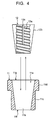
- the female screw thread part 12a which is an engaging section of the fitting member 12 (see Fig. 4 ) is screwed onto the male screw part 13a on the outer peripheral surface of the reinforcing bar 13.
- an upper end portion of the fitting member 12 in the reinforcing bar locking device 10 is rendered somewhat protruding from the larger opening 11g of the body member 11.
- the reinforcing bar 13 contracts in its longitudinal direction, the plurality of fitting members 12 are pulled in a direction toward the reduced diameter of the through hole 11a of the body member 11 as shown in Fig. 12 while the plurality of fitting members 12 are maintained to engage with the reinforcing bar 13, and the outer peripheral surface 12b (conical surface) of the fitting members 12 is brought into surface contact with the inner peripheral surface 11b of the through hole 11a of the body member 11 and locked thereon. Accordingly, since the reinforcing bar locking device 10 is fixed on the end face 14b of the block 14 while being locked with the reinforcing bar 13, the reinforcing bar 13 is fixed while the tensile force is being applied to the reinforcing bar 13.
- the body member 11 mounted from the end portion 13b of the reinforcing bar 13 can be moved up to the end face 14b of the block 14 without turning the body member 11 at all. Therefore, the body member 11 can be easily locked at a position relatively far from the end portion 13b of the reinforcing bar 13. Moreover, with the contracting force of the reinforcing bar 13 after releasing the tensile force T, the reinforcing bar 13, the fitting member 12, and the body member 11 are locked in an integrated manner, which exhibits a strong locking force applied to the reinforcing bar 13.
- the female screw thread part 12a which engages with the male screw part 13a formed on the outer peripheral surface of the reinforcing bar 13 is formed on the inner peripheral surface of the fitting member 12 as the engaging section. Therefore, the fitting member 12 and the reinforcing bar 13 can be firmly engaged with each other, applying a strong locking force to the reinforcing bar 13. Furthermore, as shown in Figs. 7 to 9 and other figures, the slit 12c is opened in each of the pair of fitting members 12.
- the fitting members 12 themselves are deformable so as to reduce their diameter due to a surface pressure applied by the inner peripheral surface 11b of the through hole 11a. Accordingly, a clamping action of the fitting members 12 exerted onto the reinforcing bar 13 is increased, thereby exhibiting an extremely strong locking force to the reinforcing bar 13.
- reinforcing bar locking devices 20 and 30 shown in Figs. 13 and 14 the members having the same functions and effects as those of the members of the above-described reinforcing bar locking device 10 bear the same reference numerals as in Figs. 1 to 12 , and the explanation thereof is omitted.
- the reinforcing bar locking device 20 shown in Fig. 13 has a pair of flat parts 21a formed on an outer periphery of a body member 21.
- the flat parts 21 a are arranged in parallel with each other on opposite sides of a center axis C of a through hole 11a.
- the reinforcing bar locking device 30 shown in Fig. 14 has three pairs of flat parts 31a formed on an outer periphery of a body member 31. Each pair of the flat parts 31a are arranged in parallel with each other on opposite sides of a center axis C of a through hole 11 a.
- the body members 21 and 31 can be turned by engaging a tool such as a wrench (not shown) with the flat parts 21a and 31a of the body members 21 and 31. Therefore, it is possible to tighten or loosen the reinforcing bar locking devices 20 and 30 locked with the reinforcing bar 13 as shown in Fig. 12 using a wrench or the like according to need.
- a tool such as a wrench (not shown)
- the advantages and effects of other members are the same as those of the reinforcing bar locking device 10 described above.
- the reinforcing bar locking device of the present invention is widely applicable in the construction industry or the like where various kinds of structures are constructed by fixing a reinforcing bar inserted into a plurality of arrayed blocks while applying a tensile force to the reinforcing bar.
Abstract
A reinforcing bar locking device that can be easily locked at a position relatively far from an end portion of a reinforcing bar and apply a strong locking force to the reinforcing bar. The reinforcing bar (10) has a body member (11) having a through hole (11a) in which the reinforcing bar is insertable and also has a pair of fitting members (12) fitted between the reinforcing bar inserted into the through hole (11a) and the inner peripheral surface of the through hole (11a). The inner peripheral surface (11b) of the through hole (11a) is of a funnel shape whose diameter is reduced in the direction of the center axis (C). A female screw thread part (12a) with which the reinforcing bar engages is formed on the inner peripheral surface of the fitting member (12). The outer peripheral surface (12b) of the fitting member (12) is a conical surface that has surface contact with the inner peripheral surface (11b) of the body member (11). On the outer periphery of the body member (11), a substantially cylindrical inserting section (11c) and a flange section (11d) having a larger diameter than the inserting section (11c) are provided. Each of the fitting members (12) has a slit (12c) opened in the direction of the center axis (C) of the through hole (11a).
Description
- The present invention relates to a reinforcing bar locking device for fixing a reinforcing bar inserted into a plurality of arrayed blocks while applying a tensile force to the reinforcing bar, which can be locked with the reinforcing bar exposed from an end face of the blocks.
- When a structure such as a block wall is built by stacking a plurality of concrete blocks, a reinforcing bar inserted into the blocks so as to run through hollow portions or the like in the blocks is often fixed while applying a tensile force to the reinforcing bar in order to increase the bonding force between the blocks. In this case, generally, the reinforcing bar is fixed by mounting a member having a function of a washer which is larger than the internal diameter of the hollow portions or the like and a nut on the end portion of the reinforcing bar exposed from the end face of the blocks and by tightening the nut (see
Patent Document 1, for example). - Patent Document 1: Japanese Patent Publication No.
S34-3622 - As shown in
Patent Document 1, by screwing and tightening a nut onto an end portion of a reinforcing bar protruding from an end face of a block which is positioned uppermost on a group of stacked blocks, the group of blocks can be fixed while applying a tensile force to the reinforcing bar. However, when the end portion of the reinforcing bar exposed from the end face of the block is long, the nut screwed onto the end portion of the reinforcing bar needs to be turned many times until the nut reaches the desired position on the end face of the block. Therefore, the operation of mounting the nut on the reinforcing bar is troublesome and takes a long time. - Accordingly, where a large number of reinforcing bars are used, for example, in building a large structure, a considerable amount of trouble and time is consumed in the operation of screwing and tightening the nuts onto the end portions of the reinforcing bars.
- An object of the present invention is to provide a reinforcing bar locking device which can be easily locked at a position relatively far from an end portion of a reinforcing bar and apply a relatively strong locking force to the reinforcing bar.
- A reinforcing bar locking device according to the present invention comprises a body member having a through hole in which a reinforcing bar is insertable; a plurality of fitting members which are fitted between the reinforcing bar inserted into the through hole and an inner peripheral surface of the through hole, the inner peripheral surface of the through hole having a funnel shape whose diameter is reduced in a direction of a center axis; an engaging section which engages with the reinforcing bar formed on an inner peripheral surface of the fitting members; and a conical surface which has surface contact with the inner peripheral surface of the body member formed on at least a part of an outer peripheral surface of the fitting members.
- By the above structure, the reinforcing bar locking device can be locked at a desired position on a reinforcing bar in the following process. First, a body member is mounted so that an end portion of a reinforcing bar protruding from an end face of a block penetrates from a smaller opening to a larger opening of a through hole of the body member. After the body member is moved along the reinforcing bar up to the end face of the block, a tensile force is applied to the reinforcing bar. Next, a plurality of fitting members are fitted between the reinforcing bar and an inner peripheral surface of the through hole while an engaging section of the fitting members is engaged with the reinforcing bar. Then, the tensile force applied to the reinforcing bar is released. In this way, the reinforcing bar contracts in a direction of a center axis so that the plurality of fitting members are pulled in a direction toward the reduced diameter of the through hole while engaging with the reinforcing bar, and a conical surface on an outer peripheral surface of the fitting members is brought into surface contact with the inner peripheral surface of the through hole of the body member and locked. Thus, the reinforcing bar locking device is locked at the desired position of the reinforcing bar (on the end face of the block, for example) so as not to move.
- In the above case, the body member mounted from the end portion of the reinforcing bar can be moved to the end face of the block without turning the body member. Therefore, the body member can be easily locked even at a position far from the end portion of the reinforcing bar. Furthermore, the reinforcing bar, the fitting members, and the body member can be locked in an integrated manner with the contracting force of the reinforcing bar after releasing the tensile force, which exhibits a relatively strong locking force applied to the reinforcing bar. It is also possible to interpose a washer member having a through hole for the reinforcing bar between the body member of the reinforcing bar locking device of the present invention and the end face of the block.
- As the engaging section, preferably, a female screw thread part which is screwed onto a male screw part formed on an outer peripheral surface of the reinforcing bar may be provided on the inner peripheral surface of the fitting member. By this structure, the fitting member can firmly engage with the reinforcing bar, which enhances the locking force with the reinforcing bar.
- Furthermore, the fitting member may be further provided with a slit which is opened in the direction of the center axis of the through hole. By this structure, after the tensile force is released, when the reinforcing bar and the fitting member move in the direction toward the reduced diameter of the through hole, the fitting member itself is deformable so as to reduce its diameter due to a surface pressure applied from the inner peripheral surface of the through hole. Therefore, a clamping force applied to the reinforcing bar by the fitting member is increased, resulting in further enhancement of the locking force to the reinforcing bar.
- In the meantime, the body member may be provided with, on an outer periphery thereof, at least a pair of flat parts arranged in parallel with each other on opposite sides of the center axis of the through hole. By this structure, a tool such as a wrench can engage with the flat parts of the body member to turn the body member. Thus, the reinforcing bar locking device locked on the reinforcing bar can be tightened or loosened using a wrench or the like.
- The present invention can provide a reinforcing bar locking device which can be easily locked at a position relatively far from an end portion of a reinforcing bar and apply a strong locking force to the reinforcing bar.
-
-
Fig. 1 is a plan view illustrating a reinforcing bar locking device of an embodiment of the present invention; -
Fig. 2 is a front view of the reinforcing bar locking device shown inFig. 1 ; -
Fig. 3 is a sectional view taken along the line A-A inFig. 1 ; -
Fig. 4 is an exploded view of the reinforcing bar locking device shown inFig. 3 ; -
Fig. 5 is a plan view of a body member which constitutes the reinforcing bar locking device shown inFig. 1 ; -
Fig. 6 is a front view of the body member shown inFig. 5 ; -
Fig. 7 is a plan view of a fitting member which constitutes the reinforcing bar locking device shown inFig. 1 ; -
Fig. 8 is a front view of the fitting member shown inFig. 7 ; -
Fig. 9 is a bottom view of the fitting member shown inFig. 7 ; -
Fig. 10 is a view illustrating the reinforcing bar locking device ofFig. 1 in use; -
Fig. 11 is a view illustrating the reinforcing bar locking device ofFig. 1 in use; -
Fig. 12 is a view illustrating the reinforcing bar locking device ofFig. 1 in use; -
Fig. 13 is a plan view illustrating a reinforcing bar locking device of another embodiment of the present invention; and -
Fig. 14 is a plan view illustrating a reinforcing bar locking device of yet another embodiment of the present invention. -
- 10, 20, 30: reinforcing bar locking device
- 11, 21, 31: body member
- 11 a: through hole
- 11b: inner peripheral surface
- 11c: inserting section
- 11d: flange section
- 11f: smaller opening
- 11g: larger opening
- 12: fitting member
- 12a: female screw thread part
- 12b: outer peripheral surface
- 12c: slit
- 13: reinforcing bar
- 13 a: male screw part
- 13b: end portion
- 14: block
- 14a: hollow part
- 14b: end face
- 15: plate member
- 15a: locking hole
- 21a, 31a: flat part
- C: center axis
- T: tensile force
- An embodiment of the present invention is explained below with reference to the drawings.
- As shown in
Figs. 1 to 10 , a reinforcingbar locking device 10 of the present embodiment includes abody member 11 having a throughhole 11 a in which a reinforcingbar 13 is inserted and a pair offitting members 12 which is fitted between the reinforcingbar 13 inserted into the throughhole 11 a and an inner peripheral surface of the throughhole 11a. An innerperipheral surface 11b of the throughhole 11a has a funnel shape whose diameter is reduced in a direction of a center axis. On an inner peripheral surface of thefitting member 12, a femalescrew thread part 12a is provided as an engaging section with the reinforcingbar 13. An outerperipheral surface 12b of thefitting member 12 is formed in a conical surface which has surface contact with the innerperipheral surface 11b of thebody member 11. On an outer periphery of thebody member 11, an insertingsection 11c which has a substantially cylindrical shape and aflange section 11d which has a larger external diameter than the insertingsection 11c are provided. - The two
fitting members 12 are positioned to oppose each other so that an outer appearance of thefitting members 12 forms an inverted, substantially truncated conical shape, and are inserted into the throughhole 11 a of thebody member 11. Inside the throughhole 11a, the femalescrew thread part 12a on the inner peripheral surface of thefitting members 12 is screwed onto amale screw part 13a formed on an outer peripheral surface of the reinforcingmember 13, thereby clamping the reinforcingbar 13. In each of thefitting members 12, aslit 12c is formed in the direction along the center axis C of the throughhole 11a. Theslit 12c is opened from an upper end toward a lower end of thefitting member 12. A length of theslit 12c is approximately 65 to 75% of a length of thefitting member 12 in the direction of the center axis C but is not limited to this length. - Next, referring to
Fig. 10 to 12 , a use of the reinforcingbar locking device 10 is explained below.Figs. 10 to 12 illustrate an example of construction where the reinforcingbar 13 is inserted into ahollow part 14a of stacked concrete blocks 14 and fixed while applying a tensile force to the reinforcingbar 13. - As shown in
Fig. 10 , on anend face 14b of theblock 14 positioned uppermost, aplate member 15 having a function of a washer is placed. Theplate member 15 has alocking hole 15a which has a smaller diameter than thehollow part 14a and allows the reinforcingbar 13 to pass therethrough. Anend portion 13b of the reinforcingbar 13 inserted into thehollow part 14a projects from the lockinghole 15a of theplate member 15. A lower end portion (not shown) of the reinforcingbar 13 is fixed to an end face of a block positioned lowermost (not shown). Thebody member 11 is mounted so that theend portion 13b of the reinforcingbar 13 passes through the throughhole 11a of thebody member 11 from asmaller opening 11f to alarger opening 11g. Then, thebody member 11 is moved along the reinforcingbar 13 up to theplate member 15 on theend face 14b of theblock 14, and the insertingsection 11c of thebody member 11 is inserted into thelocking hole 15a of theplate member 15, resulting in the state where theflange section 11d protrudes from an upper face of theplate member 15. - Next, a conventional hydraulic jack (not shown) is set on a side of the
end portion 13b of the reinforcingbar 13 to apply a tensile force T to the reinforcingbar 13. Then, as shown inFig. 11 , the twofitting members 12 are fit between the reinforcingbar 13 and the innerperipheral surface 11b of the throughhole 11a of thebody member 11, and clamp the reinforcingbar 13. In this case, the femalescrew thread part 12a which is an engaging section of the fitting member 12 (seeFig. 4 ) is screwed onto themale screw part 13a on the outer peripheral surface of the reinforcingbar 13. Thus, as shown inFig. 11 , an upper end portion of thefitting member 12 in the reinforcingbar locking device 10 is rendered somewhat protruding from thelarger opening 11g of thebody member 11. - After that, the tensile force T applied to the reinforcing
bar 13 is released. Then, as the reinforcingbar 13 contracts in its longitudinal direction, the plurality offitting members 12 are pulled in a direction toward the reduced diameter of the throughhole 11a of thebody member 11 as shown inFig. 12 while the plurality offitting members 12 are maintained to engage with the reinforcingbar 13, and the outerperipheral surface 12b (conical surface) of thefitting members 12 is brought into surface contact with the innerperipheral surface 11b of the throughhole 11a of thebody member 11 and locked thereon. Accordingly, since the reinforcingbar locking device 10 is fixed on theend face 14b of theblock 14 while being locked with the reinforcingbar 13, the reinforcingbar 13 is fixed while the tensile force is being applied to the reinforcingbar 13. - By using the reinforcing
bar locking device 10, thebody member 11 mounted from theend portion 13b of the reinforcingbar 13 can be moved up to theend face 14b of theblock 14 without turning thebody member 11 at all. Therefore, thebody member 11 can be easily locked at a position relatively far from theend portion 13b of the reinforcingbar 13. Moreover, with the contracting force of the reinforcingbar 13 after releasing the tensile force T, the reinforcingbar 13, thefitting member 12, and thebody member 11 are locked in an integrated manner, which exhibits a strong locking force applied to the reinforcingbar 13. - In addition, as shown in
Figs. 3 and4 , the femalescrew thread part 12a which engages with themale screw part 13a formed on the outer peripheral surface of the reinforcingbar 13 is formed on the inner peripheral surface of thefitting member 12 as the engaging section. Therefore, thefitting member 12 and the reinforcingbar 13 can be firmly engaged with each other, applying a strong locking force to the reinforcingbar 13. Furthermore, as shown inFigs. 7 to 9 and other figures, theslit 12c is opened in each of the pair offitting members 12. Thus, when the reinforcingbar 13 and thefitting members 12 move in the direction toward the reduced diameter of the throughhole 11a of thebody member 11 by the contracting force of the reinforcingbar 13 after the tensile force T is released, thefitting members 12 themselves are deformable so as to reduce their diameter due to a surface pressure applied by the innerperipheral surface 11b of the throughhole 11a. Accordingly, a clamping action of thefitting members 12 exerted onto the reinforcingbar 13 is increased, thereby exhibiting an extremely strong locking force to the reinforcingbar 13. - Next, with reference to
Figs. 13 and 14 , other embodiments of the present invention are explained below. In reinforcingbar locking devices Figs. 13 and 14 , the members having the same functions and effects as those of the members of the above-described reinforcingbar locking device 10 bear the same reference numerals as inFigs. 1 to 12 , and the explanation thereof is omitted. - The reinforcing
bar locking device 20 shown inFig. 13 has a pair offlat parts 21a formed on an outer periphery of abody member 21. Theflat parts 21 a are arranged in parallel with each other on opposite sides of a center axis C of a throughhole 11a. The reinforcingbar locking device 30 shown inFig. 14 has three pairs offlat parts 31a formed on an outer periphery of abody member 31. Each pair of theflat parts 31a are arranged in parallel with each other on opposite sides of a center axis C of a throughhole 11 a. - In the above structures, the
body members flat parts body members bar locking devices bar 13 as shown inFig. 12 using a wrench or the like according to need. The advantages and effects of other members are the same as those of the reinforcingbar locking device 10 described above. - The reinforcing bar locking device of the present invention is widely applicable in the construction industry or the like where various kinds of structures are constructed by fixing a reinforcing bar inserted into a plurality of arrayed blocks while applying a tensile force to the reinforcing bar.
Claims (4)
- A reinforcing bar locking device comprising:a body member having a through hole in which a reinforcing bar is insertable;a plurality of fitting members which are fitted between the reinforcing bar inserted into the through hole and an inner peripheral surface of the through hole, the inner peripheral surface of the through hole having a funnel shape whose diameter is reduced in a direction of a center axis;an engaging section which engages with the reinforcing bar formed on an inner peripheral surface of the fitting members; anda conical surface which has surface contact with the inner peripheral surface of the body member formed on at least a part of an outer peripheral surface of the fitting members.
- The reinforcing bar locking device according to claim 1, wherein the engaging section is a female screw thread part provided on the inner peripheral surface of the fitting members, the female screw thread part being screwed onto a male screw part formed on an outer peripheral surface of the reinforcing bar.
- The reinforcing bar locking device according to claim 1, wherein the fitting members have a slit opened in the direction of the center axis of the through hole.
- The reinforcing bar locking device according to claim 1, wherein the body member has at least a pair of flat parts arranged in parallel with each other on opposite sides of the center axis of the through hole on an outer periphery of the body member.
Applications Claiming Priority (2)
| Application Number | Priority Date | Filing Date | Title |
|---|---|---|---|
| JP2006009843A JP4822853B2 (en) | 2006-01-18 | 2006-01-18 | Rebar locker |
| PCT/JP2006/321651 WO2007083428A1 (en) | 2006-01-18 | 2006-10-30 | Reinforcing-bar engagement device |
Publications (1)
| Publication Number | Publication Date |
|---|---|
| EP1975422A1 true EP1975422A1 (en) | 2008-10-01 |
Family
ID=38287388
Family Applications (1)
| Application Number | Title | Priority Date | Filing Date |
|---|---|---|---|
| EP06812161A Withdrawn EP1975422A1 (en) | 2006-01-18 | 2006-10-30 | Reinforcing-bar engagement device |
Country Status (7)
| Country | Link |
|---|---|
| US (1) | US20100186340A1 (en) |
| EP (1) | EP1975422A1 (en) |
| JP (1) | JP4822853B2 (en) |
| CN (1) | CN101346550A (en) |
| CA (1) | CA2631508A1 (en) |
| RU (1) | RU2397377C2 (en) |
| WO (1) | WO2007083428A1 (en) |
Cited By (4)
| Publication number | Priority date | Publication date | Assignee | Title |
|---|---|---|---|---|
| CN103994139A (en) * | 2014-06-06 | 2014-08-20 | 国家电网公司 | Cushioned nut with torsion bulge |
| WO2015189225A1 (en) * | 2014-06-10 | 2015-12-17 | Firep Rebar Technology Gmbh | High-strength fastening device |
| EP3926112A1 (en) * | 2020-06-17 | 2021-12-22 | Alca plast, s.r.o. | Fixing support for anchoring supporting frames of sanitary facilities to masonry |
| EP4001527A1 (en) * | 2020-11-23 | 2022-05-25 | Nextrend GmbH | Wall holder, in particular for a sanitary object |
Families Citing this family (8)
| Publication number | Priority date | Publication date | Assignee | Title |
|---|---|---|---|---|
| CN103452306B (en) * | 2013-08-20 | 2016-07-06 | 广西建工集团第三建筑工程有限责任公司 | A kind of employing pre-buried wall tie bar tool-typed formwork of anchoring method |
| CA2946531C (en) * | 2014-05-19 | 2018-08-07 | Felix Sorkin | Modified permanent cap |
| CN104141363B (en) * | 2014-06-04 | 2016-08-24 | 兰州铁信土建新技术有限公司 | Combination grip formula prestressed anchor after one |
| WO2016207371A1 (en) * | 2015-06-26 | 2016-12-29 | Danmarks Tekniske Universitet | Anchorage device |
| CN106284849A (en) * | 2016-09-26 | 2017-01-04 | 昆山生态屋建筑技术有限公司 | A kind of splicing rack deformed bar anchorage |
| JP6960759B2 (en) * | 2017-04-21 | 2021-11-05 | 前田建設工業株式会社 | Structure using lightweight members |
| US10378257B2 (en) * | 2017-07-26 | 2019-08-13 | Fca Us Llc | Nut for threaded hinge pin |
| CN108799310A (en) * | 2018-08-27 | 2018-11-13 | 安徽西马新能源技术有限公司 | A kind of automobile installation fastening assembly |
Family Cites Families (20)
| Publication number | Priority date | Publication date | Assignee | Title |
|---|---|---|---|---|
| US570786A (en) * | 1896-11-03 | Expansion-bolt | ||
| US1120368A (en) * | 1911-11-27 | 1914-12-08 | Booraem & Rohmer Patent Company | Expansion-bolt. |
| US2180866A (en) * | 1938-07-20 | 1939-11-21 | John A Cryer | Connector |
| JPS531925A (en) * | 1976-06-25 | 1978-01-10 | Hasegawa Komuten Kk | Fixation fittings of reinforcement |
| DE3438355A1 (en) * | 1984-10-19 | 1986-04-24 | Philipp Holzmann Ag, 6000 Frankfurt | Wedge anchorage for tensioning wire strands |
| AT390100B (en) * | 1985-03-05 | 1990-03-12 | Vorspann Technik Gmbh | ANCHORAGE FOR TENSION LINKS |
| FR2602258B1 (en) * | 1986-07-31 | 1988-11-04 | Freyssinet Int Stup | IMPROVEMENTS ON ANCHORING DEVICES FOR TENSIONED STRUCTURES |
| US4773198A (en) * | 1986-09-05 | 1988-09-27 | Continental Concrete Structures, Inc. | Post-tensioning anchorages for aggressive environments |
| DE19818739A1 (en) * | 1998-04-27 | 1999-10-28 | Fischer Artur Werke Gmbh | Fastening element for subsequent reinforcement connection, especially for earthquake protection |
| JP2002180668A (en) * | 2000-12-13 | 2002-06-26 | Shinko Wire Co Ltd | Connection device for tendons for prestressed concrete and connection method for prestressed concrete block using the same |
| JP2002227343A (en) * | 2001-02-02 | 2002-08-14 | Ps Corp | Engaging device of prestressing bar, connecting device and anchoring deice therefor |
| US6560939B2 (en) * | 2001-03-19 | 2003-05-13 | Felix L. Sorkin | Intermediate anchor and intermediate anchorage system for a post-tension system |
| US6684585B2 (en) * | 2001-05-30 | 2004-02-03 | Robert Campbell | Method and apparatus for providing a visual indication of the tension applied to a tendon of a post-tension system |
| US6568757B2 (en) * | 2001-06-08 | 2003-05-27 | Ming Chuan Lin | Control device for seat post of office chairs |
| JP2004308203A (en) * | 2003-04-04 | 2004-11-04 | Nippon Steel Corp | Fixed holder structure of high strength wire rod |
| JP2004346575A (en) * | 2003-05-21 | 2004-12-09 | Nippon Electric Glass Co Ltd | Glass block and glass block structure using the same |
| US7726082B2 (en) * | 2004-12-04 | 2010-06-01 | Hayes Specialty Machining Ltd. | Anchor wedge configuration for tendon anchors |
| US20060179742A1 (en) * | 2005-02-14 | 2006-08-17 | Precision Surelock, Inc. | Anchor for concrete post-tension anchoring |
| KR100780088B1 (en) * | 2005-12-05 | 2007-11-29 | 신종덕 | Internal fixer for anchor having releasable tensioning steel wire |
| US7765752B2 (en) * | 2008-02-20 | 2010-08-03 | Hayes Specialty Machining, Ltd. | Anchor system with substantially longitudinally equal wedge compression |
-
2006
- 2006-01-18 JP JP2006009843A patent/JP4822853B2/en not_active Expired - Fee Related
- 2006-10-30 CA CA002631508A patent/CA2631508A1/en not_active Abandoned
- 2006-10-30 WO PCT/JP2006/321651 patent/WO2007083428A1/en active Application Filing
- 2006-10-30 EP EP06812161A patent/EP1975422A1/en not_active Withdrawn
- 2006-10-30 CN CNA2006800491223A patent/CN101346550A/en active Pending
- 2006-10-30 US US12/087,898 patent/US20100186340A1/en not_active Abandoned
- 2006-10-30 RU RU2008127226/11A patent/RU2397377C2/en not_active IP Right Cessation
Non-Patent Citations (1)
| Title |
|---|
| See references of WO2007083428A1 * |
Cited By (4)
| Publication number | Priority date | Publication date | Assignee | Title |
|---|---|---|---|---|
| CN103994139A (en) * | 2014-06-06 | 2014-08-20 | 国家电网公司 | Cushioned nut with torsion bulge |
| WO2015189225A1 (en) * | 2014-06-10 | 2015-12-17 | Firep Rebar Technology Gmbh | High-strength fastening device |
| EP3926112A1 (en) * | 2020-06-17 | 2021-12-22 | Alca plast, s.r.o. | Fixing support for anchoring supporting frames of sanitary facilities to masonry |
| EP4001527A1 (en) * | 2020-11-23 | 2022-05-25 | Nextrend GmbH | Wall holder, in particular for a sanitary object |
Also Published As
| Publication number | Publication date |
|---|---|
| CN101346550A (en) | 2009-01-14 |
| CA2631508A1 (en) | 2007-07-26 |
| JP2007192272A (en) | 2007-08-02 |
| US20100186340A1 (en) | 2010-07-29 |
| JP4822853B2 (en) | 2011-11-24 |
| RU2397377C2 (en) | 2010-08-20 |
| WO2007083428A1 (en) | 2007-07-26 |
| RU2008127226A (en) | 2010-02-27 |
Similar Documents
| Publication | Publication Date | Title |
|---|---|---|
| EP1975422A1 (en) | Reinforcing-bar engagement device | |
| JP2010043678A (en) | Locking bolt | |
| WO2006046660A1 (en) | Shape of screw and screw part having the same | |
| US20100003074A1 (en) | Connecting structure of steel bar | |
| JPH06159345A (en) | Loosening prevention screw | |
| EP3587842A1 (en) | Fastening structure | |
| JP2017025962A (en) | Fastener, fastening structure and fastening method | |
| JP2006336755A (en) | Locknut | |
| EP1964996A1 (en) | Reinforcing-bar connector | |
| JP6077168B1 (en) | Fastening member | |
| WO1992001165A1 (en) | Screw, nut, and thread rolling die | |
| KR20190119403A (en) | A bolt to be fastened bidirectionally for extension | |
| KR100988526B1 (en) | A combination means having a anti-looseness implement. | |
| JP2009185845A (en) | Fastening member | |
| JP4687040B2 (en) | Connection device for concrete components | |
| JP4657271B2 (en) | Tightening structure and building member connection structure | |
| KR200387963Y1 (en) | Anchor bolt | |
| KR200236761Y1 (en) | Contract tool to link plexible spiral pipe for distributing wires | |
| EP4180589A1 (en) | Rebar coupler with locking nut | |
| KR200415212Y1 (en) | A nut for preventing loose | |
| JP3205510U (en) | Fasteners used to install single pipes | |
| JP2008002161A (en) | Fastener for crossing of reinforcements for heavy load | |
| JP2001271820A (en) | Locking nut | |
| KR200339479Y1 (en) | The prevention nut which comes loose | |
| JP2006132686A (en) | Fastener |
Legal Events
| Date | Code | Title | Description |
|---|---|---|---|
| PUAI | Public reference made under article 153(3) epc to a published international application that has entered the european phase |
Free format text: ORIGINAL CODE: 0009012 |
|
| 17P | Request for examination filed |
Effective date: 20080606 |
|
| AK | Designated contracting states |
Kind code of ref document: A1 Designated state(s): AT BE BG CH CY CZ DE DK EE ES FI FR GB GR HU IE IS IT LI LT LU LV MC NL PL PT RO SE SI SK TR |
|
| RAP1 | Party data changed (applicant data changed or rights of an application transferred) |
Owner name: TAMA HOME CO., LTD. |
|
| STAA | Information on the status of an ep patent application or granted ep patent |
Free format text: STATUS: THE APPLICATION IS DEEMED TO BE WITHDRAWN |
|
| 18D | Application deemed to be withdrawn |
Effective date: 20110503 |