EP1975377A2 - Expansion turbine having a variable nozzle mechanism - Google Patents
Expansion turbine having a variable nozzle mechanism Download PDFInfo
- Publication number
- EP1975377A2 EP1975377A2 EP08251243A EP08251243A EP1975377A2 EP 1975377 A2 EP1975377 A2 EP 1975377A2 EP 08251243 A EP08251243 A EP 08251243A EP 08251243 A EP08251243 A EP 08251243A EP 1975377 A2 EP1975377 A2 EP 1975377A2
- Authority
- EP
- European Patent Office
- Prior art keywords
- nozzle
- turbine impeller
- turbine
- plate
- driving member
- Prior art date
- Legal status (The legal status is an assumption and is not a legal conclusion. Google has not performed a legal analysis and makes no representation as to the accuracy of the status listed.)
- Granted
Links
- 230000010355 oscillation Effects 0.000 claims description 6
- 239000007789 gas Substances 0.000 description 13
- 238000012423 maintenance Methods 0.000 description 11
- 238000007689 inspection Methods 0.000 description 4
- 230000015556 catabolic process Effects 0.000 description 2
- 238000010276 construction Methods 0.000 description 2
- 238000006731 degradation reaction Methods 0.000 description 2
- 238000010586 diagram Methods 0.000 description 2
- 239000011810 insulating material Substances 0.000 description 2
- 231100000989 no adverse effect Toxicity 0.000 description 2
- 230000001105 regulatory effect Effects 0.000 description 2
- 238000007792 addition Methods 0.000 description 1
- 239000000853 adhesive Substances 0.000 description 1
- 230000001070 adhesive effect Effects 0.000 description 1
- 230000002411 adverse Effects 0.000 description 1
- 239000011248 coating agent Substances 0.000 description 1
- 238000000576 coating method Methods 0.000 description 1
- 238000011161 development Methods 0.000 description 1
- 230000000694 effects Effects 0.000 description 1
- 239000011521 glass Substances 0.000 description 1
- 239000001307 helium Substances 0.000 description 1
- 229910052734 helium Inorganic materials 0.000 description 1
- SWQJXJOGLNCZEY-UHFFFAOYSA-N helium atom Chemical compound [He] SWQJXJOGLNCZEY-UHFFFAOYSA-N 0.000 description 1
- 239000007788 liquid Substances 0.000 description 1
- 238000000034 method Methods 0.000 description 1
- 238000012986 modification Methods 0.000 description 1
- 230000004048 modification Effects 0.000 description 1
- 229910001220 stainless steel Inorganic materials 0.000 description 1
- 239000010935 stainless steel Substances 0.000 description 1
- 238000006467 substitution reaction Methods 0.000 description 1
- 238000012546 transfer Methods 0.000 description 1
Images



Classifications
-
- F—MECHANICAL ENGINEERING; LIGHTING; HEATING; WEAPONS; BLASTING
- F02—COMBUSTION ENGINES; HOT-GAS OR COMBUSTION-PRODUCT ENGINE PLANTS
- F02C—GAS-TURBINE PLANTS; AIR INTAKES FOR JET-PROPULSION PLANTS; CONTROLLING FUEL SUPPLY IN AIR-BREATHING JET-PROPULSION PLANTS
- F02C1/00—Gas-turbine plants characterised by the use of hot gases or unheated pressurised gases, as the working fluid
- F02C1/02—Gas-turbine plants characterised by the use of hot gases or unheated pressurised gases, as the working fluid the working fluid being an unheated pressurised gas
-
- F—MECHANICAL ENGINEERING; LIGHTING; HEATING; WEAPONS; BLASTING
- F01—MACHINES OR ENGINES IN GENERAL; ENGINE PLANTS IN GENERAL; STEAM ENGINES
- F01D—NON-POSITIVE DISPLACEMENT MACHINES OR ENGINES, e.g. STEAM TURBINES
- F01D15/00—Adaptations of machines or engines for special use; Combinations of engines with devices driven thereby
- F01D15/005—Adaptations for refrigeration plants
-
- F—MECHANICAL ENGINEERING; LIGHTING; HEATING; WEAPONS; BLASTING
- F01—MACHINES OR ENGINES IN GENERAL; ENGINE PLANTS IN GENERAL; STEAM ENGINES
- F01D—NON-POSITIVE DISPLACEMENT MACHINES OR ENGINES, e.g. STEAM TURBINES
- F01D17/00—Regulating or controlling by varying flow
- F01D17/10—Final actuators
- F01D17/12—Final actuators arranged in stator parts
- F01D17/14—Final actuators arranged in stator parts varying effective cross-sectional area of nozzles or guide conduits
- F01D17/16—Final actuators arranged in stator parts varying effective cross-sectional area of nozzles or guide conduits by means of nozzle vanes
- F01D17/165—Final actuators arranged in stator parts varying effective cross-sectional area of nozzles or guide conduits by means of nozzle vanes for radial flow, i.e. the vanes turning around axes which are essentially parallel to the rotor centre line
-
- F—MECHANICAL ENGINEERING; LIGHTING; HEATING; WEAPONS; BLASTING
- F25—REFRIGERATION OR COOLING; COMBINED HEATING AND REFRIGERATION SYSTEMS; HEAT PUMP SYSTEMS; MANUFACTURE OR STORAGE OF ICE; LIQUEFACTION SOLIDIFICATION OF GASES
- F25B—REFRIGERATION MACHINES, PLANTS OR SYSTEMS; COMBINED HEATING AND REFRIGERATION SYSTEMS; HEAT PUMP SYSTEMS
- F25B9/00—Compression machines, plants or systems, in which the refrigerant is air or other gas of low boiling point
- F25B9/06—Compression machines, plants or systems, in which the refrigerant is air or other gas of low boiling point using expanders
-
- F—MECHANICAL ENGINEERING; LIGHTING; HEATING; WEAPONS; BLASTING
- F05—INDEXING SCHEMES RELATING TO ENGINES OR PUMPS IN VARIOUS SUBCLASSES OF CLASSES F01-F04
- F05D—INDEXING SCHEME FOR ASPECTS RELATING TO NON-POSITIVE-DISPLACEMENT MACHINES OR ENGINES, GAS-TURBINES OR JET-PROPULSION PLANTS
- F05D2220/00—Application
- F05D2220/70—Application in combination with
- F05D2220/76—Application in combination with an electrical generator
Definitions
- the present invention relates to expansion turbine having a variable nozzle mechanism used in large refrigerators such as helium refrigerator.
- Priority is claimed on Japanese Patent Application No. 2007-89478, filed March 29, 2007 , the content of which is incorporated herein by reference.
- variable nozzle mechanism 10 comprises a nozzle member 14 used to change the throat area of very low temperature gas introduced into a turbine impeller 12, and a driving member 16 used to drive the nozzle member 14.
- the nozzle member 14 is built into an adiabatic expansion device 20 located in a vacuum container 18.
- the driving member 16 is disposed outside the vacuum container 18 so as to not expose it to low temperatures and thereby ensure mechanical reliability.
- the nozzle member 14 and the driving member 16 are connected to each other by a thin cylindrical member 22 coaxial with a turbine impeller 12.
- the nozzle member 14 is driven by the oscillation of the cylindrical member 22 around the axial center C of the turbine impeller 12.
- the nozzle member 14 is disposed to surround the turbine impeller 12. It includes a plurality of movable nozzle plates 14a each oscillatably supported by a support pin 24, and a drive disc 28 connected to the inside end of a cylindrical member 22 and to each of the movable nozzle plate 14a by a drive pin 26. These are pressed against the adiabatic expansion device 20 after receiving a biasing force in the direction of the axial center C by a retaining -spring 30.
- the driving member 16 comprises a rotating drive device 36 such as a pulse motor for driving an oscillatable gear 32 through a gear 34 with the center as the axial center C of the turbine impeller 12 connected to the outside end of the cylindrical member 22.
- This variable nozzle mechanism 10 oscillates the cylindrical member 22 about the axial center C of the turbine impeller 12 by driving the rotating drive device 36, oscillates the drive disc 28, and oscillatably drives the movable nozzle plate 14a about the support pin 24 taken as the center, and changes the angle of the movable nozzle plate 14a. In this manner, by continuously changing the throat area of the variable nozzle, the flow rate of gas passing through is regulated.
- the driving member 16, the cylindrical member 22, the gear 32 and the drive unit 40 including the rotor shaft 38 are configured to be removed as an integral body from the adiabatic expansion device 20 in the vacuum container 18.
- variable nozzle mechanism 10 of the conventional expansion turbine mentioned above, when the drive unit 40 is removed from the adiabatic expansion device 20 in the vacuum container 18 during maintenance, the turbine impeller 12 and the nozzle member 14 tend to be left behind in the vacuum container 18 on the low temperature side. For this reason, when the nozzle member 14 is removed for inspection of coating condition of nozzle or replacement of parts, it becomes necessary to break the vacuum within the vacuum container 18 once, and then remove the nozzle member 14 from the low temperature piping, thus necessitating disassembly work on the low temperature piping side of the vacuum container 18.
- the present invention has the object of offering an expansion turbine having a variable nozzle mechanism that enables the nozzle member to be removed easily together with the drive unit, permits maintenance to be performed easily, and moreover has no adverse effect on the original performance of the expansion turbine.
- the present invention makes use of the structure below for resolving the aforementioned issues in the expansion turbine having a variable nozzle mechanism.
- the present invention is an expansion turbine with a variable nozzle mechanism comprising: an adiabatic expansion device located in a vacuum container having a turbine impeller threrein which rotates and drives the turbine impeller during adiabatic expansion of very low temperature gas, and varies the throat area of very low temperature gas introduced in the turbine impeller by driving a nozzle member disposed near the outside end of the adiabatic expansion device by a drive force from a driving member located outside the vacuum container; and a plate member provided detachably in contact with the outside end of the body of the adiabatic expansion device, wherein the support side of the nozzle member is connected to and supported by the plate member, and the drive side of the nozzle member is connected to and supported by the driving member.
- the support side of the nozzle member is connected to and supported by the plate member, and the drive side of the nozzle member is connected to and supported by the driving member.
- the plate member is provided detachably in contact with the outside end of the body of the adiabatic expansion device located inside the vacuum container.
- the plate member and the driving member may be disposed in the axial direction of the turbine impeller such that they are in close contact with the trailing faces of the nozzle member in the expansion turbine having a variable nozzle mechanism mentioned above.
- very low temperature gas is introduced into the turbine impeller without flowing through these clearances because plate member and the driving member are in close contact with the trailing faces of the nozzle member in the axial direction of the turbine impeller.
- the nozzle member may be disposed to surround the turbine impeller and may be composed of a plurality of movable nozzle plates each of which is oscillatably connected to and supported by the plate member through a support pin, and each movable nozzle plate may be connected to and supported by the driving member through a drive pin.
- a plurality of movable nozzle plates is each connected to and supported by a plate member through a support pin, and the driving member is connected to and supported by each movable nozzle plate through the drive pin.
- the driving member, a plurality of movable nozzle plates and the plate member are connected to each other in the axial direction.
- a first internally threaded hole may be provided on the support side of the movable nozzle plate looking toward a direction coaxial with the turbine impeller, an externally threaded part formed at one end of the support pin may be fitted into the first internally threaded hole, and the other end of the support pin may be connected to be circularly movable in the recess hole provided so as to face the first internally threaded hole in the plate member, a longitudinal hole may be provided looking toward a direction coaxial with the turbine impeller on the drive side of the movable nozzle plate, a second internally threaded hole may be provided facing the longitudinal hole in the driving member, the externally threaded part formed in one end of the drive pin may be fitted into the second internally threaded hole, and the other end of the drive pin may be guidably connected to the longitudinal hole.
- each movable nozzle plate is screwed and connected to the plate member and the drive side of each movable nozzle plate is screwed and connected to the driving member.
- the other end of each drive pin is guidably connected to the longitudinal hole of each movable nozzle plate.
- the outside end of the driving member may be connected to the inside end of the cylindrical member disposed coaxially with the turbine impeller, and the driving member may be driven by the oscillation of the cylindrical member about the axial center of the turbine impeller.
- the cylindrical member, the driving member, the movable nozzle plate, and the plate member are connected in the axial direction, and the transfer of heat from the thin cylindrical member to the adiabatic expansion device reduces.
- the nozzle member of the variable nozzle mechanism of the expansion turbine is integrated with the drive unit, and can therefore be removed easily. Moreover, disassembly of the vacuum container is not necessary when removing the nozzle member. As a result, the maintenance of the expansion turbine is simplified, and the efficiency of maintenance and inspection work can be enhanced.
- FIG. 1 is the overall configuration view showing an example of expansion turbine having a variable nozzle mechanism 42 related to the present embodiment.
- FIG. 2 is an expanded view of part A of FIG. 1 .
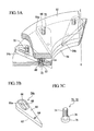
- FIG. 3A to FIG. 3B are perspective views showing an example of construction of variable nozzle unit.
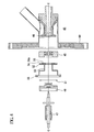
- FIG. 4 is a partial exploded view of the drive unit side.
- the expansion turbine 42 comprises an adiabatic expansion device 44, insulating material 45, a rotor shaft 47, a bearing 49, a retaining spring 51, a braking device 46, and a variable nozzle mechanism 100, and also a casing 90 to accommodate all these items.
- the adiabatic expansion device 44 is located in the low temperature side region within a vacuum container 48 and includes a built-in turbine impeller 50. It rotates and drives a turbine impeller 50 when it adiabatically expands very low temperature gas (such as gas with a temperature of 4 K to 64 K).
- This insulating material 45 is provided in the boundary portion on the low temperature side, suppresses the heat input from the room temperature side, and it may be made of glass FRP and the like.
- the rotor shaft 47 is rotatably supported by bearing 49, and transmits the rotation of the turbine impeller 50 to the braking device 46 on the room temperature side.
- the braking device 46 is located on the room temperature side region outside the vacuum container 48.
- a motor generator (not shown) connected coaxially with the center as the axial center C of the turbine impeller 50 may be used for example, as the braking device 46.
- gas leak from the clearance between the driving member 52, nozzle member 54 and the adiabatic expansion device 44 is prevented, and as a result, the degradation in efficiency of the expansion turbine is prevented.
- variable nozzle mechanism 100 comprises a driving member 52 located on the room temperature side region outside the vacuum container 48, a nozzle member 54 disposed near the outside end of the body of the adiabatic expansion device 44 disposed on the inside end side of the driving member 52, and a plate member 56 located coaxially with the center as the axial center C so as to touch the outside end of the body of the adiabatic expansion device 44.
- the plate member 56 and the driving member 52 are disposed to touch the trailing faces 60, 62 of the nozzle member 54, and separate in the direction of the axial center C facing each other.
- the support side of the nozzle member 54 is connected to and supported by the plate member 56, and the drive side of the nozzle member 54 is connected to and supported by the driving member 52.
- the outside end of the driving member 52 is connected to the inside end of the thin cylindrical member 58 coaxial to the axial center C, and the driving member 52 is rotated circularly and driven by the oscillation of the cylindrical member 58 with the center as the axial center C.
- a large gear 86 is also connected to the outside end of the cylindrical member 58.
- This large gear 86 rotates circularly receiving the drive force from the drive shaft of the rotating drive device 88, and oscillates the cylindrical member 58.
- the driving member 52 is driven by the oscillation of the cylindrical member 58
- the nozzle member 54 drives and changes the throat area of the very low temperature gas introduced in the turbine impeller 50.
- the thin cylindrical member 58 can be made as thin as required for the drive of the nozzle member 54 (for example, a thickness of about 0.5 mm). If made thin in this way, the amount of heat transferred to the low temperature side from the cylindrical member 58 disposed on the room temperature side can be suppressed to a minimal level.
- the nozzle member 54 comprises a plurality of movable nozzle plates 54a disposed at a distance from each other on the circumference with the axial center C as the center, surrounding the turbine impeller (not shown).
- each movable nozzle plate 54a is offered as a cross-section of substantial teardrop shape, with its inside end face 60 touching the outside end face of the plate member 56.
- the outside end face 62 of the movable nozzle plate 54a is disposed to touch the inside end face of the driving member 52, and moreover, disposed such that the top side of the substantial teardrop shape faces the inward radial direction of circle about the axial center C, and the circular arc side faces the outward radial direction.
- a first internal threaded hole 64 is formed facing the axial center C in the topside part of the support side face 60 of the movable nozzle plate 54a, and a longitudinal hole 66 is formed in the longitudinal direction of the substantial teardrop shape in the circular arc side part. This longitudinal hole 66 is formed so as to penetrate the inside end face 60 and the outside end face 62 in the direction of the axial center C.
- the two ends in the longitudinal direction are semi-circles with substantially rectangular shape; however by forming a step 68 inside the movable nozzle plate 54a, the cross section cut along the axial center C becomes a protruded shape as shown in FIG. 2 , and the area of the longitudinal hole 66a of the outside end face 62 is formed to be smaller than the area of the longitudinal hole 66 of the inside end face 60.
- an externally threaded part 74 is formed in the front ends of the support pin 70 and the drive pin 72; at other ends, a large diameter head 76 larger than the diameter at the front end is formed. Furthermore, a externally threaded part 74 and a sliding part 78 of substantially the same diameter are formed between the head 76 and the externally threaded part 74.
- the externally threaded part 74 of the front end of the support pin 70 is screwed together with each first internal threaded hole 64 of the movable nozzle plate 54a.
- the head 76 of the support pin 70 and the sliding part 78 are provided such that the first internal threaded hole 64 is opposite to the plate member 56, and the side closer to the movable nozzle plate 54a is fitted into the recess hole 82 with narrowly formed step 80, so that the movable nozzle plate 54a and the plate member 56 are connected to be circularly movable, and these are supported in the direction of the axial center C.
- the externally threaded part 74 of the front end of the drive pin 72 is designed to fit into a second internally threaded hole 84 provided at a position facing the longitudinal hole 66a in the driving member 52.
- the head 76 and the sliding part 78 of the drive pin 72 are fitted loosely in longitudinal holes such that the head 76 can smoothly slide within the longitudinal hole 66 on the support side of the movable nozzle plate 54a and the sliding part 78 can smoothly slide within the longitudinal hole 66a on the drive side.
- the drive pin 72 is slidably connected to the movable nozzle plate 54a along the longitudinal hole 66, and at the same time, the driving member 52 and the movable nozzle plate 54a are supported in the direction of the axial center C.
- each movable nozzle plate 54a swings each of its support pins 70 connected to the plate member 56 to the center, and at the same time, the drive pin 72 and the head 76 and the sliding part 78 are guidably slid into the longitudinal hole 66 of the movable nozzle plate 54a so that the angle of disposition of the movable nozzle plate 54a is changed, and the throat area of the very low temperature gas introduced in the turbine impeller 50 is continuously varied.
- the externally threaded part 74 of the support pin 70 is screwed and connected to the first internal threaded hole 64 of the movable nozzle plate 54a.
- the head 76 gets caught in the direction of the axial center C by the step 80 in the recess hole 82; as a result, the support pin 70 is connected in the direction of the axial center C to the plate member 56 and the movable nozzle plate 54a.
- the externally threaded part 74 of the drive pin 72 is screwed and connected to the second internally threaded hole 84 of the driving member 52.
- the head 76 gets caught in the direction of the axial center C by the step 68 in the longitudinal hole 66; as a result, the drive pin 72 is connected in the direction of the axial center C to the driving member 52 and the movable nozzle plate 54a, and thus can slide in the longitudinal direction within the longitudinal hole 66.
- the driving member 52, the plurality of movable nozzle plates 54a, and the plate member 56 are connected firmly in the axial direction, and each movable nozzle plate 54a can vary the angle of disposition by driving the driving member 52.
- the driving member 52, the movable nozzle plate 54a, and the plate member 56 are integrated as a single unit in the axial direction, so for the maintenance of the movable nozzle plate 54a, as shown in FIG. 4 , the driving member 52, the movable nozzle plate 54a, and the plate member 56 can be removed as a single unit by pulling out the driving member 52 from the vacuum container 48 as was done conventionally.
- the plate member 56 can be removed from the movable nozzle plate 54a. Furthermore, by rotating the head 76 of the drive pin 72 and pulling it out, the movable nozzle plate 54a can be removed from the driving member 52. As a result, maintenance and replacement of the movable nozzle plate 54a can be performed.
- the nozzle member 54 which was often left behind in the adiabatic expansion device 44, when the driving member 52 was pulled out during maintenance of the variable nozzle mechanism 100 related to the present embodiment, can be easily removed together with the driving member 52; thus, maintenance such as inspection and replacement of nozzle parts can be performed more easily than before.
- stainless steel M1 screws formed with a cross hole in the head 76 may be used for the support pin 70 and the drive pin 72.
- the dimensions of various parts of the screw may be for example, as follows: diameter of sliding part 78 may be 1.2 mm; diameter of the head 76 may be 1.8 mm, and thickness of the head 76 may be 0.5 mm.
- liquid adhesive may be filled in the very small clearance at the interface of the internally threaded holes 64, 84 and the externally threaded part 74.
Landscapes
- Engineering & Computer Science (AREA)
- Mechanical Engineering (AREA)
- General Engineering & Computer Science (AREA)
- Physics & Mathematics (AREA)
- Thermal Sciences (AREA)
- Chemical & Material Sciences (AREA)
- Combustion & Propulsion (AREA)
- Control Of Turbines (AREA)
- Supercharger (AREA)
Abstract
Description
- The present invention relates to expansion turbine having a variable nozzle mechanism used in large refrigerators such as helium refrigerator. Priority is claimed on Japanese Patent Application No.
2007-89478, filed March 29, 2007 - Expansion turbines have been used conventionally to enhance the efficiency of refrigerators. To regulate the flow rate of gas introduced into such an expansion turbine, as shown in
FIG. 5 , expansion turbines usingvariable nozzle mechanism 10 are popularly used (for example, refer to the Japanese Unexamined Patent Application, First Publication No.2001-132410
Thisvariable nozzle mechanism 10 comprises a nozzle member 14 used to change the throat area of very low temperature gas introduced into aturbine impeller 12, and adriving member 16 used to drive the nozzle member 14. The nozzle member 14 is built into anadiabatic expansion device 20 located in avacuum container 18. The drivingmember 16 is disposed outside thevacuum container 18 so as to not expose it to low temperatures and thereby ensure mechanical reliability. - As shown in
FIG. 5 , the nozzle member 14 and thedriving member 16 are connected to each other by a thincylindrical member 22 coaxial with aturbine impeller 12.
The nozzle member 14 is driven by the oscillation of thecylindrical member 22 around the axial center C of theturbine impeller 12. The nozzle member 14 is disposed to surround theturbine impeller 12. It includes a plurality of movable nozzle plates 14a each oscillatably supported by asupport pin 24, and adrive disc 28 connected to the inside end of acylindrical member 22 and to each of the movable nozzle plate 14a by adrive pin 26. These are pressed against theadiabatic expansion device 20 after receiving a biasing force in the direction of the axial center C by a retaining -spring 30.
Moreover, the drivingmember 16 comprises a rotatingdrive device 36 such as a pulse motor for driving anoscillatable gear 32 through agear 34 with the center as the axial center C of theturbine impeller 12 connected to the outside end of thecylindrical member 22. - This
variable nozzle mechanism 10 oscillates thecylindrical member 22 about the axial center C of theturbine impeller 12 by driving the rotatingdrive device 36, oscillates thedrive disc 28, and oscillatably drives the movable nozzle plate 14a about thesupport pin 24 taken as the center, and changes the angle of the movable nozzle plate 14a. In this manner, by continuously changing the throat area of the variable nozzle, the flow rate of gas passing through is regulated. - In expansion turbines using such a conventional
variable nozzle mechanism 10, thedriving member 16, thecylindrical member 22, thegear 32 and thedrive unit 40 including therotor shaft 38 are configured to be removed as an integral body from theadiabatic expansion device 20 in thevacuum container 18. - However, in the
variable nozzle mechanism 10 of the conventional expansion turbine mentioned above, when thedrive unit 40 is removed from theadiabatic expansion device 20 in thevacuum container 18 during maintenance, theturbine impeller 12 and the nozzle member 14 tend to be left behind in thevacuum container 18 on the low temperature side. For this reason, when the nozzle member 14 is removed for inspection of coating condition of nozzle or replacement of parts, it becomes necessary to break the vacuum within thevacuum container 18 once, and then remove the nozzle member 14 from the low temperature piping, thus necessitating disassembly work on the low temperature piping side of thevacuum container 18.
In this way, it was very troublesome and required much efforts to remove the nozzle member 14 from thevariable nozzle mechanism 10 of the conventional expansion turbine; thus, maintenance work such as replacement and inspect ion of the nozzle member 14 was not easy. Particularly, when degradation or wear exists in the nozzle member 14, for instance, when the flow passage surface of the nozzle peels out or wears out, leak of gas passing through the throat is induced, which has an adverse effect on the performance of the expansion turbine.
For this reason, the development of a variable nozzle mechanism for which maintenance can be carried out easily and which has no adverse effect on the original performance of the expansion turbine, was demanded. - After considering the circumstances mentioned above, the present invention has the object of offering an expansion turbine having a variable nozzle mechanism that enables the nozzle member to be removed easily together with the drive unit, permits maintenance to be performed easily, and moreover has no adverse effect on the original performance of the expansion turbine.
- The present invention makes use of the structure below for resolving the aforementioned issues in the expansion turbine having a variable nozzle mechanism.
The present invention is an expansion turbine with a variable nozzle mechanism comprising: an adiabatic expansion device located in a vacuum container having a turbine impeller threrein which rotates and drives the turbine impeller during adiabatic expansion of very low temperature gas, and varies the throat area of very low temperature gas introduced in the turbine impeller by driving a nozzle member disposed near the outside end of the adiabatic expansion device by a drive force from a driving member located outside the vacuum container; and a plate member provided detachably in contact with the outside end of the body of the adiabatic expansion device, wherein the support side of the nozzle member is connected to and supported by the plate member, and the drive side of the nozzle member is connected to and supported by the driving member. - According to the present invention, the support side of the nozzle member is connected to and supported by the plate member, and the drive side of the nozzle member is connected to and supported by the driving member. The plate member is provided detachably in contact with the outside end of the body of the adiabatic expansion device located inside the vacuum container. As a result, the driving member, the nozzle member and the plate member are connected to each other in the axial direction.
- The plate member and the driving member may be disposed in the axial direction of the turbine impeller such that they are in close contact with the trailing faces of the nozzle member in the expansion turbine having a variable nozzle mechanism mentioned above.
- According to the present invention, very low temperature gas is introduced into the turbine impeller without flowing through these clearances because plate member and the driving member are in close contact with the trailing faces of the nozzle member in the axial direction of the turbine impeller.
- In the expansion turbine having a variable nozzle mechanism, the nozzle member may be disposed to surround the turbine impeller and may be composed of a plurality of movable nozzle plates each of which is oscillatably connected to and supported by the plate member through a support pin, and each movable nozzle plate may be connected to and supported by the driving member through a drive pin.
- According to the present invention, a plurality of movable nozzle plates is each connected to and supported by a plate member through a support pin, and the driving member is connected to and supported by each movable nozzle plate through the drive pin. As a result, the driving member, a plurality of movable nozzle plates and the plate member are connected to each other in the axial direction.
- In the expansion turbine having a variable nozzle mechanism mentioned above, a first internally threaded hole may be provided on the support side of the movable nozzle plate looking toward a direction coaxial with the turbine impeller, an externally threaded part formed at one end of the support pin may be fitted into the first internally threaded hole, and the other end of the support pin may be connected to be circularly movable in the recess hole provided so as to face the first internally threaded hole in the plate member, a longitudinal hole may be provided looking toward a direction coaxial with the turbine impeller on the drive side of the movable nozzle plate, a second internally threaded hole may be provided facing the longitudinal hole in the driving member, the externally threaded part formed in one end of the drive pin may be fitted into the second internally threaded hole, and the other end of the drive pin may be guidably connected to the longitudinal hole.
- According to the present invention, the support side of each movable nozzle plate is screwed and connected to the plate member and the drive side of each movable nozzle plate is screwed and connected to the driving member. Moreover, the other end of each drive pin is guidably connected to the longitudinal hole of each movable nozzle plate. As a result, the driving member, a plurality of movable nozzle plates, and the plate member is firmly connected in the axial direction, and each movable nozzle plate can vary the angle of disposition by driving the driving member.
- In the expansion turbine having a variable nozzle mechanism mentioned above, the outside end of the driving member may be connected to the inside end of the cylindrical member disposed coaxially with the turbine impeller, and the driving member may be driven by the oscillation of the cylindrical member about the axial center of the turbine impeller.
- According to the present invention, the cylindrical member, the driving member, the movable nozzle plate, and the plate member are connected in the axial direction, and the transfer of heat from the thin cylindrical member to the adiabatic expansion device reduces.
- Also, according to the present invention, the nozzle member of the variable nozzle mechanism of the expansion turbine is integrated with the drive unit, and can therefore be removed easily. Moreover, disassembly of the vacuum container is not necessary when removing the nozzle member.
As a result, the maintenance of the expansion turbine is simplified, and the efficiency of maintenance and inspection work can be enhanced. -
-
FIG. 1 is the overall configuration diagram showing an example of an expansion turbine having a variable nozzle mechanism related to the present invention. -
FIG. 2 is an expanded view of part A ofFIG. 1 . -
FIG. 3A to FIG. 3C are perspective views showing an example of construction of the variable nozzle unit of the variable nozzle mechanism of the expansion turbine related to the present invention. -
FIG. 4 is a partial exploded view of the drive unit side. -
FIG. 5 is an overall configuration diagram showing an example of a variable nozzle mechanism of a conventional expansion turbine. - The embodiments of the expansion turbine having a variable nozzle mechanism related to the present invention are described here referring to the drawings.
FIG. 1 is the overall configuration view showing an example of expansion turbine having avariable nozzle mechanism 42 related to the present embodiment.FIG. 2 is an expanded view of part A ofFIG. 1 .FIG. 3A to FIG. 3B are perspective views showing an example of construction of variable nozzle unit.FIG. 4 is a partial exploded view of the drive unit side. - As shown in
FIG. 1 , theexpansion turbine 42 comprises anadiabatic expansion device 44,insulating material 45, arotor shaft 47, abearing 49, aretaining spring 51, abraking device 46, and avariable nozzle mechanism 100, and also acasing 90 to accommodate all these items.
Theadiabatic expansion device 44 is located in the low temperature side region within avacuum container 48 and includes a built-inturbine impeller 50. It rotates and drives aturbine impeller 50 when it adiabatically expands very low temperature gas (such as gas with a temperature of 4 K to 64 K).
This insulatingmaterial 45 is provided in the boundary portion on the low temperature side, suppresses the heat input from the room temperature side, and it may be made of glass FRP and the like.
Therotor shaft 47 is rotatably supported by bearing 49, and transmits the rotation of theturbine impeller 50 to thebraking device 46 on the room temperature side.
Thebraking device 46 is located on the room temperature side region outside thevacuum container 48. A motor generator (not shown) connected coaxially with the center as the axial center C of theturbine impeller 50 may be used for example, as thebraking device 46.
Also, by energizing the retainingspring 51 so that it presses the drivingmember 52 and thenozzle member 54 mentioned later, toward theadiabatic expansion device 44, gas leak from the clearance between the drivingmember 52,nozzle member 54 and theadiabatic expansion device 44 is prevented, and as a result, the degradation in efficiency of the expansion turbine is prevented. - As shown in
FIG. 1 andFIG. 2 , thevariable nozzle mechanism 100 comprises a drivingmember 52 located on the room temperature side region outside thevacuum container 48, anozzle member 54 disposed near the outside end of the body of theadiabatic expansion device 44 disposed on the inside end side of the drivingmember 52, and aplate member 56 located coaxially with the center as the axial center C so as to touch the outside end of the body of theadiabatic expansion device 44.
Theplate member 56 and the drivingmember 52 are disposed to touch the trailing faces 60, 62 of thenozzle member 54, and separate in the direction of the axial center C facing each other. The support side of thenozzle member 54 is connected to and supported by theplate member 56, and the drive side of thenozzle member 54 is connected to and supported by the drivingmember 52.
The outside end of the drivingmember 52 is connected to the inside end of the thincylindrical member 58 coaxial to the axial center C, and the drivingmember 52 is rotated circularly and driven by the oscillation of thecylindrical member 58 with the center as the axial center C. - A
large gear 86 is also connected to the outside end of thecylindrical member 58. Thislarge gear 86 rotates circularly receiving the drive force from the drive shaft of therotating drive device 88, and oscillates thecylindrical member 58.
When the drivingmember 52 is driven by the oscillation of thecylindrical member 58, thenozzle member 54 drives and changes the throat area of the very low temperature gas introduced in theturbine impeller 50. As a result, the flow rate of gas passing through theturbine impeller 50 can be regulated. The thincylindrical member 58 can be made as thin as required for the drive of the nozzle member 54 (for example, a thickness of about 0.5 mm).
If made thin in this way, the amount of heat transferred to the low temperature side from thecylindrical member 58 disposed on the room temperature side can be suppressed to a minimal level. - As shown in
FIG. 2 andFIG. 3A , thenozzle member 54 comprises a plurality ofmovable nozzle plates 54a disposed at a distance from each other on the circumference with the axial center C as the center, surrounding the turbine impeller (not shown).
As shown inFIG. 3B , eachmovable nozzle plate 54a is offered as a cross-section of substantial teardrop shape, with its inside end face 60 touching the outside end face of theplate member 56. The outside end face 62 of themovable nozzle plate 54a is disposed to touch the inside end face of the drivingmember 52, and moreover, disposed such that the top side of the substantial teardrop shape faces the inward radial direction of circle about the axial center C, and the circular arc side faces the outward radial direction.
A first internal threadedhole 64 is formed facing the axial center C in the topside part of the support side face 60 of themovable nozzle plate 54a, and alongitudinal hole 66 is formed in the longitudinal direction of the substantial teardrop shape in the circular arc side part. Thislongitudinal hole 66 is formed so as to penetrate theinside end face 60 and the outside end face 62 in the direction of the axial center C. The two ends in the longitudinal direction are semi-circles with substantially rectangular shape; however by forming astep 68 inside themovable nozzle plate 54a, the cross section cut along the axial center C becomes a protruded shape as shown inFIG. 2 , and the area of thelongitudinal hole 66a of theoutside end face 62 is formed to be smaller than the area of thelongitudinal hole 66 of theinside end face 60. - As shown in
FIG. 3C , an externally threadedpart 74 is formed in the front ends of thesupport pin 70 and thedrive pin 72; at other ends, alarge diameter head 76 larger than the diameter at the front end is formed. Furthermore, a externally threadedpart 74 and a slidingpart 78 of substantially the same diameter are formed between thehead 76 and the externally threadedpart 74.
The externally threadedpart 74 of the front end of thesupport pin 70 is screwed together with each first internal threadedhole 64 of themovable nozzle plate 54a.
Thehead 76 of thesupport pin 70 and the slidingpart 78 are provided such that the first internal threadedhole 64 is opposite to theplate member 56, and the side closer to themovable nozzle plate 54a is fitted into therecess hole 82 with narrowly formedstep 80, so that themovable nozzle plate 54a and theplate member 56 are connected to be circularly movable, and these are supported in the direction of the axial center C. - The externally threaded
part 74 of the front end of thedrive pin 72 is designed to fit into a second internally threadedhole 84 provided at a position facing thelongitudinal hole 66a in the drivingmember 52. Thehead 76 and the slidingpart 78 of thedrive pin 72 are fitted loosely in longitudinal holes such that thehead 76 can smoothly slide within thelongitudinal hole 66 on the support side of themovable nozzle plate 54a and the slidingpart 78 can smoothly slide within thelongitudinal hole 66a on the drive side. As a result, thedrive pin 72 is slidably connected to themovable nozzle plate 54a along thelongitudinal hole 66, and at the same time, the drivingmember 52 and themovable nozzle plate 54a are supported in the direction of the axial center C. - When the driving
member 52 is driven in circular motion by the oscillation of thecylindrical member 58, eachmovable nozzle plate 54a swings each of its support pins 70 connected to theplate member 56 to the center, and at the same time, thedrive pin 72 and thehead 76 and the slidingpart 78 are guidably slid into thelongitudinal hole 66 of themovable nozzle plate 54a so that the angle of disposition of themovable nozzle plate 54a is changed, and the throat area of the very low temperature gas introduced in theturbine impeller 50 is continuously varied. - Next, the method of maintenance of the
expansion turbine 42 withvariable nozzle mechanism 100 mentioned above is described here.
The externally threadedpart 74 of thesupport pin 70 is screwed and connected to the first internal threadedhole 64 of themovable nozzle plate 54a. Thehead 76 gets caught in the direction of the axial center C by thestep 80 in therecess hole 82; as a result, thesupport pin 70 is connected in the direction of the axial center C to theplate member 56 and themovable nozzle plate 54a. On the other hand, the externally threadedpart 74 of thedrive pin 72 is screwed and connected to the second internally threadedhole 84 of the drivingmember 52. Thehead 76 gets caught in the direction of the axial center C by thestep 68 in thelongitudinal hole 66; as a result, thedrive pin 72 is connected in the direction of the axial center C to the drivingmember 52 and themovable nozzle plate 54a, and thus can slide in the longitudinal direction within thelongitudinal hole 66.
For this reason, the drivingmember 52, the plurality ofmovable nozzle plates 54a, and theplate member 56 are connected firmly in the axial direction, and eachmovable nozzle plate 54a can vary the angle of disposition by driving the drivingmember 52.
In thevariable nozzle mechanism 100 related to the present embodiment, the drivingmember 52, themovable nozzle plate 54a, and theplate member 56 are integrated as a single unit in the axial direction, so for the maintenance of themovable nozzle plate 54a, as shown inFIG. 4 , the drivingmember 52, themovable nozzle plate 54a, and theplate member 56 can be removed as a single unit by pulling out the drivingmember 52 from thevacuum container 48 as was done conventionally. - Moreover, after removal as a single unit, if the
head 76 of thesupport pin 70 is rotated and pulled out from theplate member 56, theplate member 56 can be removed from themovable nozzle plate 54a. Furthermore, by rotating thehead 76 of thedrive pin 72 and pulling it out, themovable nozzle plate 54a can be removed from the drivingmember 52. As a result, maintenance and replacement of themovable nozzle plate 54a can be performed. - Accordingly, the
nozzle member 54, which was often left behind in theadiabatic expansion device 44, when the drivingmember 52 was pulled out during maintenance of thevariable nozzle mechanism 100 related to the present embodiment, can be easily removed together with the drivingmember 52; thus, maintenance such as inspection and replacement of nozzle parts can be performed more easily than before. - In the embodiment mentioned above, stainless steel M1 screws formed with a cross hole in the
head 76 may be used for thesupport pin 70 and thedrive pin 72. In this case, the dimensions of various parts of the screw may be for example, as follows: diameter of slidingpart 78 may be 1.2 mm; diameter of thehead 76 may be 1.8 mm, and thickness of thehead 76 may be 0.5 mm.
Also, liquid adhesive may be filled in the very small clearance at the interface of the internally threadedholes part 74. - While preferred embodiments of the invention have been described and illustrated above, it should be understood that these are exemplary of the invention and are not to be considered as limiting. Additions, omissions, substitutions, and other modifications can be made without departing from the spirit or scope of the present invention. Accordingly, the invention is not to be considered as being limited by the foregoing description, and is only limited by the scope of the appended claims.
Claims (5)
- An expansion turbine with a variable nozzle mechanism comprising:an adiabatic expansion device located in a vacuum container having a turbine impeller threrein which rotates and drives the turbine impeller during adiabatic expansion of very low temperature gas, and varies the throat area of very low temperature gas introduced in the turbine impeller by driving a nozzle member disposed near the outside end of the adiabatic expansion device by a drive force from a driving member located outside the vacuum container; anda plate member provided detachably in contact with the outside end of the body of the adiabatic expansion device,wherein the support side of the nozzle member is connected to and supported by the plate member, andthe drive side of the nozzle member is connected to and supported by the driving member.
- The expansion turbine having a variable nozzle mechanism according to claim 1,
wherein the plate member and the driving member are each disposed in close contact with the trailing faces of the nozzle member in the axial direction of the turbine impeller. - The expansion turbine having a variable nozzle mechanism according to claim 1,
wherein the nozzle member is disposed to surround the turbine impeller and is composed of a plurality of movable nozzle plates each of which is oscillatably connected to and supported by the plate member through a support pin,
wherein each movable nozzle plate is connected to and supported by the driving member through a drive pin. - The expansion turbine having a variable nozzle mechanism according to claim 3,
wherein a first internally threaded hole is provided on the support side of the movable nozzle plate looking toward the direction coaxial with the turbine impeller, an externally threaded part formed at one end of the support pin is fitted into the first internally threaded hole, and the other end of the support pin is connected to be circularly movable in the recess hole provided so as face the first internally threaded hole in the plate member,
a longitudinal hole is provided looking toward the direction coaxial with the turbine impeller on the drive side of the movable nozzle plate, and
a second internally threaded hole is provided facing the longitudinal hole in the driving member, and
the externally threaded part formed in one end of the drive pin is fitted into the second internally threaded hole, and the other end of the drive pin is guidably connected to the longitudinal hole. - The expansion turbine having a variable nozzle mechanism according to claim 1,
wherein the outside end of the driving member is connected to the inside end of a cylindrical member disposed coaxially with the turbine impeller, and
the driving member is driven by oscillation of the cylindrical member about the axial center of the turbine impeller.
Applications Claiming Priority (1)
| Application Number | Priority Date | Filing Date | Title |
|---|---|---|---|
| JP2007089478A JP4930151B2 (en) | 2007-03-29 | 2007-03-29 | Expansion turbine with variable nozzle mechanism |
Publications (3)
| Publication Number | Publication Date |
|---|---|
| EP1975377A2 true EP1975377A2 (en) | 2008-10-01 |
| EP1975377A3 EP1975377A3 (en) | 2010-10-20 |
| EP1975377B1 EP1975377B1 (en) | 2014-09-24 |
Family
ID=39590449
Family Applications (1)
| Application Number | Title | Priority Date | Filing Date |
|---|---|---|---|
| EP08251243.5A Expired - Fee Related EP1975377B1 (en) | 2007-03-29 | 2008-03-31 | Expansion turbine having a variable nozzle mechanism |
Country Status (3)
| Country | Link |
|---|---|
| US (1) | US8113769B2 (en) |
| EP (1) | EP1975377B1 (en) |
| JP (1) | JP4930151B2 (en) |
Cited By (3)
| Publication number | Priority date | Publication date | Assignee | Title |
|---|---|---|---|---|
| CN102606229A (en) * | 2012-04-09 | 2012-07-25 | 三一能源重工有限公司 | Variable nozzle component of turbocharger |
| CN103206266A (en) * | 2013-04-15 | 2013-07-17 | 无锡科博增压器有限公司 | Efficient guide ring for turbocharger |
| CN104895623A (en) * | 2015-04-16 | 2015-09-09 | 西安交通大学 | Low temperature liquid expander nozzle |
Families Citing this family (3)
| Publication number | Priority date | Publication date | Assignee | Title |
|---|---|---|---|---|
| US10316696B2 (en) | 2015-05-08 | 2019-06-11 | General Electric Company | System and method for improving exhaust energy recovery |
| US9957900B2 (en) | 2015-05-11 | 2018-05-01 | General Electric Company | System and method for flow control in turbine |
| US20180023472A1 (en) * | 2016-07-22 | 2018-01-25 | Brent Wei-Teh LEE | Engine, rotary device, power generator, power generation system, and methods of making and using the same |
Citations (2)
| Publication number | Priority date | Publication date | Assignee | Title |
|---|---|---|---|---|
| JP2001132410A (en) | 1999-11-05 | 2001-05-15 | Japan Atom Energy Res Inst | Turbine expander with variable nozzle mechanism |
| JP2007089478A (en) | 2005-09-29 | 2007-04-12 | Daiwa Seiko Inc | Tubular body |
Family Cites Families (10)
| Publication number | Priority date | Publication date | Assignee | Title |
|---|---|---|---|---|
| US3657898A (en) | 1968-08-15 | 1972-04-25 | Air Prod & Chem | Method and apparatus for producing refrigeration |
| US4502836A (en) | 1982-07-02 | 1985-03-05 | Swearingen Judson S | Method for nozzle clamping force control |
| US4657476A (en) | 1984-04-11 | 1987-04-14 | Turbotech, Inc. | Variable area turbine |
| US4679984A (en) * | 1985-12-11 | 1987-07-14 | The Garrett Corporation | Actuation system for variable nozzle turbine |
| JPH0783001A (en) | 1993-09-20 | 1995-03-28 | Hitachi Ltd | Helium expansion turbine |
| FR2767862B1 (en) | 1997-09-03 | 1999-10-01 | Air Liquide | CRYOGENIC TURBINE WITH VARIABLE BLADES |
| JP4362744B2 (en) * | 1999-11-29 | 2009-11-11 | 株式会社Ihi | Turbine expander with variable nozzle mechanism |
| EP1536103B1 (en) | 2003-11-28 | 2013-09-04 | BorgWarner, Inc. | Turbo machine having inlet guide vanes and attachment arrangement therefor |
| US7407367B2 (en) * | 2004-09-22 | 2008-08-05 | Hamilton Sundstrand Corporation | Variable area diffuser |
| US7478991B2 (en) * | 2006-03-06 | 2009-01-20 | Honeywell International, Inc. | Variable nozzle device |
-
2007
- 2007-03-29 JP JP2007089478A patent/JP4930151B2/en not_active Expired - Fee Related
-
2008
- 2008-03-31 US US12/058,901 patent/US8113769B2/en not_active Expired - Fee Related
- 2008-03-31 EP EP08251243.5A patent/EP1975377B1/en not_active Expired - Fee Related
Patent Citations (2)
| Publication number | Priority date | Publication date | Assignee | Title |
|---|---|---|---|---|
| JP2001132410A (en) | 1999-11-05 | 2001-05-15 | Japan Atom Energy Res Inst | Turbine expander with variable nozzle mechanism |
| JP2007089478A (en) | 2005-09-29 | 2007-04-12 | Daiwa Seiko Inc | Tubular body |
Cited By (3)
| Publication number | Priority date | Publication date | Assignee | Title |
|---|---|---|---|---|
| CN102606229A (en) * | 2012-04-09 | 2012-07-25 | 三一能源重工有限公司 | Variable nozzle component of turbocharger |
| CN103206266A (en) * | 2013-04-15 | 2013-07-17 | 无锡科博增压器有限公司 | Efficient guide ring for turbocharger |
| CN104895623A (en) * | 2015-04-16 | 2015-09-09 | 西安交通大学 | Low temperature liquid expander nozzle |
Also Published As
| Publication number | Publication date |
|---|---|
| EP1975377A3 (en) | 2010-10-20 |
| JP2008248749A (en) | 2008-10-16 |
| US8113769B2 (en) | 2012-02-14 |
| US20080240908A1 (en) | 2008-10-02 |
| JP4930151B2 (en) | 2012-05-16 |
| EP1975377B1 (en) | 2014-09-24 |
Similar Documents
| Publication | Publication Date | Title |
|---|---|---|
| US8113769B2 (en) | Expansion turbine having a variable nozzle mechanism | |
| JP6271030B2 (en) | Centrifugal compressor and centrifugal water chilling unit | |
| CN101265917B (en) | Gear drive turbine compressor | |
| US9869181B2 (en) | Scroll expander | |
| JP5772924B2 (en) | Screw compressor | |
| CN111936749B (en) | Turbo compressor and turbo refrigerator provided with same | |
| KR20190113392A (en) | Gas foil thrust bearing | |
| JP2016136033A (en) | Linear motion mechanism, valve device, and steam turbine | |
| US20140294623A1 (en) | Thermal/Noise Management in a Scroll Pump | |
| US8231339B2 (en) | Expansion turbine having a variable nozzle mechanism | |
| JP6207970B2 (en) | Scroll type fluid machinery | |
| US20140050607A1 (en) | Vacuum Pump and Rotor Thereof | |
| EP3173599A1 (en) | Variable nozzle mechanism and variable displacement turbocharger | |
| JP6280884B2 (en) | Variable vane drive device and axial flow fluid machine | |
| JP4191863B2 (en) | Turbine expander with variable nozzle mechanism | |
| JP4056995B2 (en) | Guide system for the outer pivot of the variable vane for the stator of a turbojet engine | |
| JP2008095678A (en) | Centrifugal compressor | |
| US20100270308A1 (en) | End wall closure apparatus | |
| JP6295773B2 (en) | Vacuum pump | |
| JP2019210869A (en) | Pump device, impeller interval adjusting method for pump device | |
| JP6085899B2 (en) | Rotating machinery and centrifugal compressors | |
| JP2011111989A (en) | Fluid transportation device | |
| EP2228537A1 (en) | Single screw compressor | |
| JP4362744B2 (en) | Turbine expander with variable nozzle mechanism | |
| JP6626421B2 (en) | Centrifugal pump |
Legal Events
| Date | Code | Title | Description |
|---|---|---|---|
| PUAI | Public reference made under article 153(3) epc to a published international application that has entered the european phase |
Free format text: ORIGINAL CODE: 0009012 |
|
| 17P | Request for examination filed |
Effective date: 20080331 |
|
| AK | Designated contracting states |
Kind code of ref document: A2 Designated state(s): AT BE BG CH CY CZ DE DK EE ES FI FR GB GR HR HU IE IS IT LI LT LU LV MC MT NL NO PL PT RO SE SI SK TR |
|
| AX | Request for extension of the european patent |
Extension state: AL BA MK RS |
|
| PUAL | Search report despatched |
Free format text: ORIGINAL CODE: 0009013 |
|
| AK | Designated contracting states |
Kind code of ref document: A3 Designated state(s): AT BE BG CH CY CZ DE DK EE ES FI FR GB GR HR HU IE IS IT LI LT LU LV MC MT NL NO PL PT RO SE SI SK TR |
|
| AX | Request for extension of the european patent |
Extension state: AL BA MK RS |
|
| AKX | Designation fees paid |
Designated state(s): DE FR GB |
|
| 17Q | First examination report despatched |
Effective date: 20110707 |
|
| GRAP | Despatch of communication of intention to grant a patent |
Free format text: ORIGINAL CODE: EPIDOSNIGR1 |
|
| INTG | Intention to grant announced |
Effective date: 20140416 |
|
| GRAS | Grant fee paid |
Free format text: ORIGINAL CODE: EPIDOSNIGR3 |
|
| GRAA | (expected) grant |
Free format text: ORIGINAL CODE: 0009210 |
|
| AK | Designated contracting states |
Kind code of ref document: B1 Designated state(s): DE FR GB |
|
| REG | Reference to a national code |
Ref country code: GB Ref legal event code: FG4D |
|
| REG | Reference to a national code |
Ref country code: DE Ref legal event code: R096 Ref document number: 602008034527 Country of ref document: DE Effective date: 20141106 |
|
| REG | Reference to a national code |
Ref country code: FR Ref legal event code: PLFP Year of fee payment: 8 |
|
| PGFP | Annual fee paid to national office [announced via postgrant information from national office to epo] |
Ref country code: DE Payment date: 20150324 Year of fee payment: 8 |
|
| PGFP | Annual fee paid to national office [announced via postgrant information from national office to epo] |
Ref country code: FR Payment date: 20150309 Year of fee payment: 8 Ref country code: GB Payment date: 20150325 Year of fee payment: 8 |
|
| REG | Reference to a national code |
Ref country code: DE Ref legal event code: R097 Ref document number: 602008034527 Country of ref document: DE |
|
| PLBE | No opposition filed within time limit |
Free format text: ORIGINAL CODE: 0009261 |
|
| STAA | Information on the status of an ep patent application or granted ep patent |
Free format text: STATUS: NO OPPOSITION FILED WITHIN TIME LIMIT |
|
| 26N | No opposition filed |
Effective date: 20150625 |
|
| REG | Reference to a national code |
Ref country code: DE Ref legal event code: R119 Ref document number: 602008034527 Country of ref document: DE |
|
| GBPC | Gb: european patent ceased through non-payment of renewal fee |
Effective date: 20160331 |
|
| REG | Reference to a national code |
Ref country code: FR Ref legal event code: ST Effective date: 20161130 |
|
| PG25 | Lapsed in a contracting state [announced via postgrant information from national office to epo] |
Ref country code: FR Free format text: LAPSE BECAUSE OF NON-PAYMENT OF DUE FEES Effective date: 20160331 Ref country code: GB Free format text: LAPSE BECAUSE OF NON-PAYMENT OF DUE FEES Effective date: 20160331 Ref country code: DE Free format text: LAPSE BECAUSE OF NON-PAYMENT OF DUE FEES Effective date: 20161001 |