EP1975352A1 - Lock device of closure for vehicle - Google Patents
Lock device of closure for vehicle Download PDFInfo
- Publication number
- EP1975352A1 EP1975352A1 EP20080004023 EP08004023A EP1975352A1 EP 1975352 A1 EP1975352 A1 EP 1975352A1 EP 20080004023 EP20080004023 EP 20080004023 EP 08004023 A EP08004023 A EP 08004023A EP 1975352 A1 EP1975352 A1 EP 1975352A1
- Authority
- EP
- European Patent Office
- Prior art keywords
- closure
- vehicle
- lock device
- friction
- striker
- Prior art date
- Legal status (The legal status is an assumption and is not a legal conclusion. Google has not performed a legal analysis and makes no representation as to the accuracy of the status listed.)
- Withdrawn
Links
- 239000002783 friction material Substances 0.000 claims abstract description 34
- 239000000314 lubricant Substances 0.000 claims abstract description 29
- 238000000576 coating method Methods 0.000 claims description 42
- 239000011248 coating agent Substances 0.000 claims description 40
- 239000000463 material Substances 0.000 claims description 38
- 238000007747 plating Methods 0.000 claims description 33
- BFKJFAAPBSQJPD-UHFFFAOYSA-N tetrafluoroethene Chemical group FC(F)=C(F)F BFKJFAAPBSQJPD-UHFFFAOYSA-N 0.000 claims description 20
- 229920006324 polyoxymethylene Polymers 0.000 claims description 19
- 229920005989 resin Polymers 0.000 claims description 19
- 239000011347 resin Substances 0.000 claims description 19
- PXHVJJICTQNCMI-UHFFFAOYSA-N Nickel Chemical compound [Ni] PXHVJJICTQNCMI-UHFFFAOYSA-N 0.000 claims description 18
- 230000003746 surface roughness Effects 0.000 claims description 15
- 229910000831 Steel Inorganic materials 0.000 claims description 14
- 239000010959 steel Substances 0.000 claims description 14
- 238000011282 treatment Methods 0.000 claims description 13
- 238000009499 grossing Methods 0.000 claims description 10
- CWQXQMHSOZUFJS-UHFFFAOYSA-N molybdenum disulfide Chemical compound S=[Mo]=S CWQXQMHSOZUFJS-UHFFFAOYSA-N 0.000 claims description 9
- 229910052759 nickel Inorganic materials 0.000 claims description 9
- 229910052582 BN Inorganic materials 0.000 claims description 8
- PZNSFCLAULLKQX-UHFFFAOYSA-N Boron nitride Chemical compound N#B PZNSFCLAULLKQX-UHFFFAOYSA-N 0.000 claims description 8
- OKTJSMMVPCPJKN-UHFFFAOYSA-N Carbon Chemical compound [C] OKTJSMMVPCPJKN-UHFFFAOYSA-N 0.000 claims description 8
- VYZAMTAEIAYCRO-UHFFFAOYSA-N Chromium Chemical compound [Cr] VYZAMTAEIAYCRO-UHFFFAOYSA-N 0.000 claims description 8
- YLZKDFKNMPCZCH-UHFFFAOYSA-J [W](S)(S)(S)S Chemical compound [W](S)(S)(S)S YLZKDFKNMPCZCH-UHFFFAOYSA-J 0.000 claims description 8
- 229910052804 chromium Inorganic materials 0.000 claims description 8
- 239000011651 chromium Substances 0.000 claims description 8
- 229910002804 graphite Inorganic materials 0.000 claims description 8
- 239000010439 graphite Substances 0.000 claims description 8
- 229920002050 silicone resin Polymers 0.000 claims description 8
- 229930182556 Polyacetal Natural products 0.000 claims description 6
- 239000004593 Epoxy Substances 0.000 claims description 3
- ISWSIDIOOBJBQZ-UHFFFAOYSA-N Phenol Chemical compound OC1=CC=CC=C1 ISWSIDIOOBJBQZ-UHFFFAOYSA-N 0.000 claims description 3
- 239000004952 Polyamide Substances 0.000 claims description 3
- 239000004962 Polyamide-imide Substances 0.000 claims description 3
- 239000004642 Polyimide Substances 0.000 claims description 3
- 230000008021 deposition Effects 0.000 claims description 3
- 239000010687 lubricating oil Substances 0.000 claims description 3
- 229920002647 polyamide Polymers 0.000 claims description 3
- 229920002312 polyamide-imide Polymers 0.000 claims description 3
- 229920001721 polyimide Polymers 0.000 claims description 3
- 238000007751 thermal spraying Methods 0.000 claims description 3
- 230000004043 responsiveness Effects 0.000 abstract description 7
- 238000012360 testing method Methods 0.000 description 50
- 230000000694 effects Effects 0.000 description 35
- 239000000523 sample Substances 0.000 description 17
- 238000006748 scratching Methods 0.000 description 8
- 230000002393 scratching effect Effects 0.000 description 8
- 230000000052 comparative effect Effects 0.000 description 7
- ZCDOYSPFYFSLEW-UHFFFAOYSA-N chromate(2-) Chemical compound [O-][Cr]([O-])(=O)=O ZCDOYSPFYFSLEW-UHFFFAOYSA-N 0.000 description 6
- 230000008859 change Effects 0.000 description 5
- 238000000034 method Methods 0.000 description 5
- 230000006872 improvement Effects 0.000 description 4
- 210000000078 claw Anatomy 0.000 description 3
- XUIMIQQOPSSXEZ-UHFFFAOYSA-N Silicon Chemical compound [Si] XUIMIQQOPSSXEZ-UHFFFAOYSA-N 0.000 description 2
- 239000011230 binding agent Substances 0.000 description 2
- 238000005260 corrosion Methods 0.000 description 2
- 230000007797 corrosion Effects 0.000 description 2
- 238000000151 deposition Methods 0.000 description 2
- 239000006185 dispersion Substances 0.000 description 2
- 238000001035 drying Methods 0.000 description 2
- 238000004070 electrodeposition Methods 0.000 description 2
- 239000003822 epoxy resin Substances 0.000 description 2
- 239000004519 grease Substances 0.000 description 2
- 238000007654 immersion Methods 0.000 description 2
- 239000013081 microcrystal Substances 0.000 description 2
- 229920000647 polyepoxide Polymers 0.000 description 2
- 229910052710 silicon Inorganic materials 0.000 description 2
- 239000010703 silicon Substances 0.000 description 2
- 238000005507 spraying Methods 0.000 description 2
- 230000009466 transformation Effects 0.000 description 2
- 230000002745 absorbent Effects 0.000 description 1
- 239000002250 absorbent Substances 0.000 description 1
- 230000001419 dependent effect Effects 0.000 description 1
- 238000010586 diagram Methods 0.000 description 1
- 238000012423 maintenance Methods 0.000 description 1
- 230000007246 mechanism Effects 0.000 description 1
- 230000004048 modification Effects 0.000 description 1
- 238000012986 modification Methods 0.000 description 1
- 230000002265 prevention Effects 0.000 description 1
- 239000000126 substance Substances 0.000 description 1
- 238000010998 test method Methods 0.000 description 1
Images


Classifications
-
- E—FIXED CONSTRUCTIONS
- E05—LOCKS; KEYS; WINDOW OR DOOR FITTINGS; SAFES
- E05B—LOCKS; ACCESSORIES THEREFOR; HANDCUFFS
- E05B83/00—Vehicle locks specially adapted for particular types of wing or vehicle
- E05B83/16—Locks for luggage compartments, car boot lids or car bonnets
- E05B83/24—Locks for luggage compartments, car boot lids or car bonnets for car bonnets
-
- E—FIXED CONSTRUCTIONS
- E05—LOCKS; KEYS; WINDOW OR DOOR FITTINGS; SAFES
- E05B—LOCKS; ACCESSORIES THEREFOR; HANDCUFFS
- E05B17/00—Accessories in connection with locks
- E05B17/007—Devices for reducing friction between lock parts
-
- E—FIXED CONSTRUCTIONS
- E05—LOCKS; KEYS; WINDOW OR DOOR FITTINGS; SAFES
- E05B—LOCKS; ACCESSORIES THEREFOR; HANDCUFFS
- E05B83/00—Vehicle locks specially adapted for particular types of wing or vehicle
- E05B83/16—Locks for luggage compartments, car boot lids or car bonnets
-
- Y—GENERAL TAGGING OF NEW TECHNOLOGICAL DEVELOPMENTS; GENERAL TAGGING OF CROSS-SECTIONAL TECHNOLOGIES SPANNING OVER SEVERAL SECTIONS OF THE IPC; TECHNICAL SUBJECTS COVERED BY FORMER USPC CROSS-REFERENCE ART COLLECTIONS [XRACs] AND DIGESTS
- Y10—TECHNICAL SUBJECTS COVERED BY FORMER USPC
- Y10T—TECHNICAL SUBJECTS COVERED BY FORMER US CLASSIFICATION
- Y10T70/00—Locks
- Y10T70/50—Special application
- Y10T70/5889—For automotive vehicles
Definitions
- the present invention relates to a lock device of a closure for a vehicle.
- a vehicle body has an opening portion for ingress/egress of passengers and/or an opening portion for loading/unloading of baggage, which are configured to be closed or opened by a closure, such as a side door or a lift gate.
- a closure such as a side door or a lift gate.
- Such closures are configured to be locked in a closed state with a latch (striker) and a striker (latch) that engage with each other. Either one of them is provided at one side portion of the closure that is opposite to a side where a rotational axis of the closure is disposed, and the other is provided at the vehicle body.
- the latch has a groove portion for the striker coming in, and the width of the groove portion is generally configured to be wider than the width of the striker. Accordingly, there may occur an improper shaking of the closure while the vehicle is traveling or the like. This shaking of the closure may occur in a direction of the rotational axis of the closure.
- Japanese Patent Laid-Open Publication No. 2001-349118 or Japanese Utility Model Laid-Open Publication No. 6-32647 disclose some countermeasures for preventing the above-described improper shaking, in which the latch has a restriction portion that restricts a movement of the striker by contacting the striker from both sides of the direction of the rotational axis of the closure. Thereby, prevention of the improper shaking of the closure in the direction of the rotational axis of the closure can be expected to some extent.
- a vehicle body of an actual vehicle is not a perfect rigid body, but it has some resiliency, so that there inevitably occurs some deformation of the vehicle body when outer forces act on the vehicle body during the vehicle traveling state. Accordingly, it may be rather important to provide a quick and smooth responsiveness of deformation of the vehicle body in order to keep the stability of the vehicle traveling.
- the closure of the vehicle is configured such that the movement of the striker can be restricted by the restriction portion very tightly as described above, the inevitable deformation of the vehicle body at the opening portion may bring up a stronger deformation force between the opening portion and the closure, so that an improperly-abrupt relative movement between them could be caused by this stronger deformation force. This improperly-abrupt relative movement would influence the stability of the traveling vehicle inappropriately.
- An object of the present invention is to provide a lock device of a closure for a vehicle equipped with a restriction portion at a latch that can improve responsiveness of deformation of a vehicle body properly.
- a lock device of a closure for a vehicle comprising at least one striker, at least one latch to engage with the (respective) striker, the latch including a restriction portion operative to restrict a movement of a closure in a direction of a rotational axis of the closure (or in a direction at an angle different from 0° or 180°, preferably substantially normal to the opening direction of the closure) by contacting the striker, and a smoothing means for smoothing a movement of the striker in a direction other than the direction of the rotational axis of the closure.
- the closure may include various types of closures, such as a side door that is provided at a passenger-ingress/egress opening portion of a vehicle side face, a lift gate that is provided at a baggage-loading/unloading opening portion of a vehicle rear face or, a trunk lid that is provided at a trunk opening portion.
- a side door that is provided at a passenger-ingress/egress opening portion of a vehicle side face
- a lift gate that is provided at a baggage-loading/unloading opening portion of a vehicle rear face or
- a trunk lid that is provided at a trunk opening portion.
- the both members can be made properly slippery in the direction that is other than the restriction direction by the friction-lowering means. Accordingly, the responsiveness of deformation of the vehicle body can be improved and the stability of the vehicle can improve.
- the smoothing means comprises a friction-lowering means for reducing the coefficient of friction between the striker and the restriction portion of the latch less than 0.1.
- the both members can be made slippery in a direction that is other than a restriction direction by the friction-lowering means. Accordingly, the responsiveness of deformation of the vehicle body can be improved and the stability of the vehicle can improve.
- the coefficient of friction of 0.1 is less than values of the friction coefficient of the zincification, chromium plating, or nickel plating.
- the smoothing means comprises a low-friction material having lubricant function that is provided at a contact portion of at least one of the striker and the restriction portion.
- the coefficient of friction of contact portions of the striker and the restriction portion of the latch is made small.
- the contact portions of the striker and the restriction portion are made properly slippery so as to smooth the relative movement between the closure and the vehicle body in a direction other than the direction of the rotational axis of the closure.
- the responsiveness of deformation of the vehicle body when the outer force acts on the vehicle body can be improved. Accordingly, the stability of the vehicle when traveling, for example, improves.
- the low-friction material may be provided not only at the contact portions of the both members but at surrounding portion of the contact portions or at an entire part of the member.
- the closure is a member that is provided so as to open and close a rear opening portion of the vehicle.
- the low-friction material is or comprises a coating film of resin that is provided on a surface of the striker.
- the anticorrosive effect can be obtained in addition to the low-friction effect.
- the coating is superior in productivity as a method for covering the surface of the member having a shape like the striker.
- various types of coating method such as spraying, electro-deposition, immersion, may be applied.
- the coating film is comprised of at least one of resins of phenol, epoxy, polyamide, polyimide, polyamideimide, and tetrafluoroethylene.
- the coating can be conducted easily.
- the best resin can be chosen depending on a specific structure of the latch structure (e.g., a contact load with the restriction portion).
- the coating film contains a lubricant material that is comprised of at least one of molybdenum bisulfide, tungsten bisulfide, graphite, boron nitride, tetrafluoroethylene, and silicone resin.
- a lubricant material that is comprised of at least one of molybdenum bisulfide, tungsten bisulfide, graphite, boron nitride, tetrafluoroethylene, and silicone resin.
- the volume ratio of the lubricant material relative to the coating film is about 1 through about 50%.
- the low-friction effect and the wear resistance of the coating film can be made compatible. It has proven that a too-low volume ratio of the lubricant material may cause an insufficient low-friction effect. Meanwhile, the more that ratio increases, the more the low-friction effect improves. However, it has been determined that over about 50% of the volume ratio, the improvement of the low-friction effect may not change substantially, but the wear resistance may decrease and become short instead.
- the thickness of the coating film is about 1 through about 300 ⁇ m.
- the wear resistance and the economical efficiency of the coating film can be made compatible. It has shown that a too-thin thickness of the coating film may cause an insufficient resistance because of a prompt wear. Meanwhile, the more the thickness increases, the more the resistance improves. However, it has been determined that over the thickness of about 300 ⁇ m, the resistance may become excessive, which may not be economical.
- the thickness of the coating film is about 3 through about 100 ⁇ m. Thereby, the wear resistance and the economical efficiency of the coating film can be made compatible properly.
- a surface roughness of the coating film is less than Ra 5.0 ⁇ m.
- Ra means a calculation-average roughness according to JIS (Japanese Industrial Standards).
- JIS Japanese Industrial Standards
- any scratching or the like of the restriction portion can be prevented.
- a too-rough surface may scratch another member improperly.
- the surface roughness can be adjusted by a later-applied treatment.
- a surface roughness of the coating film is less than Ra 2.5 ⁇ m. Therefore, any scratching or the like of the restriction portion can be prevented properly.
- the striker is made from steel, and an anticorrosive treatment is applied to a base of the coating film.
- an anticorrosive treatment is applied to a base of the coating film.
- anticorrosive treatments such as zincification, transformation, metal-piece dispersion treatment into a silicon-based inorganic binder, may be applied.
- the low-friction material is comprised of at least one of nickel and chromium and a plating layer that contains a lubricant material that is comprised of at least one of molybdenum bisulfide, tungsten bisulfide, graphite, boron nitride, tetrafluoroethylene, and silicone resin.
- a lubricant material that is comprised of at least one of molybdenum bisulfide, tungsten bisulfide, graphite, boron nitride, tetrafluoroethylene, and silicone resin.
- the volume ratio of the lubricant material relative to the plating layer is about 1 through about 50%.
- the low-friction effect and the wear resistance of the plating layer can be made compatible. It has shown that a too-low volume ratio of the lubricant material may cause an insufficient low-friction effect. Meanwhile, the more the that ratio increases, the more the low-friction effect improves. However, there has been determined that over about 50% of the volume ratio, the improvement of the low-friction effect may not change substantially, but the wear resistance may decrease and become short instead.
- the thickness of the plating layer is 0.1 through 200 ⁇ m.
- the wear resistance and the economical efficiency of the plating layer can be made compatible. It has shown that a too-thin thickness of the plating layer may cause an insufficient resistance because of a prompt wear. Meanwhile, the more the thickness increases, the more the resistance improves. However, it has been determined that over the thickness of 200 ⁇ m, the resistance may become excessive, which may not be economical.
- the thickness of the plating layer is 1 through 50 ⁇ m. Therefore, the wear resistance and the economical efficiency of the plating layer can be made compatible properly.
- a surface roughness of the plating layer is less than Ra 2.0 ⁇ m. Thereby, any scratching or the like of the restriction portion can be prevented. A too-rough surface may scratch another member improperly.
- the surface roughness can be adjusted by a later-applied treatment.
- a surface roughness of the plating layer is less than Ra 0.5 ⁇ m. Therefore, any scratching or the like of the restriction portion can be prevented properly.
- the low-friction material is provided by at least one of manners of deposition, thermal spraying, film adhesion, and tube-inserting.
- the best method can be chosen depending on the specific structure of the latch structure (e.g., the contact load with the contacting member).
- a lubricant material as the low-friction material is provided on a surface of a base material of the restriction portion of the latch.
- a lubricant material as the low-friction material is contained in a base material of the restriction portion of the latch.
- a base material of the restriction portion of the latch is made from polyacetal, and the low-friction material is comprised of at least one of silicone resin, molybdenum bisulfide, tungsten bisulfide, graphite, boron nitride, tetrafluoroethylene, and lubricating oil.
- an opening portion 2 for baggage loading or unloading and the like is provided at a rear portion of a vehicle 1 of the present embodiment, and the opening portion 2 is configured to at least partly be opened or closed by a lift gate or hatch back door 4 that is provided so as to rotate or pivot around a rotational axis 3, which is provided at or near an upper edge portion so as to extend substantially in a vehicle width direction.
- At least one striker 5 is attached to an intermediate portion (preferably substantially the center) of a lower edge portion of the opening portion 2 in the vehicle width direction, and at least one latch 6 operative to engage with the respective striker 5 is provided an an intermediate portion (preferably substantially at the center) of a lower end portion of the lift gate 4 in the vehicle width direction.
- the striker 5 and the latch 6 form part of a lock device 7.
- the latch 6 comprises primarily, as shown in FIGS. 2 and 3 , an upper or first case 11 and a lower or second case 12, and a fork 13, a fence block 14, a slide block 15, a stop rubber or resilient member 16, and a claw lever (not illustrated), which are disposed in an inner space at least partly enclosed by the cases 11, 12.
- the lower case 12 has a groove portion 12a that is formed so as to extend substantially in a vehicle longitudinal direction (or substantially an opening direction of the lift gate 4 ) and that is operative to receive the striker 5 coming therein.
- the fork 13 is supported at a support axis 17, one or both end portions of which are supported at the upper and/or lower cases 11, 12, so as to be rotatable or pivotable around the support axis 17, and it has a recess portion 13a operative to engage with the striker 5.
- the fork 13 preferably is biased substantially in an engagement release direction (a clockwise direction in FIG. 3 ) by a spring or biasing member, not illustrated.
- the fence block 14 has a groove portion 14a that preferably is made from polyacetal (POM) and/or formed so as to extend substantially in the vehicle longitudinal direction and operative to receive the striker 5 at least partly coming therein.
- the width of the groove portion 14a is configured to be narrower than that of the groove portion 12a of the lower case 12.
- the slide block 15 (restriction portion) preferably is made from polyacetal (POM) and disposed in or at a recess portion 14b formed at one side of the groove portion 14a of the fence block 14 so as to be movable substantially in the opening direction of the lift gate 4 (the vehicle longitudinal direction in a plan view).
- the slide block 15 is biased by at least one spring or biasing member 18 in the opening direction a of the lift gate 4, and has a taper face at a side face 15a on the side of the groove portion 14a preferably in such a manner that the distance between the side face 15a and a side face 14c of the fence block 14 becomes greater toward the vehicle rear.
- the lift gate 4 can be restrained from improperly shaking substantially in the vehicle width direction (direction of the rotational axis 3 or a direction at an angle different from 0° or 180°, preferably substantially normal to the opening direction of the lift gate 4) at the vehicle traveling or the like.
- the stop rubber or resilient member 16 functions as an impact absorbent by contacting the striker 5 of the lift gate 4 closing.
- the claw lever is supported at the upper and/or lower cases 11, 12 so as to be rotatable or pivotable, and restricts the rotation of the fork 12 in its engagement release direction (the clockwise direction in FIG. 3 ) at the engagement state of the fork 12 with striker 5.
- the claw lever is configured to be linked to an operation of a passenger via a known mechanism, such as a bowden cable, which will not be described here.
- a low-friction material or substance having lubricant function preferably is provided at the striker 5 and/or the fence block 14 and/or the slide block 15 (hereinafter, the first through fifth embodiments will be described specifically).
- the coefficient of friction of contact portions of these members is made small. That is, the contact portions of the striker 5 and the fence block 14 and/or the slide block 15 (restriction portion) are made properly slippery so as to smooth the relative movement between the lift gate 4 (closure) and the opening portion 2 of the vehicle 1 in a direction other than the direction of the rotational axis 3.
- the responsiveness of deformation of the vehicle body when the outer force acts on the vehicle body can be improved. Accordingly, the stability of the vehicle when traveling, for example, improves.
- the low-friction material may be provided not only at the contact portions of the both members but at at least part of a surrounding portion of the contact portions or at an entire part of the members.
- the closure of the present invention may include various types of closures, such as a side door that is provided at a passenger-ingress/egress opening portion of a vehicle side face, a lift gate that is provided at a baggage-loading/unloading opening portion of a vehicle rear face, a trunk lid that is provided at a trunk opening portion.
- the low-friction material of the first embodiment is or comprises a coating film of resin that is at least partly provided on the surface of the striker.
- the anticorrosive effect can be obtained in addition to the low-friction effect.
- the coating is superior in productivity as a method for covering the surface of the member having a shape like the striker.
- various types of coating method such as spraying, electro-deposition, immersion, may be applied.
- the coating film is comprised of at least one of resins of phenol, epoxy, polyamide, polyimide, polyamideimide, and tetrafluoroethylene.
- the coating can be conducted or achieved easily.
- the best resin can be chosen depending on a specific structure of the latch structure (e.g., a contact load with the restriction portion).
- the coating film may contain a lubricant material.
- the coefficient of friction between the striker and the restriction portion is made much lower, so the above-described effect can be further improved.
- the volume ratio of the lubricant material relative to the coating film may be preferably about 1 through about 50%. Thereby, the low-friction effect and the wear resistance of the coating film can be made compatible. A too-low volume ratio of the lubricant material may cause an insufficient low-friction effect. Meanwhile, the more that ratio increases, the more the low-friction effect improves. However, it has been determined that over 50% of the volume ratio, the improvement of the low-friction effect may not change substantially, but the wear resistance may decrease and become short instead.
- the thickness of the coating film may be preferably about 1 through about 300 ⁇ m. Thereby, the wear resistance and the economical efficiency of the coating film can be made compatible. It has been determined that a too-thin thickness of the coating film may cause an insufficient resistance because of a prompt wear. Meanwhile, the more the thickness increases, the more the resistance improves. However, it has been discovered that over the thickness of 300 ⁇ m, the resistance may become excessive, which may not be economical.
- the thickness of the coating film may be more preferably about 3 through about 100 ⁇ m. Thereby, the wear resistance and the economical efficiency of the coating film can be made compatible properly.
- the surface roughness of the coating film may be preferably less than Ra 5.0 ⁇ m. Thereby, any scratching or the like of the restriction portion can be prevented. A too-rough surface may scratch another member improperly.
- the surface roughness can be adjusted by a later-applied treatment.
- the surface roughness of the coating film may be more preferably less than Ra 2.5 ⁇ m. Thereby, any scratching or the like of the restriction portion can be prevented properly.
- an anticorrosive treatment may be preferably applied to a base of the coating film.
- an anticorrosive treatment such as zincification, transformation, metal-piece dispersion treatment into a silicon-based inorganic binder, may be applied.
- the low-friction material of the second embodiment is comprised of at least one of nickel and chromium and a plating layer that contains a lubricant material that is comprised of at least one of molybdenum bisulfide, tungsten bisulfide, graphite, boron nitride, tetrafluoroethylene, and silicone resin.
- a lubricant material that is comprised of at least one of molybdenum bisulfide, tungsten bisulfide, graphite, boron nitride, tetrafluoroethylene, and silicone resin.
- the volume ratio of the lubricant material relative to the plating layer may be preferably about 1 through about 50%.
- the low-friction effect and the wear resistance of the plating layer can be made compatible. It has been determined that a too-low volume ratio of the lubricant material may cause an insufficient low-friction effect. Meanwhile, the more that ratio increases, the more the low-friction effect improves. However, it has been further determined that over about 50% of the volume ratio, the improvement of the low-friction effect may not change substantially, but the wear resistance may decrease and become short instead.
- the thickness of the plating layer may be preferably about 0.1 through about 200 ⁇ m. Thereby, the wear resistance and the economical efficiency of the plating layer can be made compatible. A too-thin thickness of the plating layer has been determined to possibly cause an insufficient resistance because of a prompt wear. Meanwhile, as the thickness increases, the resistance may improve. However, it has been further discovered that over the thickness of about 200 ⁇ m, the resistance may become excessive, which may not be economical.
- the thickness of the plating layer may be more preferably about 1 through about 50 ⁇ m. Thereby, the wear resistance and the economical efficiency of the plating layer can be made compatible properly.
- the surface roughness of the plating layer may be preferably less than Ra 2.0 ⁇ m. Thereby, any scratching or the like of the restriction portion can be prevented. A too-rough surface may scratch another member improperly.
- the surface roughness can be adjusted by a later-applied treatment.
- the surface roughness of the plating layer may be more preferably less than Ra 0.5 ⁇ m. Thereby, any scratching or the like of the restriction portion can be prevented properly.
- the low-friction material of the third embodiment is provided by at least one of manners of deposition, thermal spraying, film adhesion, and tube-inserting.
- the best method can be chosen depending on the specific structure of the latch structure (e.g., the contact load with the contacting member).
- the low-friction material containing a lubricant material of the fourth embodiment is provided on the surfaces of the fence block 14 and the slide block 15 (restriction portion) of the latch 6. Thereby, the coefficient of friction between the striker 5 and the restriction portion can be made low.
- the coating film of the first embodiment and the film adhesion of the third embodiment may be used as the low-friction material.
- the lubricant material of the fifth embodiment as the low-friction material is contained in a base material (base material of the restriction portion) of the fence block 14 and the slide block 15 of the latch 6.
- the coefficient of friction between the striker 5 and the restriction portion can be made much lower.
- the base material is made from polyacetal and the low-friction material is comprised of at least one of silicone resin, molybdenum bisulfide, tungsten bisulfide, graphite, boron nitride, tetrafluoroethylene, and lubricating oil.
- the base material of the fence block 14 and the slide block 15 (restriction portion) of the latch 6 of the sixth embodiment preferably is made from a micro-crystal type POM (polyacetal) that has the low-friction effect.
- POM polyacetal
- the coefficient of friction can be made less than about 0.1 (friction-lowering means), so that the same effect as the low-friction material provided is obtained.
- test piece was made from the striker's material, and a disc test piece (sample) was made from the material of the restriction portion (the fence block 14 and the slide block 15).
- Each ball test piece comprises a steel ball having the diameter of 5/16 in. and the surface roughness of Ra 0.05 ⁇ m or less, and a low-friction material provided on the surface of the steel ball.
- comparative samples will be described.
- a comparative sample 1 the ball test pieces of the steel ball with zincification chromate provided thereon and the disc test piece made from POM (standard grade) resin were used.
- the coefficient of friction was 0.131, which was greater than 0.1.
- the POM (standard grade) means the one that does not contain any lubricant material and has its coefficient of friction relative to the zincification chromate is 0.1 or more.
- the coefficient of friction of the comparative samples 1 (zincification chromate), 3 (nickel plating) and 4 (chromium plating), other than the comparative sample 2 with grease was greater than 0.1.
- those samples with the coefficient of friction of 0.1 or less are considered to be the low friction.
- Test samples 1 - 5 were samples in which the low-friction materials were provided on the ball test piece (striker's material).
- test sample 1 (corresponding to the first embodiment), the ball test pieces of the steel ball with epoxy resin, as the low-friction material, provided thereon and the disc test piece made from POM (standard grade) resin were used.
- the coefficient of friction was 0.0851, which showed the preferred low friction less than 0.1.
- test sample 2 (corresponding to the first embodiment), the ball test pieces of the steel ball with epoxy resin containing molybdenum bisulfide of 15 volume % coated thereon, as the low-friction material, and the disc test piece made from POM (standard grade) resin were used.
- the coefficient of friction was 0.076, which showed the low friction which is more than the test sample 1.
- test samples 3 - 5 the ball test pieces of the steel ball with nickel plating containing tetrafluoroethylene coated thereon, as the low-friction material, and the disc test piece made from POM (standard grade) resin were used.
- the coefficient of friction was 0.081 for a case of tetrafluoroethylene of 5 volume % (test sample 3)
- the coefficient of friction was 0.074 for a case of tetrafluoroethylene of 20 volume % (test sample 4)
- the coefficient of friction was 0.070 for a case of tetrafluoroethylene of 30 volume % (test sample 5), which all showed the low friction less than 0.1.
- the coefficient of friction became lower as the volume ratio of tetrafluoroethylene became smaller.
- the coefficient of friction became lower abruptly as the volume ratio of tetrafluoroethylene became greater.
- the lowering rate of the coefficient of friction became smaller and there occurred substantially no change in an area above 50 volume %.
- test samples 6, 7 are the one in which the low-friction material was provided at the disc test piece (fence block, slide block).
- the ball test piece of the steel ball with zincification chromate provided thereon and the disc test piece made from POM (low friction grade (micro-crystal type)) resin were used.
- the coefficient of friction was 0.085, which showed the preferred low friction less than 0.1.
- test sample 7 (corresponding to the sixth embodiment), the ball test piece of the steel ball with zincification chromate provided thereon and the disc test piece made from POM (low friction grade (silicon-addition type) resin were used.
- the coefficient of friction was 0.058, which showed the much lower friction preferably less than 0.1.
- a latch 6' of another modified lock device 7' shown in FIG. 7 at one side of a groove portion 14a' of a fence block 14' is formed a groove portion 14c' that extends in substantially the same direction as the groove portion 14a'. Further, an extending portion 19' that is formed integrally or unitarily with a stop rubber or resilient member 16' is provided so as to engage with the groove portion 14c', and a striker 5' is restricted by both-side faces of the groove portion 14a' of the fence block 14' with a resilient force of the extending portion 19'.
- the above-described various means for the low friction can be applied to the striker 5' and the fence block 14', so that the same function and effects can be provided as well.
- the low-friction treatment may be applied either the striker or the restriction portion
- the low-friction treatment may be applied to the both. In this case the low-friction effect can be obtained more effectively.
- any types of smoothing means for smoothing the movement of the closure in a specified direction including the above-described embodiments.
- the striker and the restriction portion can be made slippery in the direction other than the restriction direction, so that the above-described effects can be provided.
Landscapes
- Lubricants (AREA)
- Lock And Its Accessories (AREA)
Abstract
Description
- The present invention relates to a lock device of a closure for a vehicle.
- A vehicle body has an opening portion for ingress/egress of passengers and/or an opening portion for loading/unloading of baggage, which are configured to be closed or opened by a closure, such as a side door or a lift gate. Such closures are configured to be locked in a closed state with a latch (striker) and a striker (latch) that engage with each other. Either one of them is provided at one side portion of the closure that is opposite to a side where a rotational axis of the closure is disposed, and the other is provided at the vehicle body. Herein, the latch has a groove portion for the striker coming in, and the width of the groove portion is generally configured to be wider than the width of the striker. Accordingly, there may occur an improper shaking of the closure while the vehicle is traveling or the like. This shaking of the closure may occur in a direction of the rotational axis of the closure.
- Japanese Patent Laid-Open Publication No.
2001-349118 6-32647 - Inventors of the present invention, however, have found that the above-described restriction of the striker may have a concern described below from a vehicle-body perspective.
- That is, a vehicle body of an actual vehicle is not a perfect rigid body, but it has some resiliency, so that there inevitably occurs some deformation of the vehicle body when outer forces act on the vehicle body during the vehicle traveling state. Accordingly, it may be rather important to provide a quick and smooth responsiveness of deformation of the vehicle body in order to keep the stability of the vehicle traveling. Herein, in a case where the closure of the vehicle is configured such that the movement of the striker can be restricted by the restriction portion very tightly as described above, the inevitable deformation of the vehicle body at the opening portion may bring up a stronger deformation force between the opening portion and the closure, so that an improperly-abrupt relative movement between them could be caused by this stronger deformation force. This improperly-abrupt relative movement would influence the stability of the traveling vehicle inappropriately.
- An object of the present invention is to provide a lock device of a closure for a vehicle equipped with a restriction portion at a latch that can improve responsiveness of deformation of a vehicle body properly.
- This object is solved by the lock device of a closure for a vehicle according to the present invention of
claim 1. Preferred embodiments of the present invention are subject of the dependent claims. - According to the present invention, there is provided a lock device of a closure for a vehicle, comprising at least one striker, at least one latch to engage with the (respective) striker, the latch including a restriction portion operative to restrict a movement of a closure in a direction of a rotational axis of the closure (or in a direction at an angle different from 0° or 180°, preferably substantially normal to the opening direction of the closure) by contacting the striker, and a smoothing means for smoothing a movement of the striker in a direction other than the direction of the rotational axis of the closure. Herein, the closure may include various types of closures, such as a side door that is provided at a passenger-ingress/egress opening portion of a vehicle side face, a lift gate that is provided at a baggage-loading/unloading opening portion of a vehicle rear face or, a trunk lid that is provided at a trunk opening portion.
- According to the present invention, the both members can be made properly slippery in the direction that is other than the restriction direction by the friction-lowering means. Accordingly, the responsiveness of deformation of the vehicle body can be improved and the stability of the vehicle can improve.
- According to an embodiment of the present embodiment, the smoothing means comprises a friction-lowering means for reducing the coefficient of friction between the striker and the restriction portion of the latch less than 0.1. Thereby, the both members can be made slippery in a direction that is other than a restriction direction by the friction-lowering means. Accordingly, the responsiveness of deformation of the vehicle body can be improved and the stability of the vehicle can improve. Herein, the coefficient of friction of 0.1 is less than values of the friction coefficient of the zincification, chromium plating, or nickel plating.
- According to another embodiment of the present embodiment, the smoothing means comprises a low-friction material having lubricant function that is provided at a contact portion of at least one of the striker and the restriction portion. Thereby, the coefficient of friction of contact portions of the striker and the restriction portion of the latch is made small. Thereby, the contact portions of the striker and the restriction portion are made properly slippery so as to smooth the relative movement between the closure and the vehicle body in a direction other than the direction of the rotational axis of the closure. As a result, the responsiveness of deformation of the vehicle body when the outer force acts on the vehicle body can be improved. Accordingly, the stability of the vehicle when traveling, for example, improves. In the present embodiment, the low-friction material may be provided not only at the contact portions of the both members but at surrounding portion of the contact portions or at an entire part of the member.
- According to another embodiment of the present embodiment, the closure is a member that is provided so as to open and close a rear opening portion of the vehicle. Thereby, the effect of the present invention can be obtained effectively in a case where the closure opens and closes the rear opening portion that may cause the deformation of the vehicle body easily when the outer force acts on.
- According to another embodiment of the present embodiment, the low-friction material is or comprises a coating film of resin that is provided on a surface of the striker. Thereby, the anticorrosive effect can be obtained in addition to the low-friction effect. Further, the coating is superior in productivity as a method for covering the surface of the member having a shape like the striker. Herein, various types of coating method, such as spraying, electro-deposition, immersion, may be applied.
- According to another embodiment of the present embodiment, the coating film is comprised of at least one of resins of phenol, epoxy, polyamide, polyimide, polyamideimide, and tetrafluoroethylene. Thereby, the coating can be conducted easily. Herein, the best resin can be chosen depending on a specific structure of the latch structure (e.g., a contact load with the restriction portion).
- According to another embodiment of the present embodiment, the coating film contains a lubricant material that is comprised of at least one of molybdenum bisulfide, tungsten bisulfide, graphite, boron nitride, tetrafluoroethylene, and silicone resin. Thereby, the coefficient of friction between the striker and the restriction portion is made much lower, so that the above-described effect can be further improved.
- According to another embodiment of the present embodiment, the volume ratio of the lubricant material relative to the coating film is about 1 through about 50%. Thereby, the low-friction effect and the wear resistance of the coating film can be made compatible. It has proven that a too-low volume ratio of the lubricant material may cause an insufficient low-friction effect. Meanwhile, the more that ratio increases, the more the low-friction effect improves. However, it has been determined that over about 50% of the volume ratio, the improvement of the low-friction effect may not change substantially, but the wear resistance may decrease and become short instead.
- According to another embodiment of the present embodiment, the thickness of the coating film is about 1 through about 300 µm. Thereby, the wear resistance and the economical efficiency of the coating film can be made compatible. It has shown that a too-thin thickness of the coating film may cause an insufficient resistance because of a prompt wear. Meanwhile, the more the thickness increases, the more the resistance improves. However, it has been determined that over the thickness of about 300 µm, the resistance may become excessive, which may not be economical.
- According to another embodiment of the present embodiment, the thickness of the coating film is about 3 through about 100 µm. Thereby, the wear resistance and the economical efficiency of the coating film can be made compatible properly.
- According to another embodiment of the present embodiment, a surface roughness of the coating film is less than Ra 5.0 µm. Herein, Ra means a calculation-average roughness according to JIS (Japanese Industrial Standards). Thereby, any scratching or the like of the restriction portion can be prevented. A too-rough surface may scratch another member improperly. Herein, the surface roughness can be adjusted by a later-applied treatment.
- According to another embodiment of the present embodiment, a surface roughness of the coating film is less than Ra 2.5 µm. Thereby, any scratching or the like of the restriction portion can be prevented properly.
- According to another embodiment of the present embodiment, the striker is made from steel, and an anticorrosive treatment is applied to a base of the coating film. Thereby, the proper anticorrosive effect can be obtained, thereby improving the corrosion resistance. Various types of anticorrosive treatments, such as zincification, transformation, metal-piece dispersion treatment into a silicon-based inorganic binder, may be applied.
- According to another embodiment of the present embodiment, the low-friction material is comprised of at least one of nickel and chromium and a plating layer that contains a lubricant material that is comprised of at least one of molybdenum bisulfide, tungsten bisulfide, graphite, boron nitride, tetrafluoroethylene, and silicone resin. Thereby, the coefficient of friction with the contacting member can be made low. Further, the superior resistance can be expected more, compared to the resin coating film. The best low-friction material can be chosen depending on the specific structure of the latch structure (e.g., a contact load with the contacting member). Further, applying a nickel or chromium based plating to the entire surface of the striker can provide the anticorrosive effect in addition to the low-friction effect.
- According to another embodiment of the present embodiment, the volume ratio of the lubricant material relative to the plating layer is about 1 through about 50%. Thereby, the low-friction effect and the wear resistance of the plating layer can be made compatible. It has shown that a too-low volume ratio of the lubricant material may cause an insufficient low-friction effect. Meanwhile, the more the that ratio increases, the more the low-friction effect improves. However, there has been determined that over about 50% of the volume ratio, the improvement of the low-friction effect may not change substantially, but the wear resistance may decrease and become short instead.
- According to another embodiment of the present embodiment, the thickness of the plating layer is 0.1 through 200 µm. Thereby, the wear resistance and the economical efficiency of the plating layer can be made compatible. It has shown that a too-thin thickness of the plating layer may cause an insufficient resistance because of a prompt wear. Meanwhile, the more the thickness increases, the more the resistance improves. However, it has been determined that over the thickness of 200 µm, the resistance may become excessive, which may not be economical.
- According to another embodiment of the present embodiment, the thickness of the plating layer is 1 through 50 µm. Thereby, the wear resistance and the economical efficiency of the plating layer can be made compatible properly.
- According to another embodiment of the present embodiment, a surface roughness of the plating layer is less than Ra 2.0 µm. Thereby, any scratching or the like of the restriction portion can be prevented. A too-rough surface may scratch another member improperly. Herein, the surface roughness can be adjusted by a later-applied treatment.
- According to another embodiment of the present embodiment, a surface roughness of the plating layer is less than Ra 0.5 µm. Thereby, any scratching or the like of the restriction portion can be prevented properly.
- According to another embodiment of the present embodiment, the low-friction material is provided by at least one of manners of deposition, thermal spraying, film adhesion, and tube-inserting. Herein, the best method can be chosen depending on the specific structure of the latch structure (e.g., the contact load with the contacting member).
- According to another embodiment of the present embodiment, a lubricant material as the low-friction material is provided on a surface of a base material of the restriction portion of the latch. Thereby, the coefficient of friction between the striker and the restriction portion can be made low.
- According to another embodiment of the present embodiment, a lubricant material as the low-friction material is contained in a base material of the restriction portion of the latch. Thereby, the coefficient of friction between the striker and the restriction portion can be made much lower.
- According to another embodiment of the present embodiment, a base material of the restriction portion of the latch is made from polyacetal, and the low-friction material is comprised of at least one of silicone resin, molybdenum bisulfide, tungsten bisulfide, graphite, boron nitride, tetrafluoroethylene, and lubricating oil. Thereby, the mechanical properties and the proper low friction of the restriction portion can be provided.
- Other features, aspects, and advantages of the present invention will become apparent from the following description which refers to the accompanying drawings. It should be understood that even though embodiments are separately described, single features thereof may be combined to additional embodiments.
-
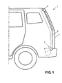
FIG. 1 is a side view of a vehicle rear portion to which a lock device of a closure for a vehicle according to an embodiment of the present invention is applied. -
FIG. 2 is an enlarged side view of the lock device (a sectional view taken along line B-B ofFIG. 3 ). -
FIG. 3 is a sectional view taken along line A-A ofFIG. 2 . -
FIG. 4 is an explanatory diagram of a testing method of the coefficient of friction. -
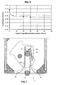
FIG. 5 is a chart of test results of the coefficient of friction using a ball test piece and a disk test piece. -
FIG. 6 is a chart of correlation of the content of tetrafluoroethylene and the coefficient of friction. -
FIG. 7 is a sectional view of another lock device, which corresponds toFIG. 3 . - Hereinafter, a lock device of a closure for a vehicle according to preferred embodiments of the present invention will be described.
- As shown in
FIG. 1 , anopening portion 2 for baggage loading or unloading and the like is provided at a rear portion of avehicle 1 of the present embodiment, and theopening portion 2 is configured to at least partly be opened or closed by a lift gate or hatchback door 4 that is provided so as to rotate or pivot around arotational axis 3, which is provided at or near an upper edge portion so as to extend substantially in a vehicle width direction. - At least one
striker 5 is attached to an intermediate portion (preferably substantially the center) of a lower edge portion of theopening portion 2 in the vehicle width direction, and at least onelatch 6 operative to engage with therespective striker 5 is provided an an intermediate portion (preferably substantially at the center) of a lower end portion of thelift gate 4 in the vehicle width direction. Thestriker 5 and thelatch 6 form part of alock device 7. - The
latch 6 comprises primarily, as shown inFIGS. 2 and3 , an upper orfirst case 11 and a lower orsecond case 12, and afork 13, afence block 14, aslide block 15, a stop rubber orresilient member 16, and a claw lever (not illustrated), which are disposed in an inner space at least partly enclosed by thecases - The
lower case 12 has agroove portion 12a that is formed so as to extend substantially in a vehicle longitudinal direction (or substantially an opening direction of the lift gate 4) and that is operative to receive thestriker 5 coming therein. - The
fork 13 is supported at asupport axis 17, one or both end portions of which are supported at the upper and/orlower cases support axis 17, and it has arecess portion 13a operative to engage with thestriker 5. Thefork 13 preferably is biased substantially in an engagement release direction (a clockwise direction inFIG. 3 ) by a spring or biasing member, not illustrated. - The
fence block 14 has agroove portion 14a that preferably is made from polyacetal (POM) and/or formed so as to extend substantially in the vehicle longitudinal direction and operative to receive thestriker 5 at least partly coming therein. The width of thegroove portion 14a is configured to be narrower than that of thegroove portion 12a of thelower case 12. - The slide block 15 (restriction portion) preferably is made from polyacetal (POM) and disposed in or at a
recess portion 14b formed at one side of thegroove portion 14a of thefence block 14 so as to be movable substantially in the opening direction of the lift gate 4 (the vehicle longitudinal direction in a plan view). Theslide block 15 is biased by at least one spring or biasingmember 18 in the opening direction a of thelift gate 4, and has a taper face at aside face 15a on the side of thegroove portion 14a preferably in such a manner that the distance between theside face 15a and aside face 14c of thefence block 14 becomes greater toward the vehicle rear. Thereby, as thestriker 5 at least partly comes into thegroove portion 14a of thefence block 14, it comes to be restricted by theside face 14c of thefence block 14 and side face 15a of theslide block 15. As a result, thelift gate 4 can be restrained from improperly shaking substantially in the vehicle width direction (direction of therotational axis 3 or a direction at an angle different from 0° or 180°, preferably substantially normal to the opening direction of the lift gate 4) at the vehicle traveling or the like. - The stop rubber or
resilient member 16 functions as an impact absorbent by contacting thestriker 5 of thelift gate 4 closing. - The claw lever is supported at the upper and/or
lower cases fork 12 in its engagement release direction (the clockwise direction inFIG. 3 ) at the engagement state of thefork 12 withstriker 5. Herein, the claw lever is configured to be linked to an operation of a passenger via a known mechanism, such as a bowden cable, which will not be described here. - According to the present embodiment, a low-friction material or substance having lubricant function preferably is provided at the
striker 5 and/or thefence block 14 and/or the slide block 15 (hereinafter, the first through fifth embodiments will be described specifically). Thereby, the coefficient of friction of contact portions of these members is made small. That is, the contact portions of thestriker 5 and thefence block 14 and/or the slide block 15 (restriction portion) are made properly slippery so as to smooth the relative movement between the lift gate 4 (closure) and theopening portion 2 of thevehicle 1 in a direction other than the direction of therotational axis 3. As a result, the responsiveness of deformation of the vehicle body when the outer force acts on the vehicle body can be improved. Accordingly, the stability of the vehicle when traveling, for example, improves. Herein, the low-friction material may be provided not only at the contact portions of the both members but at at least part of a surrounding portion of the contact portions or at an entire part of the members. - The above-described effect can be obtained effectively in a case where the lift gate 4 (closure) opens or closes the
rear opening portion 2 that may cause the deformation of the vehicle body easily when the outer force acts on. Herein, the closure of the present invention may include various types of closures, such as a side door that is provided at a passenger-ingress/egress opening portion of a vehicle side face, a lift gate that is provided at a baggage-loading/unloading opening portion of a vehicle rear face, a trunk lid that is provided at a trunk opening portion. - The low-friction material of the first embodiment is or comprises a coating film of resin that is at least partly provided on the surface of the striker. Thereby, the anticorrosive effect can be obtained in addition to the low-friction effect. Further, the coating is superior in productivity as a method for covering the surface of the member having a shape like the striker. Herein, various types of coating method, such as spraying, electro-deposition, immersion, may be applied.
- The coating film is comprised of at least one of resins of phenol, epoxy, polyamide, polyimide, polyamideimide, and tetrafluoroethylene. Thereby, the coating can be conducted or achieved easily. Herein, the best resin can be chosen depending on a specific structure of the latch structure (e.g., a contact load with the restriction portion).
- Herein, the coating film may contain a lubricant material. Thereby, the coefficient of friction between the striker and the restriction portion is made much lower, so the above-described effect can be further improved.
- The volume ratio of the lubricant material relative to the coating film may be preferably about 1 through about 50%. Thereby, the low-friction effect and the wear resistance of the coating film can be made compatible. A too-low volume ratio of the lubricant material may cause an insufficient low-friction effect. Meanwhile, the more that ratio increases, the more the low-friction effect improves. However, it has been determined that over 50% of the volume ratio, the improvement of the low-friction effect may not change substantially, but the wear resistance may decrease and become short instead.
- The thickness of the coating film may be preferably about 1 through about 300 µm. Thereby, the wear resistance and the economical efficiency of the coating film can be made compatible. It has been determined that a too-thin thickness of the coating film may cause an insufficient resistance because of a prompt wear. Meanwhile, the more the thickness increases, the more the resistance improves. However, it has been discovered that over the thickness of 300 µm, the resistance may become excessive, which may not be economical. Herein, the thickness of the coating film may be more preferably about 3 through about 100 µm. Thereby, the wear resistance and the economical efficiency of the coating film can be made compatible properly.
- The surface roughness of the coating film may be preferably less than Ra 5.0 µm. Thereby, any scratching or the like of the restriction portion can be prevented. A too-rough surface may scratch another member improperly. Herein, the surface roughness can be adjusted by a later-applied treatment. Herein, the surface roughness of the coating film may be more preferably less than Ra 2.5 µm. Thereby, any scratching or the like of the restriction portion can be prevented properly.
- In a case where the striker is made from steel, an anticorrosive treatment may be preferably applied to a base of the coating film. Thereby, the proper anticorrosive effect can be obtained, thereby improving the corrosion resistance. Various types of anticorrosive treatments, such as zincification, transformation, metal-piece dispersion treatment into a silicon-based inorganic binder, may be applied.
- The low-friction material of the second embodiment is comprised of at least one of nickel and chromium and a plating layer that contains a lubricant material that is comprised of at least one of molybdenum bisulfide, tungsten bisulfide, graphite, boron nitride, tetrafluoroethylene, and silicone resin. Thereby, the coefficient of friction with the contacting member can be made low. Further, the superior resistance can be expected more, compared to the resin coating film. The best low-friction material can be chosen depending on the specific structure of the latch structure (e.g., a contact load with the contacting member). Further, applying a nickel or chromium based plating to the entire surface of the striker can preferably provide the anticorrosive effect in addition to the low-friction effect.
- The volume ratio of the lubricant material relative to the plating layer may be preferably about 1 through about 50%. Thereby, the low-friction effect and the wear resistance of the plating layer can be made compatible. It has been determined that a too-low volume ratio of the lubricant material may cause an insufficient low-friction effect. Meanwhile, the more that ratio increases, the more the low-friction effect improves. However, it has been further determined that over about 50% of the volume ratio, the improvement of the low-friction effect may not change substantially, but the wear resistance may decrease and become short instead.
- The thickness of the plating layer may be preferably about 0.1 through about 200 µm. Thereby, the wear resistance and the economical efficiency of the plating layer can be made compatible. A too-thin thickness of the plating layer has been determined to possibly cause an insufficient resistance because of a prompt wear. Meanwhile, as the thickness increases, the resistance may improve. However, it has been further discovered that over the thickness of about 200 µm, the resistance may become excessive, which may not be economical. Herein, the thickness of the plating layer may be more preferably about 1 through about 50 µm. Thereby, the wear resistance and the economical efficiency of the plating layer can be made compatible properly.
- The surface roughness of the plating layer may be preferably less than Ra 2.0 µm. Thereby, any scratching or the like of the restriction portion can be prevented. A too-rough surface may scratch another member improperly. Herein, the surface roughness can be adjusted by a later-applied treatment. Herein, the surface roughness of the plating layer may be more preferably less than Ra 0.5 µm. Thereby, any scratching or the like of the restriction portion can be prevented properly.
- The low-friction material of the third embodiment is provided by at least one of manners of deposition, thermal spraying, film adhesion, and tube-inserting. Herein, the best method can be chosen depending on the specific structure of the latch structure (e.g., the contact load with the contacting member).
- The low-friction material containing a lubricant material of the fourth embodiment is provided on the surfaces of the
fence block 14 and the slide block 15 (restriction portion) of thelatch 6. Thereby, the coefficient of friction between thestriker 5 and the restriction portion can be made low. Herein, the coating film of the first embodiment and the film adhesion of the third embodiment may be used as the low-friction material. - The lubricant material of the fifth embodiment as the low-friction material is contained in a base material (base material of the restriction portion) of the
fence block 14 and theslide block 15 of thelatch 6. Thereby, the coefficient of friction between thestriker 5 and the restriction portion can be made much lower. For example, the base material is made from polyacetal and the low-friction material is comprised of at least one of silicone resin, molybdenum bisulfide, tungsten bisulfide, graphite, boron nitride, tetrafluoroethylene, and lubricating oil. Thereby, the mechanical properties and the proper low friction of the restriction portion can be provided. - The base material of the
fence block 14 and the slide block 15 (restriction portion) of thelatch 6 of the sixth embodiment preferably is made from a micro-crystal type POM (polyacetal) that has the low-friction effect. Thereby, the coefficient of friction can be made less than about 0.1 (friction-lowering means), so that the same effect as the low-friction material provided is obtained. - The coefficient of friction between the
striker 5 and thefence block 14 andslide block 15 was tested based on the following method. Herein, values of the coefficient of friction were obtained through a ball-on-disc test that using test pieces, not real products. - The test method will be described. As shown in
FIG. 4 , ball test pieces (samples) were made from the striker's material, and a disc test piece (sample) was made from the material of the restriction portion (thefence block 14 and the slide block 15). Each ball test piece comprises a steel ball having the diameter of 5/16 in. and the surface roughness of Ra 0.05 µm or less, and a low-friction material provided on the surface of the steel ball. - Three ball test pieces were fixed, without rotating, on an identical circumference with the diameter of 44 mm with constant intervals on the disc piece, and they were pressed against the disc test piece with the load of 100 N in total. Then, the disc test piece was rotated for one minute so that a slippery speed between the ball test pieces and the disc test piece can be 100 m/s. Here, the coefficient of friction was measured, and the average value of the coefficient of friction from during a test term was obtained. This friction test was conduced in an atmosphere of the temperature of 25ºC and the humidity of 40%. The test results are shown in
FIG. 5 . - At first, comparative samples will be described. In a
comparative sample 1, the ball test pieces of the steel ball with zincification chromate provided thereon and the disc test piece made from POM (standard grade) resin were used. In this case, the coefficient of friction was 0.131, which was greater than 0.1. Herein, the POM (standard grade) means the one that does not contain any lubricant material and has its coefficient of friction relative to the zincification chromate is 0.1 or more. - In a
comparative sample 2, the ball test pieces of the steel ball with zincification chromate and grease provided thereon and the disc test piece made from POM (standard grade) resin were used. In this case, the coefficient of friction was 0.092, which was less than 0.1. However, there are problems in that the surface is improperly sticky and some maintenance for anti-drying will be necessary due to drying or the like. - In a
comparative sample 3, the ball test pieces of the steel ball with nickel plating (normal one without any lubricant material) provided thereon and the disc test piece made from POM (standard grade) resin were used. In this case, the coefficient of friction was 0.115, which was greater than 0.1. - In a
comparative sample 4, the ball test pieces of the steel ball with chromium plating (normal one without any lubricant material) provided thereon and the disc test piece made from POM (standard grade) resin were used. In this case, the coefficient of friction was 0.135, which was greater than 0.1. - Accordingly, the coefficient of friction of the comparative samples 1 (zincification chromate), 3 (nickel plating) and 4 (chromium plating), other than the
comparative sample 2 with grease, was greater than 0.1. Herein, those samples with the coefficient of friction of 0.1 or less are considered to be the low friction. - Next, test samples will be described. Test samples 1 - 5 were samples in which the low-friction materials were provided on the ball test piece (striker's material).
- In a test sample 1 (corresponding to the first embodiment), the ball test pieces of the steel ball with epoxy resin, as the low-friction material, provided thereon and the disc test piece made from POM (standard grade) resin were used. In this case, the coefficient of friction was 0.0851, which showed the preferred low friction less than 0.1.
- In a test sample 2 (corresponding to the first embodiment), the ball test pieces of the steel ball with epoxy resin containing molybdenum bisulfide of 15 volume % coated thereon, as the low-friction material, and the disc test piece made from POM (standard grade) resin were used. In this case, the coefficient of friction was 0.076, which showed the low friction which is more than the
test sample 1. - In test samples 3 - 5 (corresponding to the second embodiment), the ball test pieces of the steel ball with nickel plating containing tetrafluoroethylene coated thereon, as the low-friction material, and the disc test piece made from POM (standard grade) resin were used. In these cases, the coefficient of friction was 0.081 for a case of tetrafluoroethylene of 5 volume % (test sample 3), the coefficient of friction was 0.074 for a case of tetrafluoroethylene of 20 volume % (test sample 4), and the coefficient of friction was 0.070 for a case of tetrafluoroethylene of 30 volume % (test sample 5), which all showed the low friction less than 0.1. Further, as shown in
FIG. 6 , the coefficient of friction became lower as the volume ratio of tetrafluoroethylene became smaller. Herein, in an area where the volume ratio of tetrafluoroethylene was less than approximately 5 volume %, the coefficient of friction became lower abruptly as the volume ratio of tetrafluoroethylene became greater. In an area where the volume ratio of tetrafluoroethylene was 5 volume % or greater, the lowering rate of the coefficient of friction became smaller and there occurred substantially no change in an area above 50 volume %. - Meanwhile,
test samples 6, 7 (corresponding to the fourth and fifth embodiments) are the one in which the low-friction material was provided at the disc test piece (fence block, slide block). In thetest sample 6, the ball test piece of the steel ball with zincification chromate provided thereon and the disc test piece made from POM (low friction grade (micro-crystal type)) resin were used. In this case, the coefficient of friction was 0.085, which showed the preferred low friction less than 0.1. - In the test sample 7 (corresponding to the sixth embodiment), the ball test piece of the steel ball with zincification chromate provided thereon and the disc test piece made from POM (low friction grade (silicon-addition type) resin were used. In this case, the coefficient of friction was 0.058, which showed the much lower friction preferably less than 0.1.
- Although the above-described embodiments show the example in which the
slide block 15 is provided at thelatch 6, the present invention can be applied to the lock device without the slide block. In a latch 6' of another modified lock device 7' shown inFIG. 7 , at one side of agroove portion 14a' of a fence block 14' is formed agroove portion 14c' that extends in substantially the same direction as thegroove portion 14a'. Further, an extending portion 19' that is formed integrally or unitarily with a stop rubber or resilient member 16' is provided so as to engage with thegroove portion 14c', and a striker 5' is restricted by both-side faces of thegroove portion 14a' of the fence block 14' with a resilient force of the extending portion 19'. In this case, the above-described various means for the low friction can be applied to the striker 5' and the fence block 14', so that the same function and effects can be provided as well. - Although the above-described embodiments show the examples in which the low-friction treatment is applied either the striker or the restriction portion, the low-friction treatment may be applied to the both. In this case the low-friction effect can be obtained more effectively.
- Also, there may be provided any types of smoothing means for smoothing the movement of the closure in a specified direction, including the above-described embodiments. According to the soothing means, the striker and the restriction portion can be made slippery in the direction other than the restriction direction, so that the above-described effects can be provided.
Claims (19)
- A lock device (7; 7') of a closure (4) for a vehicle (1), comprising:at least one striker (5; 5');at least one latch (6; 6') to engage with the striker (5; 5'), the latch (6; 6') including a restriction portion (14, 15; 14') operative to restrict a movement of a closure (4) in a direction of a rotational axis of the closure (4) by contacting the striker (5; 5'); andat least one smoothing means for smoothing a movement of the striker (5; 5') in a direction other than the direction of the rotational axis of the closure (4).
- The lock device (7; 7') of a closure (4) for a vehicle (1) of claim 1, wherein the smoothing means comprises a friction-lowering means for reducing the coefficient of friction between the striker (5; 5') and the restriction portion (14, 15; 14') of the latch (6; 6') less than 0.1.
- The lock device (7; 7') of a closure (4) for a vehicle (1) of any one of the preceding claims, wherein the closure (4) is a member that is provided so as to open and close a rear opening (2) of the vehicle (1).
- The lock device (7; 7') of a closure (4) for a vehicle (1) of any one of the preceding claims, wherein the smoothing means comprises a low-friction material having lubricant function that is provided at a contact portion of at least one of the striker (5; 5') and the restriction portion (14, 15; 14').
- The lock device (7; 7') of a closure (4) for a vehicle (1) of claim 4, wherein the low-friction material comprises a coating film of resin that is provided on a surface of the striker (5; 5').
- The lock device (7; 7') of a closure (4) for a vehicle (1) of claim 5, wherein the coating film is comprised of at least one of resins of phenol, epoxy, polyamide, polyimide, polyamideimide, and tetrafluoroethylene.
- The lock device (7; 7') of a closure (4) for a vehicle (1) of claim 5 or 6, wherein the coating film contains a lubricant material that is comprised of at least one of molybdenum bisulfide, tungsten bisulfide, graphite, boron nitride, tetrafluoroethylene, and silicone resin.
- The lock device (7; 7') of a closure (4) for a vehicle (1) of claim 7, wherein the volume ratio of the lubricant material relative to the coating film is about 1 through about 50%.
- The lock device (7; 7') of a closure (4) for a vehicle (1) of any one of claims 5 through 8, wherein the thickness of the coating film is about 1 through about 300 µm, preferably about 3 through about 100 µm.
- The lock device (7; 7') of a closure (4) for a vehicle (1) of claim 9, wherein a surface roughness of the coating film is less than Ra 5.0 µm, preferably less than Ra 2.5 µm.
- The lock device (7; 7') of a closure (4) for a vehicle (1) of any one of claims 5 through 10, wherein the striker (5; 5') is made from steel, and an anticorrosive treatment is applied to a base of the coating film.
- The lock device (7; 7') of a closure (4) for a vehicle (1) of any one of the preceding claims 4 to 11, wherein the low-friction material is comprised of at least one of nickel and chromium and a plating layer that contains a lubricant material that is comprised of at least one of molybdenum bisulfide, tungsten bisulfide, graphite, boron nitride, tetrafluoroethylene, and silicone resin.
- The lock device (7; 7') of a closure (4) for a vehicle (1) of claim 12, wherein the volume ratio of the lubricant material relative to the plating layer is 1 through 50%.
- The lock device (7; 7') of a closure (4) for a vehicle (1) of claims 12 or 13, wherein the thickness of the plating layer is 0.1 through 200 µm, preferably 1 through 50 µm.
- The lock device (7; 7') of a closure (4) for a vehicle (1) of any one of the preceding claims 12 to 14, wherein a surface roughness of the plating layer is less than Ra 2.0 µm, preferably less than Ra 0.5 µm.
- The lock device (7; 7') of a closure (4) for a vehicle (1) of any one of the preceding claims 4 to 15, wherein the low-friction material is provided by at least one of manners of deposition, thermal spraying, film adhesion, and tube-inserting.
- The lock device (7; 7') of a closure (4) for a vehicle (1) of any one of the preceding claims 2 to 16, wherein a lubricant material as the low-friction material is provided on a surface of a base material of the restriction portion (14, 15; 14') of the latch (6; 6').
- The lock device (7; 7') of a closure (4) for a vehicle (1) of any one of the claims 2 to 17, wherein a lubricant material as the low-friction material is contained in a base material of the restriction portion (14, 15; 14') of the latch (6; 6').
- The lock device (7; 7') of a closure (4) for a vehicle (1) of any one of the preceding claims, wherein a base material of the restriction portion of the latch (6; 6') is made from polyacetal, and the low-friction material is comprised of at least one of silicone resin, molybdenum bisulfide, tungsten bisulfide, graphite, boron nitride, tetrafluoroethylene, and lubricating oil.
Applications Claiming Priority (1)
| Application Number | Priority Date | Filing Date | Title |
|---|---|---|---|
| JP2007078388A JP2008238847A (en) | 2007-03-26 | 2007-03-26 | Locking device for vehicle opening / closing body |
Publications (1)
| Publication Number | Publication Date |
|---|---|
| EP1975352A1 true EP1975352A1 (en) | 2008-10-01 |
Family
ID=39522417
Family Applications (1)
| Application Number | Title | Priority Date | Filing Date |
|---|---|---|---|
| EP20080004023 Withdrawn EP1975352A1 (en) | 2007-03-26 | 2008-03-04 | Lock device of closure for vehicle |
Country Status (4)
| Country | Link |
|---|---|
| US (1) | US20080236219A1 (en) |
| EP (1) | EP1975352A1 (en) |
| JP (1) | JP2008238847A (en) |
| CN (1) | CN101275449A (en) |
Cited By (2)
| Publication number | Priority date | Publication date | Assignee | Title |
|---|---|---|---|---|
| RU2399737C1 (en) * | 2009-02-16 | 2010-09-20 | Алексей Николаевич Миронов | Electromechanical lock for transport vehicle |
| WO2016058589A1 (en) * | 2014-10-15 | 2016-04-21 | Kiekert Ag | Motor vehicle door lock and associated method for producing such a motor vehicle door lock |
Families Citing this family (6)
| Publication number | Priority date | Publication date | Assignee | Title |
|---|---|---|---|---|
| US20110133491A1 (en) * | 2009-12-08 | 2011-06-09 | Perkins Donald M | Vehicle door latch |
| DE102010011716A1 (en) * | 2009-12-24 | 2011-06-30 | Kiekert AG, 42579 | Method for producing lock holders and lock holders |
| US8389129B2 (en) * | 2010-07-09 | 2013-03-05 | Climax Engineered Materials, Llc | Low-friction surface coatings and methods for producing same |
| CN102560343A (en) * | 2010-12-23 | 2012-07-11 | 鸿富锦精密工业(深圳)有限公司 | Covering part and manufacturing method thereof |
| DE102011084960A1 (en) * | 2011-10-21 | 2013-04-25 | Kiekert Ag | Motor vehicle lock with independent refatting |
| JP7780944B2 (en) * | 2021-12-23 | 2025-12-05 | ミネベアミツミ株式会社 | Vehicle power supply device and door latch device |
Citations (7)
| Publication number | Priority date | Publication date | Assignee | Title |
|---|---|---|---|---|
| US4165112A (en) | 1977-06-04 | 1979-08-21 | Arn. Kiekert Sohne | Motor-vehicle door latch |
| US4466645A (en) | 1982-03-22 | 1984-08-21 | Ohi Seisakusho Co., Ltd. | Automobile door latch striker |
| US4981313A (en) | 1988-03-28 | 1991-01-01 | Mitsui Kinzoku Kogyo Kabushiki Kaisha | Striker for automotive door locking apparatus |
| GB2251025A (en) | 1990-11-27 | 1992-06-24 | Mitsui Mining & Smelting Co | Bump stop for vehicle door striker |
| US5348355A (en) | 1991-12-11 | 1994-09-20 | Mazda Motor Corporation | Automotive engine hood latch mechanism |
| DE19824466A1 (en) | 1998-05-30 | 1999-12-02 | Volkswagen Ag | Car door etc lock closure with twist and closing bolts |
| GB2352002A (en) | 1999-07-02 | 2001-01-17 | Ford Global Tech Inc | Resin-bonded solid-film-lubricant coated hood latch |
Family Cites Families (18)
| Publication number | Priority date | Publication date | Assignee | Title |
|---|---|---|---|---|
| US1318382A (en) * | 1919-10-14 | Ahtibattle doob-latch | ||
| US1990141A (en) * | 1931-01-16 | 1935-02-05 | Mitchell Specialty Company | Door retainer |
| US2156874A (en) * | 1938-09-14 | 1939-05-02 | Rudolph I Schonitzer | Door holding and door control mechanism |
| US2310550A (en) * | 1940-01-22 | 1943-02-09 | John H Roethel | Door latch |
| US2427511A (en) * | 1944-02-18 | 1947-09-16 | Roethel Engineering Corp | Door latch |
| US2499165A (en) * | 1949-02-10 | 1950-02-28 | John H Roethel | Latch bolt keeper |
| US2613097A (en) * | 1949-04-30 | 1952-10-07 | Burnie J Craig | Dovetail construction |
| US2629621A (en) * | 1949-12-17 | 1953-02-24 | Roethel Engineering Corp | Latch bolt keeper |
| US2629622A (en) * | 1949-12-23 | 1953-02-24 | Roethel Engineering Corp | Latch bolt keeper |
| US2706128A (en) * | 1950-01-28 | 1955-04-12 | Roethel Engineering Corp | Door lock |
| US2679420A (en) * | 1950-08-19 | 1954-05-25 | Jr William G Crockett | Automobile door latch |
| US2914352A (en) * | 1957-08-23 | 1959-11-24 | John H Roethel | Door lock mechanism |
| GB1114924A (en) * | 1964-07-10 | 1968-05-22 | Wilmot Breeden Ltd | Improvements in or relating to vehicle door fastening devices |
| DE3740757A1 (en) * | 1987-12-02 | 1989-06-22 | Kiekert Gmbh Co Kg | MOTOR VEHICLE DOOR LOCK WITH LOCKING KEY AND LOCK |
| CA1320238C (en) * | 1988-03-14 | 1993-07-13 | Shinjiro Yamada | Door lock device for vehicle |
| CA2015445C (en) * | 1989-04-27 | 1998-08-18 | Yoshikazu Hamada | Lock device for vehicle |
| GB2282843B (en) * | 1993-10-13 | 1996-03-20 | Rockwell Body & Chassis Syst | Latch assembly |
| JP2729571B2 (en) * | 1993-11-30 | 1998-03-18 | 株式会社大井製作所 | Door lock device |
-
2007
- 2007-03-26 JP JP2007078388A patent/JP2008238847A/en not_active Abandoned
-
2008
- 2008-01-29 US US12/021,433 patent/US20080236219A1/en not_active Abandoned
- 2008-03-04 EP EP20080004023 patent/EP1975352A1/en not_active Withdrawn
- 2008-03-05 CN CNA2008100835301A patent/CN101275449A/en active Pending
Patent Citations (7)
| Publication number | Priority date | Publication date | Assignee | Title |
|---|---|---|---|---|
| US4165112A (en) | 1977-06-04 | 1979-08-21 | Arn. Kiekert Sohne | Motor-vehicle door latch |
| US4466645A (en) | 1982-03-22 | 1984-08-21 | Ohi Seisakusho Co., Ltd. | Automobile door latch striker |
| US4981313A (en) | 1988-03-28 | 1991-01-01 | Mitsui Kinzoku Kogyo Kabushiki Kaisha | Striker for automotive door locking apparatus |
| GB2251025A (en) | 1990-11-27 | 1992-06-24 | Mitsui Mining & Smelting Co | Bump stop for vehicle door striker |
| US5348355A (en) | 1991-12-11 | 1994-09-20 | Mazda Motor Corporation | Automotive engine hood latch mechanism |
| DE19824466A1 (en) | 1998-05-30 | 1999-12-02 | Volkswagen Ag | Car door etc lock closure with twist and closing bolts |
| GB2352002A (en) | 1999-07-02 | 2001-01-17 | Ford Global Tech Inc | Resin-bonded solid-film-lubricant coated hood latch |
Cited By (2)
| Publication number | Priority date | Publication date | Assignee | Title |
|---|---|---|---|---|
| RU2399737C1 (en) * | 2009-02-16 | 2010-09-20 | Алексей Николаевич Миронов | Electromechanical lock for transport vehicle |
| WO2016058589A1 (en) * | 2014-10-15 | 2016-04-21 | Kiekert Ag | Motor vehicle door lock and associated method for producing such a motor vehicle door lock |
Also Published As
| Publication number | Publication date |
|---|---|
| US20080236219A1 (en) | 2008-10-02 |
| JP2008238847A (en) | 2008-10-09 |
| CN101275449A (en) | 2008-10-01 |
Similar Documents
| Publication | Publication Date | Title |
|---|---|---|
| US20080236219A1 (en) | Lock device of closure for vehicle | |
| US5348355A (en) | Automotive engine hood latch mechanism | |
| US12024930B2 (en) | Closure latch assembly with latch mechanism having roller pawl assembly | |
| KR101607470B1 (en) | Process for reduction of friction | |
| CN1206122C (en) | Automobile door limiter | |
| US8240722B2 (en) | Stop armature for aircraft doors | |
| JP4511746B2 (en) | Releasable door stop for cars | |
| US20140292000A1 (en) | Apparatus and method for preventing undesired engagement of hold open lever in a latch | |
| EP3073036B1 (en) | Door latch device for vehicle | |
| US20070040392A1 (en) | Door checker for automobile | |
| JP5382542B2 (en) | Check link device | |
| US7059016B2 (en) | Automotive door check assemblies | |
| US11608661B2 (en) | Motor vehicle door lock | |
| US20140318023A1 (en) | Strain distribution check link assembly | |
| US4472857A (en) | Stop device, in particular for an automotive vehicle door | |
| EP0418783B1 (en) | Vehicle door check mechanism | |
| US8172299B2 (en) | Compartment door with force and effort control | |
| US20140239648A1 (en) | Motor vehicle lock with automatic relubrication | |
| JP5003408B2 (en) | Guide rollers for vehicle sliding doors | |
| EP4034398B1 (en) | Roller mechanism with limited rotation | |
| RU2562032C2 (en) | Carrier opening part lock and rotary lug | |
| US12312847B2 (en) | Door hinge with integrated door check | |
| US20040262828A1 (en) | Device to provide initial pop-up of an automotive deck lid via a gas spring | |
| US10017970B2 (en) | Motor vehicle door latch device | |
| US20250376877A1 (en) | Closure latch assembly with latch mechanism having roller pawl assembly |
Legal Events
| Date | Code | Title | Description |
|---|---|---|---|
| PUAI | Public reference made under article 153(3) epc to a published international application that has entered the european phase |
Free format text: ORIGINAL CODE: 0009012 |
|
| AK | Designated contracting states |
Kind code of ref document: A1 Designated state(s): AT BE BG CH CY CZ DE DK EE ES FI FR GB GR HR HU IE IS IT LI LT LU LV MC MT NL NO PL PT RO SE SI SK TR |
|
| AX | Request for extension of the european patent |
Extension state: AL BA MK RS |
|
| 17P | Request for examination filed |
Effective date: 20090326 |
|
| 17Q | First examination report despatched |
Effective date: 20090512 |
|
| AKX | Designation fees paid |
Designated state(s): DE |
|
| STAA | Information on the status of an ep patent application or granted ep patent |
Free format text: STATUS: THE APPLICATION IS DEEMED TO BE WITHDRAWN |
|
| 18D | Application deemed to be withdrawn |
Effective date: 20110726 |