EP1975309A1 - Metallic cord, rubber/cord composite object, and pneumatic tire obtained using the same - Google Patents
Metallic cord, rubber/cord composite object, and pneumatic tire obtained using the same Download PDFInfo
- Publication number
- EP1975309A1 EP1975309A1 EP06833767A EP06833767A EP1975309A1 EP 1975309 A1 EP1975309 A1 EP 1975309A1 EP 06833767 A EP06833767 A EP 06833767A EP 06833767 A EP06833767 A EP 06833767A EP 1975309 A1 EP1975309 A1 EP 1975309A1
- Authority
- EP
- European Patent Office
- Prior art keywords
- rubber
- plated layer
- cord
- zinc
- layer
- Prior art date
- Legal status (The legal status is an assumption and is not a legal conclusion. Google has not performed a legal analysis and makes no representation as to the accuracy of the status listed.)
- Granted
Links
Images


Classifications
-
- B—PERFORMING OPERATIONS; TRANSPORTING
- B60—VEHICLES IN GENERAL
- B60C—VEHICLE TYRES; TYRE INFLATION; TYRE CHANGING; CONNECTING VALVES TO INFLATABLE ELASTIC BODIES IN GENERAL; DEVICES OR ARRANGEMENTS RELATED TO TYRES
- B60C9/00—Reinforcements or ply arrangement of pneumatic tyres
- B60C9/0007—Reinforcements made of metallic elements, e.g. cords, yarns, filaments or fibres made from metal
-
- D—TEXTILES; PAPER
- D07—ROPES; CABLES OTHER THAN ELECTRIC
- D07B—ROPES OR CABLES IN GENERAL
- D07B1/00—Constructional features of ropes or cables
- D07B1/06—Ropes or cables built-up from metal wires, e.g. of section wires around a hemp core
-
- B—PERFORMING OPERATIONS; TRANSPORTING
- B60—VEHICLES IN GENERAL
- B60C—VEHICLE TYRES; TYRE INFLATION; TYRE CHANGING; CONNECTING VALVES TO INFLATABLE ELASTIC BODIES IN GENERAL; DEVICES OR ARRANGEMENTS RELATED TO TYRES
- B60C9/00—Reinforcements or ply arrangement of pneumatic tyres
-
- B—PERFORMING OPERATIONS; TRANSPORTING
- B60—VEHICLES IN GENERAL
- B60C—VEHICLE TYRES; TYRE INFLATION; TYRE CHANGING; CONNECTING VALVES TO INFLATABLE ELASTIC BODIES IN GENERAL; DEVICES OR ARRANGEMENTS RELATED TO TYRES
- B60C9/00—Reinforcements or ply arrangement of pneumatic tyres
- B60C9/18—Structure or arrangement of belts or breakers, crown-reinforcing or cushioning layers
- B60C9/20—Structure or arrangement of belts or breakers, crown-reinforcing or cushioning layers built-up from rubberised plies each having all cords arranged substantially parallel
- B60C9/2003—Structure or arrangement of belts or breakers, crown-reinforcing or cushioning layers built-up from rubberised plies each having all cords arranged substantially parallel characterised by the materials of the belt cords
- B60C9/2006—Structure or arrangement of belts or breakers, crown-reinforcing or cushioning layers built-up from rubberised plies each having all cords arranged substantially parallel characterised by the materials of the belt cords consisting of steel cord plies only
-
- C—CHEMISTRY; METALLURGY
- C23—COATING METALLIC MATERIAL; COATING MATERIAL WITH METALLIC MATERIAL; CHEMICAL SURFACE TREATMENT; DIFFUSION TREATMENT OF METALLIC MATERIAL; COATING BY VACUUM EVAPORATION, BY SPUTTERING, BY ION IMPLANTATION OR BY CHEMICAL VAPOUR DEPOSITION, IN GENERAL; INHIBITING CORROSION OF METALLIC MATERIAL OR INCRUSTATION IN GENERAL
- C23C—COATING METALLIC MATERIAL; COATING MATERIAL WITH METALLIC MATERIAL; SURFACE TREATMENT OF METALLIC MATERIAL BY DIFFUSION INTO THE SURFACE, BY CHEMICAL CONVERSION OR SUBSTITUTION; COATING BY VACUUM EVAPORATION, BY SPUTTERING, BY ION IMPLANTATION OR BY CHEMICAL VAPOUR DEPOSITION, IN GENERAL
- C23C10/00—Solid state diffusion of only metal elements or silicon into metallic material surfaces
- C23C10/02—Pretreatment of the material to be coated
-
- C—CHEMISTRY; METALLURGY
- C23—COATING METALLIC MATERIAL; COATING MATERIAL WITH METALLIC MATERIAL; CHEMICAL SURFACE TREATMENT; DIFFUSION TREATMENT OF METALLIC MATERIAL; COATING BY VACUUM EVAPORATION, BY SPUTTERING, BY ION IMPLANTATION OR BY CHEMICAL VAPOUR DEPOSITION, IN GENERAL; INHIBITING CORROSION OF METALLIC MATERIAL OR INCRUSTATION IN GENERAL
- C23C—COATING METALLIC MATERIAL; COATING MATERIAL WITH METALLIC MATERIAL; SURFACE TREATMENT OF METALLIC MATERIAL BY DIFFUSION INTO THE SURFACE, BY CHEMICAL CONVERSION OR SUBSTITUTION; COATING BY VACUUM EVAPORATION, BY SPUTTERING, BY ION IMPLANTATION OR BY CHEMICAL VAPOUR DEPOSITION, IN GENERAL
- C23C28/00—Coating for obtaining at least two superposed coatings either by methods not provided for in a single one of groups C23C2/00 - C23C26/00 or by combinations of methods provided for in subclasses C23C and C25C or C25D
- C23C28/02—Coating for obtaining at least two superposed coatings either by methods not provided for in a single one of groups C23C2/00 - C23C26/00 or by combinations of methods provided for in subclasses C23C and C25C or C25D only coatings only including layers of metallic material
- C23C28/021—Coating for obtaining at least two superposed coatings either by methods not provided for in a single one of groups C23C2/00 - C23C26/00 or by combinations of methods provided for in subclasses C23C and C25C or C25D only coatings only including layers of metallic material including at least one metal alloy layer
-
- C—CHEMISTRY; METALLURGY
- C23—COATING METALLIC MATERIAL; COATING MATERIAL WITH METALLIC MATERIAL; CHEMICAL SURFACE TREATMENT; DIFFUSION TREATMENT OF METALLIC MATERIAL; COATING BY VACUUM EVAPORATION, BY SPUTTERING, BY ION IMPLANTATION OR BY CHEMICAL VAPOUR DEPOSITION, IN GENERAL; INHIBITING CORROSION OF METALLIC MATERIAL OR INCRUSTATION IN GENERAL
- C23C—COATING METALLIC MATERIAL; COATING MATERIAL WITH METALLIC MATERIAL; SURFACE TREATMENT OF METALLIC MATERIAL BY DIFFUSION INTO THE SURFACE, BY CHEMICAL CONVERSION OR SUBSTITUTION; COATING BY VACUUM EVAPORATION, BY SPUTTERING, BY ION IMPLANTATION OR BY CHEMICAL VAPOUR DEPOSITION, IN GENERAL
- C23C28/00—Coating for obtaining at least two superposed coatings either by methods not provided for in a single one of groups C23C2/00 - C23C26/00 or by combinations of methods provided for in subclasses C23C and C25C or C25D
- C23C28/02—Coating for obtaining at least two superposed coatings either by methods not provided for in a single one of groups C23C2/00 - C23C26/00 or by combinations of methods provided for in subclasses C23C and C25C or C25D only coatings only including layers of metallic material
- C23C28/023—Coating for obtaining at least two superposed coatings either by methods not provided for in a single one of groups C23C2/00 - C23C26/00 or by combinations of methods provided for in subclasses C23C and C25C or C25D only coatings only including layers of metallic material only coatings of metal elements only
- C23C28/025—Coating for obtaining at least two superposed coatings either by methods not provided for in a single one of groups C23C2/00 - C23C26/00 or by combinations of methods provided for in subclasses C23C and C25C or C25D only coatings only including layers of metallic material only coatings of metal elements only with at least one zinc-based layer
-
- C—CHEMISTRY; METALLURGY
- C25—ELECTROLYTIC OR ELECTROPHORETIC PROCESSES; APPARATUS THEREFOR
- C25D—PROCESSES FOR THE ELECTROLYTIC OR ELECTROPHORETIC PRODUCTION OF COATINGS; ELECTROFORMING; APPARATUS THEREFOR
- C25D5/00—Electroplating characterised by the process; Pretreatment or after-treatment of workpieces
- C25D5/10—Electroplating with more than one layer of the same or of different metals
-
- C—CHEMISTRY; METALLURGY
- C25—ELECTROLYTIC OR ELECTROPHORETIC PROCESSES; APPARATUS THEREFOR
- C25D—PROCESSES FOR THE ELECTROLYTIC OR ELECTROPHORETIC PRODUCTION OF COATINGS; ELECTROFORMING; APPARATUS THEREFOR
- C25D5/00—Electroplating characterised by the process; Pretreatment or after-treatment of workpieces
- C25D5/48—After-treatment of electroplated surfaces
- C25D5/50—After-treatment of electroplated surfaces by heat-treatment
-
- C—CHEMISTRY; METALLURGY
- C25—ELECTROLYTIC OR ELECTROPHORETIC PROCESSES; APPARATUS THEREFOR
- C25D—PROCESSES FOR THE ELECTROLYTIC OR ELECTROPHORETIC PRODUCTION OF COATINGS; ELECTROFORMING; APPARATUS THEREFOR
- C25D7/00—Electroplating characterised by the article coated
- C25D7/06—Wires; Strips; Foils
- C25D7/0607—Wires
-
- D—TEXTILES; PAPER
- D07—ROPES; CABLES OTHER THAN ELECTRIC
- D07B—ROPES OR CABLES IN GENERAL
- D07B1/00—Constructional features of ropes or cables
- D07B1/06—Ropes or cables built-up from metal wires, e.g. of section wires around a hemp core
- D07B1/0606—Reinforcing cords for rubber or plastic articles
- D07B1/0666—Reinforcing cords for rubber or plastic articles the wires being characterised by an anti-corrosive or adhesion promoting coating
-
- D—TEXTILES; PAPER
- D07—ROPES; CABLES OTHER THAN ELECTRIC
- D07B—ROPES OR CABLES IN GENERAL
- D07B2201/00—Ropes or cables
- D07B2201/20—Rope or cable components
- D07B2201/2001—Wires or filaments
- D07B2201/201—Wires or filaments characterised by a coating
- D07B2201/2011—Wires or filaments characterised by a coating comprising metals
-
- D—TEXTILES; PAPER
- D07—ROPES; CABLES OTHER THAN ELECTRIC
- D07B—ROPES OR CABLES IN GENERAL
- D07B2205/00—Rope or cable materials
- D07B2205/30—Inorganic materials
- D07B2205/3021—Metals
- D07B2205/3085—Alloys, i.e. non ferrous
- D07B2205/3089—Brass, i.e. copper (Cu) and zinc (Zn) alloys
-
- D—TEXTILES; PAPER
- D07—ROPES; CABLES OTHER THAN ELECTRIC
- D07B—ROPES OR CABLES IN GENERAL
- D07B2401/00—Aspects related to the problem to be solved or advantage
- D07B2401/20—Aspects related to the problem to be solved or advantage related to ropes or cables
- D07B2401/202—Environmental resistance
- D07B2401/2035—High temperature resistance
-
- D—TEXTILES; PAPER
- D07—ROPES; CABLES OTHER THAN ELECTRIC
- D07B—ROPES OR CABLES IN GENERAL
- D07B2401/00—Aspects related to the problem to be solved or advantage
- D07B2401/20—Aspects related to the problem to be solved or advantage related to ropes or cables
- D07B2401/2095—Improving filler wetting respectively or filler adhesion
-
- D—TEXTILES; PAPER
- D07—ROPES; CABLES OTHER THAN ELECTRIC
- D07B—ROPES OR CABLES IN GENERAL
- D07B2501/00—Application field
- D07B2501/20—Application field related to ropes or cables
- D07B2501/2046—Tire cords
-
- D—TEXTILES; PAPER
- D07—ROPES; CABLES OTHER THAN ELECTRIC
- D07B—ROPES OR CABLES IN GENERAL
- D07B2501/00—Application field
- D07B2501/20—Application field related to ropes or cables
- D07B2501/2076—Power transmissions
Definitions
- the present invention relates to a metal cord and a rubber-cord complex in which an adhesion reaction layer formed between a rubber and a brass plated layer of a plated element wire is specified to thereby suppress deterioration in adhesiveness between the plated wire and the rubber under a wet heat environment, and a pneumatic tire using the complex.
- a metal cord As a reinforcing element for rubber products such as pneumatic tires, hoses and industrial belts, a metal cord has been popularly used from the viewpoints of good reinforcing effect and the like.
- a rubber-cord complex such as a rubber product reinforced with such a metal cord
- the surface of element wires of the cord is plated with brass containing copper and zinc in order to enhance the adhesive property of the metal cord to the rubber.
- this brass plating is performed in such a manner as sequentially forming a copper plated layer and a zinc plated layer on the surface of an element wire and then subjecting them to thermal diffusion to give an alloy of the two metals.
- a conventional brass plating has a good adhesive property in an initial stage after the vulcanization (initial adhesive property), it tends to be poor in wet heat adhesive property such that the adhesive property decreases under a wet heat environment at high temperature and high humidity and the brass plating is more likely to separate from the rubber. It is effective for improving the wet heat adhesive property to add an organocobalt salt to the rubber.
- the organocobalt salt is expensive, and has a property of making an unvulcanized rubber apt to deteriorate or thermally deteriorate. Hence the amount of the organocobalt salt to be incorporated is limited, so a sufficient increase in wet heat adhesive property is not achieved thereby.
- the present inventors conducted an intensive study and, as a result, they have found that the adhesive property under the wet heat environment can be exhibited on a higher level as compared with a conventionally achieved adhesive property when the state of irregularity of the interface between the adhesion reaction layer and the rubber and the average thickness of the adhesion reaction layer fall within specific ranges.
- a primary object of the present invention is to provide a rubber-cord complex having a wet heat adhesive property improved basically by specifying the state of irregularity of the interface between the adhesion reaction layer and the rubber and the average thickness of the adhesion reaction layer.
- a second object of the present invention is to provide a metal cord suitable for use in the rubber-cord complex and capable of improving its wet heat adhesive property to a rubber vulcanized and adhered thereto.
- a third object of the present invention is to provide a pneumatic tire with its durability improved by the use of the rubber-cord complex as mentioned above.
- the present invention as claimed in claim 1 is directed to a rubber-cord complex obtained by vulcanizing a rubber to adhere it to a metal cord comprising a drawn plated wire prepared by providing a plated layer of brass containing copper and zinc on the surface of a metal wire and drawing the resulting plated wire, wherein:
- the invention as claimed in claim 5 is directed to a metal cord for use in the rubber-cord complex according to claims 1 to 3, wherein the brass plated layer is formed by thermal diffusion of a copper plated layer and a zinc plated layer formed by plating in layers on a metal wire, in which the copper plated layer is formed by plating at a current density of 15 to 25 A/dm 2 , the zinc plated layer is formed by plating at a current density of 40 to 60 A/dm 2 , and the thermal diffusion is conducted by a low temperature diffusion at a temperature of 500 to 550°C.
- the invention as claimed in claim 6 is directed to a metal cord for use in the rubber-cord complex according to claims 1 to 3, wherein the brass plated layer is formed by thermal diffusion of a copper plated layer and a plated layer of a zinc alloy selected from a zinc-nickel alloy and a zinc-cobalt alloy, the layers being formed in layers on a metal wire, in which the copper plated layer is formed by plating at a current density of 15 to 25 A/dm 2 , the zinc alloy plated layer is formed by plating at a current density of 40 to 60 A/dm 2 , and the thermal diffusion is conducted by a low temperature diffusion at a temperature of 500 to 550°C.
- the invention as claimed in claim 7 is directed to a pneumatic tire in which the rubber-cord complex according to claims 1 to 4 is used as a ply for tire reinforcement.
- the irregularity of the interface between a rubber and an adhesion reaction layer in which sulfur in the rubber and copper in a brass plated layer bond to each other by a cross-linking reaction is increased and complicated such that the fractal dimension of the interface falls within the range of 1.001 to 1.300.
- the average thickness of the adhesion reaction layer is properly secured.
- the bonding force to the rubber at the interface of the adhesion reaction layer can be sufficiently increased and, in addition, increase in strength of the adhesion reaction layer itself can be achieved.
- improvement in wet heat adhesive property between the rubber and the cord can be achieved.
- FIG. 1 is a cross sectional view showing a pneumatic tire in which a rubber-cord complex of the present invention is used as a ply for tire reinforcement.
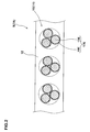
- FIG. 2 is a cross sectional view showing the above-mentioned ply which is the rubber-cord complex.
- a pneumatic tire 1 shown in this example is a radial tire for passenger cars, and it includes a carcass 6 extending from a tread portion 2 to bead cores 5 in bead portions 4 through sidewall portions 3, and a belt layer 7 arranged radially outward of the carcass 6 in the tread portion 2.
- the carcass 6 is formed of one or more carcass plies 6A having carcass cords arranged, for example, at an angle of 75 to 90 degrees with respect to the circumferential direction of the tire.
- the carcass ply 6A comprises a ply main body portion 6a extending between the bead cores 5, 5, and ply turnup portions 6b that are turned up around the bead cores 5 from the inside to the outside at each end of the ply main body portion 6a.
- a bead apex rubber 8 extending radially outwardly from the bead core 5 in a tapered manner is disposed between the ply main body portion 6a and the ply turnup portion 6b, whereby a portion from the bead portion 4 to the sidewall portion 3 is reinforced.
- the belt layer 7 comprises two or more belt plies, two belt plies 7A, 7B in this example, having belt cords arranged at an angle of 10 to 45 degrees with respect to the circumferential direction of the tire.
- the belt plies are stacked so that the belt cords in one ply intersects with those in another belt ply to thereby enhance the belt rigidity so as to firmly reinforce the tread portion 2.
- the rubber-cord complex 9 of the present invention is adopted to the belt plies 7A, 7B out of the plies for tire reinforcement including the carcass ply 6A and the belt plies 7A, 7B.
- the rubber-cord complex 9 is composed of a cord array body 11 that metal cords 10 as belt cords are arranged mutually in parallel, and a rubber 12 for topping formed by covering the surface and back of the cord array body 11 with the rubber and subjecting the rubber to vulcanization-bonding to the cord array body.
- the "vulcanization-bonding" is achieved by vulcanization heat applied when an unvulcanized green tire is vulcanized and molded in a mold.
- the rubber 12 for topping can be suitably used conventional rubbers for use in tires, in which sulfur is incorporated in a rubber base material. Besides sulfur, known additives, e.g., a vulcanization accelerator and a vulcanization acceleration assistant, are selectively used for the rubber 12 in order to obtain required physical properties of the rubber.
- known additives e.g., a vulcanization accelerator and a vulcanization acceleration assistant
- the rubber base material are preferably used diene rubbers such as natural rubber, isoprene rubber, butadiene rubber and styrene/butadiene rubber. The diene rubbers are used alone or in the form of a blend of two or more rubbers. Table 1 shows an example of a rubber composition for the rubber 12. The composition dose not contain any organocobalt salt as mentioned above.
- the metal cord 10 is composed of at least one drawn plated wire 17E obtained by forming a brass plated layer 16 on the surface of a metal element wire 15 and drawing the resulting plated wire.
- the wires 17E are twisted in a known twisting structure such as bundle-twisting or layer-twisting.
- a metal cord 10 having a 1 ⁇ 3 structure where three plated wires 17E are twisted together is shown in FIG. 2 .
- the brass plated layer 16 is a brass-based plating containing copper and zinc as main components.
- a binary alloy plating comprised of copper and zinc, or a ternary alloy plating containing, besides copper and zinc, cobalt or nickel as a third metal.
- the content of copper is in the range of 60 to 80 parts by weight and the content of zinc is in the range of 40 to 20 parts by weight, with respect to 100 parts by weight of the plating.
- the content of cobalt is in the range of 0.1 to 5.0 parts by weight and the content of nickel is in the range of 1.0 to 10.0 parts by weight.
- the brass plated layer 16 made of the binary alloy plating is formed in such a manner that primary plated layers 20, i.e., a copper plated layer 20A and a zinc plated layer 20B, are formed one after another on the surface of a metal element wire 15, and then subjected to thermal diffusion to alloy the both metals (copper and zinc).
- Numeral 17A denotes a plated element wire prior to drawing
- numeral 17E denotes a plated wire after drawing.
- the copper plated layer 20A can be formed by electroplating treatment in a copper plating bath such as a copper pyrophosphate bath or a copper sulfate bath.
- the zinc plated layer 20B can be formed by electroplating treatment in a zinc plating bath such as a zinc sulfate bath. Further, the thermal diffusion is performed by thermally treating an element wire 15 having the copper plated layer 20A and the zinc plated layer 20B in a heating apparatus.
- a third metal plated layer 20C is formed by electroplating treatment in a third metal bath which is a cobalt bath or a nickel bath, and the three layers are then thermally diffused and alloyed.
- the order of formation of respective primary plated layers is not particularly restricted.
- the element wire 15 is made of steel, it is not preferable to firstly form the zinc plated layer 20B from the viewpoint of the plating peeling property since a hard and fragile alloy phase of iron and zinc is produced on the surface of the element wire 15. Further, diffusion tends to occur with difficulty between the copper plated layer 20A and the third metal plated layer 20C as compared with an interface between other plated layers. Therefore, it is preferable not to dispose the copper plated layer 20A and the third metal plated layer 20C adjacently to each other.
- the order of the copper plated layer 20A and the zinc plated layer 20B is preferred, and in the case of the ternary alloy plating, the order of the copper plated layer 20A, the zinc plated layer 20B and the third metal plated layer 20C is preferred.
- the plated wire 17A is subjected to a known wire drawing process to give a plated wire 17E drawn to a desired diameter.
- Numeral 16E denotes a brass plated layer in the drawn plated wire 17E
- numeral 15E denotes a wire 15 in the drawn plated wire 17E.
- another method for forming the brass plated layer 16 made of the ternary alloy plating is a method wherein, as shown in FIG. 3(C) , the copper plated layer 20A is firstly formed on the surface of the metal wire 15 and, thereafter, a plated layer 20D of an alloy of zinc and nickel or an alloy of zinc and cobalt is formed on the copper plated layer 20A. Subsequently, the plated layers are subjected to thermal diffusion to give the brass plated layer 16.
- This alloy plated layer 20D can be formed by electroplating treatment in an alloy bath containing zinc sulfate and nickel or an alloy bath containing zinc sulfate and cobalt.
- the content of the third metal in the external surface after the thermal diffusion decreases relatively as compared with the case of forming the third metal plated layer 20C as the outermost layer (the case shown in FIG. 3(B) ). It is therefore possible to improve the drawing processability in the wire drawing step.
- the adhesive property between the brass plated layer 16E and the rubber 12 is exhibited by formation of an adhesion reaction layer 25 at an interface between the brass plated layer 16E and the rubber 12, as shown in Fig. 4 .
- the adhesion reaction layer 25 is formed from copper in the brass plated layer 16E and sulfur incorporated in the rubber 12 that cause a cross-linking reaction to combine each other during vulcanization of the rubber. Improvement in wet heat adhesive property between the rubber 12 and the plated wire 17 canbe achieved by increasing the strength of the adhesion reaction layer itself and increasing the adhesive force between the adhesion reaction layer 25 and the rubber 12.
- the adhesion reaction layer 25 is required to have an average thickness Tn of 50 to 1,000 nm, and the interface S between the adhesion reaction layer 25 and the rubber 12 is required to have a fractal dimension of 1.001 to 1.300.
- the wet heat deterioration environment is preferably set at a temperature of 70 to 100°C and a relative humidity of 80 to 100% for a period of 10 to 20 days.
- the average thickness Tn of the adhesion reaction layer 25 is less than 50 nm, the adhesion reaction layer 25 is so thin that the adhesive strength is insufficient. On the other hand, if the average thickness Tn exceeds 1,000 nm, the cross-linking density of the adhesion reaction layer 25 decreases to result in reduction of adhesive strength. It is therefore preferable that the average thickness Tn of the adhesion reaction layer 25 is 100 nm or more, and is 500 nm or less.
- the "fractal dimension" is an index for showing a complexity of a shape, a degree of irregularity of a surface, and the like. The larger the fractal dimension value, the more complex the irregularity is.
- the fractal dimension of the interface S of the adhesion reaction layer 25 is set to 1.001 or more, thereby increasing the degree of irregularity of the interface S to render it complicated and increasing the surface area thereof. It is thereby possible to enhance the bonding force between the adhesion reaction layer 25 and the rubber 12. If the fractal dimension is less than 1.001, the bonding force between the adhesion reaction layer 25 and the rubber 12 after the wet heat deterioration is decreased.
- the lower limit of the fractal dimension is at least 1.050, especially at least 1.100, and the upper limit of the fractal dimension is at most 1.250.
- the "fractal dimension" can be obtained, for example, by a box counting method. Specifically, for example, a TEM photograph (transmission electron microscopic photograph) of an adhesion reaction layer is subjected to image processing to extract a curved line along its interface. The fractal dimension of the extracted curved line is then obtained by the box counting method. In this box counting method, the curved line is divided into small square regions (boxes) each having one side with a length of "r", and while the length "r" is changed, the number of small regions (boxes) each including a segment of the target curved line is counted.
- the counted number of small regions (boxes) is plotted as ordinate and the length of "r" at the time of counting is plotted as abscissa on a logarithmic graph, and the fractal dimension is obtained from the inclination of the graph.
- the average thickness Tn of the adhesion reaction layer 25 can also be obtained from the above-mentioned curved line along the interface shape.
- the fractal dimension of the interface S of the adhesion reaction layer 25 and the average thickness Tn of the adhesion reaction layer 25 can be adjusted by selecting the conditions of the current density and the diffusion temperature in electroplating for the copper plating and the zinc plating, and also by selecting the current density condition in plating of the third component.
- the current density in electroplating for the zinc alloy plated layer 20D is set to the range of 40 to 60 A/dm 2 , as in the case of the zinc plated layer 20B.
- the brass plated layer 16E may be a ternary alloy plating containing nickel or cobalt.
- the amount of nickel added is less than 1.0 part by weight based on 100 parts by weight of the plating, the plated layer 16E is easy to change to a fragile grain structure after wet heat deterioration and tends to cause peeling from this changed portion.
- the amount of nickel added exceeds 10.0 parts by weight, the thickness T of the adhesion reaction layer 25 becomes thin to decrease the adhesive strength, and also the plated layer 16E becomes hard to deteriorate the wire drawing processability.
- the amount of nickel added is preferably within the range of 1.0 to 10.0 parts by weight.
- the amount of cobalt added is less than 0.1 part by weight based on 100 parts by weight of the plating, the plated layer 16 is easy to change to a fragile grain structure after wet heat deterioration and tends to cause peeling from this changed portion.
- the amount of cobalt added exceeds 5.0 parts by weight, the thickness T of the adhesion reaction layer 25 becomes thin to decrease the adhesive strength, and also the plated layer 16E becomes hard to deteriorate the wire drawing processability.
- the amount of cobalt added is preferably within the range of 0.1 to 5.0 parts by weight.
- the rubber-cord complex 9 is applied to a ply for tire reinforcement, particularly a belt ply.
- the rubber-cord complex 9 can also be applied to other plies for tire reinforcement, such as a carcass ply and a bead reinforcing ply.
- the metal cord 10 may be used as a bead wire for forming a bead core 5.
- the metal cord 10 is made of a single plated wire 17, and it is considered that the pneumatic tire 1 itself constitutes the rubber-cord complex 9.
- the rubber-cord complex 9 is also applicable to a variety of rubber products such as a hose and a industrial belt.
- the material for the metal element wire 15 can be used, besides steel mentioned above, a variety of metal materials which are capable of forming the brass plated layer 16, such as aluminum, copper and titanium, and with the use of any of the metal materials, it is possible to effectively exert the above-mentioned action and effect.
- a brass plated layer was formed on the surface of a steel wire having a diameter of 1.7 mm.
- the plated wire was then subjected to wire drawing treatment to give a drawn plated wire having a diameter of 0.27 mm.
- the brass plating was carried out by any of the following methods.
- a drum driving test apparatus Under conditions of an internal pressure of 280 kPa and a load of 492 kgf, a drum driving test apparatus was started at a speed of 170 km/h, and the speed was increased in stages by 10 km/h every 10 minutes. A distance driven until destruction of the tire was measured and shown as an index relative to the result of Comparative Example 1 taken as 100. The larger the value, the better the high-speed durability is.
- the metal cords of the examples according to the present invention are excellent in adhesive property after wet heat deterioration to the rubber. Further, it can also be confirmed from the high-speed durability test that reduction in adhesive property due to heat can be suppressed to thereby allow improvement in high-speed durability of tires.
Landscapes
- Chemical & Material Sciences (AREA)
- Engineering & Computer Science (AREA)
- Chemical Kinetics & Catalysis (AREA)
- Materials Engineering (AREA)
- Metallurgy (AREA)
- Organic Chemistry (AREA)
- Mechanical Engineering (AREA)
- Electrochemistry (AREA)
- Tires In General (AREA)
- Ropes Or Cables (AREA)
- Electroplating Methods And Accessories (AREA)
Abstract
Description
- The present invention relates to a metal cord and a rubber-cord complex in which an adhesion reaction layer formed between a rubber and a brass plated layer of a plated element wire is specified to thereby suppress deterioration in adhesiveness between the plated wire and the rubber under a wet heat environment, and a pneumatic tire using the complex.
- As a reinforcing element for rubber products such as pneumatic tires, hoses and industrial belts, a metal cord has been popularly used from the viewpoints of good reinforcing effect and the like. In a rubber-cord complex such as a rubber product reinforced with such a metal cord, the surface of element wires of the cord is plated with brass containing copper and zinc in order to enhance the adhesive property of the metal cord to the rubber. Typically, this brass plating is performed in such a manner as sequentially forming a copper plated layer and a zinc plated layer on the surface of an element wire and then subjecting them to thermal diffusion to give an alloy of the two metals.
- It is known that the adhesive property between the brass plated layer and the rubber is revealed by formation of an adhesion reaction layer between the brass plated layer and the rubber through a cross-linking reaction which occurs between copper in the brass plated layer and sulfur incorporated into the rubber during vulcanization of the rubber.
- However, although a conventional brass plating has a good adhesive property in an initial stage after the vulcanization (initial adhesive property), it tends to be poor in wet heat adhesive property such that the adhesive property decreases under a wet heat environment at high temperature and high humidity and the brass plating is more likely to separate from the rubber. It is effective for improving the wet heat adhesive property to add an organocobalt salt to the rubber. However, the organocobalt salt is expensive, and has a property of making an unvulcanized rubber apt to deteriorate or thermally deteriorate. Hence the amount of the organocobalt salt to be incorporated is limited, so a sufficient increase in wet heat adhesive property is not achieved thereby.
- As other technologies to improve the wet heat adhesive property are known, for example, a method of suppressing diffusion of copper into rubber, as disclosed in
JP-A-2003-096594 JP-A-2003-094108 JP-B-1812616 - In view of such circumstances, the present inventors conducted an intensive study and, as a result, they have found that the adhesive property under the wet heat environment can be exhibited on a higher level as compared with a conventionally achieved adhesive property when the state of irregularity of the interface between the adhesion reaction layer and the rubber and the average thickness of the adhesion reaction layer fall within specific ranges.
- Accordingly, a primary object of the present invention is to provide a rubber-cord complex having a wet heat adhesive property improved basically by specifying the state of irregularity of the interface between the adhesion reaction layer and the rubber and the average thickness of the adhesion reaction layer.
- A second object of the present invention is to provide a metal cord suitable for use in the rubber-cord complex and capable of improving its wet heat adhesive property to a rubber vulcanized and adhered thereto.
- A third object of the present invention is to provide a pneumatic tire with its durability improved by the use of the rubber-cord complex as mentioned above.
- The present invention as claimed in claim 1 is directed to a rubber-cord complex obtained by vulcanizing a rubber to adhere it to a metal cord comprising a drawn plated wire prepared by providing a plated layer of brass containing copper and zinc on the surface of a metal wire and drawing the resulting plated wire, wherein:
- the rubber-cord complex has an adhesion reaction layer formed by a cross-linking reaction of sulfur in the rubber and copper in the brass plated layer, between the rubber and the brass plated layer, and
- in the wet heat deterioration state of the metal cord to which the rubber has been vulcanized and bonded and which has been held in an atmosphere having a temperature of 50 to 100°C and a humidity of 60 to 100% for one hour to 20 days, the average thickness of the adhesion reaction layer is from 50 to 1,000 nm , and the interface between the adhesion reaction layer and the rubber has a fractal dimension of 1.001 to 1.300.
- The invention as claimed in
claim 5 is directed to a metal cord for use in the rubber-cord complex according to claims 1 to 3, wherein the brass plated layer is formed by thermal diffusion of a copper plated layer and a zinc plated layer formed by plating in layers on a metal wire, in which the copper plated layer is formed by plating at a current density of 15 to 25 A/dm2, the zinc plated layer is formed by plating at a current density of 40 to 60 A/dm2, and the thermal diffusion is conducted by a low temperature diffusion at a temperature of 500 to 550°C. - The invention as claimed in
claim 6 is directed to a metal cord for use in the rubber-cord complex according to claims 1 to 3, wherein the brass plated layer is formed by thermal diffusion of a copper plated layer and a plated layer of a zinc alloy selected from a zinc-nickel alloy and a zinc-cobalt alloy, the layers being formed in layers on a metal wire, in which the copper plated layer is formed by plating at a current density of 15 to 25 A/dm2, the zinc alloy plated layer is formed by plating at a current density of 40 to 60 A/dm2, and the thermal diffusion is conducted by a low temperature diffusion at a temperature of 500 to 550°C. - The invention as claimed in
claim 7 is directed to a pneumatic tire in which the rubber-cord complex according to claims 1 to 4 is used as a ply for tire reinforcement. - As stated above, in the present invention, the irregularity of the interface between a rubber and an adhesion reaction layer in which sulfur in the rubber and copper in a brass plated layer bond to each other by a cross-linking reaction, is increased and complicated such that the fractal dimension of the interface falls within the range of 1.001 to 1.300. Also, the average thickness of the adhesion reaction layer is properly secured. As a result, the bonding force to the rubber at the interface of the adhesion reaction layer can be sufficiently increased and, in addition, increase in strength of the adhesion reaction layer itself can be achieved. Thus, by a synergistic effect of them, improvement in wet heat adhesive property between the rubber and the cord can be achieved.
-
-
FIG. 1 is a cross sectional view showing an example of pneumatic tires in which a rubber-cord complex of the present invention is used as a ply for tire reinforcement; -
FIG. 2 is a cross sectional view showing the ply mentioned above which is the rubber-cord complex; -
FIG. 3A is a view explaining steps to form a brass plated layer of a binary alloy; -
FIG. 3B is a view explaining steps to form a brass plated layer of a ternary alloy; -
FIG. 3C is a view explaining another steps to form a brass plated layer of a ternary alloy; and -
FIG. 4 is a conceptual view showing an adhesion reaction layer formed at the interface between a rubber and a brass plated layer. -
- 1: Pneumatic tire
- 9: Rubber-cord complex
- 10: Cord
- 12: Rubber
- 15: Element wire
- 15E: Element wire after drawing
- 16, 16E: Brass plated layer
- 17A, 17E: Plated wire
- 20A: Copper plated layer
- 20B: Zinc plated layer
- 25: Adhesion reaction layer
- S: Interface of adhesion reaction layer
- An embodiment of the present invention will be explained below along with illustrated examples.
FIG. 1 is a cross sectional view showing a pneumatic tire in which a rubber-cord complex of the present invention is used as a ply for tire reinforcement.FIG. 2 is a cross sectional view showing the above-mentioned ply which is the rubber-cord complex. - In
FIG. 1 , a pneumatic tire 1 shown in this example is a radial tire for passenger cars, and it includes acarcass 6 extending from a tread portion 2 to beadcores 5 inbead portions 4 throughsidewall portions 3, and abelt layer 7 arranged radially outward of thecarcass 6 in the tread portion 2. - In this example, the
carcass 6 is formed of one ormore carcass plies 6A having carcass cords arranged, for example, at an angle of 75 to 90 degrees with respect to the circumferential direction of the tire. Thecarcass ply 6A comprises a plymain body portion 6a extending between thebead cores ply turnup portions 6b that are turned up around thebead cores 5 from the inside to the outside at each end of the plymain body portion 6a. Abead apex rubber 8 extending radially outwardly from thebead core 5 in a tapered manner is disposed between the plymain body portion 6a and theply turnup portion 6b, whereby a portion from thebead portion 4 to thesidewall portion 3 is reinforced. - The
belt layer 7 comprises two or more belt plies, twobelt plies - In the present example, the rubber-
cord complex 9 of the present invention is adopted to thebelt plies carcass ply 6A and thebelt plies - As shown in
FIG. 2 , the rubber-cord complex 9 is composed of acord array body 11 thatmetal cords 10 as belt cords are arranged mutually in parallel, and arubber 12 for topping formed by covering the surface and back of thecord array body 11 with the rubber and subjecting the rubber to vulcanization-bonding to the cord array body. The "vulcanization-bonding" is achieved by vulcanization heat applied when an unvulcanized green tire is vulcanized and molded in a mold. - As the
rubber 12 for topping can be suitably used conventional rubbers for use in tires, in which sulfur is incorporated in a rubber base material. Besides sulfur, known additives, e.g., a vulcanization accelerator and a vulcanization acceleration assistant, are selectively used for therubber 12 in order to obtain required physical properties of the rubber. As the rubber base material are preferably used diene rubbers such as natural rubber, isoprene rubber, butadiene rubber and styrene/butadiene rubber. The diene rubbers are used alone or in the form of a blend of two or more rubbers. Table 1 shows an example of a rubber composition for therubber 12. The composition dose not contain any organocobalt salt as mentioned above.Table 1 Ingredients Parts by weight Natural rubber 100 Carbon black (HAF) 60 Zinc oxide 8 Antioxidant*1 2 Mineral oil 2 Vulcanization accelerator*2 1 Sulfur 5 *1 2,2,4-trimethyl-1,2-dihydroquinoline polymer
*2 DZ: N,N'-dicyclohexyl-2-benzothiazolylsulfenamide - The
metal cord 10 is composed of at least one drawn platedwire 17E obtained by forming a brass platedlayer 16 on the surface of ametal element wire 15 and drawing the resulting plated wire. In case that themetal cord 10 is composed of a plurality of drawn platedwires 17E, thewires 17E are twisted in a known twisting structure such as bundle-twisting or layer-twisting. Ametal cord 10 having a 1×3 structure where three platedwires 17E are twisted together is shown inFIG. 2 . - The brass plated
layer 16 is a brass-based plating containing copper and zinc as main components. In the present invention, it is possible to employ a binary alloy plating comprised of copper and zinc, or a ternary alloy plating containing, besides copper and zinc, cobalt or nickel as a third metal. In both cases of the binary alloy plating and the ternary alloy plating, it is preferable that the content of copper is in the range of 60 to 80 parts by weight and the content of zinc is in the range of 40 to 20 parts by weight, with respect to 100 parts by weight of the plating. Further, in the case of the ternary alloy plating, it is preferable that the content of cobalt is in the range of 0.1 to 5.0 parts by weight and the content of nickel is in the range of 1.0 to 10.0 parts by weight. - As shown in
FIG. 3(A) , the brass platedlayer 16 made of the binary alloy plating is formed in such a manner that primary plated layers 20, i.e., a copper platedlayer 20A and a zinc platedlayer 20B, are formed one after another on the surface of ametal element wire 15, and then subjected to thermal diffusion to alloy the both metals (copper and zinc).Numeral 17A denotes a plated element wire prior to drawing, and numeral 17E denotes a plated wire after drawing. The copper platedlayer 20A can be formed by electroplating treatment in a copper plating bath such as a copper pyrophosphate bath or a copper sulfate bath. The zinc platedlayer 20B can be formed by electroplating treatment in a zinc plating bath such as a zinc sulfate bath. Further, the thermal diffusion is performed by thermally treating anelement wire 15 having the copper platedlayer 20A and the zinc platedlayer 20B in a heating apparatus. - In the case of forming the brass plated
layer 16 made of a ternary alloy plating, as shown inFIG. 3(B) , in addition to the copper platedlayer 20A and the zinc platedlayer 20B, a third metal platedlayer 20C is formed by electroplating treatment in a third metal bath which is a cobalt bath or a nickel bath, and the three layers are then thermally diffused and alloyed. - The order of formation of respective primary plated layers is not particularly restricted. However, in case that the
element wire 15 is made of steel, it is not preferable to firstly form the zinc platedlayer 20B from the viewpoint of the plating peeling property since a hard and fragile alloy phase of iron and zinc is produced on the surface of theelement wire 15. Further, diffusion tends to occur with difficulty between the copper platedlayer 20A and the third metal platedlayer 20C as compared with an interface between other plated layers. Therefore, it is preferable not to dispose the copper platedlayer 20A and the third metal platedlayer 20C adjacently to each other. Therefore, in the case of the binary alloy plating, the order of the copper platedlayer 20A and the zinc platedlayer 20B is preferred, and in the case of the ternary alloy plating, the order of the copper platedlayer 20A, the zinc platedlayer 20B and the third metal platedlayer 20C is preferred. - After formation of the brass plated
layer 16, the platedwire 17A is subjected to a known wire drawing process to give a platedwire 17E drawn to a desired diameter.Numeral 16E denotes a brass plated layer in the drawn platedwire 17E, and numeral 15E denotes awire 15 in the drawn platedwire 17E. - Further, another method for forming the brass plated
layer 16 made of the ternary alloy plating is a method wherein, as shown inFIG. 3(C) , the copper platedlayer 20A is firstly formed on the surface of themetal wire 15 and, thereafter, a platedlayer 20D of an alloy of zinc and nickel or an alloy of zinc and cobalt is formed on the copper platedlayer 20A. Subsequently, the plated layers are subjected to thermal diffusion to give the brass platedlayer 16. This alloy platedlayer 20D can be formed by electroplating treatment in an alloy bath containing zinc sulfate and nickel or an alloy bath containing zinc sulfate and cobalt. When the brass platedlayer 16 is formed in this manner, the content of the third metal in the external surface after the thermal diffusion decreases relatively as compared with the case of forming the third metal platedlayer 20C as the outermost layer (the case shown inFIG. 3(B) ). It is therefore possible to improve the drawing processability in the wire drawing step. - The adhesive property between the brass plated
layer 16E and therubber 12 is exhibited by formation of anadhesion reaction layer 25 at an interface between the brass platedlayer 16E and therubber 12, as shown inFig. 4 . Theadhesion reaction layer 25 is formed from copper in the brass platedlayer 16E and sulfur incorporated in therubber 12 that cause a cross-linking reaction to combine each other during vulcanization of the rubber. Improvement in wet heat adhesive property between therubber 12 and the plated wire 17 canbe achieved by increasing the strength of the adhesion reaction layer itself and increasing the adhesive force between theadhesion reaction layer 25 and therubber 12. - For this purpose, in the present invention, when the
metal cord 10 to which the same rubber as the above-mentionedrubber 12 has been vulcanized and bonded, or the rubber-cord complex 9 itself, is in the wet heat deterioration state after being held in an atmosphere at a temperature of 50 to 100°C and a relative humidity of 60 to 100% for one hour to 20 days, theadhesion reaction layer 25 is required to have an average thickness Tn of 50 to 1,000 nm, and the interface S between theadhesion reaction layer 25 and therubber 12 is required to have a fractal dimension of 1.001 to 1.300. In addition, in order to further ensure the effects of improvement in wet heat adhesive property, the wet heat deterioration environment is preferably set at a temperature of 70 to 100°C and a relative humidity of 80 to 100% for a period of 10 to 20 days. - If the average thickness Tn of the
adhesion reaction layer 25 is less than 50 nm, theadhesion reaction layer 25 is so thin that the adhesive strength is insufficient. On the other hand, if the average thickness Tn exceeds 1,000 nm, the cross-linking density of theadhesion reaction layer 25 decreases to result in reduction of adhesive strength. It is therefore preferable that the average thickness Tn of theadhesion reaction layer 25 is 100 nm or more, and is 500 nm or less. - As well known, the "fractal dimension" is an index for showing a complexity of a shape, a degree of irregularity of a surface, and the like. The larger the fractal dimension value, the more complex the irregularity is. In the present embodiment, the fractal dimension of the interface S of the
adhesion reaction layer 25 is set to 1.001 or more, thereby increasing the degree of irregularity of the interface S to render it complicated and increasing the surface area thereof. It is thereby possible to enhance the bonding force between theadhesion reaction layer 25 and therubber 12. If the fractal dimension is less than 1.001, the bonding force between theadhesion reaction layer 25 and therubber 12 after the wet heat deterioration is decreased. However, if the degree of irregularity becomes large to such an extent that the fractal dimension exceeds 1.300, the bonding force between theadhesion reaction layer 25 and therubber 12 after the wet heat deterioration decreases. Therefore, it is preferable that the lower limit of the fractal dimension is at least 1.050, especially at least 1.100, and the upper limit of the fractal dimension is at most 1.250. - Further, as well known, the "fractal dimension" can be obtained, for example, by a box counting method. Specifically, for example, a TEM photograph (transmission electron microscopic photograph) of an adhesion reaction layer is subjected to image processing to extract a curved line along its interface. The fractal dimension of the extracted curved line is then obtained by the box counting method. In this box counting method, the curved line is divided into small square regions (boxes) each having one side with a length of "r", and while the length "r" is changed, the number of small regions (boxes) each including a segment of the target curved line is counted. The counted number of small regions (boxes) is plotted as ordinate and the length of "r" at the time of counting is plotted as abscissa on a logarithmic graph, and the fractal dimension is obtained from the inclination of the graph. The average thickness Tn of the
adhesion reaction layer 25 can also be obtained from the above-mentioned curved line along the interface shape. - The fractal dimension of the interface S of the
adhesion reaction layer 25 and the average thickness Tn of theadhesion reaction layer 25 can be adjusted by selecting the conditions of the current density and the diffusion temperature in electroplating for the copper plating and the zinc plating, and also by selecting the current density condition in plating of the third component. - Preferable conditions on the fractal dimension of the interface S of the
adhesion reaction layer 25 and the average thickness Tn of theadhesion reaction layer 25 are as mentioned below, namely - (A) to set the current density of electroplating within a specific range higher than a conventional one, in formation of the primary plated layers 20 (20A, 20B, 20C); and
- (B) to set the temperature (diffusion temperature) in thermal diffusion treatment within a specific range lower than a conventional one;
whereby theadhesion reaction layer 25 as defined above can be obtained. Specifically, it is preferable that the current density in electroplating for the copper platedlayer 20A is raised to the range of 15 to 25 A/dm2, the current density in electroplating for the zinc platedlayer 20B is raised to the range of 40 to 60 A/dm2, and the thermal diffusion is performed at a low diffusion temperature within the range of 500 to 550°C. It should be noted that in a conventional brass plating of wires, the current density for the copper plated layer is set to about 10A/dm2, the current density for the zinc plated layer is set to about 20A/dm2, and the diffusion temperature is set to a range of 560 to 600°C. Further, in the case of conducting electroplating for the third metal platedlayer 20C, it is preferable to raise the current density to the range of 30 to 40 A/dm2. - Further, as shown in
FIG. 3(C) , in the case of forming a zinc alloy platedlayer 20D, i.e., zinc/nickel alloy plated layer or zinc/cobalt alloy plated layer in place of the zinc platedlayer 20B, the current density in electroplating for the zinc alloy platedlayer 20D is set to the range of 40 to 60 A/dm2, as in the case of the zinc platedlayer 20B. - As stated above, the brass plated
layer 16E may be a ternary alloy plating containing nickel or cobalt. However, in the case of adding nickel as a third metal, if the amount of nickel added is less than 1.0 part by weight based on 100 parts by weight of the plating, the platedlayer 16E is easy to change to a fragile grain structure after wet heat deterioration and tends to cause peeling from this changed portion. On the other hand, if the amount of nickel added exceeds 10.0 parts by weight, the thickness T of theadhesion reaction layer 25 becomes thin to decrease the adhesive strength, and also the platedlayer 16E becomes hard to deteriorate the wire drawing processability. Hence, the amount of nickel added is preferably within the range of 1.0 to 10.0 parts by weight. - Further, in the case of adding cobalt as a third metal, if the amount of cobalt added is less than 0.1 part by weight based on 100 parts by weight of the plating, the plated
layer 16 is easy to change to a fragile grain structure after wet heat deterioration and tends to cause peeling from this changed portion. On the other hand, if the amount of cobalt added exceeds 5.0 parts by weight, the thickness T of theadhesion reaction layer 25 becomes thin to decrease the adhesive strength, and also the platedlayer 16E becomes hard to deteriorate the wire drawing processability. Hence, the amount of cobalt added is preferably within the range of 0.1 to 5.0 parts by weight. - In the present example has been illustrated a case where the rubber-
cord complex 9 is applied to a ply for tire reinforcement, particularly a belt ply. However, the rubber-cord complex 9 can also be applied to other plies for tire reinforcement, such as a carcass ply and a bead reinforcing ply. Further, themetal cord 10 may be used as a bead wire for forming abead core 5. In such a case, themetal cord 10 is made of a single plated wire 17, and it is considered that the pneumatic tire 1 itself constitutes the rubber-cord complex 9. In addition to those described above, the rubber-cord complex 9 is also applicable to a variety of rubber products such as a hose and a industrial belt. Further, as the material for themetal element wire 15 can be used, besides steel mentioned above, a variety of metal materials which are capable of forming the brass platedlayer 16, such as aluminum, copper and titanium, and with the use of any of the metal materials, it is possible to effectively exert the above-mentioned action and effect. - A particularly preferable embodiment of the present invention has been described above in detail, but the present invention is not limited to the embodiment shown in the drawings and various changes and modifications can be made in practicing the invention.
-
(1) A brass plated layer was formed on the surface of a steel wire having a diameter of 1.7 mm. The plated wire was then subjected to wire drawing treatment to give a drawn plated wire having a diameter of 0.27 mm.
The brass plating was carried out by any of the following methods. - (A) A copper plated layer and a zinc plated layer were successively formed and then subjected to a thermal diffusion treatment to form a binary alloy brass plated layer. This method is referred to as a method A.
- (B) A copper plated layer, a zinc plated layer and a third metal plated layer were successively formed and then subjected to a thermal diffusion treatment to form a ternary alloy plated layer. This method is referred to as a method B.
- (C) A copper plated layer and a zinc alloy (zinc/nickel alloy or zinc/cobalt alloy) plated layer were successively formed and then subjected to a thermal diffusion treatment to form a ternary alloy plated layer. This method is referred to as a method C.
- 5: The surface is fully covered with the rubber, and the plated layer surface of the steel cord is invisible.
- 4: The plated layer is visible at 3 to 6 places on the peeled surface.
- 3: The plated layer is visible at 11 to 16 places on the peeled surface.
- 2: The plated layer is visible at 21 or more places on the peeled surface, but not less than 60% of the whole plated layer surface is covered with the rubber.
- 1: The total area of the plated layer surface covered with the rubber is not less than 10% and less then 30%.
- Under conditions of an internal pressure of 280 kPa and a load of 492 kgf, a drum driving test apparatus was started at a speed of 170 km/h, and the speed was increased in stages by 10 km/h every 10 minutes. A distance driven until destruction of the tire was measured and shown as an index relative to the result of Comparative Example 1 taken as 100. The larger the value, the better the high-speed durability is.


- As shown in the table, it can be confirmed from the peeling test that the metal cords of the examples according to the present invention are excellent in adhesive property after wet heat deterioration to the rubber. Further, it can also be confirmed from the high-speed durability test that reduction in adhesive property due to heat can be suppressed to thereby allow improvement in high-speed durability of tires.
Both sides of an array of metal cords each of which is formed by twisting the drawn plated wires and has a 1×3 structure, were sandwiched between unvulcanized rubber sheets having the composition shown in Table 1, and then heated in a press-contacted state (165°C, 18 minutes) for vulcanization to give a sample of a cord ply. Each of the samples obtained in such a manner was then subjected to a peeling test, and the initial adhesive property and the wet heat adhesive property of the metal cords were compared.
The wet heat adhesive property was measured by allowing the above-mentioned sample to stand in an oven at a temperature of 80°C and a relative humidity of 95% for 20 days and then subjecting the sample in a wet heat deterioration state to a peeling test. The initial adhesive property was measured by allowing the sample after the vulcanization to natural cooling at ordinary temperature and humidity [20°C, 50% (relative humidity)] and then subjecting it to a peeling test. The peeling test was conducted by peeling the sample from its one end along the rubber/metal cord interface at a speed of 50 mm/min., and the state of the metal cord surface at the interface was evaluated according to the following criteria.
In Table 2, the evaluation is performed with scores in steps of 0.5, where a surface state out of the integer score range applies such evaluation.
(2) A pneumatic tire (size: 195/65R15) using the above-mentioned steel cord as a belt cord was produced according to the following specification, and the high-speed durability of the tire was tested.
| (Belt layer) |
| The number of plies: 2 plies |
| Cord angle: (+20°, -20°) |
| The number of cords: 40 cords/5 cm |
| (Carcass) |
| Cord: 1,670 dtex/2 (polyester) |
| The number of plies: 1 ply |
| Cord angle: (90°) |
| The number of cords: 50 cords/5 cm |
Claims (7)
- A rubber-cord complex obtained by vulcanizing a rubber to adhere it to a metal cord comprising a drawn plated wire prepared by providing a plated layer of brass containing copper and zinc on the surface of a metal wire and drawing the resulting plated wire, wherein:the rubber-cord complex has an adhesion reaction layer formed by a cross-linking reaction of sulfur in the rubber and copper in the brass plated layer, between the rubber and the brass plated layer, andin the wet heat deterioration state of the metal cord to which the rubber has been vulcanized and bonded and which has been held in an atmosphere having a temperature of 50 to 100°C and a humidity of 60 to 100% for one hour to 20 days, the average thickness of the adhesion reaction layer is from 50 to 1,000 nm , and the interface between the adhesion reaction layer and the rubber has a fractal dimension of 1.001 to 1.300.
- The rubber-cord complex of claim 1, wherein the brass plated layer contains 0.1 to 5.0 parts by weight of cobalt or 1. 0 to 10. 0 parts by weight of nickel based on 100 parts by weight of the plating.
- The rubber-cord complex of claim 1 or 2, wherein the brass plated layer is formed by thermal diffusion of a copper plated layer and a zinc plated layer formed in layers on the metal wire, in which the copper plated layer is formed by plating at a current density of 15 to 25 A/dm2, the zinc plated layer is formed by plating at a current density of 40 to 60 A/dm2, and the thermal diffusion is conducted by a low temperature diffusion at a temperature of 500 to 550°C.
- The rubber-cord complex of any one of claims 1 to 3, wherein the metal cord comprises at least one said drawn plated wire.
- A metal cord for use in the rubber-cord complex according to claims 1 to 3, wherein the brass plated layer is formed by thermal diffusion of a copper plated layer and a zinc plated layer formed by plating in layers on the metal wire, in which the copper plated layer is formed by plating at a current density of 15 to 25 A/dm2, the zinc plated layer is formed by plating at a current density of 40 to 60 A/dm2, and the thermal diffusion is conducted by a low temperature diffusion at a temperature of 500 to 550°C.
- A metal cord for use in the rubber-cord complex according to claims 1 to 3, wherein the brass plated layer is formed by thermal diffusion of a copper plated layer and a plated layer of a zinc alloy selected from a zinc-nickel alloy and a zinc-cobalt alloy, the layers being formed in layers on the metal wire, in which the copper plated layer is formed by plating at a current density of 15 to 25 A/dm2, the zinc alloy plated layer is formed by plating at a current density of 40 to 60 A/dm2, and the thermal diffusion is conducted by a low temperature diffusion at a temperature of 500 to 550°C.
- A pneumatic tire in which the rubber-cord complex according to claims 1 to 4 is used as a ply for tire reinforcement.
Applications Claiming Priority (2)
| Application Number | Priority Date | Filing Date | Title |
|---|---|---|---|
| JP2005359332 | 2005-12-13 | ||
| PCT/JP2006/323964 WO2007069466A1 (en) | 2005-12-13 | 2006-11-30 | Metallic cord, rubber/cord composite object, and pneumatic tire obtained using the same |
Publications (3)
| Publication Number | Publication Date |
|---|---|
| EP1975309A1 true EP1975309A1 (en) | 2008-10-01 |
| EP1975309A4 EP1975309A4 (en) | 2010-03-10 |
| EP1975309B1 EP1975309B1 (en) | 2012-01-11 |
Family
ID=38162777
Family Applications (1)
| Application Number | Title | Priority Date | Filing Date |
|---|---|---|---|
| EP06833767A Expired - Fee Related EP1975309B1 (en) | 2005-12-13 | 2006-11-30 | Rubber/cord composite and pneumatic tire using the same |
Country Status (5)
| Country | Link |
|---|---|
| US (2) | US20090025846A1 (en) |
| EP (1) | EP1975309B1 (en) |
| KR (1) | KR101331387B1 (en) |
| CN (1) | CN101326324B (en) |
| WO (1) | WO2007069466A1 (en) |
Cited By (4)
| Publication number | Priority date | Publication date | Assignee | Title |
|---|---|---|---|---|
| WO2011137337A3 (en) * | 2010-04-30 | 2012-03-08 | Schlumberger Canada Limited | Polymer-bonded metallic elements used as strength members, and/or power or data carriers in oilfield cables |
| FR3000107A1 (en) * | 2012-12-20 | 2014-06-27 | Michelin & Cie | SURFACE SULFURATION OF A METALLIC BODY BY PYROLYSIS BY FLAME PROJECTION |
| US9694517B2 (en) | 2012-12-20 | 2017-07-04 | Compagnie Generale Des Etablissements Michelin | Ready-to-use metal reinforcement the surface of which is provided with metal-sulfide nanoparticles |
| EP3476624A1 (en) * | 2017-10-24 | 2019-05-01 | Continental Reifen Deutschland GmbH | Pneumatic tyre for vehicle |
Families Citing this family (13)
| Publication number | Priority date | Publication date | Assignee | Title |
|---|---|---|---|---|
| KR101338824B1 (en) * | 2005-12-01 | 2013-12-06 | 스미토모 고무 고교 가부시키가이샤 | Metal cord, rubber-cord complex, and pneumatic tire using the same |
| JP5178064B2 (en) * | 2007-06-27 | 2013-04-10 | 富士フイルム株式会社 | Metal layer laminate having metal surface roughened layer and method for producing the same |
| EP2476802B1 (en) * | 2009-09-09 | 2017-08-09 | Bridgestone Corporation | Brass-plated steel cord and steel cord-rubber composite, and tire using the same |
| US20120085474A1 (en) * | 2010-10-07 | 2012-04-12 | Mahmoud Cherif Assaad | Pneumatic tire with a woven metallic reinforcement |
| JP6137587B2 (en) * | 2011-09-06 | 2017-05-31 | 栃木住友電工株式会社 | Rubber reinforcing metal wire, manufacturing method thereof and tire |
| JP5861833B2 (en) * | 2012-04-26 | 2016-02-16 | 金井 宏彰 | Steel wire for reinforcing rubber products and manufacturing method thereof |
| FR3022490B1 (en) * | 2014-06-18 | 2018-05-18 | Compagnie Generale Des Etablissements Michelin | REINFORCEMENT, METALLIC OR METALLIC, GRAPHIC |
| KR101508683B1 (en) * | 2014-11-10 | 2015-04-07 | 홍덕산업(주) | Steel cord for reinforcing rubber and method for the same |
| CN105734630B (en) * | 2016-03-08 | 2018-08-17 | 上海大学 | The method that the copper zinc-copper composite deposite of highly corrosion resistant is prepared in surface of low-carbon steel |
| CN107268041B (en) * | 2017-06-14 | 2019-04-19 | 株洲时代新材料科技股份有限公司 | A kind of rubber-metal composite members galvanizing flux and its preparation method and application |
| EP3647488A4 (en) * | 2017-06-30 | 2021-03-03 | Bridgestone Corporation | Steel cord for rubber component reinforcement and production method therefor |
| CN107824630B (en) * | 2017-10-23 | 2019-05-10 | 江苏兴达钢帘线股份有限公司 | A kind of metal wire, its manufacturing method and tire |
| JP7108878B2 (en) * | 2018-08-31 | 2022-07-29 | パナソニックIpマネジメント株式会社 | Tungsten wire and elastic member |
Citations (9)
| Publication number | Priority date | Publication date | Assignee | Title |
|---|---|---|---|---|
| EP0230071A1 (en) * | 1985-12-23 | 1987-07-29 | N.V. Bekaert S.A. | Steel elements with brass alloy coatings for use in the reinforcement of vulcanised rubber articles |
| JPS62288634A (en) * | 1986-06-05 | 1987-12-15 | Sumitomo Electric Ind Ltd | Production of steel wire and steel cord for reinforcement of rubber article |
| US4859289A (en) * | 1986-05-26 | 1989-08-22 | Sumitomo Electric Industries, Ltd. | Process for producing a metal wire useful as rubber product reinforcement |
| JPH0649783A (en) * | 1992-07-21 | 1994-02-22 | Bridgestone Bekaert Steel Code Kk | Steel wire for reinforcing rubber good, excellent in adhesion to rubber |
| JPH07268787A (en) * | 1994-03-25 | 1995-10-17 | Nippon Steel Corp | Highly strong steel wire excellent in fatigue characteristic and steel cord using the steel wire and rubber product using the steel wire or the steel cord |
| JP2003231992A (en) * | 2002-02-13 | 2003-08-19 | Kobe Steel Ltd | Brass-plated material for rubber-bonding and composite thereof |
| JP2003301391A (en) * | 2002-04-09 | 2003-10-24 | Bridgestone Corp | Steel wire for reinforcing rubber article and steel cord for reinforcing rubber article and tire |
| US20050147818A1 (en) * | 2001-02-21 | 2005-07-07 | Michael LaVilla | Steel wire for the reinforcement of rubber articles and steel cord for the reinforcement of rubber articles and tire |
| JP2007009343A (en) * | 2005-06-28 | 2007-01-18 | Bridgestone Corp | Steel wire for reinforcing rubber article and steel cord |
Family Cites Families (21)
| Publication number | Priority date | Publication date | Assignee | Title |
|---|---|---|---|---|
| US3291707A (en) * | 1963-02-19 | 1966-12-13 | Abbey Automation Systems Inc | Bright zinc electroplating technique |
| FR2077770B1 (en) * | 1970-02-12 | 1973-03-16 | Michelin & Cie | |
| GB1598388A (en) * | 1978-05-26 | 1981-09-16 | Bekaert Sa Nv | Steel wire reinforcing elements |
| US4545834A (en) | 1983-09-08 | 1985-10-08 | The Goodyear Tire & Rubber Company | Method of making and using ternary alloy coated steel wire |
| GB8426746D0 (en) * | 1984-10-23 | 1984-11-28 | Bekaert Sa Nv | Ferrous substrate |
| GB8500322D0 (en) | 1985-01-07 | 1985-02-13 | Bekaert Sa Nv | Steel elements |
| GB8500323D0 (en) | 1985-01-07 | 1985-02-13 | Bekaert Sa Nv | Steel reinforcing elements |
| JPH01295842A (en) | 1987-10-26 | 1989-11-29 | Sumitomo Electric Ind Ltd | Metal and composite material of metal and rubber |
| JPH0718101B2 (en) * | 1988-08-22 | 1995-03-01 | 金井 宏之 | Steel cord and tire |
| US5100517A (en) * | 1991-04-08 | 1992-03-31 | The Goodyear Tire & Rubber Company | Process for applying a copper layer to steel wire |
| JP3037844B2 (en) * | 1992-12-10 | 2000-05-08 | 株式会社ブリヂストン | Steel cord for reinforcing rubber articles and method for producing the same |
| WO2000023504A1 (en) | 1998-10-15 | 2000-04-27 | Continental Aktiengesellschaft | Composite of a vulcanizable rubber composition and cured rubber product |
| BR9904763B1 (en) | 1998-10-28 | 2010-02-23 | process for producing a metal wire, and metal wire, used as a reinforcement element in tires. | |
| EP1167582B1 (en) | 2000-07-01 | 2005-09-14 | Shipley Company LLC | Metal alloy compositions and plating method related thereto |
| EP1412560A1 (en) | 2001-07-27 | 2004-04-28 | PIRELLI PNEUMATICI Società per Azioni | Electrolytic process for depositing a layer of copper on a steel wire |
| JP4299480B2 (en) | 2001-09-20 | 2009-07-22 | 住友ゴム工業株式会社 | Metal wire manufacturing method and metal cord using the metal wire |
| EP1295985B1 (en) * | 2001-09-20 | 2005-08-31 | Sumitomo Rubber Industries Ltd. | Method for making coated metallic cord |
| JP4213884B2 (en) | 2001-09-20 | 2009-01-21 | 住友ゴム工業株式会社 | Metal wire manufacturing method and metal cord using the metal wire |
| JP4104877B2 (en) * | 2002-02-14 | 2008-06-18 | トクセン工業株式会社 | Rubber reinforcing material, rubber composite and rubber reinforcing material manufacturing method |
| WO2005045102A2 (en) | 2003-11-07 | 2005-05-19 | Aluminal Oberflächentechnik Gmbh & Co. Kg | Coating of substrates |
| KR101338824B1 (en) * | 2005-12-01 | 2013-12-06 | 스미토모 고무 고교 가부시키가이샤 | Metal cord, rubber-cord complex, and pneumatic tire using the same |
-
2006
- 2006-11-30 US US12/085,546 patent/US20090025846A1/en not_active Abandoned
- 2006-11-30 KR KR1020087014271A patent/KR101331387B1/en active IP Right Grant
- 2006-11-30 CN CN200680046390XA patent/CN101326324B/en active Active
- 2006-11-30 WO PCT/JP2006/323964 patent/WO2007069466A1/en active Application Filing
- 2006-11-30 EP EP06833767A patent/EP1975309B1/en not_active Expired - Fee Related
-
2012
- 2012-02-17 US US13/399,382 patent/US8833420B2/en not_active Expired - Fee Related
Patent Citations (9)
| Publication number | Priority date | Publication date | Assignee | Title |
|---|---|---|---|---|
| EP0230071A1 (en) * | 1985-12-23 | 1987-07-29 | N.V. Bekaert S.A. | Steel elements with brass alloy coatings for use in the reinforcement of vulcanised rubber articles |
| US4859289A (en) * | 1986-05-26 | 1989-08-22 | Sumitomo Electric Industries, Ltd. | Process for producing a metal wire useful as rubber product reinforcement |
| JPS62288634A (en) * | 1986-06-05 | 1987-12-15 | Sumitomo Electric Ind Ltd | Production of steel wire and steel cord for reinforcement of rubber article |
| JPH0649783A (en) * | 1992-07-21 | 1994-02-22 | Bridgestone Bekaert Steel Code Kk | Steel wire for reinforcing rubber good, excellent in adhesion to rubber |
| JPH07268787A (en) * | 1994-03-25 | 1995-10-17 | Nippon Steel Corp | Highly strong steel wire excellent in fatigue characteristic and steel cord using the steel wire and rubber product using the steel wire or the steel cord |
| US20050147818A1 (en) * | 2001-02-21 | 2005-07-07 | Michael LaVilla | Steel wire for the reinforcement of rubber articles and steel cord for the reinforcement of rubber articles and tire |
| JP2003231992A (en) * | 2002-02-13 | 2003-08-19 | Kobe Steel Ltd | Brass-plated material for rubber-bonding and composite thereof |
| JP2003301391A (en) * | 2002-04-09 | 2003-10-24 | Bridgestone Corp | Steel wire for reinforcing rubber article and steel cord for reinforcing rubber article and tire |
| JP2007009343A (en) * | 2005-06-28 | 2007-01-18 | Bridgestone Corp | Steel wire for reinforcing rubber article and steel cord |
Non-Patent Citations (1)
| Title |
|---|
| See also references of WO2007069466A1 * |
Cited By (6)
| Publication number | Priority date | Publication date | Assignee | Title |
|---|---|---|---|---|
| WO2011137337A3 (en) * | 2010-04-30 | 2012-03-08 | Schlumberger Canada Limited | Polymer-bonded metallic elements used as strength members, and/or power or data carriers in oilfield cables |
| US20130233587A1 (en) * | 2010-04-30 | 2013-09-12 | Schlumberger Technology Corporation | Polymer-bonded metallic elements used as strength members, and/or power or data carriers in oilfield cables |
| US9248473B2 (en) * | 2010-04-30 | 2016-02-02 | Schlumberger Technology Corporation | Polymer-bonded metallic elements used as strength members, and/or power or data carriers in oilfield cables |
| FR3000107A1 (en) * | 2012-12-20 | 2014-06-27 | Michelin & Cie | SURFACE SULFURATION OF A METALLIC BODY BY PYROLYSIS BY FLAME PROJECTION |
| US9694517B2 (en) | 2012-12-20 | 2017-07-04 | Compagnie Generale Des Etablissements Michelin | Ready-to-use metal reinforcement the surface of which is provided with metal-sulfide nanoparticles |
| EP3476624A1 (en) * | 2017-10-24 | 2019-05-01 | Continental Reifen Deutschland GmbH | Pneumatic tyre for vehicle |
Also Published As
| Publication number | Publication date |
|---|---|
| KR101331387B1 (en) | 2013-11-20 |
| US20090025846A1 (en) | 2009-01-29 |
| CN101326324A (en) | 2008-12-17 |
| EP1975309A4 (en) | 2010-03-10 |
| WO2007069466A1 (en) | 2007-06-21 |
| CN101326324B (en) | 2012-10-31 |
| US20120199259A1 (en) | 2012-08-09 |
| US8833420B2 (en) | 2014-09-16 |
| EP1975309B1 (en) | 2012-01-11 |
| KR20080075877A (en) | 2008-08-19 |
Similar Documents
| Publication | Publication Date | Title |
|---|---|---|
| EP1975309B1 (en) | Rubber/cord composite and pneumatic tire using the same | |
| US8833419B2 (en) | Metal cord, rubber-cord complex and pneumatic tire using the same | |
| JP5940399B2 (en) | Rubber-cord composite and pneumatic tire using the same | |
| JP4602314B2 (en) | Metal cord, rubber cord composite, and pneumatic tire using the same | |
| JP4602315B2 (en) | Metal cord, rubber cord composite, and pneumatic tire using the same | |
| JP5876781B2 (en) | Tire manufacturing method | |
| EP1295985B1 (en) | Method for making coated metallic cord | |
| WO2005056310A1 (en) | Pneumatic tire | |
| EP3378677B1 (en) | Pneumatic tire | |
| JP3322935B2 (en) | Pneumatic radial tire | |
| JP3569395B2 (en) | Pneumatic tire | |
| JP5947496B2 (en) | Pneumatic radial tire | |
| JP4263938B2 (en) | Cord-rubber composite and pneumatic tire using the same | |
| JP2002019417A (en) | Pneumatic tire for heavy load suitable for off-road travel | |
| JPH0521990B2 (en) | ||
| JPH05124403A (en) | Pneumatic radial tire | |
| JPH0671843B2 (en) | Manufacturing method of radial tire for passenger car | |
| JP2017101360A (en) | Rubber/cord composite material, and pneumatic tire made therefrom | |
| JPS6038444A (en) | Adhesive rubber composition | |
| JPS58177702A (en) | Steel radial tire improving durable life | |
| CN113795625A (en) | Metal wire for rubber reinforcement and method for manufacturing metal wire for rubber reinforcement | |
| JP2001030706A (en) | Pneumatic tire | |
| JPH09164604A (en) | Production of cord/rubber composite |
Legal Events
| Date | Code | Title | Description |
|---|---|---|---|
| PUAI | Public reference made under article 153(3) epc to a published international application that has entered the european phase |
Free format text: ORIGINAL CODE: 0009012 |
|
| 17P | Request for examination filed |
Effective date: 20080623 |
|
| AK | Designated contracting states |
Kind code of ref document: A1 Designated state(s): DE FR GB |
|
| DAX | Request for extension of the european patent (deleted) | ||
| RBV | Designated contracting states (corrected) |
Designated state(s): DE FR GB |
|
| A4 | Supplementary search report drawn up and despatched |
Effective date: 20100208 |
|
| 17Q | First examination report despatched |
Effective date: 20100518 |
|
| RIC1 | Information provided on ipc code assigned before grant |
Ipc: D07B 1/06 20060101AFI20110301BHEP Ipc: B60C 9/00 20060101ALI20110301BHEP Ipc: C25D 7/06 20060101ALI20110301BHEP |
|
| RTI1 | Title (correction) |
Free format text: RUBBER/CORD COMPOSITE AND PNEUMATIC TIRE USING THE SAME |
|
| GRAP | Despatch of communication of intention to grant a patent |
Free format text: ORIGINAL CODE: EPIDOSNIGR1 |
|
| GRAS | Grant fee paid |
Free format text: ORIGINAL CODE: EPIDOSNIGR3 |
|
| GRAA | (expected) grant |
Free format text: ORIGINAL CODE: 0009210 |
|
| AK | Designated contracting states |
Kind code of ref document: B1 Designated state(s): DE FR GB |
|
| REG | Reference to a national code |
Ref country code: GB Ref legal event code: FG4D |
|
| REG | Reference to a national code |
Ref country code: DE Ref legal event code: R096 Ref document number: 602006027097 Country of ref document: DE Effective date: 20120315 |
|
| PLBE | No opposition filed within time limit |
Free format text: ORIGINAL CODE: 0009261 |
|
| STAA | Information on the status of an ep patent application or granted ep patent |
Free format text: STATUS: NO OPPOSITION FILED WITHIN TIME LIMIT |
|
| 26N | No opposition filed |
Effective date: 20121012 |
|
| REG | Reference to a national code |
Ref country code: DE Ref legal event code: R097 Ref document number: 602006027097 Country of ref document: DE Effective date: 20121012 |
|
| REG | Reference to a national code |
Ref country code: FR Ref legal event code: CD Owner name: SUMITOMO (SEI) STEEL WIRE CORP., JP Effective date: 20130913 Ref country code: FR Ref legal event code: CA Effective date: 20130913 Ref country code: FR Ref legal event code: CD Owner name: NIPPON STEEL & SUMITOMO METAL CORPORATION, JP Effective date: 20130913 Ref country code: FR Ref legal event code: CD Owner name: SUMITOMO RUBBER INDUSTRIES, LTD., JP Effective date: 20130913 |
|
| REG | Reference to a national code |
Ref country code: FR Ref legal event code: PLFP Year of fee payment: 10 |
|
| REG | Reference to a national code |
Ref country code: GB Ref legal event code: 732E Free format text: REGISTERED BETWEEN 20160128 AND 20160203 |
|
| REG | Reference to a national code |
Ref country code: FR Ref legal event code: PLFP Year of fee payment: 11 |
|
| REG | Reference to a national code |
Ref country code: FR Ref legal event code: PLFP Year of fee payment: 12 |
|
| REG | Reference to a national code |
Ref country code: DE Ref legal event code: R082 Ref document number: 602006027097 Country of ref document: DE Representative=s name: MANITZ FINSTERWALD PATENT- UND RECHTSANWALTSPA, DE Ref country code: DE Ref legal event code: R081 Ref document number: 602006027097 Country of ref document: DE Owner name: SUMITOMO ELECTRIC INDUSTRIES, LTD., OSAKA-SHI, JP Free format text: FORMER OWNERS: NIPPON STEEL CORP., TOKIO/TOKYO, JP; SUMITOMO (SEI) STEEL WIRE CORP., ITAMI, HYOGO, JP; SUMITOMO RUBBER INDUSTRIES LTD., KOBE-SHI, HYOGO, JP Ref country code: DE Ref legal event code: R081 Ref document number: 602006027097 Country of ref document: DE Owner name: NIPPON STEEL CORP., JP Free format text: FORMER OWNERS: NIPPON STEEL CORP., TOKIO/TOKYO, JP; SUMITOMO (SEI) STEEL WIRE CORP., ITAMI, HYOGO, JP; SUMITOMO RUBBER INDUSTRIES LTD., KOBE-SHI, HYOGO, JP Ref country code: DE Ref legal event code: R081 Ref document number: 602006027097 Country of ref document: DE Owner name: SUMITOMO RUBBER INDUSTRIES LTD., KOBE-SHI, JP Free format text: FORMER OWNERS: NIPPON STEEL CORP., TOKIO/TOKYO, JP; SUMITOMO (SEI) STEEL WIRE CORP., ITAMI, HYOGO, JP; SUMITOMO RUBBER INDUSTRIES LTD., KOBE-SHI, HYOGO, JP Ref country code: DE Ref legal event code: R081 Ref document number: 602006027097 Country of ref document: DE Owner name: SUMITOMO ELECTRIC INDUSTRIES, LTD., JP Free format text: FORMER OWNERS: NIPPON STEEL CORP., TOKIO/TOKYO, JP; SUMITOMO (SEI) STEEL WIRE CORP., ITAMI, HYOGO, JP; SUMITOMO RUBBER INDUSTRIES LTD., KOBE-SHI, HYOGO, JP |
|
| REG | Reference to a national code |
Ref country code: GB Ref legal event code: 732E Free format text: REGISTERED BETWEEN 20191128 AND 20191204 |
|
| PGFP | Annual fee paid to national office [announced via postgrant information from national office to epo] |
Ref country code: FR Payment date: 20191120 Year of fee payment: 14 |
|
| PGFP | Annual fee paid to national office [announced via postgrant information from national office to epo] |
Ref country code: DE Payment date: 20200130 Year of fee payment: 14 Ref country code: GB Payment date: 20191129 Year of fee payment: 14 |
|
| REG | Reference to a national code |
Ref country code: DE Ref legal event code: R119 Ref document number: 602006027097 Country of ref document: DE |
|
| GBPC | Gb: european patent ceased through non-payment of renewal fee |
Effective date: 20201130 |
|
| PG25 | Lapsed in a contracting state [announced via postgrant information from national office to epo] |
Ref country code: FR Free format text: LAPSE BECAUSE OF NON-PAYMENT OF DUE FEES Effective date: 20201130 |
|
| PG25 | Lapsed in a contracting state [announced via postgrant information from national office to epo] |
Ref country code: DE Free format text: LAPSE BECAUSE OF NON-PAYMENT OF DUE FEES Effective date: 20210601 Ref country code: GB Free format text: LAPSE BECAUSE OF NON-PAYMENT OF DUE FEES Effective date: 20201130 |