EP1975152A1 - Method for modernizing a urea production plant - Google Patents
Method for modernizing a urea production plant Download PDFInfo
- Publication number
- EP1975152A1 EP1975152A1 EP08005391A EP08005391A EP1975152A1 EP 1975152 A1 EP1975152 A1 EP 1975152A1 EP 08005391 A EP08005391 A EP 08005391A EP 08005391 A EP08005391 A EP 08005391A EP 1975152 A1 EP1975152 A1 EP 1975152A1
- Authority
- EP
- European Patent Office
- Prior art keywords
- flow
- urea
- ammonia
- carbon dioxide
- carbamate
- Prior art date
- Legal status (The legal status is an assumption and is not a legal conclusion. Google has not performed a legal analysis and makes no representation as to the accuracy of the status listed.)
- Granted
Links
- XSQUKJJJFZCRTK-UHFFFAOYSA-N Urea Chemical compound NC(N)=O XSQUKJJJFZCRTK-UHFFFAOYSA-N 0.000 title claims abstract description 110
- 239000004202 carbamide Substances 0.000 title claims abstract description 110
- 238000000034 method Methods 0.000 title claims abstract description 51
- 238000004519 manufacturing process Methods 0.000 title claims abstract description 26
- QGZKDVFQNNGYKY-UHFFFAOYSA-N Ammonia Chemical compound N QGZKDVFQNNGYKY-UHFFFAOYSA-N 0.000 claims abstract description 215
- CURLTUGMZLYLDI-UHFFFAOYSA-N Carbon dioxide Chemical compound O=C=O CURLTUGMZLYLDI-UHFFFAOYSA-N 0.000 claims abstract description 184
- 229910021529 ammonia Inorganic materials 0.000 claims abstract description 107
- 229910002092 carbon dioxide Inorganic materials 0.000 claims abstract description 93
- 239000001569 carbon dioxide Substances 0.000 claims abstract description 91
- KXDHJXZQYSOELW-UHFFFAOYSA-M Carbamate Chemical compound NC([O-])=O KXDHJXZQYSOELW-UHFFFAOYSA-M 0.000 claims abstract description 80
- 238000009833 condensation Methods 0.000 claims abstract description 77
- 230000005494 condensation Effects 0.000 claims abstract description 77
- 239000007864 aqueous solution Substances 0.000 claims abstract description 61
- 230000015572 biosynthetic process Effects 0.000 claims abstract description 44
- 238000003786 synthesis reaction Methods 0.000 claims abstract description 44
- 239000011541 reaction mixture Substances 0.000 claims abstract description 39
- 239000012071 phase Substances 0.000 claims description 53
- 230000008569 process Effects 0.000 claims description 24
- 238000006243 chemical reaction Methods 0.000 claims description 22
- 238000000926 separation method Methods 0.000 claims description 15
- 239000003795 chemical substances by application Substances 0.000 claims description 14
- 239000007791 liquid phase Substances 0.000 claims description 13
- 238000011084 recovery Methods 0.000 claims description 13
- 238000000354 decomposition reaction Methods 0.000 claims description 11
- 239000007788 liquid Substances 0.000 claims description 10
- 239000007792 gaseous phase Substances 0.000 description 9
- 238000005265 energy consumption Methods 0.000 description 6
- 238000005406 washing Methods 0.000 description 6
- XLYOFNOQVPJJNP-UHFFFAOYSA-N water Substances O XLYOFNOQVPJJNP-UHFFFAOYSA-N 0.000 description 6
- 238000010438 heat treatment Methods 0.000 description 5
- 230000008901 benefit Effects 0.000 description 4
- 239000000376 reactant Substances 0.000 description 4
- 239000000126 substance Substances 0.000 description 4
- 230000004048 modification Effects 0.000 description 3
- 238000012986 modification Methods 0.000 description 3
- 239000000110 cooling liquid Substances 0.000 description 2
- 238000000605 extraction Methods 0.000 description 2
- 239000012530 fluid Substances 0.000 description 2
- 238000009434 installation Methods 0.000 description 2
- NIPNSKYNPDTRPC-UHFFFAOYSA-N N-[2-oxo-2-(2,4,6,7-tetrahydrotriazolo[4,5-c]pyridin-5-yl)ethyl]-2-[[3-(trifluoromethoxy)phenyl]methylamino]pyrimidine-5-carboxamide Chemical compound O=C(CNC(=O)C=1C=NC(=NC=1)NCC1=CC(=CC=C1)OC(F)(F)F)N1CC2=C(CC1)NN=N2 NIPNSKYNPDTRPC-UHFFFAOYSA-N 0.000 description 1
- QVGXLLKOCUKJST-UHFFFAOYSA-N atomic oxygen Chemical compound [O] QVGXLLKOCUKJST-UHFFFAOYSA-N 0.000 description 1
- 230000008859 change Effects 0.000 description 1
- 238000005260 corrosion Methods 0.000 description 1
- 230000007797 corrosion Effects 0.000 description 1
- 230000002045 lasting effect Effects 0.000 description 1
- 239000000203 mixture Substances 0.000 description 1
- 229910000069 nitrogen hydride Inorganic materials 0.000 description 1
- 229910052760 oxygen Inorganic materials 0.000 description 1
- 239000001301 oxygen Substances 0.000 description 1
- 230000009467 reduction Effects 0.000 description 1
- 239000000243 solution Substances 0.000 description 1
- 230000001131 transforming effect Effects 0.000 description 1
Images

Classifications
-
- C—CHEMISTRY; METALLURGY
- C07—ORGANIC CHEMISTRY
- C07C—ACYCLIC OR CARBOCYCLIC COMPOUNDS
- C07C273/00—Preparation of urea or its derivatives, i.e. compounds containing any of the groups, the nitrogen atoms not being part of nitro or nitroso groups
- C07C273/02—Preparation of urea or its derivatives, i.e. compounds containing any of the groups, the nitrogen atoms not being part of nitro or nitroso groups of urea, its salts, complexes or addition compounds
- C07C273/04—Preparation of urea or its derivatives, i.e. compounds containing any of the groups, the nitrogen atoms not being part of nitro or nitroso groups of urea, its salts, complexes or addition compounds from carbon dioxide and ammonia
-
- B—PERFORMING OPERATIONS; TRANSPORTING
- B01—PHYSICAL OR CHEMICAL PROCESSES OR APPARATUS IN GENERAL
- B01J—CHEMICAL OR PHYSICAL PROCESSES, e.g. CATALYSIS OR COLLOID CHEMISTRY; THEIR RELEVANT APPARATUS
- B01J2219/00—Chemical, physical or physico-chemical processes in general; Their relevant apparatus
- B01J2219/00002—Chemical plants
- B01J2219/00004—Scale aspects
- B01J2219/00006—Large-scale industrial plants
-
- Y—GENERAL TAGGING OF NEW TECHNOLOGICAL DEVELOPMENTS; GENERAL TAGGING OF CROSS-SECTIONAL TECHNOLOGIES SPANNING OVER SEVERAL SECTIONS OF THE IPC; TECHNICAL SUBJECTS COVERED BY FORMER USPC CROSS-REFERENCE ART COLLECTIONS [XRACs] AND DIGESTS
- Y02—TECHNOLOGIES OR APPLICATIONS FOR MITIGATION OR ADAPTATION AGAINST CLIMATE CHANGE
- Y02P—CLIMATE CHANGE MITIGATION TECHNOLOGIES IN THE PRODUCTION OR PROCESSING OF GOODS
- Y02P20/00—Technologies relating to chemical industry
- Y02P20/141—Feedstock
-
- Y—GENERAL TAGGING OF NEW TECHNOLOGICAL DEVELOPMENTS; GENERAL TAGGING OF CROSS-SECTIONAL TECHNOLOGIES SPANNING OVER SEVERAL SECTIONS OF THE IPC; TECHNICAL SUBJECTS COVERED BY FORMER USPC CROSS-REFERENCE ART COLLECTIONS [XRACs] AND DIGESTS
- Y02—TECHNOLOGIES OR APPLICATIONS FOR MITIGATION OR ADAPTATION AGAINST CLIMATE CHANGE
- Y02P—CLIMATE CHANGE MITIGATION TECHNOLOGIES IN THE PRODUCTION OR PROCESSING OF GOODS
- Y02P20/00—Technologies relating to chemical industry
- Y02P20/50—Improvements relating to the production of bulk chemicals
- Y02P20/582—Recycling of unreacted starting or intermediate materials
Definitions
- the present invention relates to a method for the modernisation of a plant for urea production according to the process with stripping with carbon dioxide.
- the invention relates to a method for the modernisation of a plant for urea production of the type comprising:
- condensation unit of the film type it is intended to mean an apparatus wherein the condensation of the gaseous phase occurs in a liquid film, flowing downwards inside a plurality of tubes in co-current with the gaseous flow.
- the liquid film flows in contact with the tube wall whereas the gaseous phase flows inside the tubes.
- the present invention also relates to a process for urea production as well as to a plant for carrying out such process.
- EP 1036787 discloses a method for the modernization of a plant for urea production as indicated above in which the flow comprising ammonia and carbon dioxide in vapour phase coming from the stripping unit is split in a minor portion and in a major portion.
- the minor portion is sent directly to the synthesis reactor for controlling the reaction temperature inside it (thermal balance, while the major portion is sent to the condensation unit.
- the pre-existing condensation unit of the film type is modified and in particular it is transformed in a condensation unit of the submerged type for subjecting to substantially total condensation the major portion of the flow comprising ammonia and carbon dioxide in vapour phase leaving the stripping unit, so obtaining a flow comprising urea and carbamate in aqueous solution.
- condensation unit of the submerged type it is intended to mean an apparatus wherein the liquid phase fills (submerges) the tube bundle and wherein the condensation of the gaseous phase occurs by passing through such liquid phase.
- the condensation unit operates having the tube bundle's tubes full of liquid, which is different from the condensation unit of the film type wherein the tubes are substantially empty.
- the technical problem underlying the present invention is therefore that of providing a method for the modernisation of a plant for urea production according to the stripping process with carbon dioxide which allows to obtain high production capacity and conversion yield, implies low energy consumption and investment costs and is technically easy to be implemented.
- the main advantage of the method of modernization according to the present invention is that of obtaining a substantial de-bottlenecking of the equipment of the high-pressure section downstream the synthesis reactor, which is particularly significant in plants of large installations.
- the present invention allows, on the one hand, to remarkably increase the exchange coefficient and therefore the efficiency of the pre-existing condensation unit and, on the other hand, to remarkably improve the efficiency and capacity of processing (stripping) the reaction mixture leaving the synthesis reactor, the latter by simply adding a new stripping unit downstream the reactor.
- the pre-existing condensation unit is not upgraded nor replaced with new apparatuses, but advantageously preserved requiring only small internal modifications of the condensation unit(s) in such a way to obtain a substantially total condensation of the gaseous phase fed therein.
- the addition of a stripping unit downstream the synthesis reactor requires lower investment costs than those required by modifying the existing stripping unit in such a way to increase its capacity.
- the condensation unit can be modified internally in such a way to permit the substantial condensation of all the gaseous reactants fed to it (coming from the pre-existing stripping unit and/or the new stripping unit) and hence to operate at the maximum efficiency obtainable.
- the method of modernization further comprises the step of:
- the reaction mixture comprising urea, carbamate and free ammonia in aqueous solution is preferably fed in a minor portion to the second (new) stripping unit and in a major portion to the (pre-existing) stripping unit.
- the amount of minor portion of the reaction mixture to be fed to the second stripping unit depends on the operating conditions of the plant and is chosen in such a way to assures a proper portion of reactants in gaseous phase coming from the second stripping unit to the synthesis reactor for controlling the temperature inside it (thermal balance).
- said minor portion fed to the new stripping unit is about a third (1/3) of the reaction mixture comprising urea, carbamate and free ammonia in aqueous solution and said major portion fed to the existing stripping unit is about two-thirds of said reaction mixture.
- the above second stripping unit is of the type using carbon dioxide as a stripping agent and the method of modernization further comprises the step of:
- the present invention relates to a process for producing urea characterized in that it comprises the steps of:
- the present invention further relates to a plant intended for carrying out the aforesaid process for producing urea, comprising:
- the plants intended for carrying out the process for urea production can be realised both ex-novo or by modifying pre-existing plants, so as to obtain an increase in the production capacity and in some cases an improved performance from the point of view of energy consumption.
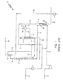
- an existing plant for urea production according to the stripping process with carbon dioxide and featuring the recycle of the reactants to the reaction space is indicated in whole with reference numeral 1.
- Plant 1 and more specifically the high pressure synthesis section, comprises a reactor 2 (or reaction space) for urea synthesis, a stripping unit 3 with carbon dioxide, a condensation section comprising a vertical condensation unit 4 of the film type and a washing unit 5 of the passivating agents and other possible substances inert to the reaction.
- plant 1 comprises a recovery section for the urea produced, not represented in figure 1 , and an apparatus 6 for the separation of the steam produced by the cooling liquid fed to the condensation unit 4.
- the reactor 2 operates usually at a temperature comprised between 180 and 185°C with a molar ratio NH 3 /CO 2 comprised between 2,8 and 3,0, a molar ratio H 2 O/CO 2 comprised between 0,4 and 0,5, and a conversion yield comprised between 58 and 60 %.
- the (isobaric) process pressure in the synthesis section of figure 1 is usually comprised between 140 and 145 bar. Such pressure is usually indicated in the urea synthesis processes as “high” pressure, as compared with the terms “medium” (about 18 bar) and “low” (3-4 bar) pressure, respectively, used in the field to indicate the pressure in the sections downstream the synthesis loop.
- Such feeding means comprises pipelines or connecting ducts, pumps, compressors, ejectors and other devices of known type, generally employed in such kind of plants, and therefore they will not be further described in the following description.
- feeding, connecting or extraction means it is intended to mean pipelines, connecting lines or ducts, pumps, compressor, ejectors or other devices of known type, which are used for transporting a liquid or gaseous flow from a location to another one in the plant.
- the feed carbon dioxide sent to the stripping unit 3 through means 7 is employed as stripping agent of a reaction mixture comprising urea, carbamate and free ammonia in aqueous solution leaving the reactor 2 and fed to the unit 3 through means 9.
- the stripping unit 3 is of the film type with an external heating with steam. Means for feeding and extracting steam for the heating of the stripping unit 3 on the shell side are generally indicated with 22.
- reaction mixture flowing downwards in the unit 3 in countercurrent with the gaseous flow comprising carbon dioxide is subjected to a treatment of partial decomposition of carbamate and partial separation of the free ammonia, obtaining a flow comprising ammonia and carbon dioxide in vapour phase and a flow comprising urea and residual carbamate in aqueous solution.
- the flow comprising urea and residual carbamate in aqueous solution is extracted from the bottom of the stripping unit 3 and sent to the urea recovery section (non represented) through the feeding means 10.
- the condensation unit 4 is of the vertical film type for subjecting to partial condensation all the flow comprising ammonia and carbon dioxide in vapour phase coming from the unit 3 through means 11.
- the flow comprising feed ammonia is fed to the upper end of the condensation unit 4 through means 8 together with a recycled flow comprising ammonia and carbamate in aqueous solution.
- Recycled ammonia and carbamate in aqueous solution are fed into the flow comprising feed ammonia through feeding means 13.
- Connecting means 12 are also provided between the reactor 2 and the feeding means 13.
- the partial condensation of the gaseous phase takes place as a result of the contact of such phase with the liquid phase, flowing in co-current downwards inside a plurality of tubes of a tube bundle enclosed in a shell of the condensation unit 4.
- phase comprising ammonia and carbon dioxide in gaseous phase, as well as the phase comprising carbamate in aqueous solution are hence separately sent from the bottom of the condensation unit 4 to the reactor 2 for urea synthesis through respective feeding means 14, 15.
- the heat produced during the partial condensation of the flow comprising ammonia and carbon dioxide in vapour phase inside the unit 4, is removed by making a cooling liquid, i.e. water, to flow through the tube bundle - on the shell side - producing recovery steam (generally at 4.5 absolute bar).
- a cooling liquid i.e. water
- the water flow is fed on the shell side to the condensation unit 4 through means 16, and extracted from such unit through means 17.
- the water flow coming out of the unit 4, and comprising also the steam produced by indirect heat exchange with the process fluids flowing inside the condensation unit 4 on the tubes side, is fed through means 17 to the apparatus 6 for the separation of the steam produced from the water.
- This water is thus recycled through means 16 to the condensation unit 4 on the shell side, whereas the steam is extracted from the separation apparatus 6 through means 18.
- the separation apparatus 6 is also indicated with the term "steam drum”.
- the plant 1 further comprises the possibility of flowing one or more passivating agents, for example oxygen or air, inert to urea synthesis reaction, through such devices.
- passivating agents for example oxygen or air, inert to urea synthesis reaction
- means are generally provided for feeding a gaseous flow, comprising the passivating agents, to the stripping unit 3 and from such stripping unit to the urea synthesis reactor 2, passing through the condensation unit 4.
- the passivating agents are directly mixed with the gaseous flow comprising feed carbon dioxide, therefore the aforesaid means for feeding the gaseous flow comprising passivating agents corresponds to feeding means 7.
- the gaseous flow comprising carbon dioxide fed to the stripping unit 3 through the means 7 contains a certain amount of other inert substances, for example 1-3 % in volume, which, together with the passivating agents, pass through the various apparatuses of the high pressure synthesis section.
- the flow of inert substances passes through the urea synthesis reactor 2 entraining a part of the unreacted ammonia and carbon dioxide in vapour phase, and is thus fed through means 19 from an upper end of the reactor 2 to the washing unit 5.
- ammonia and carbon dioxide in vapour phase are condensed by means of a washing flow comprising - in the example of figure 1 - carbamate in aqueous solution coming from the urea recovery section (not represented) and fed to the unit 5 through means 20.
- washing unit 5 From the washing unit 5, the extraction of the passivating agents and of the inert substances in general from the high pressure synthesis section takes place through means 21, whereas the washing flow suitably enriched in ammonia and carbon dioxide is sent to the condensation unit 4 through means 13.
- figure 2 With reference to figure 2 , the plant for urea production of figure 1 is advantageously represented suitably modified according to a preferred embodiment of the method of modernisation of the present invention.
- the plant resulting from the method of modernization according to said preferred embodiment of the invention is globally indicated with 46.
- the condensation unit 4 is advantageously modified in its internal so as to permit a substantially total condensation of the gaseous flow comprising ammonia and carbon dioxide coming from the stripping unit 3 in a simple and effective way.
- the existing vertical condensation unit of the film type is advantageously transformed in a vertical condensation unit of the "submerged" type, i.e. with the tube bundle full of condensation liquid, remarkably improving the efficiency of such unit and thus its capacity. Moreover, this change allows to increase the residence time of formation carbamate in the condensation unit 4, which partially reacts in urea.
- Suitable means for transforming a condensation unit of the "film type” in a condensation unit of the "submerged type” is well known in the art.
- Preferred means is that disclosed in EP 1036787 and/or EO 1333918 which are incorporated herein by reference in this regard.
- means 11 of the existing plant of figure 1 are modified and means 36 are provided for feeding the flow comprising ammonia and carbon dioxide in vapour phase from the stripping unit 3 to the bottom of the condensation unit 4.
- Means 36 comprises for example a connection duct.
- the means 8 of the pre-existing plant of figure 1 are modified so as to feed the recycled flow comprising ammonia and carbamate solution in aqueous solution and feed ammonia to the bottom of the condensation unit 8.
- the condensation liquid comprising carbamate in aqueous solution and ammonia is advantageously made to circulate inside the tube bundle with a termosiphon like motion.
- the flow comprising ammonia and carbon dioxide in vapour phase is instead fed through means 36 into the lower space near a lower end of the tube bundle of the condensation unit 4.
- ammonia and carbon dioxide in vapour phase pass through the condensation unit 4 upwards - in co-current with the condensation liquid - gurgling inside the tubes full of liquid of the tube bundle and thus with a considerable exchange coefficient on the tubes side.
- a second stripping unit 47 is provided downstream the synthesis reactor 2.
- means 9 are used for feeding a first portion of the flow of reaction mixture comprising urea, carbamate and free ammonia in aqueous solution leaving the synthesis reactor 2 to the per-existing stripping unit 3, and means 48 are provided for feeding a second portion of the flow of reaction mixture comprising urea, carbamate and free ammonia in aqueous solution leaving the synthesis reactor 2 to the second stripping unit 47.
- the second stripping unit 47 employs a portion of feed carbon dioxide as a stripping agent for the second portion of the reaction mixture comprising urea, carbamate and free ammonia in aqueous solution leaving the reactor 2. Consequently, suitable means 52 are provide for feeding a portion of feed carbon dioxide to the second stripping agent.
- the stripping unit 47 is of the film type with an external heating with steam. Means for feeding and extracting steam for the heating of the stripping unit 47 on the shell side are generally indicated with 51.
- the second stripping unit 47 may employ heat instead of carbon dioxide as stripping agent.
- the heat may be provided by a suitable heating fluid, for example steam, flowing through the tube bundle of the stripping unit 47 on the shell side.
- means 49 are also provided for feeding the second flow comprising ammonia and carbon dioxide in vapour phase leaving the second stripping unit 47 directly to the synthesis reactor 2.
- the reaction temperature inside the synthesis reactor 2 is controlled around optimal values for high conversion yield (thermal balance).
- the method of modernization according to the present embodiment of the invention further provides means 50 for feeding the second flow comprising urea and residual carbamate in aqueous solution leaving the second stripping unit 47 to the urea recovery section (not shown).
- the second flow comprising urea and residual carbamate in aqueous solution leaving the second stripping unit 47 is mixed with the flow comprising urea and residual carbamate in aqueous solution leaving the pre-existing striping unit 3 and the resulting mixture flow is sent to the urea recovery section.
- such a process is characterized in that a first portion of the reaction mixture comprising urea, carbamate and free ammonia coming from the reactor 2 is fed to a stripping section 3 with carbon dioxide where it is subjected to a treatment of partial decomposition of carbamate and partial separation of free ammonia, obtaining a first flow comprising ammonia and carbon dioxide in vapour phase and a first flow comprising urea and residual carbamate in aqueous solution;
- a second portion of said reaction mixture is fed to the second stripping section 47 where it is subjected to a treatment of partial decomposition of carbamate and partial separation of free ammonia, obtaining a second flow comprising ammonia and carbon dioxide in vapour phase and a second flow comprising urea and residual carbamate in aqueous solution
- the first flow and said second flow comprising urea and residual carbamate in aqueous solution leaving the stripping unit 3 and the second stripping unit 47 are sent to an urea recovery section.
- At least a first portion of the second flow comprising ammonia and carbon dioxide in vapour phase leaving the stripping unit 47 is fed directly to the reactor 2 for the thermal balance while at least a portion of the first flow comprising ammonia and carbon dioxide in vapour phase leaving the stripping unit 3 is fed to the condensation unit 4 where it is subjected to a substantially total condensation, obtaining a flow comprising urea and carbamate in liquid phase.
- the flow comprising urea and carbamate in liquid phase obtained in the condensation unit 4 is then recycled to the reactor 2.
- the condensation unit 4 is fed with the entire first flow comprising ammonia and carbon dioxide in vapour phase leaving the stripping section 3 while the reactor 2 is fed with the entire second flow comprising ammonia and carbon dioxide in vapour phase leaving the second stripping section 47.
- reaction mixture comprising urea, carbamate and free ammonia in aqueous solution leaving the reactor 2 is preferably fed in a minor portion to the second stripping unit 47 and in a major portion to the stripping unit 3.
- said minor portion fed to the second stripping unit 47 is about a third (1/3) of the reaction mixture comprising urea, carbamate and free ammonia leaving the reactor 2 and said major portion fed to the stripping unit 3 is about two-thirds of said reaction mixture.
Landscapes
- Chemical & Material Sciences (AREA)
- Organic Chemistry (AREA)
- Organic Low-Molecular-Weight Compounds And Preparation Thereof (AREA)
- Catalysts (AREA)
Abstract
Description
- The present invention relates to a method for the modernisation of a plant for urea production according to the process with stripping with carbon dioxide.
- More specifically, the invention relates to a method for the modernisation of a plant for urea production of the type comprising:
- a reactor for urea synthesis;
- means for feeding ammonia and carbon dioxide to the reactor for urea synthesis;
- a stripping unit with carbon dioxide for subjecting a reaction mixture comprising urea, carbamate and free ammonia in aqueous solution leaving the reactor to a treatment of partial decomposition of carbamate and partial separation of free ammonia, thus obtaining a flow comprising ammonia and carbon dioxide in vapour phase and a flow comprising urea and residual carbamate in aqueous solution, respectively;
- a recovery section for the flow comprising urea and residual carbamate in aqueous solution leaving the stripping unit for separating urea from the residual carbamate in aqueous solution;
- at least one condensation unit of the film type, comprising a tube bundle for subjecting to partial condensation the flow comprising ammonia and carbon dioxide in vapour phase leaving the stripping unit, thus obtaining a liquid flow comprising carbamate in aqueous solution and a gaseous flow comprising ammonia and carbon dioxide in vapour phase;
- means for respectively feeding the flow comprising carbamate in aqueous solution and the flow comprising ammonia and carbon dioxide in vapour phase to the reactor for urea synthesis;
- In the following description and enclosed claims, with the term "modernisation", it is intended to mean the modification of a pre-existing plant with the purpose of improving its performance and obtaining, for example, an increase of the production capacity and/or of the conversion yield and/or a reduction of the energy consumption.
- In the following description and enclosed claims, with the term "condensation unit of the film type", it is intended to mean an apparatus wherein the condensation of the gaseous phase occurs in a liquid film, flowing downwards inside a plurality of tubes in co-current with the gaseous flow. The liquid film flows in contact with the tube wall whereas the gaseous phase flows inside the tubes.
- According to a further aspect, the present invention also relates to a process for urea production as well as to a plant for carrying out such process.
- Methods for the modernisation of existing plants for urea production according to the stripping process with carbon dioxide have been recently set forth in the field.
- In particular,
EP 1036787 discloses a method for the modernization of a plant for urea production as indicated above in which the flow comprising ammonia and carbon dioxide in vapour phase coming from the stripping unit is split in a minor portion and in a major portion. The minor portion is sent directly to the synthesis reactor for controlling the reaction temperature inside it (thermal balance, while the major portion is sent to the condensation unit. - In addition, the pre-existing condensation unit of the film type is modified and in particular it is transformed in a condensation unit of the submerged type for subjecting to substantially total condensation the major portion of the flow comprising ammonia and carbon dioxide in vapour phase leaving the stripping unit, so obtaining a flow comprising urea and carbamate in aqueous solution.
- In this way, higher conversion yield and higher production capacity are obtained thanks to the fact that a condensation unit of the submerged type is used which provides a higher efficiency than that of a condensation unit of the film type.
- In the following description and enclosed claims, with the term "condensation unit of the submerged type", it is intended to mean an apparatus wherein the liquid phase fills (submerges) the tube bundle and wherein the condensation of the gaseous phase occurs by passing through such liquid phase. In other words, in this case, the condensation unit operates having the tube bundle's tubes full of liquid, which is different from the condensation unit of the film type wherein the tubes are substantially empty.
- Although advantageous on several aspects, there is a constant need in this field to provide further methods for modernizing the above-mentioned plant which are able to meet specific needs, while obtaining at the same time high production capacity and/or conversion yield at low investment and operation costs, as well as low energy consumption.
- The technical problem underlying the present invention is therefore that of providing a method for the modernisation of a plant for urea production according to the stripping process with carbon dioxide which allows to obtain high production capacity and conversion yield, implies low energy consumption and investment costs and is technically easy to be implemented.
- According to the present invention, this problem is solved by a method of the aforementioned type, which further comprises the step of:
- providing in said at least one condensation unit means for subjecting to substantially total condensation at least a portion of a flow comprising ammonia and carbon dioxide in vapour phase leaving said stripping unit, obtaining a flow comprising urea and carbamate in aqueous solution,
- providing a second stripping unit,
- providing means for feeding a first portion of the flow of reaction mixture comprising urea, carbamate and free ammonia in aqueous solution leaving the reactor to said stripping unit;
- providing means for feeding a second portion of the flow of reaction mixture comprising urea, carbamate and free ammonia in aqueous solution leaving the reactor to said second stripping unit; and
- providing means for feeding at least a portion of a flow comprising ammonia and carbon dioxide in vapour phase leaving said second stripping unit directly to the synthesis reactor.
- The main advantage of the method of modernization according to the present invention is that of obtaining a substantial de-bottlenecking of the equipment of the high-pressure section downstream the synthesis reactor, which is particularly significant in plants of large installations.
- In this regard, the present invention allows, on the one hand, to remarkably increase the exchange coefficient and therefore the efficiency of the pre-existing condensation unit and, on the other hand, to remarkably improve the efficiency and capacity of processing (stripping) the reaction mixture leaving the synthesis reactor, the latter by simply adding a new stripping unit downstream the reactor.
- This results in a greater overall production capacity and conversion yield than those of prior art plants.
- In addition, the above result is achieved in a simple and effective way, with minimum interventions in the high-pressure synthesis section of the existing plant, and with limited energy consumption.
- Accordingly, the investment, implementation and operation costs required by the method of modernization according to the invention are limited/low as well.
- In this regard, it should be noted that, thanks to the present invention, the pre-existing condensation unit is not upgraded nor replaced with new apparatuses, but advantageously preserved requiring only small internal modifications of the condensation unit(s) in such a way to obtain a substantially total condensation of the gaseous phase fed therein. Furthermore, the addition of a stripping unit downstream the synthesis reactor requires lower investment costs than those required by modifying the existing stripping unit in such a way to increase its capacity.
- Accordingly, the investment, implementation and operation costs required by the method of modernization according to the invention are low as well.
- Furthermore, thanks to the fact of providing means for feeding at least a portion of the flow comprising ammonia and carbon dioxide in vapour phase leaving the new stripping unit directly to the synthesis reactor, the portion of reactants in gaseous phase necessary for controlling the temperature inside the reactor (thermal balance) is not made any longer to pass through the condensation unit together with le liquid phase, as in the prior art. So doing, the condensation unit can be modified internally in such a way to permit the substantial condensation of all the gaseous reactants fed to it (coming from the pre-existing stripping unit and/or the new stripping unit) and hence to operate at the maximum efficiency obtainable.
- According to a preferred embodiment of the invention, the method of modernization further comprises the step of:
- providing means for feeding the entire flow comprising ammonia and carbon dioxide in vapour phase leaving said stripping unit directly to the bottom of said at least one condensation unit;
- providing means for feeding the entire flow comprising ammonia and carbon dioxide in vapour phase leaving said second stripping unit directly to the reactor.
- In this embodiment, no split of a gaseous phase is performed but conversely it is performed only a split of a liquid phase (reaction mixture leaving the reactor) which is advantageously simpler and allows a better control on the portions of liquid phase to be split.
- Furthermore, in this embodiment, the reaction mixture comprising urea, carbamate and free ammonia in aqueous solution is preferably fed in a minor portion to the second (new) stripping unit and in a major portion to the (pre-existing) stripping unit. The amount of minor portion of the reaction mixture to be fed to the second stripping unit depends on the operating conditions of the plant and is chosen in such a way to assures a proper portion of reactants in gaseous phase coming from the second stripping unit to the synthesis reactor for controlling the temperature inside it (thermal balance).
- Preferably, said minor portion fed to the new stripping unit is about a third (1/3) of the reaction mixture comprising urea, carbamate and free ammonia in aqueous solution and said major portion fed to the existing stripping unit is about two-thirds of said reaction mixture.
- According to further aspect of the present invention, the above second stripping unit is of the type using carbon dioxide as a stripping agent and the method of modernization further comprises the step of:
- providing means for sending a portion of feed carbon dioxide to said second stripping unit.
- According to a further aspect, the present invention relates to a process for producing urea characterized in that it comprises the steps of:
- reacting ammonia and carbon dioxide in a reaction space, obtaining a reaction mixture comprising urea, carbamate and free ammonia in aqueous solution;
- feeding a first portion of the reaction mixture to a stripping section with carbon dioxide and subjecting said first portion to a treatment of partial decomposition of carbamate and partial separation of free ammonia, obtaining a first flow comprising ammonia and carbon dioxide in vapour phase and a first flow comprising urea and residual carbamate in aqueous solution;
- feeding a second portion of the reaction mixture to a second stripping section and subjecting said second portion to a treatment of partial decomposition of carbamate and partial separation of free ammonia, obtaining a second flow comprising ammonia and carbon dioxide in vapour phase and a second flow comprising urea and residual carbamate in aqueous solution
- feeding said first flow and said second flow comprising urea and residual carbamate in aqueous solution to an urea recovery section;
- feeding at least a portion of said first flow comprising ammonia and carbon dioxide in vapour phase to at least one condensation unit and subjecting said at least a portion to a substantially total condensation, obtaining a flow comprising urea and carbamate in liquid phase;
- feeding at least a portion of said second flow comprising ammonia and carbon dioxide in vapour phase directly to the reaction space, and
- feeding the flow comprising urea and carbamate in liquid phase to the reaction space.
- According to a further aspect, the present invention further relates to a plant intended for carrying out the aforesaid process for producing urea, comprising:
- a reactor for urea synthesis;
- means for feeding ammonia and carbon dioxide to the reactor for urea synthesis;
- a first stripping unit with carbon dioxide for subjecting a first portion of the reaction mixture comprising urea, carbamate and free ammonia in aqueous solution leaving the reactor to a treatment of partial decomposition of carbamate and partial separation of free ammonia, obtaining a first flow comprising ammonia and carbon dioxide in vapour phase and a first flow comprising urea and residual carbamate in aqueous solution;
- at least one condensation unit of the submerged type;
- a second stripping unit,
- means for feeding a first portion of the flow of reaction mixture comprising urea, carbamate and free ammonia in aqueous solution leaving the reactor to said first stripping unit;
- means for feeding a second portion of the flow of reaction mixture comprising urea, carbamate and free ammonia in aqueous solution leaving the reactor to said second stripping unit, and
- means for feeding at least a portion of a flow comprising ammonia and carbon dioxide in vapour phase leaving said second stripping unit directly to the synthesis reactor.
- According to the invention, the plants intended for carrying out the process for urea production can be realised both ex-novo or by modifying pre-existing plants, so as to obtain an increase in the production capacity and in some cases an improved performance from the point of view of energy consumption.
- Further features and advantages of the present invention will appear more clearly from the following non limiting description of two embodiments of the method of modernisation and of the urea synthesis process according to the invention, made with reference to the attached drawings.
- In such drawings:
-
figure 1 illustrates schematically and partially a plant for urea production according to the stripping process with carbon dioxide of the prior art; -
figure 2 illustrates schematically and partially a plant for urea production according to the stripping process with carbon dioxide realised by the modernisation of the plant offigure 1 in accordance with an embodiment of the method of modernisation according to the invention. - Just to simplify the disclosure of the present invention, only a portion of a plant for urea production is schematically represented in
figure 1 and more precisely the high pressure synthesis section (synthesis loop), the remaining sections being not significant for the comprehension of the present invention. - Further on, specific reference to the per se conventional connecting ducts of the various parts of the plant described hereinbelow and illustrated in
figure 1 , will be made only when strictly necessary. - With reference to
figure 1 , an existing plant for urea production according to the stripping process with carbon dioxide and featuring the recycle of the reactants to the reaction space, is indicated in whole with reference numeral 1. - Plant 1, and more specifically the high pressure synthesis section, comprises a reactor 2 (or reaction space) for urea synthesis, a stripping
unit 3 with carbon dioxide, a condensation section comprising avertical condensation unit 4 of the film type and awashing unit 5 of the passivating agents and other possible substances inert to the reaction. - Moreover, plant 1 comprises a recovery section for the urea produced, not represented in
figure 1 , and anapparatus 6 for the separation of the steam produced by the cooling liquid fed to thecondensation unit 4. - The
reactor 2 operates usually at a temperature comprised between 180 and 185°C with a molar ratio NH3/CO2 comprised between 2,8 and 3,0, a molar ratio H2O/CO2 comprised between 0,4 and 0,5, and a conversion yield comprised between 58 and 60 %. - The (isobaric) process pressure in the synthesis section of
figure 1 is usually comprised between 140 and 145 bar. Such pressure is usually indicated in the urea synthesis processes as "high" pressure, as compared with the terms "medium" (about 18 bar) and "low" (3-4 bar) pressure, respectively, used in the field to indicate the pressure in the sections downstream the synthesis loop. - In
figure 1 , with the numerals 7-21 respective means for feeding the various flows to the apparatuses of plant 1 for urea production are generally indicated. - Such feeding means comprises pipelines or connecting ducts, pumps, compressors, ejectors and other devices of known type, generally employed in such kind of plants, and therefore they will not be further described in the following description.
- Generally, in the present description and in the enclosed claims, and where it is not differently indicated, by the terms: "feeding, connecting or extraction means", it is intended to mean pipelines, connecting lines or ducts, pumps, compressor, ejectors or other devices of known type, which are used for transporting a liquid or gaseous flow from a location to another one in the plant.
- More in particular, with 7 and 8 are indicated respective means for feeding to the stripping unit 3 a gaseous flow comprising feed carbon dioxide, and to the condensation unit 4 a flow comprising feed ammonia (in liquid phase).
- The feed carbon dioxide sent to the stripping
unit 3 throughmeans 7 is employed as stripping agent of a reaction mixture comprising urea, carbamate and free ammonia in aqueous solution leaving thereactor 2 and fed to theunit 3 throughmeans 9. - The stripping
unit 3 is of the film type with an external heating with steam. Means for feeding and extracting steam for the heating of the strippingunit 3 on the shell side are generally indicated with 22. - The reaction mixture flowing downwards in the
unit 3 in countercurrent with the gaseous flow comprising carbon dioxide is subjected to a treatment of partial decomposition of carbamate and partial separation of the free ammonia, obtaining a flow comprising ammonia and carbon dioxide in vapour phase and a flow comprising urea and residual carbamate in aqueous solution. - The flow comprising urea and residual carbamate in aqueous solution is extracted from the bottom of the stripping
unit 3 and sent to the urea recovery section (non represented) through the feeding means 10. - The gaseous flow obtained in the stripping
unit 3 and comprising also water in addition to ammonia and carbon dioxide, flows out from an upper end ofsuch unit 3 and is fed to an upper end of thecondensation unit 4 through feeding means 11. - The
condensation unit 4 is of the vertical film type for subjecting to partial condensation all the flow comprising ammonia and carbon dioxide in vapour phase coming from theunit 3 throughmeans 11. - Further on, the flow comprising feed ammonia is fed to the upper end of the
condensation unit 4 throughmeans 8 together with a recycled flow comprising ammonia and carbamate in aqueous solution. Recycled ammonia and carbamate in aqueous solution are fed into the flow comprising feed ammonia through feeding means 13. Connecting means 12 are also provided between thereactor 2 and the feeding means 13. - The partial condensation of the gaseous phase takes place as a result of the contact of such phase with the liquid phase, flowing in co-current downwards inside a plurality of tubes of a tube bundle enclosed in a shell of the
condensation unit 4. - The phase comprising ammonia and carbon dioxide in gaseous phase, as well as the phase comprising carbamate in aqueous solution are hence separately sent from the bottom of the
condensation unit 4 to thereactor 2 for urea synthesis through respective feeding means 14, 15. - The heat produced during the partial condensation of the flow comprising ammonia and carbon dioxide in vapour phase inside the
unit 4, is removed by making a cooling liquid, i.e. water, to flow through the tube bundle - on the shell side - producing recovery steam (generally at 4.5 absolute bar). - The water flow is fed on the shell side to the
condensation unit 4 throughmeans 16, and extracted from such unit through means 17. - The water flow coming out of the
unit 4, and comprising also the steam produced by indirect heat exchange with the process fluids flowing inside thecondensation unit 4 on the tubes side, is fed throughmeans 17 to theapparatus 6 for the separation of the steam produced from the water. This water is thus recycled throughmeans 16 to thecondensation unit 4 on the shell side, whereas the steam is extracted from theseparation apparatus 6 throughmeans 18. - In the technical language of the field, the
separation apparatus 6 is also indicated with the term "steam drum". - In order to protect the apparatuses of the high pressure synthesis section from corrosion, the plant 1 further comprises the possibility of flowing one or more passivating agents, for example oxygen or air, inert to urea synthesis reaction, through such devices.
- To this end, means are generally provided for feeding a gaseous flow, comprising the passivating agents, to the stripping
unit 3 and from such stripping unit to theurea synthesis reactor 2, passing through thecondensation unit 4. - In the example of
figure 1 , the passivating agents are directly mixed with the gaseous flow comprising feed carbon dioxide, therefore the aforesaid means for feeding the gaseous flow comprising passivating agents corresponds to feeding means 7. - Moreover, the gaseous flow comprising carbon dioxide fed to the stripping
unit 3 through themeans 7 contains a certain amount of other inert substances, for example 1-3 % in volume, which, together with the passivating agents, pass through the various apparatuses of the high pressure synthesis section. - The flow of inert substances passes through the
urea synthesis reactor 2 entraining a part of the unreacted ammonia and carbon dioxide in vapour phase, and is thus fed throughmeans 19 from an upper end of thereactor 2 to thewashing unit 5. - In the
washing unit 5, ammonia and carbon dioxide in vapour phase are condensed by means of a washing flow comprising - in the example offigure 1 - carbamate in aqueous solution coming from the urea recovery section (not represented) and fed to theunit 5 throughmeans 20. - From the
washing unit 5, the extraction of the passivating agents and of the inert substances in general from the high pressure synthesis section takes place throughmeans 21, whereas the washing flow suitably enriched in ammonia and carbon dioxide is sent to thecondensation unit 4 throughmeans 13. - With reference to
figure 2 , the plant for urea production offigure 1 is advantageously represented suitably modified according to a preferred embodiment of the method of modernisation of the present invention. - The plant resulting from the method of modernization according to said preferred embodiment of the invention is globally indicated with 46.
- In
figure 2 , the details ofplant 46 equivalent as for structure and operation to those illustrated infigure 1 will be indicated with the same reference numerals and will not be described again. - Thanks to the present invention, the
condensation unit 4 is advantageously modified in its internal so as to permit a substantially total condensation of the gaseous flow comprising ammonia and carbon dioxide coming from the strippingunit 3 in a simple and effective way. - In other words, the existing vertical condensation unit of the film type is advantageously transformed in a vertical condensation unit of the "submerged" type, i.e. with the tube bundle full of condensation liquid, remarkably improving the efficiency of such unit and thus its capacity. Moreover, this change allows to increase the residence time of formation carbamate in the
condensation unit 4, which partially reacts in urea. - Suitable means for transforming a condensation unit of the "film type" in a condensation unit of the "submerged type" is well known in the art. Preferred means is that disclosed in
EP 1036787 and/orEO 1333918 - In addition, according to the embodiment of
figure 2 , means 11 of the existing plant offigure 1 are modified and means 36 are provided for feeding the flow comprising ammonia and carbon dioxide in vapour phase from the strippingunit 3 to the bottom of thecondensation unit 4.Means 36 comprises for example a connection duct. Furthermore, themeans 8 of the pre-existing plant offigure 1 are modified so as to feed the recycled flow comprising ammonia and carbamate solution in aqueous solution and feed ammonia to the bottom of thecondensation unit 8. - In the
condensation unit 4, the condensation liquid comprising carbamate in aqueous solution and ammonia is advantageously made to circulate inside the tube bundle with a termosiphon like motion. The flow comprising ammonia and carbon dioxide in vapour phase is instead fed throughmeans 36 into the lower space near a lower end of the tube bundle of thecondensation unit 4. - In doing so, ammonia and carbon dioxide in vapour phase pass through the
condensation unit 4 upwards - in co-current with the condensation liquid - gurgling inside the tubes full of liquid of the tube bundle and thus with a considerable exchange coefficient on the tubes side. - Furthermore, according to the present method of modernisation, a second stripping
unit 47 is provided downstream thesynthesis reactor 2. - In addition, means 9 are used for feeding a first portion of the flow of reaction mixture comprising urea, carbamate and free ammonia in aqueous solution leaving the
synthesis reactor 2 to the per-existing strippingunit 3, and means 48 are provided for feeding a second portion of the flow of reaction mixture comprising urea, carbamate and free ammonia in aqueous solution leaving thesynthesis reactor 2 to the second strippingunit 47. - In the present example, the second stripping
unit 47 employs a portion of feed carbon dioxide as a stripping agent for the second portion of the reaction mixture comprising urea, carbamate and free ammonia in aqueous solution leaving thereactor 2. Consequently, suitable means 52 are provide for feeding a portion of feed carbon dioxide to the second stripping agent. - The stripping
unit 47 is of the film type with an external heating with steam. Means for feeding and extracting steam for the heating of the strippingunit 47 on the shell side are generally indicated with 51. - Of course, according to an alternative embodiment (not shown), the second stripping
unit 47 may employ heat instead of carbon dioxide as stripping agent. The heat may be provided by a suitable heating fluid, for example steam, flowing through the tube bundle of the strippingunit 47 on the shell side. - According to the method of modernization of the present invention, means 49 are also provided for feeding the second flow comprising ammonia and carbon dioxide in vapour phase leaving the second stripping
unit 47 directly to thesynthesis reactor 2. In this way, the reaction temperature inside thesynthesis reactor 2 is controlled around optimal values for high conversion yield (thermal balance). - Furthermore, the method of modernization according to the present embodiment of the invention further provides
means 50 for feeding the second flow comprising urea and residual carbamate in aqueous solution leaving the second strippingunit 47 to the urea recovery section (not shown). - In particular, in this embodiment, the second flow comprising urea and residual carbamate in aqueous solution leaving the second stripping
unit 47 is mixed with the flow comprising urea and residual carbamate in aqueous solution leaving thepre-existing striping unit 3 and the resulting mixture flow is sent to the urea recovery section. - The scheme of
figures 2 represents only a preferred embodiment of modernization of existing plants for urea production according to the present invention and nothing prevents new plants to be realised in an advantageous way according to the teachings of the present invention. - In this regard, the advantages described with reference to the modernisation of existing plants recur in the plants realised ex-novo as well, with the exception of the investment costs that are, of course, much higher for a new plant.
- Thanks to the plant of
figure 2 obtained after the modernisation of an existing plant or realized ex-novo, it is advantageously possible to carry out the process for urea production described and claimed in the enclosed claims 5-7. - In particular, such a process is characterized in that a first portion of the reaction mixture comprising urea, carbamate and free ammonia coming from the
reactor 2 is fed to a strippingsection 3 with carbon dioxide where it is subjected to a treatment of partial decomposition of carbamate and partial separation of free ammonia, obtaining a first flow comprising ammonia and carbon dioxide in vapour phase and a first flow comprising urea and residual carbamate in aqueous solution; - In addition, a second portion of said reaction mixture is fed to the second stripping
section 47 where it is subjected to a treatment of partial decomposition of carbamate and partial separation of free ammonia, obtaining a second flow comprising ammonia and carbon dioxide in vapour phase and a second flow comprising urea and residual carbamate in aqueous solution - The first flow and said second flow comprising urea and residual carbamate in aqueous solution leaving the stripping
unit 3 and the second strippingunit 47 are sent to an urea recovery section. - Instead, at least a first portion of the second flow comprising ammonia and carbon dioxide in vapour phase leaving the stripping
unit 47 is fed directly to thereactor 2 for the thermal balance while at least a portion of the first flow comprising ammonia and carbon dioxide in vapour phase leaving the strippingunit 3 is fed to thecondensation unit 4 where it is subjected to a substantially total condensation, obtaining a flow comprising urea and carbamate in liquid phase. The flow comprising urea and carbamate in liquid phase obtained in thecondensation unit 4 is then recycled to thereactor 2. - In particular, according to a preferred embodiment of the process of the invention (
figure 2 ), thecondensation unit 4 is fed with the entire first flow comprising ammonia and carbon dioxide in vapour phase leaving the strippingsection 3 while thereactor 2 is fed with the entire second flow comprising ammonia and carbon dioxide in vapour phase leaving the second strippingsection 47. - In addition, the reaction mixture comprising urea, carbamate and free ammonia in aqueous solution leaving the
reactor 2 is preferably fed in a minor portion to the second strippingunit 47 and in a major portion to the strippingunit 3. - Preferably, said minor portion fed to the second stripping
unit 47 is about a third (1/3) of the reaction mixture comprising urea, carbamate and free ammonia leaving thereactor 2 and said major portion fed to the strippingunit 3 is about two-thirds of said reaction mixture. - The advantages attained with the process according to the present invention are various. In particular it is worth stressing that such process allows to obtain - simply and effectively - high conversion yields and therefore high production capacity, especially in large installation where it is operated a substantial de-bottlenecking of the equipments of the high-pressure loop downstream the synthesis reactor. Further on, its realisation is technically easy, with low energy consumption and investment costs.
- Finally, the scope of protection defined by the method of modernisation according to the present invention shall be considered as being extended - beside the modification of existing structures - also to the particular case of a replacement - because of wear - of the existing condensation unit with a new unit of the submerged type. This specific case occurs whenever the existing unit is at the end of its operating life and does not guarantee a reliable and lasting operation any more.
Claims (12)
- Method for the modernisation of a plant (1) for urea production of the type comprising:- a reactor (2) for urea synthesis;- means (7,8) for feeding ammonia and carbon dioxide to the reactor (2) for urea synthesis;- a stripping unit (3) with carbon dioxide for subjecting a reaction mixture comprising urea, carbamate and free ammonia in aqueous solution leaving the reactor (2) to a treatment of partial decomposition of carbamate and partial separation of free ammonia, thus obtaining a flow comprising ammonia and carbon dioxide in vapour phase and a flow comprising urea and residual carbamate in aqueous solution, respectively;- a recovery section for the flow comprising urea and residual carbamate in aqueous solution leaving the stripping unit (3) for separating urea from the residual carbamate in aqueous solution;- at least one condensation unit (4) of the film type, for subjecting to partial condensation said flow comprising ammonia and carbon dioxide in vapour phase leaving said stripping unit (3), thus obtaining a liquid flow comprising carbamate in aqueous solution and a gaseous flow comprising ammonia and carbon dioxide in vapour phase;- means (14,15) for respectively feeding the flow comprising carbamate in aqueous solution and the gaseous flow comprising ammonia and carbon dioxide in vapour phase to said reactor (2) for urea synthesis,said modernization method further comprising the step of:- providing in said at least one condensation unit (4) means for subjecting to substantially total condensation at least a portion of a flow comprising ammonia and carbon dioxide in vapour phase leaving said stripping unit (3), obtaining a flow comprising urea and carbamate in aqueous solution,and being characterized by comprising the steps of:- providing a second stripping unit (47),- providing means (9) for feeding a first portion of the flow of reaction mixture comprising urea, carbamate and free ammonia in aqueous solution leaving the reactor (2) to said stripping unit (3);- providing means (48) for feeding a second portion of the flow of reaction mixture comprising urea, carbamate and free ammonia in aqueous solution leaving the reactor (2) to said second stripping unit (47); and- providing means (49) for feeding at least a portion of a flow comprising ammonia and carbon dioxide in vapour phase leaving said second stripping unit (47) directly to the synthesis reactor (2).
- Method according to claim 1, characterised in that it further comprises the steps of:- providing means (36) for feeding the entire flow comprising ammonia and carbon dioxide in vapour phase leaving said stripping unit (3) to the bottom of said at least one condensation unit (4).- providing means (49) for feeding the entire flow comprising ammonia and carbon dioxide in vapour phase leaving said second stripping unit (47) directly to the reactor (2).
- Method according to claim 1 or 2, characterised in that it further comprises the step of:- providing means (50) for feeding the flow comprising urea and residual carbamate in aqueous solution leaving said second stripping unit (47) to said urea recovery section.
- Method according to anyone of the preceding claims, characterised in that said second stripping unit (47) is of the type using carbon dioxide as a stripping agent and in that it further comprises the step of:- providing means (52) for sending a portion of feed carbon dioxide to said second stripping unit (47).
- Process for producing urea characterized in that it comprises the steps of:- reacting ammonia and carbon dioxide in a reaction space (2), obtaining a reaction mixture comprising urea, carbamate and free ammonia in aqueous solution;- feeding a first portion of the reaction mixture to a stripping section (3) with carbon dioxide and subjecting said first portion to a treatment of partial decomposition of carbamate and partial separation of free ammonia, obtaining a first flow comprising ammonia and carbon dioxide in vapour phase and a first flow comprising urea and residual carbamate in aqueous solution;- feeding a second portion of the reaction mixture to a second stripping section (47) and subjecting said second portion to a treatment of partial decomposition of carbamate and partial separation of free ammonia, obtaining a second flow comprising ammonia and carbon dioxide in vapour phase and a second flow comprising urea and residual carbamate in aqueous solution- feeding said first flow and said second flow comprising urea and residual carbamate in aqueous solution to an urea recovery section;- feeding at least a portion of said first flow comprising ammonia and carbon dioxide in vapour phase to the at least one condensation unit (4) and subjecting said at least a portion to a substantially total condensation, obtaining a flow comprising urea and carbamate in liquid phase;- feeding at least a portion of said second flow comprising ammonia and carbon dioxide in vapour phase directly to the reaction space (2), and- feeding the flow comprising urea and carbamate in liquid phase to the reaction space (2).
- Process according to claim 5, characterized in that said first flow comprising ammonia and carbon dioxide in vapour phase coming from the stripping unit (3) is fed to the at least one condensation unit (4) and said second flow comprising ammonia and carbon dioxide in vapour phase coming from said second stripping unit (47) is fed to the reaction space (2).
- Process according to claim 5 or 6, characterized in that said second portion of reaction mixture comprising urea, carbamate and free ammonia in aqueous solution fed to the second stripping section (47) is a minor portion of the total flow of reaction mixture leaving the reaction space (2).
- Process according to claim 7, characterized in that said minor portion fed to the second stripping unit (47) is about one third of the total flow of reaction mixture leaving the reaction space (2).
- Plant for urea production, comprising:- a reactor (2) for urea synthesis;- means (7,8) for feeding ammonia and carbon dioxide to the reactor for urea synthesis;- a first stripping unit (3) with carbon dioxide for subjecting a first portion of the reaction mixture comprising urea, carbamate and free ammonia in aqueous solution leaving the reactor (2) to a treatment of partial decomposition of carbamate and partial separation of free ammonia, obtaining a first flow comprising ammonia and carbon dioxide in vapour phase and a first flow comprising urea and residual carbamate in aqueous solution;- at least one condensation unit (4) of the submerged type;characterised in that it further comprises:- a second stripping unit (47),- means (9) for feeding a first portion of the flow of reaction mixture comprising urea, carbamate and free ammonia in aqueous solution leaving the reactor (2) to said first stripping unit (3);- means (48) for feeding a second portion of the flow of reaction mixture comprising urea, carbamate and free ammonia in aqueous solution leaving the reactor (2) to said second stripping unit (47), and- means (49) for feeding at least a portion of a flow comprising ammonia and carbon dioxide in vapour phase leaving said second stripping unit (47) directly to the synthesis reactor (2).
- Plant according to claim 9, characterized in that it comprises:- means (36) for feeding the flow comprising ammonia and carbon dioxide in vapour phase leaving said stripping unit (3) directly to said at least one condensation unit (4) of the submerged type, and- means (49) for feeding the flow comprising ammonia and carbon dioxide in vapour phase leaving said second stripping unit (47) directly to the reactor (2).
- Plant according to anyone of the claim 9 or 10, characterised in that it further comprises:- means (50) for feeding the flow comprising urea and residual carbamate in aqueous solution leaving said second stripping unit (47) to said urea recovery section.
- Plant according to anyone of the claims 9 to 11, characterised in that said second stripping unit (47) is of the type using carbon dioxide as a stripping agent and in that it further comprises:- means (52) for sending a portion of feed carbon dioxide to said second stripping unit (47).
Priority Applications (1)
| Application Number | Priority Date | Filing Date | Title |
|---|---|---|---|
| EP08005391A EP1975152B1 (en) | 2007-03-29 | 2008-03-21 | Method for modernizing a urea production plant |
Applications Claiming Priority (2)
| Application Number | Priority Date | Filing Date | Title |
|---|---|---|---|
| EP07006566A EP1975151A1 (en) | 2007-03-29 | 2007-03-29 | Method for modernizing a urea production plant |
| EP08005391A EP1975152B1 (en) | 2007-03-29 | 2008-03-21 | Method for modernizing a urea production plant |
Publications (2)
| Publication Number | Publication Date |
|---|---|
| EP1975152A1 true EP1975152A1 (en) | 2008-10-01 |
| EP1975152B1 EP1975152B1 (en) | 2010-10-13 |
Family
ID=38473975
Family Applications (2)
| Application Number | Title | Priority Date | Filing Date |
|---|---|---|---|
| EP07006566A Withdrawn EP1975151A1 (en) | 2007-03-29 | 2007-03-29 | Method for modernizing a urea production plant |
| EP08005391A Active EP1975152B1 (en) | 2007-03-29 | 2008-03-21 | Method for modernizing a urea production plant |
Family Applications Before (1)
| Application Number | Title | Priority Date | Filing Date |
|---|---|---|---|
| EP07006566A Withdrawn EP1975151A1 (en) | 2007-03-29 | 2007-03-29 | Method for modernizing a urea production plant |
Country Status (11)
| Country | Link |
|---|---|
| US (1) | US7674933B2 (en) |
| EP (2) | EP1975151A1 (en) |
| CN (1) | CN101274906B (en) |
| AT (1) | ATE484493T1 (en) |
| BR (1) | BRPI0800762B1 (en) |
| CA (1) | CA2627827C (en) |
| DE (1) | DE602008002956D1 (en) |
| EG (1) | EG26014A (en) |
| RU (1) | RU2458915C2 (en) |
| SA (1) | SA08290167B1 (en) |
| UA (1) | UA95610C2 (en) |
Families Citing this family (2)
| Publication number | Priority date | Publication date | Assignee | Title |
|---|---|---|---|---|
| CN105008327B (en) * | 2012-12-28 | 2017-09-12 | 斯塔米卡邦有限公司 | Urea equipment remodeling method |
| IT201700121364A1 (en) * | 2017-10-25 | 2019-04-25 | Saipem Spa | APPARATUS AND METHOD FOR PROCESSING PROCESSED VAPORS FROM A VACUUM CONCENTRATION SECTION OF A UREA PLANT |
Citations (5)
| Publication number | Priority date | Publication date | Assignee | Title |
|---|---|---|---|---|
| EP0136764A2 (en) * | 1983-10-06 | 1985-04-10 | Unie Van Kunstmestfabrieken B.V. | Process for the preparation of urea |
| EP0435008A1 (en) * | 1989-12-29 | 1991-07-03 | Ammonia Casale S.A. | Process and plant for urea production |
| US5660801A (en) * | 1992-11-19 | 1997-08-26 | Urea Casale S.A. | Process and apparatus for the revamping of urea synthesis plants consisting of a stripper with ammonia |
| EP1036787A1 (en) | 1999-03-16 | 2000-09-20 | Urea Casale S.A. | Method for modernizing a urea production plant |
| EP1333918A1 (en) | 2000-10-24 | 2003-08-13 | Urea Casale S.A. | Carbamate condensation unit |
Family Cites Families (1)
| Publication number | Priority date | Publication date | Assignee | Title |
|---|---|---|---|---|
| DE69326881D1 (en) * | 1993-01-07 | 1999-12-02 | Urea Casale Sa | Improved process for producing urea using a carbon dioxide removal step |
-
2007
- 2007-03-29 EP EP07006566A patent/EP1975151A1/en not_active Withdrawn
-
2008
- 2008-03-19 US US12/051,529 patent/US7674933B2/en active Active
- 2008-03-21 EP EP08005391A patent/EP1975152B1/en active Active
- 2008-03-21 AT AT08005391T patent/ATE484493T1/en not_active IP Right Cessation
- 2008-03-21 DE DE602008002956T patent/DE602008002956D1/en active Active
- 2008-03-25 BR BRPI0800762-4A patent/BRPI0800762B1/en active IP Right Grant
- 2008-03-26 SA SA08290167A patent/SA08290167B1/en unknown
- 2008-03-28 RU RU2008111875/04A patent/RU2458915C2/en active
- 2008-03-28 UA UAA200803920A patent/UA95610C2/en unknown
- 2008-03-28 CN CN2008100858695A patent/CN101274906B/en active Active
- 2008-03-28 CA CA2627827A patent/CA2627827C/en active Active
- 2008-03-30 EG EG2008030539A patent/EG26014A/en active
Patent Citations (5)
| Publication number | Priority date | Publication date | Assignee | Title |
|---|---|---|---|---|
| EP0136764A2 (en) * | 1983-10-06 | 1985-04-10 | Unie Van Kunstmestfabrieken B.V. | Process for the preparation of urea |
| EP0435008A1 (en) * | 1989-12-29 | 1991-07-03 | Ammonia Casale S.A. | Process and plant for urea production |
| US5660801A (en) * | 1992-11-19 | 1997-08-26 | Urea Casale S.A. | Process and apparatus for the revamping of urea synthesis plants consisting of a stripper with ammonia |
| EP1036787A1 (en) | 1999-03-16 | 2000-09-20 | Urea Casale S.A. | Method for modernizing a urea production plant |
| EP1333918A1 (en) | 2000-10-24 | 2003-08-13 | Urea Casale S.A. | Carbamate condensation unit |
Also Published As
| Publication number | Publication date |
|---|---|
| CN101274906B (en) | 2013-01-23 |
| US20080242890A1 (en) | 2008-10-02 |
| ATE484493T1 (en) | 2010-10-15 |
| CN101274906A (en) | 2008-10-01 |
| SA08290167B1 (en) | 2012-02-12 |
| US7674933B2 (en) | 2010-03-09 |
| EP1975152B1 (en) | 2010-10-13 |
| EG26014A (en) | 2012-12-10 |
| UA95610C2 (en) | 2011-08-25 |
| RU2008111875A (en) | 2009-10-10 |
| DE602008002956D1 (en) | 2010-11-25 |
| BRPI0800762B1 (en) | 2017-08-01 |
| EP1975151A1 (en) | 2008-10-01 |
| RU2458915C2 (en) | 2012-08-20 |
| CA2627827A1 (en) | 2008-09-29 |
| CA2627827C (en) | 2016-05-10 |
| BRPI0800762A2 (en) | 2008-11-25 |
Similar Documents
| Publication | Publication Date | Title |
|---|---|---|
| EP3436430B1 (en) | Urea production with bi-pressurized synthesis | |
| EP2086928B1 (en) | Process for urea production and related plant | |
| EP2297094B1 (en) | Process for the production of urea from ammonia and carbon dioxide | |
| US6284922B1 (en) | Method for modernizing a urea production plant | |
| JP7094453B2 (en) | Plants with thermal integration in urea production process and low pressure recovery section | |
| US8158823B2 (en) | Method for the modernization of a urea production plant | |
| EP1923383A1 (en) | Method for the modernization of a urea production plant | |
| EP2502881A1 (en) | Process and plant for ammonia-urea production | |
| EP1975152B1 (en) | Method for modernizing a urea production plant | |
| EP2397463A1 (en) | Method for revamping a self-stripping urea plant | |
| EP2123633A1 (en) | Process for the production of urea from ammonia and carbon dioxide | |
| EP1289942B1 (en) | Process and plant for the production of urea | |
| CN115916745B (en) | Thermal stripping urea apparatus and method | |
| EP2358667B1 (en) | Improvement to the high-pressure loop in a process for synthesis of urea | |
| CN1840523B (en) | Process and plant for the production of urea | |
| EP1594820B1 (en) | Process and plant for the production of area | |
| PL188569B1 (en) | Method of and plant for obtaining urea | |
| MXPA06013105A (en) | Process for urea production and related plant. |
Legal Events
| Date | Code | Title | Description |
|---|---|---|---|
| PUAI | Public reference made under article 153(3) epc to a published international application that has entered the european phase |
Free format text: ORIGINAL CODE: 0009012 |
|
| AK | Designated contracting states |
Kind code of ref document: A1 Designated state(s): AT BE BG CH CY CZ DE DK EE ES FI FR GB GR HR HU IE IS IT LI LT LU LV MC MT NL NO PL PT RO SE SI SK TR |
|
| AX | Request for extension of the european patent |
Extension state: AL BA MK RS |
|
| 17P | Request for examination filed |
Effective date: 20090305 |
|
| AKX | Designation fees paid |
Designated state(s): AT BE BG CH CY CZ DE DK EE ES FI FR GB GR HR HU IE IS IT LI LT LU LV MC MT NL NO PL PT RO SE SI SK TR |
|
| 17Q | First examination report despatched |
Effective date: 20090608 |
|
| GRAP | Despatch of communication of intention to grant a patent |
Free format text: ORIGINAL CODE: EPIDOSNIGR1 |
|
| GRAS | Grant fee paid |
Free format text: ORIGINAL CODE: EPIDOSNIGR3 |
|
| GRAA | (expected) grant |
Free format text: ORIGINAL CODE: 0009210 |
|
| AK | Designated contracting states |
Kind code of ref document: B1 Designated state(s): AT BE BG CH CY CZ DE DK EE ES FI FR GB GR HR HU IE IS IT LI LT LU LV MC MT NL NO PL PT RO SE SI SK TR |
|
| REG | Reference to a national code |
Ref country code: GB Ref legal event code: FG4D |
|
| REG | Reference to a national code |
Ref country code: CH Ref legal event code: EP |
|
| REG | Reference to a national code |
Ref country code: IE Ref legal event code: FG4D |
|
| REG | Reference to a national code |
Ref country code: NL Ref legal event code: T3 |
|
| REF | Corresponds to: |
Ref document number: 602008002956 Country of ref document: DE Date of ref document: 20101125 Kind code of ref document: P |
|
| LTIE | Lt: invalidation of european patent or patent extension |
Effective date: 20101013 |
|
| PG25 | Lapsed in a contracting state [announced via postgrant information from national office to epo] |
Ref country code: NO Free format text: LAPSE BECAUSE OF FAILURE TO SUBMIT A TRANSLATION OF THE DESCRIPTION OR TO PAY THE FEE WITHIN THE PRESCRIBED TIME-LIMIT Effective date: 20110113 Ref country code: LT Free format text: LAPSE BECAUSE OF FAILURE TO SUBMIT A TRANSLATION OF THE DESCRIPTION OR TO PAY THE FEE WITHIN THE PRESCRIBED TIME-LIMIT Effective date: 20101013 |
|
| PG25 | Lapsed in a contracting state [announced via postgrant information from national office to epo] |
Ref country code: AT Free format text: LAPSE BECAUSE OF FAILURE TO SUBMIT A TRANSLATION OF THE DESCRIPTION OR TO PAY THE FEE WITHIN THE PRESCRIBED TIME-LIMIT Effective date: 20101013 Ref country code: FI Free format text: LAPSE BECAUSE OF FAILURE TO SUBMIT A TRANSLATION OF THE DESCRIPTION OR TO PAY THE FEE WITHIN THE PRESCRIBED TIME-LIMIT Effective date: 20101013 Ref country code: BG Free format text: LAPSE BECAUSE OF FAILURE TO SUBMIT A TRANSLATION OF THE DESCRIPTION OR TO PAY THE FEE WITHIN THE PRESCRIBED TIME-LIMIT Effective date: 20110113 Ref country code: PT Free format text: LAPSE BECAUSE OF FAILURE TO SUBMIT A TRANSLATION OF THE DESCRIPTION OR TO PAY THE FEE WITHIN THE PRESCRIBED TIME-LIMIT Effective date: 20110214 Ref country code: SI Free format text: LAPSE BECAUSE OF FAILURE TO SUBMIT A TRANSLATION OF THE DESCRIPTION OR TO PAY THE FEE WITHIN THE PRESCRIBED TIME-LIMIT Effective date: 20101013 Ref country code: IS Free format text: LAPSE BECAUSE OF FAILURE TO SUBMIT A TRANSLATION OF THE DESCRIPTION OR TO PAY THE FEE WITHIN THE PRESCRIBED TIME-LIMIT Effective date: 20110213 Ref country code: LV Free format text: LAPSE BECAUSE OF FAILURE TO SUBMIT A TRANSLATION OF THE DESCRIPTION OR TO PAY THE FEE WITHIN THE PRESCRIBED TIME-LIMIT Effective date: 20101013 Ref country code: HR Free format text: LAPSE BECAUSE OF FAILURE TO SUBMIT A TRANSLATION OF THE DESCRIPTION OR TO PAY THE FEE WITHIN THE PRESCRIBED TIME-LIMIT Effective date: 20101013 Ref country code: SE Free format text: LAPSE BECAUSE OF FAILURE TO SUBMIT A TRANSLATION OF THE DESCRIPTION OR TO PAY THE FEE WITHIN THE PRESCRIBED TIME-LIMIT Effective date: 20101013 |
|
| PG25 | Lapsed in a contracting state [announced via postgrant information from national office to epo] |
Ref country code: GR Free format text: LAPSE BECAUSE OF FAILURE TO SUBMIT A TRANSLATION OF THE DESCRIPTION OR TO PAY THE FEE WITHIN THE PRESCRIBED TIME-LIMIT Effective date: 20110114 Ref country code: BE Free format text: LAPSE BECAUSE OF FAILURE TO SUBMIT A TRANSLATION OF THE DESCRIPTION OR TO PAY THE FEE WITHIN THE PRESCRIBED TIME-LIMIT Effective date: 20101013 |
|
| PG25 | Lapsed in a contracting state [announced via postgrant information from national office to epo] |
Ref country code: ES Free format text: LAPSE BECAUSE OF FAILURE TO SUBMIT A TRANSLATION OF THE DESCRIPTION OR TO PAY THE FEE WITHIN THE PRESCRIBED TIME-LIMIT Effective date: 20110124 Ref country code: CZ Free format text: LAPSE BECAUSE OF FAILURE TO SUBMIT A TRANSLATION OF THE DESCRIPTION OR TO PAY THE FEE WITHIN THE PRESCRIBED TIME-LIMIT Effective date: 20101013 Ref country code: EE Free format text: LAPSE BECAUSE OF FAILURE TO SUBMIT A TRANSLATION OF THE DESCRIPTION OR TO PAY THE FEE WITHIN THE PRESCRIBED TIME-LIMIT Effective date: 20101013 |
|
| PLBE | No opposition filed within time limit |
Free format text: ORIGINAL CODE: 0009261 |
|
| STAA | Information on the status of an ep patent application or granted ep patent |
Free format text: STATUS: NO OPPOSITION FILED WITHIN TIME LIMIT |
|
| PG25 | Lapsed in a contracting state [announced via postgrant information from national office to epo] |
Ref country code: PL Free format text: LAPSE BECAUSE OF FAILURE TO SUBMIT A TRANSLATION OF THE DESCRIPTION OR TO PAY THE FEE WITHIN THE PRESCRIBED TIME-LIMIT Effective date: 20101013 Ref country code: DK Free format text: LAPSE BECAUSE OF FAILURE TO SUBMIT A TRANSLATION OF THE DESCRIPTION OR TO PAY THE FEE WITHIN THE PRESCRIBED TIME-LIMIT Effective date: 20101013 Ref country code: SK Free format text: LAPSE BECAUSE OF FAILURE TO SUBMIT A TRANSLATION OF THE DESCRIPTION OR TO PAY THE FEE WITHIN THE PRESCRIBED TIME-LIMIT Effective date: 20101013 Ref country code: RO Free format text: LAPSE BECAUSE OF FAILURE TO SUBMIT A TRANSLATION OF THE DESCRIPTION OR TO PAY THE FEE WITHIN THE PRESCRIBED TIME-LIMIT Effective date: 20101013 |
|
| 26N | No opposition filed |
Effective date: 20110714 |
|
| PG25 | Lapsed in a contracting state [announced via postgrant information from national office to epo] |
Ref country code: MC Free format text: LAPSE BECAUSE OF NON-PAYMENT OF DUE FEES Effective date: 20110331 |
|
| REG | Reference to a national code |
Ref country code: DE Ref legal event code: R097 Ref document number: 602008002956 Country of ref document: DE Effective date: 20110714 |
|
| PG25 | Lapsed in a contracting state [announced via postgrant information from national office to epo] |
Ref country code: IT Free format text: LAPSE BECAUSE OF FAILURE TO SUBMIT A TRANSLATION OF THE DESCRIPTION OR TO PAY THE FEE WITHIN THE PRESCRIBED TIME-LIMIT Effective date: 20101013 Ref country code: MT Free format text: LAPSE BECAUSE OF FAILURE TO SUBMIT A TRANSLATION OF THE DESCRIPTION OR TO PAY THE FEE WITHIN THE PRESCRIBED TIME-LIMIT Effective date: 20101013 |
|
| REG | Reference to a national code |
Ref country code: IE Ref legal event code: MM4A |
|
| PG25 | Lapsed in a contracting state [announced via postgrant information from national office to epo] |
Ref country code: DE Free format text: LAPSE BECAUSE OF NON-PAYMENT OF DUE FEES Effective date: 20111001 Ref country code: IE Free format text: LAPSE BECAUSE OF NON-PAYMENT OF DUE FEES Effective date: 20110321 |
|
| REG | Reference to a national code |
Ref country code: DE Ref legal event code: R119 Ref document number: 602008002956 Country of ref document: DE Effective date: 20111001 |
|
| REG | Reference to a national code |
Ref country code: CH Ref legal event code: PL |
|
| GBPC | Gb: european patent ceased through non-payment of renewal fee |
Effective date: 20120321 |
|
| PG25 | Lapsed in a contracting state [announced via postgrant information from national office to epo] |
Ref country code: CH Free format text: LAPSE BECAUSE OF NON-PAYMENT OF DUE FEES Effective date: 20120331 Ref country code: LI Free format text: LAPSE BECAUSE OF NON-PAYMENT OF DUE FEES Effective date: 20120331 Ref country code: GB Free format text: LAPSE BECAUSE OF NON-PAYMENT OF DUE FEES Effective date: 20120321 |
|
| PG25 | Lapsed in a contracting state [announced via postgrant information from national office to epo] |
Ref country code: LU Free format text: LAPSE BECAUSE OF NON-PAYMENT OF DUE FEES Effective date: 20110321 Ref country code: CY Free format text: LAPSE BECAUSE OF FAILURE TO SUBMIT A TRANSLATION OF THE DESCRIPTION OR TO PAY THE FEE WITHIN THE PRESCRIBED TIME-LIMIT Effective date: 20101013 |
|
| PG25 | Lapsed in a contracting state [announced via postgrant information from national office to epo] |
Ref country code: TR Free format text: LAPSE BECAUSE OF FAILURE TO SUBMIT A TRANSLATION OF THE DESCRIPTION OR TO PAY THE FEE WITHIN THE PRESCRIBED TIME-LIMIT Effective date: 20101013 |
|
| PG25 | Lapsed in a contracting state [announced via postgrant information from national office to epo] |
Ref country code: HU Free format text: LAPSE BECAUSE OF FAILURE TO SUBMIT A TRANSLATION OF THE DESCRIPTION OR TO PAY THE FEE WITHIN THE PRESCRIBED TIME-LIMIT Effective date: 20101013 |
|
| REG | Reference to a national code |
Ref country code: FR Ref legal event code: PLFP Year of fee payment: 9 |
|
| REG | Reference to a national code |
Ref country code: FR Ref legal event code: PLFP Year of fee payment: 10 |
|
| REG | Reference to a national code |
Ref country code: FR Ref legal event code: PLFP Year of fee payment: 11 |
|
| PGFP | Annual fee paid to national office [announced via postgrant information from national office to epo] |
Ref country code: FR Payment date: 20230222 Year of fee payment: 16 |
|
| P01 | Opt-out of the competence of the unified patent court (upc) registered |
Effective date: 20230527 |
|
| PGFP | Annual fee paid to national office [announced via postgrant information from national office to epo] |
Ref country code: NL Payment date: 20240220 Year of fee payment: 17 |