EP1973085B1 - Verfahren zum Erkennen eines Feuerumstands in einem überwachten Bereich - Google Patents
Verfahren zum Erkennen eines Feuerumstands in einem überwachten Bereich Download PDFInfo
- Publication number
- EP1973085B1 EP1973085B1 EP08153200A EP08153200A EP1973085B1 EP 1973085 B1 EP1973085 B1 EP 1973085B1 EP 08153200 A EP08153200 A EP 08153200A EP 08153200 A EP08153200 A EP 08153200A EP 1973085 B1 EP1973085 B1 EP 1973085B1
- Authority
- EP
- European Patent Office
- Prior art keywords
- band
- fire
- waveband
- measurement values
- sensor
- Prior art date
- Legal status (The legal status is an assumption and is not a legal conclusion. Google has not performed a legal analysis and makes no representation as to the accuracy of the status listed.)
- Ceased
Links
Images

Classifications
-
- G—PHYSICS
- G08—SIGNALLING
- G08B—SIGNALLING SYSTEMS, e.g. PERSONAL CALLING SYSTEMS; ORDER TELEGRAPHS; ALARM SYSTEMS
- G08B17/00—Fire alarms; Alarms responsive to explosion
- G08B17/12—Actuation by presence of radiation or particles, e.g. of infrared radiation or of ions
-
- G—PHYSICS
- G01—MEASURING; TESTING
- G01N—INVESTIGATING OR ANALYSING MATERIALS BY DETERMINING THEIR CHEMICAL OR PHYSICAL PROPERTIES
- G01N21/00—Investigating or analysing materials by the use of optical means, i.e. using sub-millimetre waves, infrared, visible or ultraviolet light
- G01N21/17—Systems in which incident light is modified in accordance with the properties of the material investigated
- G01N21/25—Colour; Spectral properties, i.e. comparison of effect of material on the light at two or more different wavelengths or wavelength bands
- G01N21/31—Investigating relative effect of material at wavelengths characteristic of specific elements or molecules, e.g. atomic absorption spectrometry
- G01N21/35—Investigating relative effect of material at wavelengths characteristic of specific elements or molecules, e.g. atomic absorption spectrometry using infrared light
- G01N21/3504—Investigating relative effect of material at wavelengths characteristic of specific elements or molecules, e.g. atomic absorption spectrometry using infrared light for analysing gases, e.g. multi-gas analysis
Definitions
- the present invention relates to a method for detecting a fire condition in a monitored region, and in particular, it concerns a method for detecting organic and inorganic fuel fires at relatively long ranges and/or for detecting relatively small organic and inorganic fires.
- Existing optical flame detectors are limited in their detection range and in their spectral response to either organic fuel flames (such as flames having a CO 2 spectral peak) or inorganic fuel flames (such as flames having a H 2 O spectral peak).
- organic fuel flames such as flames having a CO 2 spectral peak
- inorganic fuel flames such as flames having a H 2 O spectral peak.
- the detection range can be increased by increasing system sensitivity, e.g. by appropriately setting an amplification level and/or a threshold level.
- an increase in sensitivity also tends to increase the false alarm rate, which is caused by spurious radiation sources such as: sunlight; artificial light; welding; electrical heaters; ovens; etc., or by other sources of radiation "noise”.
- spurious radiation sources might not be intense enough to activate short-range detectors, but they may be sufficient to activate a detector whose sensitivity has been increased for an increased detection range.
- a false alarm can result in a costly discharge of a fire extinguisher. Furthermore, if the fire extinguisher is of the type requiring replacement before it can be reused, the false alarm can serve to effectively disable the fire extinguisher system until the extinguisher system has been replaced.
- European patent EP0926647B1 and US patent 5,373,159 describe a triple-IR method for detecting fire condition using three sensors, each sensitive to a different wavelength bands.
- the first band is sensitive to wavelengths, which include the CO 2 emission band, and the second and third bands are sensitive to wavelengths shorter and longer than the CO 2 band.
- This method is reliable in distinguishing between the radiation emitted by flames having hot CO 2 content (e.g. hydrocarbon fires) and other environmental and spurious radiation sources.
- the method allows increased sensitivity and speed of detection while keeping the probability of false alarms low.
- the method only allows detection of flames from organic materials (hydrocarbons) which emit CO 2 in the combustion process.
- Flames from fuels such as Hydrogen, Hydrazine, Hydroxyl fuels and Ammonia do not emit any CO 2 in the combustion process, but they do emit large amounts of hot water vapors. Flames from these sources can be detected using a similar triple-IR method, where the first sensor is sensitive to wavelengths in one of the water IR emission bands (for example at wavelengths around 2.7 microns). The second and third sensors are sensitive to wavelengths shorter and longer than the water emission band. Such a method can enable detection of water vapor emitting flames with great sensitivity and with a low probability of false alarm. However, this method does not allow detection of flames that do not produce enough water vapor to emit a significant spectral peak in the water emission band.
- the two methods described above namely for detection of CO 2 -emitting flames and water vapor-emitting flames, do not distinguish efficiently between flames that should be detected and other sources of hot CO 2 and/or water vapor, such as steam pipes, industrial burners, and ovens.
- the characteristic which differentiates between flames and such hot gas sources is the hot gas (i.e. fire combustion product) temperature.
- the temperature of the gas in the combustion process inside the flame is typically much higher than that of a gas emitted from spurious sources such as steam pipes and ovens.
- the temperature difference between these different sources has implications on source emission spectral characteristics. For higher temperatures, the gas emits radiation with an intensity more concentrated in shorter wavelengths. For lower temperatures, the radiation intensity is more concentrated in longer wavelengths.
- the monitored wavelength bands of the three sensors in the methods described hereinabove are not spread far enough across the spectrum to effectively discriminate between flames and spurious hot sources. If these bands are moved further apart from each other, it would be possible to differentiate between flame temperatures and hot vapor/CO 2 temperatures; but the reliability of detection of the CO 2 or water vapor spectral peaks would be severely compromised.
- Some methods exist e.g. US patents 5,612,676 and 5,311,167 , for detection of both hydrocarbon flames (such as CO 2 emitting flames) and some non-hydrocarbon flames (e.g. Hydrogen or Ammonia).
- these methods are either less sensitive to the detection of a fire or more prone to false alarms than the triple-IR methods noted hereinabove.
- the tendency to be less sensitive and/or more prone to false alarms is due to the fact that in these methods not enough data is gathered from the sensors to confidently distinguish between flames (having intensity peak at the CO 2 or water vapor emission wavebands) and other sources that do not have these spectral peaks.
- a system for detecting hydrocarbon and hydrogen fires provided with four detectors is known from US 4,220,857 .
- the present invention is a method for detecting a fire condition in a monitored region, as set forth in claim 1.
- it concerns a method for detecting organic and inorganic fuel fires at relatively long ranges and/or for detecting relatively small organic and inorganic fires.
- a method of detecting a fire condition in a monitored region including the operations of: concurrently monitoring the region using: a plurality of fire combustion product emission band sensors, each band sensor sensitive to radiation within a respective waveband which includes at least part of a respective fire combustion product emission band of a plurality of fire combustion products, the plurality of fire combustion products equal to n; a first reference band sensor sensitive to radiation within a first reference waveband which includes at least some wavelengths shorter than the n fire combustion product emission bands; and a second reference band sensor sensitive to radiation within a second reference waveband which includes at least some wavelengths longer than the n fire combustion product emission bands; and using the band sensors to obtain n + 2 measurement values of radiation intensity emitted from the monitored region in determining the presence or absence of the fire condition.
- the n + 2 measurement values include: n measurement values obtained from the emission band sensors; one measurement value obtained from the first reference band sensor; and one measurement value obtained from the second reference band sensor and from which detection parameters are calculated, which are evaluated against at least one threshold in determining the presence or absence of the fire condition.
- the detection parameters include two respective reference ratios calculated for each of the n measurement values: a first reference ratio between respective n measurement values and the measurement value from the first reference band sensor; and a second reference ratio between respective n measurement values and the measurement value from the second reference band sensor.
- the detection parameters further include ratios calculated for each of the n measurement values, between a respective measurement value and other measurement values.
- the detection parameters further include a first-to-second reference ratio calculated between respective measurement values from the first and second reference band sensors.
- the detection parameters include two respective correlation values calculated for each of the n measurement values, a first reference correlation between respective n measurement values and the measurement value from the first reference band sensor, and a second reference correlation between respective n measurement values and the measurement value from the second reference band sensor.
- individual fire combustion products are identified.
- the at least one threshold includes a threshold value associated with respective measurement values and with respective correlation values.
- the at least one threshold value is determined by at least one chosen from a list including: empirical means and non-empirical means.
- n 2 and the plurality of fire combustion products is chosen from a list including: CO 2 and H 2 O, and CO 2 and OH, and SO 2 and H 2 O, and SO 2 and OH, and NO 2 and H 2 O, and NO 2 and OH.
- n 3 and the plurality of fire combustion products is: CO 2 and H 2 O and SO 2 , or NO 2 and H 2 O and SO 2 .
- respective band sensors are sensitive to infrared radiation and or to ultraviolet radiation.
- the plurality of fire combustion product emission band sensors includes a first band sensor [IR 1 ], having a sensitivity to a waveband which includes part of the 4.2 to 4.7 ⁇ m CO 2 emission band, and a second band sensor [IR 2 ], having a sensitivity to a waveband which includes at least part of the 2.4 to 3.1 ⁇ m H 2 O emission band; the first reference sensor [IR 3 ], having a sensitivity to waveband, which includes at least some wavelengths shorter than the wavebands of sensors [IR 1 ] and [IR 2 ]; and the second reference sensor [IR 4 ], having a sensitivity to waveband, which includes at least some wavelengths longer than the wavebands of sensors [IR1] and [IR2].
- IR 1 a sensitivity to a waveband which includes part of the 4.2 to 4.7 ⁇ m CO 2 emission band
- a second band sensor [IR 2 ] having a sensitivity to a waveband which includes at least part of the 2.4 to 3.1 ⁇ m H 2 O emission band
- a method of detecting a fire condition in a monitored region including the operations of: concurrently monitoring the region using: a plurality of fire combustion product emission band sensors, each band sensor sensitive to radiation within a respective waveband which includes at least part of a respective fire combustion product emission band of a plurality of fire combustion products, the plurality of fire combustion products equal to n; a first reference band sensor sensitive to radiation within a first reference waveband which includes only wavelengths shorter than the n fire combustion product emission bands; and a second reference band sensor sensitive to radiation within a second reference waveband which includes only wavelengths longer than the n fire combustion product emission bands; and using the band sensors to obtain n + 2 measurement values of radiation intensity emitted from the monitored region in determining the presence or absence of the fire condition.
- the n + 2 measurement values include: n measurement values obtained from the emission band sensors; one measurement value obtained from the first reference band sensor; and one measurement value obtained from the second reference band sensor and from which detection parameters are calculated, which are evaluated against at least one threshold in determining the presence or absence of the fire condition.
- the present invention is a method for detecting a fire condition in a monitored region, and in particular, it concerns a method for detecting organic and inorganic fuel fires at relatively long ranges and/or for detecting relatively small organic and inorganic fires.
- One of the embodiments of the present invention allows highly sensitive and reliable detection of both hydrocarbon flames and non-hydrocarbon flames that emit large amounts of water vapor in their combustion process, with extremely low probability of false alarms, even from other sources of hot CO 2 or water vapor, and at a relatively low cost.
- the low cost afforded by an embodiment of the present invention is obtained by being able to use a single detector unit with four sensors for detection of fires of types and from distances that would alternatively require the use of at least two detectors, and a larger total number of sensors.
- additional sensors preferably with the use of a single detector, allows scaling of configurations of embodiments of the present invention to allow economical and reliable detection of more complicated fire types and/or of additional gases from fire combustion products.
- Fire combustion product is used to mean a product, usually of a gaseous form, originating from a fire which may be detected by embodiments of the present invention.
- gas is used interchangeably hereinbelow in reference to a fire combustion product.
- Imaging value is intended to mean a value that is calculated from output of a sensor sensing radiation intensity.
- An intensity value may be derived from a single instantaneous measurement or it may be a series of measurements over a time interval.
- the calculated value may be the result of any one or a combination of: electronic filtering and amplification, digital filtering, and one or more mathematical operations and/or transformations.
- Sensor configuration is used to include additional components frequently closely associated with sensors, as known in the art, such as but not limited to filters and/or other electro optic components.
- sensors such as but not limited to filters and/or other electro optic components.
- sensor configuration and “sensor” are intended to have the same meaning.
- Detection parameters is intended to mean parameters expressed as ratios between respective intensity values and/or parameters expressed as correlations between respective intensity values.
- Ratio or ratio value is intended to mean a value reflecting a measure of the relation between two measurement values.
- a ratio may be expressed simply as a division of one measurement value by another or by any other function or transformation between the two measurement values.
- Correlation or correlation value is intended to mean a value that relates to the similarity of the temporal behavior of two measurement values being compared.
- a correlation may be expressed as any known statistical function or other function or transformation between the two measurement values.
- Theshold is intended to mean a value that is determined by empirical or by non-empirical means by which one or more detection parameters are evaluated, so as to determine a fire condition or not.
- Waveband is used interchangeably with “wavelength band”, both expressions intended to mean a characteristic range of wavelengths
- emission band of a particular fire combustion product is intended to mean a waveband comprising only those wavelengths which a particular fire combustion product emits and which are incident on a fire detector with significant intensity.
- significant intensity, and therefore wavelengths included in the emission band itself may vary according to the considered application, such as but not limited to: fire type, fire distance from the detector, expected atmospheric conditions, and expected background radiation.
- “Includes”, when used in reference to a waveband, is intended to mean the inclusion of a waveband in its entirety or partially, and the inclusion of the waveband with or without the inclusion of additional wavebands.
- “A waveband, which includes the CO 2 emission band” is intended to mean any waveband, which includes the entire CO 2 emission band, or which includes only parts of the CO 2 emission band.
- the waveband may include other wavelengths outside the CO 2 emission band as long as the waveband also includes at least a part of the CO 2 emission band.
- the waveband may not solely include wavelengths outside the CO 2 emission band.
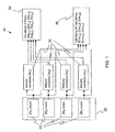
- FIG. 1 is a block diagram illustrating output from sensor configurations 20 and calculation of detection parameters 30, in accordance with an embodiment of the current invention.
- the sensors and wavelengths noted immediately hereinbelow refer to an embodiment of the present invention taking advantage of infrared (IR) radiation, although other radiation having other wavelengths, such as but not limited to ultraviolet radiation may be employed.
- IR infrared
- sensor configurations 20 are part of a single detector 22, thereby reducing the sensor configuration cost.
- the four sensor configurations indicated as [IR 1 ], [IR 2 ], [IR 3 ], and [IR 4 ] have the following functions.
- the sensor configuration which may include a filter (not shown), that is sensitive to radiation variations within a wavelength band that includes at least part of one of the CO 2 emission bands.
- the sensor configuration which may include a filter (not shown), that is sensitive to radiation variations within a wavelength band that includes at least part of one of the water vapor emission bands.
- the sensor configuration which may include a filter (not shown), that is sensitive to radiation variations within a wavelength band, which includes wavelengths shorter than both those of the CO 2 emission bands and the water vapor emission bands.
- the selected wavelength band may include wavelengths within the CO 2 wavebands; however the portion of measured intensity, corresponding to the CO 2 bands, compared to the total measured intensity, must be lower than the portion of the measured intensity corresponding to the CO 2 wavebands of the [IR 1 ] waveband.
- the selected wavelength band may include wavelengths within the water vapor wavebands; however the portion of measured intensity, corresponding to the water vapor wavebands, compared to the total measured intensity, must be lower than the portion of the measured intensity, corresponding to the water wavebands, of the [IR 2 ] waveband.
- the selected wavelength band may include only wavelengths shorter than both those of the CO 2 emission bands and the water vapor emission bands.
- the sensor configuration which may include a filter (not shown), that is sensitive to radiation variations within a wavelength band, which includes wavelengths, longer than both the CO 2 and water vapor emission bands.
- the selected wavelength band may include wavelengths within the CO 2 wavebands; however the portion of measured intensity, corresponding to the CO 2 bands, compared to the total measured intensity, must be lower than the portion of the measured intensity corresponding to the CO 2 bands, of the [IR 1 ] waveband.
- the selected wavelength band may include wavelengths within the water vapor wavebands; however the portion of measured intensity, corresponding to the water vapor wavebands, compared to the total measured intensity, must be lower than the portion of the measured intensity, corresponding to the water wavebands, of the [IR 2 ] waveband.
- the selected wavelength band may include only wavelengths longer than both those of the CO 2 emission bands and the water vapor emission bands,
- Output from respective sensor configurations [IR 1 ], [IR 2 ], [IR 3 ] and [IR 4 ] is then passed to respective intensity calculation modules 32, to form respective measurement values of the emitted radiation.
- Output from respective sensor configurations is typically filtered and amplified and then transformed into digital format and further filtered by software when transferred to the intensity calculation modules.
- For each of the transformed outputs a respective measurement value ([Int 1 ], [Int 2 ], [Int 3 ] and [Int 4 ]) is calculated.
- the calculation may be performed in several ways, for example: using the absolute value of the output, or using the square of the output value.
- the measurement value may be calculated according to an instantaneous value of the output, or the measurement value may be calculated by integrating the output over a certain period, with or without weighting.
- Other calculation methods such as the use of the Fourier transform (FT) or wavelet calculations may also be employed to obtain several measurement values for each sensor configuration, thereby providing an analysis of the intensity in several bands of frequencies, or of other similar merits.
- FT Fourier transform
- wavelet calculations may also be employed to obtain several measurement values for each sensor configuration, thereby providing an analysis of the intensity in several bands of frequencies, or of other similar merits.
- Another example of an intensity calculation module calculation is the use of an autocorrelation function between the output and itself.
- Rat i ,j Int i - Int j / Int j ;
- Rat i , j Int i / Int j + Int j ;
- Rat i , j log Int i / Int j :
- Rat i , j Int i 2 / Int j 2 + Int j 2 .
- a ratio is calculated for each pair of measurement values, corresponding to each pair of sensor configurations. [Rat i,j ] is therefore expressed as: [Rat 2,1 ], [Rat 1,3 ], [Rat 1,4 ], [Rat 2,3 ], [Rat 2,4 ] and [Rat 3,4 ].
- Correlation values [Corr i,j ] are calculated in correlation calculation modules 36, between pairs of respective measurement values, such as between measurement value i and measurement value j.
- [Corr i,j ] can be calculated in any way that results in a value that relates to the similarity of the temporal behavior of the two signals. For example, the value of a mathematical correlation function between the two signals as functions of time can be obtained. [Corr i,j ] can then be defined and calculated as the value of the correlation function at 0, or as a weighted average of the correlation function over a range of values.
- Another example of a calculation for the correlation value [Corr i,j ] is by evaluating a certain time period and changing the sign (i.e. "+” or "-") of the measurement value i according to measurement value j.
- the sign of measurement value i is reversed, and when measurement value j has a positive value, the sign of measurement value i is retained.
- the measurement value with the reversed sign (i) is then integrated over the time period to obtain a value for the correlation.
- the correlation can also be calculated in a normalized fashion, i.e. so that the value is assured to be in a certain range, for example 0 to 1. It can also be calculated without normalization.
- correlation values are calculated as: [Corr 1,2 ], [Corr 1,3 ], [Corr 1,4 ], [Corr 2,3 ] and [Corr 2,4 ].
- CO 2 emission bands and H 2 O emission bands are sensed and respective measurement values are analyzed.
- appropriate emission bands for sensor configurations [IR 1 ], [IR 2 ], [IR 3 ] and [IR 4 ] could be 4.3 to 4.6 ⁇ m, 2.5 to 2.9 ⁇ m, 2.0 to 2.6 ⁇ m, and 4.5 to 5.0 ⁇ m, respectively.
- the [IR 1 ] waveband includes at least part of the 4.2 to 4.7 ⁇ m CO 2 band
- the [IR 2 ] waveband includes at least part of the 2.4 to 3.1 ⁇ m water vapor band
- the [IR 3 ] waveband includes at least some wavelengths lower than wavebands of both [IR 1 ] and [IR 2 ]
- the [IR 4 ] waveband includes at least some wavelengths higher than wavebands of both [IR 1 ] and [IR 2 ].
- the wavelength bands of [IR 3] and [IR 4] may include wavelengths within the 4.2 to 4.7 ⁇ m CO 2 band, as long as the portion of measured intensity, which results from 4.2 to 4.7 ⁇ m band, compared to the total measured intensity, is lower than the similar portion of the waveband of [IR 1 ].
- the wavelength bands of [IR 3] and [IR 4] may include wavelengths within the 2.4 to 3.1 ⁇ m water vapor band, as long as the portion of measured intensity, which results from the 2.4 to 3.1 ⁇ m band, compared to the total measured intensity, is lower than the similar portion of the waveband of [IR 2 ].
- the [IR 3 ] waveband includes only wavelengths lower than wavebands of both [IR 1 ] and [IR 2 ], and the [IR 3 ] waveband includes only wavelengths shorter than wavebands of both [IR 1 ] and [IR 2 ].
- fire combustion products or other combinations of fire combustion products such as but not limited to: CO 2 and H 2 O, CO 2 and SO 2 , NO 2 and CO 2 , SO 2 and H 2 O, NO 2 and H 2 O, NO 2 and SO 2 , and OH and CO 2 can be used in other embodiments of the present invention, with appropriate emission bands for sensor configurations [IR 1 ], [IR 2 ], [IR 3 ] and [IR 4 ], mutatis mutandis.
- FIG 2 is a flow chart indicating steps to determine a fire condition, using the detection parameters shown in FIG. 1 and in accordance with an embodiment of the current invention.
- the measurement values and detection parameters are obtained as described hereinabove, they are used to determine whether there is a fire condition or not -otherwise referred to in the specification claims which follow as "to detect a fire” or "to detect a fire condition”.
- the determination or decision as to whether there is a fire condition or not is based on a comparison of some or all of the detection parameters according to a predetermined threshold value (not shown in the current figure).
- the threshold value is typically determined in an empirical process for a given detection parameter, as described further hereinbelow. Alternatively or optionally, the threshold value may be determined in a non-empirical manner.
- not all detection parameters need to be evaluated against respective threshold values or not all detection parameters need to pass respective threshold values for a determination to be made that there is a fire condition.
- One such heuristic path 48 is shown in FIG 2 .
- a fire condition is declared if there is at least one path from the Start 50 to Fire Condition 52, in which all the variables/evaluations, passed on the way, fulfill their respective thresholds.
- Heuristic path 48 is typically performed repetitively and/or iteratively as frequently as many times per second, with step 56 [Int 2 ], [Rat 2,3 ], [Rat 2,4 ] and step 68 [Int 1 ], [Rat 1,3 ], [Rat 1,4 ] and subsequent steps being calculated each time to make a determination of (or "to declare") a fire condition.
- step 56 [Int 2 ], [Rat 2,3 ], [Rat 2,4 ], step 60 [Corr 1,2 ], and step 64, [Rat 2,1 ] [Rat 3,4 ] all fulfill their threshold conditions (meaning respective steps yields a "yes” condition)
- fire condition 52 is declared regardless of the results ("yes” or "no") of other steps, namely steps 74, 68 and 72.
- fire condition 52 is declared, if step 68, [Int 1 ], [Rat 1,3 ], [Rat 1,4 ], step 72 [Corr 1,3 ], [Corr 1,4 ] and step 64, [Rat 2,1 ] [Rat 3,4 ], all fulfill their threshold conditions (meaning respective steps yields a "yes” condition), regardless of the results ("yes” or "no") of the other steps, namely 56, 60 and 74).
- step 56 and 68 indicate that the respective following steps, i.e. 74, 60, and 72 are evaluated without regard to the results of steps 56 and 68.
- the two vertical dotted lines shown in FIG. 2 identify three regions in the figure.
- the leftmost region represents conditions relating to the detection of fires that emit large amounts of hot CO 2 (for example, hydrocarbon fires).
- the rightmost region represents conditions relating to the detection of fires that emit large amounts of hot water vapor (for example hydrogen fires).
- the central region includes conditions common to file types exhibiting both CO 2 and hot water vapor.
- a fire condition cannot be declared if the thresholds for step 64 are not fulfilled.
- thresholds are evaluated to compare the measured radiation at shorter wavelengths to the measured radiation at longer wavelengths. If the source of radiation is a gas from a flame, then the high temperatures of the flame gas yield emissions having higher intensity in lower wavelengths, and therefore [Rat 2,1 ] and [Rat 3,4 ] have relatively high values. If the source of radiation is CO 2 gas or water vapor at temperatures significantly lower than those typically found in flames, the emitted radiation is mainly in longer wavelengths, and therefore [Rat 2,1 ] and [Rat 3,4 ] have relatively low values.
- Embodiments of the present invention can indicate the type of fire detected. For example, if the fire condition is determined through the leftmost region in FIG.2 , then a CO 2 -emitting fire is indicated. Similarly, if the fire condition is determined through the rightmost region in FIG.2 , then a water vapor (H 2 O) -emitting fire is indicated.
- a CO 2 -emitting fire is indicated.
- a water vapor (H 2 O) -emitting fire is indicated.
- Embodiments of the current invention can be similarly used to determine a fire condition for more than two fire combustion products, where each combustion product has a corresponding sensor (having respective sensing wavebands); a measure of intensity is formed for each combustion product; and the appropriate ratios and correlations between each of the combustion product sensor's signals and both reference bands are formed.
- embodiments of the present invention can indicate the type of fire detected when there are more than two fire combustion products. If the fire condition is determined through a detection heuristic path testing the measure of intensity of a respective fire combustion product, then the respective fire combustion product-emitting fire is indicated.
- detection thresholds for intensities, ratios, and correlations
- sensors with the specifically designed wavelength bands monitor different fire and non-fire radiation sources.
- Table 1 lists different sources that were tested, and the range of values (unit-less) measured for Rat 1,2 and Rat 3,4 for the sources: Table 1 Source Rat 1,2 Rat 3,4 Gasoline - 0.3 x 0.3m 2 pan fire 0.15 - 0.4 4-7 Ethyl Alcohol - 0.3 x 0.3m 2 pan fire 0.5 - 4 0.4 - 1.3 Hydrogen - 0.2m wide, 0.5m high flame 0.003 - 0.001 1.8 - 2.5 Gasoline engine exhaust emission 4-30 0.01 - 0.05 Warm water steam 3 - 7 0.001 - 0.004
- Rat 3,4 there is a clear distinction between fire and non-fire sources.
- the threshold used for Rat 3,4 can be any value between 0.05 and 0.4.
- Rat 3,4 is chosen as 0.1, meaning that any case where Rat 3,4 is lower than 0.1 would not be considered a fire (an alann would not be issued for such a case).
- a sensor which is responsive to the wavelength band in the SO 2 spectral peak around 3.96 ⁇ m. is used.
- the sensor is sensitive to the wavelength band of 3.95 ⁇ m to 4.05 ⁇ m Options of this embodiment are described below.
- sensor IR 3 can be used as in the example described hereinabove (waveband 2.0-2.6 ⁇ m).
- a sensor having a waveband 3.2-3.5 ⁇ m may be used.
- Another option is to use the "SO 2 sensor" instead of IR 1 , thereby having a detector that is sensitive to SO 2 emitting fires, and H 2 O emitting fires.
- Another, significantly different option is to have a detector with 5 sensors, where the "SO 2 sensor” (for example 3.95-4,05 ⁇ m waveband) is added to the other 4 sensors.
- a third branch in the fire detection algorithm/heuristic would be added. In this branch the intensity of the SO 2 sensor is compared to a threshold, along with the ratios between it and the two reference sensors (those with wavebands of 2.0-2.6 ⁇ m and 4.5-5.0 ⁇ m or similar ranges).
- a fire that emits NO 2 is yet another example of combustion products that can be similarly detected along with other types of fires, in an embodiment of the present invention described below.
- a NO 2 fire is detected by measuring its 6.2 ⁇ m peak, i.e. using a sensor that has an exemplary sensitivity to the 6.1-6.3 ⁇ m wavelength band.
- the longer wavelength reference sensor (4.5-5.0 ⁇ m) is changed, so that it covers wavelengths longer than the 6.1-6.3 ⁇ m waveband,
- a 7.0-8.0 ⁇ m waveband sensor is used.
- Detection wavelengths of fires are not limited to the IR part of the spectrum. Detection using UV may also be used. For example, the SO 2 peak in the waveband 260-3 10nm can be used.
- H 2 O emitting flames using the 300-310nm waveband, exhibited by the emission from hot OH. Since during the combustion process most H 2 O emitting fires include hot OH molecules, the flame's spectrum would include a peak around this waveband.
- Appropriate sensors in embodiments of the present invention may be chosen to yield similar fire determination characteristics, mutatis mutandis.
Landscapes
- Physics & Mathematics (AREA)
- Spectroscopy & Molecular Physics (AREA)
- General Physics & Mathematics (AREA)
- Biochemistry (AREA)
- Chemical & Material Sciences (AREA)
- Analytical Chemistry (AREA)
- Life Sciences & Earth Sciences (AREA)
- General Health & Medical Sciences (AREA)
- Health & Medical Sciences (AREA)
- Immunology (AREA)
- Pathology (AREA)
- Business, Economics & Management (AREA)
- Emergency Management (AREA)
- Fire-Detection Mechanisms (AREA)
Claims (15)
- Ein Verfahren zum Erkennen eines Feuerumstands in einem überwachten Bereich, einschließlich folgender Vorgänge:(a) gleichzeitiger Überwachung des Bereichs unter Verwendung eines einzelnen Detektors (22), der Folgendes aufweist:(i) eine Vielzahl von Feuer-Verbrennungsprodukt-Emissionsbandensensoren (IR1, IR2), wobei jeder Bandensensor empfindlich für Strahlung innerhalb eines entsprechenden Wellenlängenbereichs ist, der mindestens einen Teil einer entsprechenden Feuer-Verbrennungsprodukt-Emissionsbande einer Vielzahl nicht identischer Feuer-Verbrennungsprodukte einschließt, wobei die Vielzahl nicht identischer Feuer-Verbrennungsprodukte gleich n ist und die Gesamtzahl von Sensoren gleich n+2 ist;(ii) einen ersten Referenz-Bandensensor (IR3), der empfindlich gegenüber Strahlung innerhalb eines ersten Referenz-Wellenlängenbereichs ist, welcher mindestens einige Wellenlängen einschließt, die kürzer sind als die n Feuer-Verbrennungsprodukt-Emissionsbanden; und(iii) einen zweiten Referenz-Bandensensor (IR4), der empfindlich gegenüber Strahlung innerhalb eines zweiten Referenz-Wellenlängenbereichs ist, der mindestens einige Wellenlängen einschließt, die länger sind als die n Feuer-Verbrennungsprodukt-Emissionsbanden; und(b) Verwendung der Bandensensoren (IR1, IR2, IR3, IR4), um n+2 Messwerte der Strahlungsintensität zu erhalten, die vom überwachten Bereich emittiert wird, zur Ermittlung der An- oder Abwesenheit des Feuerumstands, wobei die n + 2 Messwerte Folgendes einschließen:und wobei von den Messwerten (Int1, Int2, Int3, Int4) Erkennungsparameter berechnet werden, die bei der Ermittlung der An- oder Abwesenheit des Feuerumstands mit mindestens einem Schwellenwert verglichen werden.(i) n Messwerte (Int1, Int2), die von den Emissionsbandensensoren (IR1, IR2) gewonnen werden;(ii) einen Messwert (Int3), der vom ersten Referenz-Bandensensor gewonnen wird; und(iii) einen Messwert (Int4), der vom zweiten Referenz-Bandensensor (IR4) gewonnen wird
- Das Verfahren gemäß Anspruch 1, worin die Erkennungsparameter zwei entsprechende Referenzverhältnisse (Ratij) einschließen, die für jeden der n Messwerte berechnet werden: ein erstes Referenzverhältnis zwischen entsprechenden n Messwerten und dem Messwert vom ersten Referenz-Bandensensor; und ein zweites Referenzverhältnis zwischen entsprechenden n Messwerten und dem Messwert vom zweiten Referenz-Bandensensor.
- Das Verfahren gemäß Anspruch 2, worin die Erkennungsparameter weiter Verhältnisse (Ratij) einschließen, die für jeden der n Messwerte berechnet werden, zwischen einem entsprechenden Messwert und anderen Messwerten.
- Das Verfahren gemäß Anspruch 3, worin die Erkennungsparameter weiter ein "Erstes-zu-Zweitem-Referenzverhältnis" (Ratij) einschließen, das berechnet wird zwischen entsprechenden Messwerten vom ersten und zweiten Referenz-Bandensensor (IR3, IR4).
- Das Verfahren gemäß Anspruch 1, worin die Erkennungsparameter zwei entsprechende Korrelationswerte (Corrij) einschließen, die für jeden der n Messwerte berechnet werden, eine erste Referenzkorrelation (Corr1,3, Corr2,3) zwischen entsprechenden n Messwerten und dem Messwert vom ersten Referenz-Bandensensor und eine zweite Referenzkorrelation (Corr1,4, Corr2,4) zwischen entsprechenden n Messwerten und dem Messwert vom zweiten Referenz-Bandensensor.
- Das Verfahren gemäß Anspruch 1, worin einzelne Feuer-Verbrennungsprodukte identifiziert werden.
- Das Verfahren gemäß Anspruch 1, worin der mindestens eine Schwellenwert einen Schwellenwert einschließt, der mit entsprechenden Messwerten und mit entsprechenden Korrelationswerten (Corrij) verknüpft ist.
- Das Verfahren gemäß Anspruch 7, worin der mindestens eine Schwellenwert durch mindestens eines aus einer Liste bestimmt wird, die Folgendes einschließt: empirische Mittel und nicht empirische Mittel.
- Das Verfahren gemäß Anspruch 8, worin n = 2 und die Vielzahl von Feuer-Verbrennungsprodukten gewählt ist aus einer Liste, die Folgendes einschließt: CO2 und H2O, und CO2 und OH, und SO2 und H2O, und SO2 und OH, und NO2 und H2O, und NO2 und OH.
- Das Verfahren gemäß Anspruch 8, worin n = 3 und die Vielzahl von Feuer-Verbrennungsprodukten ist: CO2 und H2O und SO2 oder NO2 und H2O und SO2.
- Das Verfahren gemäß Anspruch 1, worin entsprechende Bandensensoren empfindlich gegenüber Infrarotstrahlung sind.
- Das Verfahren gemäß Anspruch 1, worin entsprechende Bandensensoren empfindlich gegenüber ultravioletter Strahlung sind.
- Das Verfahren gemäß Anspruch 1, worin n = 2 und:(i) die Vielzahl von Feuer-Verbrennungsprodukt-Emissionsbandensensoren einen ersten Bandensensor (IR1) einschließt, der eine Empfindlichkeit für einen Wellenlängenbereich hat, welcher einen Teil der 4,2-bis-4,7-µm-CO2-Emissionsbande einschließt, und einen zweiten Bandensensor (IR2), der eine Empfindlichkeit gegenüber einem Wellenlängenbereich hat, welcher mindestens einen Teil der 2,4-bis-3,1-µm-H2O-Emissionsbande einschließt;(ii) der erste Referenzsensor (IR3) eine Empfindlichkeit für einen Wellenlängenbereich hat, der mindestens einige Wellenlängen einschließt, die kürzer sind als die Wellenlängenbereiche der Sensoren (IR1) und (IR2); und(iii) der zweite Referenzsensor (IR4) eine Empfindlichkeit für einen Wellenlängenbereich hat, der mindestens einige Wellenlängen einschließt, die länger sind als die Wellenlängenbereiche der Sensoren (IR1) und (IR2).
- Das Verfahren gemäß Anspruch 13, worin einzelne Feuer-Verbrennungsprodukte identifiziert werden.
- Das Verfahren gemäß Anspruch 1, worin der erste Referenz-Wellenlängenbereich nur Wellenlängen einschließt, die kürzer sind als die n Feuer-Verbrennungsprodukt-Emissionsbanden; und der zweite Referenz-Wellenlängenbereich nur Wellenlängen einschließt, die länger sind als die n Feuer-Verbrennungsprodukt-Emissionsbanden.
Applications Claiming Priority (1)
| Application Number | Priority Date | Filing Date | Title |
|---|---|---|---|
| US89627607P | 2007-03-22 | 2007-03-22 |
Publications (3)
| Publication Number | Publication Date |
|---|---|
| EP1973085A2 EP1973085A2 (de) | 2008-09-24 |
| EP1973085A3 EP1973085A3 (de) | 2009-01-28 |
| EP1973085B1 true EP1973085B1 (de) | 2012-02-01 |
Family
ID=39535789
Family Applications (1)
| Application Number | Title | Priority Date | Filing Date |
|---|---|---|---|
| EP08153200A Ceased EP1973085B1 (de) | 2007-03-22 | 2008-03-25 | Verfahren zum Erkennen eines Feuerumstands in einem überwachten Bereich |
Country Status (3)
| Country | Link |
|---|---|
| US (1) | US7638770B2 (de) |
| EP (1) | EP1973085B1 (de) |
| CA (1) | CA2626753C (de) |
Families Citing this family (9)
| Publication number | Priority date | Publication date | Assignee | Title |
|---|---|---|---|---|
| US8547238B2 (en) * | 2010-06-30 | 2013-10-01 | Knowflame, Inc. | Optically redundant fire detector for false alarm rejection |
| EP2775464B1 (de) * | 2013-03-06 | 2018-01-17 | Siemens Schweiz AG | Gefahrenmelder mit einem kontaktlos arbeitenden Wärmestrahlungssensor zur Ermittlung einer Umgebungstemperatur |
| US10184831B2 (en) * | 2016-01-20 | 2019-01-22 | Kidde Technologies, Inc. | Systems and methods for testing two-color detectors |
| AU2018278833B2 (en) * | 2017-05-31 | 2023-09-21 | Eric V. Gonzales | Smoke device and smoke detection circuit |
| US11511143B2 (en) | 2017-08-30 | 2022-11-29 | Donaphase (Pty) Limited | Mobile fire protection system and method |
| CN113570810A (zh) * | 2021-07-16 | 2021-10-29 | 无锡格林通安全装备有限公司 | 一种氢火焰探测方法及装置 |
| EP4160564A1 (de) * | 2021-09-29 | 2023-04-05 | Carrier Corporation | Vorrichtung zur erfassung eines brennbaren gases |
| EP4339913A3 (de) * | 2022-09-16 | 2024-05-29 | Honeywell International Inc. | Verfahren, vorrichtungen und systeme zur infrarotbranderkennung |
| US12437623B2 (en) | 2023-01-23 | 2025-10-07 | Kidde Technologies, Inc. | Dual band infra red optical fire detector |
Family Cites Families (27)
| Publication number | Priority date | Publication date | Assignee | Title |
|---|---|---|---|---|
| US3665440A (en) * | 1969-08-19 | 1972-05-23 | Teeg Research Inc | Fire detector utilizing ultraviolet and infrared sensors |
| US3653016A (en) * | 1970-09-09 | 1972-03-28 | Us Air Force | Combination visible light detector and ultraviolet detector coacting as a fire discrimination system |
| US3931521A (en) * | 1973-06-29 | 1976-01-06 | Hughes Aircraft Company | Dual spectrum infrared fire detector |
| US3825754A (en) * | 1973-07-23 | 1974-07-23 | Santa Barbara Res Center | Dual spectrum infrared fire detection system with high energy ammunition round discrimination |
| US3859520A (en) * | 1974-01-17 | 1975-01-07 | Us Interior | Optical detection system |
| IL54137A (en) * | 1978-02-27 | 1985-02-28 | Spectronix Ltd | Fire and explosion detection apparatus |
| US4220857A (en) * | 1978-11-01 | 1980-09-02 | Systron-Donner Corporation | Optical flame and explosion detection system and method |
| US4296324A (en) * | 1979-11-02 | 1981-10-20 | Santa Barbara Research Center | Dual spectrum infrared fire sensor |
| US4679156A (en) * | 1981-05-21 | 1987-07-07 | Santa Barbara Research Center | Microprocessor-controlled fire sensor |
| US4769775A (en) * | 1981-05-21 | 1988-09-06 | Santa Barbara Research Center | Microprocessor-controlled fire sensor |
| US4455487A (en) * | 1981-10-30 | 1984-06-19 | Armtec Industries, Inc. | Fire detection system with IR and UV ratio detector |
| IL65715A (en) * | 1982-05-07 | 1993-02-21 | Spectronix Ltd | Fire and explosion detection apparatus |
| US4691196A (en) * | 1984-03-23 | 1987-09-01 | Santa Barbara Research Center | Dual spectrum frequency responding fire sensor |
| US4639598A (en) * | 1985-05-17 | 1987-01-27 | Santa Barbara Research Center | Fire sensor cross-correlator circuit and method |
| US4983853A (en) * | 1989-05-05 | 1991-01-08 | Saskatchewan Power Corporation | Method and apparatus for detecting flame |
| US5612676A (en) * | 1991-08-14 | 1997-03-18 | Meggitt Avionics, Inc. | Dual channel multi-spectrum infrared optical fire and explosion detection system |
| US5311167A (en) * | 1991-08-14 | 1994-05-10 | Armtec Industries Inc. | UV/IR fire detector with dual wavelength sensing IR channel |
| IL105351A (en) | 1992-09-08 | 1998-02-08 | Spectronix Ltd | Method and apparatus for detecting a fire condition |
| US5373159A (en) * | 1992-09-08 | 1994-12-13 | Spectronix Ltd. | Method for detecting a fire condition |
| USRE39081E1 (en) * | 1993-11-30 | 2006-05-02 | Alan E. Thomas | Localized automatic fire extinguishing apparatus |
| US6518574B1 (en) * | 1996-03-01 | 2003-02-11 | Fire Sentry Corporation | Fire detector with multiple sensors |
| WO1999001723A1 (en) * | 1997-07-02 | 1999-01-14 | Spectronix Ltd. | Nearby and distant fire condition discrimination method |
| US7112796B2 (en) * | 1999-02-08 | 2006-09-26 | General Electric Company | System and method for optical monitoring of a combustion flame |
| JP3471342B2 (ja) * | 2001-11-30 | 2003-12-02 | 国際技術開発株式会社 | 炎感知器 |
| US6914246B2 (en) * | 2003-03-27 | 2005-07-05 | Gas Technology Institute | Method and apparatus for spatially resolving flame temperatures using ultraviolet light emission |
| US7202794B2 (en) * | 2004-07-20 | 2007-04-10 | General Monitors, Inc. | Flame detection system |
| US7335885B2 (en) * | 2005-11-21 | 2008-02-26 | Airwave, Inc. | Ultra low power NDIR gas sensor fire detector |
-
2008
- 2008-03-23 US US12/053,605 patent/US7638770B2/en active Active
- 2008-03-25 CA CA2626753A patent/CA2626753C/en active Active
- 2008-03-25 EP EP08153200A patent/EP1973085B1/de not_active Ceased
Also Published As
| Publication number | Publication date |
|---|---|
| US20080230701A1 (en) | 2008-09-25 |
| US7638770B2 (en) | 2009-12-29 |
| EP1973085A3 (de) | 2009-01-28 |
| CA2626753C (en) | 2016-12-06 |
| EP1973085A2 (de) | 2008-09-24 |
| CA2626753A1 (en) | 2008-09-22 |
Similar Documents
| Publication | Publication Date | Title |
|---|---|---|
| EP1973085B1 (de) | Verfahren zum Erkennen eines Feuerumstands in einem überwachten Bereich | |
| US7142105B2 (en) | Fire alarm algorithm using smoke and gas sensors | |
| US6545278B1 (en) | Gas discriminating gas detector system and method | |
| AU2011280059B2 (en) | Optically redundant fire detector for false alarm rejection | |
| EP3347883B1 (de) | Flammendetektoren und prüfverfahren | |
| EP3159861B1 (de) | Verbesserungen an oder im zusammenhang mit brandmeldern und zugehörige verfahren | |
| US5896088A (en) | Incipient fire detection system | |
| EP2571001A2 (de) | Flammendetektor mit optischer Erfassung | |
| CN108538011B (zh) | 一种激光雷达火灾检测方法 | |
| CN119901697A (zh) | 基于光学传感器的壁挂炉用气安全监测报警系统 | |
| AU768582B2 (en) | Flame detection device and flame detection method | |
| EP3743708B1 (de) | Gassensor mit zwei schaltbaren filtern und verfahren zum betrieb eines solchen gassensors | |
| CN219417134U (zh) | 一种烟雾检测系统 | |
| CN115985039B (zh) | 一种火灾烟雾探测方法及系统 | |
| JP3524412B2 (ja) | バーナ燃焼診断装置 | |
| EP0715744B1 (de) | Verfahren und vorrichtung zur vermeidung von falschmeldungen in optischen detektoranordnungen | |
| CN121305810A (zh) | 一种基于分布式光纤测温的森林阴燃、复燃火灾探测方法及系统 | |
| US8017912B1 (en) | System and method for spectral-based passive threat warning | |
| KR102476185B1 (ko) | 광대역 분광기를 이용한 화재감지시스템 | |
| Matsuda et al. | Wavelength Modulation Spectroscopy Enhanced by Machine Learning for Early Fire Detection | |
| CN110874907A (zh) | 基于光谱相机的火焰识别方法 | |
| LYNCH et al. | Spectral-Based Volume Sensor Testbed Algorithm Development, Test Series VS2 | |
| CN120466584A (zh) | 一种基于光栅阵列的氢气泄漏量监测方法及系统 | |
| WO1999001723A1 (en) | Nearby and distant fire condition discrimination method | |
| CN121577584A (zh) | 烟雾甲烷复合探测器及方法 |
Legal Events
| Date | Code | Title | Description |
|---|---|---|---|
| PUAI | Public reference made under article 153(3) epc to a published international application that has entered the european phase |
Free format text: ORIGINAL CODE: 0009012 |
|
| AK | Designated contracting states |
Kind code of ref document: A2 Designated state(s): AT BE BG CH CY CZ DE DK EE ES FI FR GB GR HR HU IE IS IT LI LT LU LV MC MT NL NO PL PT RO SE SI SK TR |
|
| AX | Request for extension of the european patent |
Extension state: AL BA MK RS |
|
| PUAL | Search report despatched |
Free format text: ORIGINAL CODE: 0009013 |
|
| RIC1 | Information provided on ipc code assigned before grant |
Ipc: G01N 21/25 20060101ALI20081218BHEP Ipc: G01N 21/35 20060101ALI20081218BHEP Ipc: G08B 17/117 20060101AFI20081218BHEP Ipc: G01N 21/53 20060101ALI20081218BHEP Ipc: G01N 21/33 20060101ALI20081218BHEP |
|
| AK | Designated contracting states |
Kind code of ref document: A3 Designated state(s): AT BE BG CH CY CZ DE DK EE ES FI FR GB GR HR HU IE IS IT LI LT LU LV MC MT NL NO PL PT RO SE SI SK TR |
|
| AX | Request for extension of the european patent |
Extension state: AL BA MK RS |
|
| 17P | Request for examination filed |
Effective date: 20090708 |
|
| 17Q | First examination report despatched |
Effective date: 20090807 |
|
| AKX | Designation fees paid |
Designated state(s): DE GB |
|
| GRAP | Despatch of communication of intention to grant a patent |
Free format text: ORIGINAL CODE: EPIDOSNIGR1 |
|
| GRAS | Grant fee paid |
Free format text: ORIGINAL CODE: EPIDOSNIGR3 |
|
| GRAA | (expected) grant |
Free format text: ORIGINAL CODE: 0009210 |
|
| AK | Designated contracting states |
Kind code of ref document: B1 Designated state(s): DE GB |
|
| REG | Reference to a national code |
Ref country code: GB Ref legal event code: FG4D |
|
| REG | Reference to a national code |
Ref country code: DE Ref legal event code: R096 Ref document number: 602008013009 Country of ref document: DE Effective date: 20120405 |
|
| PLBE | No opposition filed within time limit |
Free format text: ORIGINAL CODE: 0009261 |
|
| STAA | Information on the status of an ep patent application or granted ep patent |
Free format text: STATUS: NO OPPOSITION FILED WITHIN TIME LIMIT |
|
| 26N | No opposition filed |
Effective date: 20121105 |
|
| REG | Reference to a national code |
Ref country code: DE Ref legal event code: R097 Ref document number: 602008013009 Country of ref document: DE Effective date: 20121105 |
|
| PGFP | Annual fee paid to national office [announced via postgrant information from national office to epo] |
Ref country code: GB Payment date: 20210318 Year of fee payment: 14 Ref country code: DE Payment date: 20210319 Year of fee payment: 14 |
|
| REG | Reference to a national code |
Ref country code: DE Ref legal event code: R082 Ref document number: 602008013009 Country of ref document: DE Representative=s name: SCHIEBER - FARAGO PATENTANWAELTE, DE Ref country code: DE Ref legal event code: R082 Ref document number: 602008013009 Country of ref document: DE Representative=s name: FARAGO PATENTANWALTSGESELLSCHAFT MBH, DE |
|
| REG | Reference to a national code |
Ref country code: DE Ref legal event code: R082 Ref document number: 602008013009 Country of ref document: DE Representative=s name: SCHIEBER - FARAGO PATENTANWAELTE, DE |
|
| REG | Reference to a national code |
Ref country code: DE Ref legal event code: R119 Ref document number: 602008013009 Country of ref document: DE |
|
| GBPC | Gb: european patent ceased through non-payment of renewal fee |
Effective date: 20220325 |
|
| PG25 | Lapsed in a contracting state [announced via postgrant information from national office to epo] |
Ref country code: GB Free format text: LAPSE BECAUSE OF NON-PAYMENT OF DUE FEES Effective date: 20220325 Ref country code: DE Free format text: LAPSE BECAUSE OF NON-PAYMENT OF DUE FEES Effective date: 20221001 |